EP2147453B1 - Spectromètre de masse - Google Patents
Spectromètre de masse Download PDFInfo
- Publication number
- EP2147453B1 EP2147453B1 EP08750596A EP08750596A EP2147453B1 EP 2147453 B1 EP2147453 B1 EP 2147453B1 EP 08750596 A EP08750596 A EP 08750596A EP 08750596 A EP08750596 A EP 08750596A EP 2147453 B1 EP2147453 B1 EP 2147453B1
- Authority
- EP
- European Patent Office
- Prior art keywords
- signal
- value
- time
- signal values
- group
- Prior art date
- Legal status (The legal status is an assumption and is not a legal conclusion. Google has not performed a legal analysis and makes no representation as to the accuracy of the status listed.)
- Active
Links
- 150000002500 ions Chemical class 0.000 claims description 135
- 238000000034 method Methods 0.000 claims description 23
- 230000003595 spectral effect Effects 0.000 claims description 20
- 238000012805 post-processing Methods 0.000 claims description 7
- 238000004949 mass spectrometry Methods 0.000 claims description 4
- 238000001228 spectrum Methods 0.000 description 32
- 238000013467 fragmentation Methods 0.000 description 22
- 238000006062 fragmentation reaction Methods 0.000 description 22
- 238000006243 chemical reaction Methods 0.000 description 14
- 238000001514 detection method Methods 0.000 description 9
- 238000010494 dissociation reaction Methods 0.000 description 7
- 230000005593 dissociations Effects 0.000 description 7
- 238000013459 approach Methods 0.000 description 6
- 230000001133 acceleration Effects 0.000 description 5
- 238000005040 ion trap Methods 0.000 description 5
- 238000012545 processing Methods 0.000 description 5
- 238000011144 upstream manufacturing Methods 0.000 description 5
- 230000008878 coupling Effects 0.000 description 4
- 238000010168 coupling process Methods 0.000 description 4
- 238000005859 coupling reaction Methods 0.000 description 4
- 238000012935 Averaging Methods 0.000 description 3
- 230000003321 amplification Effects 0.000 description 3
- 230000000694 effects Effects 0.000 description 3
- 230000007774 longterm Effects 0.000 description 3
- 238000000816 matrix-assisted laser desorption--ionisation Methods 0.000 description 3
- 238000003199 nucleic acid amplification method Methods 0.000 description 3
- 239000012491 analyte Substances 0.000 description 2
- 230000001808 coupling effect Effects 0.000 description 2
- 238000003795 desorption Methods 0.000 description 2
- 238000000688 desorption electrospray ionisation Methods 0.000 description 2
- 238000000132 electrospray ionisation Methods 0.000 description 2
- 238000010265 fast atom bombardment Methods 0.000 description 2
- 238000004992 fast atom bombardment mass spectroscopy Methods 0.000 description 2
- 230000001965 increasing effect Effects 0.000 description 2
- 238000009616 inductively coupled plasma Methods 0.000 description 2
- 238000001698 laser desorption ionisation Methods 0.000 description 2
- 238000005259 measurement Methods 0.000 description 2
- 230000005855 radiation Effects 0.000 description 2
- 102100022704 Amyloid-beta precursor protein Human genes 0.000 description 1
- 101001011741 Bos taurus Insulin Proteins 0.000 description 1
- 208000035699 Distal ileal obstruction syndrome Diseases 0.000 description 1
- 102000004190 Enzymes Human genes 0.000 description 1
- 108090000790 Enzymes Proteins 0.000 description 1
- 238000004252 FT/ICR mass spectrometry Methods 0.000 description 1
- 101000823051 Homo sapiens Amyloid-beta precursor protein Proteins 0.000 description 1
- XUIMIQQOPSSXEZ-UHFFFAOYSA-N Silicon Chemical compound [Si] XUIMIQQOPSSXEZ-UHFFFAOYSA-N 0.000 description 1
- 230000002411 adverse Effects 0.000 description 1
- DZHSAHHDTRWUTF-SIQRNXPUSA-N amyloid-beta polypeptide 42 Chemical compound C([C@@H](C(=O)N[C@@H](C)C(=O)N[C@@H](CCC(O)=O)C(=O)N[C@@H](CC(O)=O)C(=O)N[C@H](C(=O)NCC(=O)N[C@@H](CO)C(=O)N[C@@H](CC(N)=O)C(=O)N[C@@H](CCCCN)C(=O)NCC(=O)N[C@@H](C)C(=O)N[C@H](C(=O)N[C@@H]([C@@H](C)CC)C(=O)NCC(=O)N[C@@H](CC(C)C)C(=O)N[C@@H](CCSC)C(=O)N[C@@H](C(C)C)C(=O)NCC(=O)NCC(=O)N[C@@H](C(C)C)C(=O)N[C@@H](C(C)C)C(=O)N[C@@H]([C@@H](C)CC)C(=O)N[C@@H](C)C(O)=O)[C@@H](C)CC)C(C)C)NC(=O)[C@H](CC=1C=CC=CC=1)NC(=O)[C@@H](NC(=O)[C@H](CC(C)C)NC(=O)[C@H](CCCCN)NC(=O)[C@H](CCC(N)=O)NC(=O)[C@H](CC=1N=CNC=1)NC(=O)[C@H](CC=1N=CNC=1)NC(=O)[C@@H](NC(=O)[C@H](CCC(O)=O)NC(=O)[C@H](CC=1C=CC(O)=CC=1)NC(=O)CNC(=O)[C@H](CO)NC(=O)[C@H](CC(O)=O)NC(=O)[C@H](CC=1N=CNC=1)NC(=O)[C@H](CCCNC(N)=N)NC(=O)[C@H](CC=1C=CC=CC=1)NC(=O)[C@H](CCC(O)=O)NC(=O)[C@H](C)NC(=O)[C@@H](N)CC(O)=O)C(C)C)C(C)C)C1=CC=CC=C1 DZHSAHHDTRWUTF-SIQRNXPUSA-N 0.000 description 1
- 238000000065 atmospheric pressure chemical ionisation Methods 0.000 description 1
- IXIBAKNTJSCKJM-BUBXBXGNSA-N bovine insulin Chemical compound C([C@@H](C(=O)N[C@@H](CC(C)C)C(=O)N[C@H]1CSSC[C@H]2C(=O)N[C@@H](C)C(=O)N[C@@H](CO)C(=O)N[C@H](C(=O)N[C@H](C(N[C@@H](CO)C(=O)N[C@@H](CC(C)C)C(=O)N[C@@H](CC=3C=CC(O)=CC=3)C(=O)N[C@@H](CCC(N)=O)C(=O)N[C@@H](CC(C)C)C(=O)N[C@@H](CCC(O)=O)C(=O)N[C@@H](CC(N)=O)C(=O)N[C@@H](CC=3C=CC(O)=CC=3)C(=O)N[C@@H](CSSC[C@H](NC(=O)[C@H](C(C)C)NC(=O)[C@H](CC(C)C)NC(=O)[C@H](CC=3C=CC(O)=CC=3)NC(=O)[C@H](CC(C)C)NC(=O)[C@H](C)NC(=O)[C@H](CCC(O)=O)NC(=O)[C@H](C(C)C)NC(=O)[C@H](CC(C)C)NC(=O)[C@H](CC=3NC=NC=3)NC(=O)[C@H](CO)NC(=O)CNC1=O)C(=O)NCC(=O)N[C@@H](CCC(O)=O)C(=O)N[C@@H](CCCNC(N)=N)C(=O)NCC(=O)N[C@@H](CC=1C=CC=CC=1)C(=O)N[C@@H](CC=1C=CC=CC=1)C(=O)N[C@@H](CC=1C=CC(O)=CC=1)C(=O)N[C@@H]([C@@H](C)O)C(=O)N1[C@@H](CCC1)C(=O)N[C@@H](CCCCN)C(=O)N[C@@H](C)C(O)=O)C(=O)N[C@@H](CC(N)=O)C(O)=O)=O)CSSC[C@@H](C(N2)=O)NC(=O)[C@H](CCC(N)=O)NC(=O)[C@H](CCC(O)=O)NC(=O)[C@H](C(C)C)NC(=O)[C@@H](NC(=O)CN)[C@@H](C)CC)C(C)C)NC(=O)[C@H](CCC(N)=O)NC(=O)[C@H](CC(N)=O)NC(=O)[C@@H](NC(=O)[C@@H](N)CC=1C=CC=CC=1)C(C)C)C1=CN=CN1 IXIBAKNTJSCKJM-BUBXBXGNSA-N 0.000 description 1
- 230000015556 catabolic process Effects 0.000 description 1
- 238000000451 chemical ionisation Methods 0.000 description 1
- 238000001360 collision-induced dissociation Methods 0.000 description 1
- 238000012937 correction Methods 0.000 description 1
- 238000007405 data analysis Methods 0.000 description 1
- 230000007423 decrease Effects 0.000 description 1
- 230000003247 decreasing effect Effects 0.000 description 1
- 238000006731 degradation reaction Methods 0.000 description 1
- 230000001419 dependent effect Effects 0.000 description 1
- 230000005684 electric field Effects 0.000 description 1
- 238000001211 electron capture detection Methods 0.000 description 1
- 238000001077 electron transfer detection Methods 0.000 description 1
- 238000001976 enzyme digestion Methods 0.000 description 1
- 230000001939 inductive effect Effects 0.000 description 1
- 230000010354 integration Effects 0.000 description 1
- 238000001819 mass spectrum Methods 0.000 description 1
- PXHVJJICTQNCMI-RNFDNDRNSA-N nickel-63 Chemical compound [63Ni] PXHVJJICTQNCMI-RNFDNDRNSA-N 0.000 description 1
- 238000004150 penning trap Methods 0.000 description 1
- 230000002285 radioactive effect Effects 0.000 description 1
- 230000003252 repetitive effect Effects 0.000 description 1
- 238000000926 separation method Methods 0.000 description 1
- 229910052710 silicon Inorganic materials 0.000 description 1
- 239000010703 silicon Substances 0.000 description 1
- 230000002123 temporal effect Effects 0.000 description 1
- 238000001269 time-of-flight mass spectrometry Methods 0.000 description 1
Images


Classifications
-
- H—ELECTRICITY
- H01—ELECTRIC ELEMENTS
- H01J—ELECTRIC DISCHARGE TUBES OR DISCHARGE LAMPS
- H01J49/00—Particle spectrometers or separator tubes
- H01J49/0027—Methods for using particle spectrometers
- H01J49/0036—Step by step routines describing the handling of the data generated during a measurement
-
- H—ELECTRICITY
- H01—ELECTRIC ELEMENTS
- H01J—ELECTRIC DISCHARGE TUBES OR DISCHARGE LAMPS
- H01J49/00—Particle spectrometers or separator tubes
-
- H—ELECTRICITY
- H01—ELECTRIC ELEMENTS
- H01J—ELECTRIC DISCHARGE TUBES OR DISCHARGE LAMPS
- H01J49/00—Particle spectrometers or separator tubes
- H01J49/02—Details
- H01J49/022—Circuit arrangements, e.g. for generating deviation currents or voltages ; Components associated with high voltage supply
-
- G—PHYSICS
- G06—COMPUTING; CALCULATING OR COUNTING
- G06F—ELECTRIC DIGITAL DATA PROCESSING
- G06F2218/00—Aspects of pattern recognition specially adapted for signal processing
- G06F2218/02—Preprocessing
- G06F2218/04—Denoising
Definitions
- the present invention relates to an ion detector system, a mass spectrometer, a method of detecting ions and a method of mass spectrometry.
- the preferred embodiment relates to a method of dynamically subtracting a changing baseline value from an ion detector signal during acquisition of time of flight or mass spectral data.
- TDC Time to Digital Converters
- ADC Analogue to Digital Converters
- Time of Flight mass spectrometers which incorporate a Time to Digital Converter wherein signals resulting from ions arriving at an ion detector which satisfy defined detection criteria are recorded as single binary values associated with a particular arrival time relative to a trigger event.
- a fixed amplitude threshold may be used to trigger recording of an ion arrival event.
- Time of flight data corresponding to ion arrival events are combined to form a histogram of ion arrival events which is then presented as a time of flight spectrum for further processing.
- Time to Digital Converters have the advantage of being able to detect relatively weak signals but their use is limited to situations wherein the probability of multiple ions arriving in close temporal proximity remains relatively low.
- Time of Flight mass spectrometers incorporating Analogue to Digital Converters are known wherein signals resulting from ions arriving at an ion detector are digitised relative to a trigger event. Digitised signals from subsequent trigger events are summed or averaged to produce a time of flight spectrum for further processing.
- One particular known signal averager is capable of digitising the signal output from an ion detector at a frequency of 3-4 GHz with eight or ten bit intensity resolution.
- Analogue to Digital Converter allows multiple ion arrivals to be recorded in situations where the signal intensity may be relatively high without the ion detector suffering from problems due to distortion.
- detection of low intensity signals is generally limited by electronic noise from the digitiser electronics, the ion detector and the associated amplifier.
- the electronic noise limits the effective dynamic range of the ion detector system.
- Ion detector systems which attempt to use a combination of a Time to Digital Converter and an Analogue to Digital Converter. Such ion detector systems seek to exploit the advantage of the different characteristics of each type of recording device with a view to increasing the overall dynamic range.
- a combined Time to Digital Converter and Analogue to Digital Converter ion.detector system is relatively expensive and the resulting detector electronics is relatively complex to calibrate and operate.
- Changes in the DC level may result from a variety of different factors including thermal drift of components within the recording electronics or signal amplification electronics as a result of changes in the ambient temperature.
- an ion detection device such as an electron multiplier or micro-channel plate (MCP) detector
- MCP micro-channel plate
- capacitive coupling, inductive coupling or other forms of AC coupling may be employed to allow subsequent amplifiers and recording devices to operate at or close to ground potential.
- Fast AC amplifiers may be employed, for example, to maintain the analogue pulse widths prior to digitisation.
- the use of AC coupled electronics can cause short and long term changes in the baseline level related to the local signal magnitude, the total magnitude of the signal produced for a single trigger event and the time constant associated with the capacitance of the circuit.
- any baseline drift relative to the threshold may result in either the noise level drifting above the threshold or the signal intensity dropping below the threshold. Either situation will result in an undesirable distortion of the recorded signal.
- a Time of Flight mass spectrometer wherein the output signal from an ion detector is digitised by an Analogue to Digital Converter (ADC).
- a processor connected to the Analogue to Digital Converter determines a baseline value and a threshold value and assigns the baseline value to the portions of the analogue signal at or below the threshold value.
- the Analogue to Digital Converter system is arranged so that if the analogue signal is greater than the threshold value, the Analogue to Digital Converter system records an intensity representing the analogue signal intensity.
- signal which is below the calculated threshold will be set to the calculated baseline value.
- Signal above the threshold is left unchanged i.e. it is set to the intensity of the analogue signal.
- Any underlying DC variation within or between individual time of flight spectra will still be present in the final data prior to summing or averaging.
- short and long-term variations in the value of the baseline will be dependent upon the magnitude of the ion signal arriving at the ion detector.
- the baseline value will vary within each time of flight spectrum and between consecutive time of flight spectra. These different baselines will be summed or averaged in the final output.
- the data may include variable amounts of baseline offset in peak integration which will distort quantitative measurements and may give rise to the assumed detection of false peaks.
- US-A1-2003/114993 uses a moving mean of spectral noise values obtained while scanning across a spectrum in order to determine a noise threshold. That is to say that it sums a number of noise values measured within a given time window and divides by the number of values to give a mean value which varies as the scan proceeds across the spectrum.
- This threshold value is chosen to be less than the signal level which would be produced by 1 ion arriving at the detector. The threshold value is used to reject values which fall below it and is also used to correct signal values by subtracting the threshold value from the peak value.
- a method of detecting ions comprising:
- the dynamic determination and subtraction of the estimated DC background level preferably results in improved ion spectra which do not suffer from distortions due to, for example, AC coupling effects.
- the speed and quality of the data is also significantly improved.
- the median of the first signal or the first signal values preferably comprises the 50% percentile of the first signal or the first signal values.
- the other function of the first signal or the first signal values preferably comprises another percentile (other than 50%) of the first signal or the first signal values.
- the other function may comprise the 40%, 45%, 48%, 52%, 55% or 60% percentile of the first signal or the first signal values.
- the step of digitising the first signal preferably comprises using an Analogue to Digital Converter (ADC) to digitise the first signal.
- ADC Analogue to Digital Converter
- the Analogue to Digital Converter is preferably operated, in use, at a digitisation rate selected from the group consisting of: (i) ⁇ 1 GHz; (ii) 1-2 GHz; (iii) 2-3 GHz; (iv) 3-4 GHz; (v) 4-5 GHz; (vi) 5-6 GHz; (vii) 6-7 GHz; (viii) 7-8 GHz; (ix) 8-9 GHz; (x) 9-10 GHz; and (xi) > 10 GHz.
- the Analogue to Digital Converter preferably comprises a resolution selected from the group consisting of: (i) at least 4 bits; (ii) at least 5 bits; (iii) at least 6 bits; (iv) at least 7 bits; (v) at least 8 bits; (vi) at least 9 bits; (vii) at least 10 bits; (viii) at least 11 bits; (ix) at least 12 bits; (x) at least 13 bits; (xi) at least 14 bits; (xii) at least 15 bits; and (xiii) at least 16 bits.
- the step of determining another function of the first signal or the first signal values comprises determining a percentile of the first signal or the first signal values during the prior time period t1.
- the percentile preferably falls within a range selected from the group consisting of: (i) ⁇ 10%; (ii) 10-20%; (iii) 20-30%; (iv) 30-40%; (v) 40-50%; (vi) 50-60%; (vii) 60-70%; (viii) 70-80%; (ix) 80-90%; and (x) > 90%.
- a percentile in the range 40-60% is particularly preferred.
- the step of determining a median or another percentile of the first signal or the first signal values during a prior time period t1 preferably further comprises determining whether the first signal or the first signal value is greater than or less than the current determined median or another percentile of the first signal or the first signal values.
- first signal or the first signal value is greater than the current determined median or another percentile of the first signal or the first signal values then a first constant value is preferably added to the determined median or another percentile. If the first signal or the first signal value is less than the current determined median or another percentile of the first signal or the first signal values then a second constant value is preferably subtracted from the determined median or another percentile.
- the first constant value is preferably substantially the same as the second constant value.
- the first and second constant values may be substantially different.
- the step of dynamically determining the background or baseline level of the first signal or the first signal values may according to an embodiment comprise providing a first baseline value register and/or a second baseline fraction register. If the first signal or the first signal value is greater than the value stored in the first baseline value register then an integer value is preferably added to the value stored in the second baseline fraction register. If the first signal or the first signal value is less than the value stored in the first baseline value register then an integer value is preferably subtracted from the value stored in the second baseline fraction register.
- At least x first signal values or data values are preferably obtained over a time period T, wherein x is preferably selected from the group consisting of: (i) ⁇ 1000; (ii) 1000-5000; (ii) 5000-10000; (iii) 10000-50000; (iv) 50000-100000; (v) 100000-500000; (vi) 500000-1000000; and (vii) > 1000000.
- the prior time period t1 preferably corresponds to a time during which y first signal values or data values are obtained, wherein y is preferably selected from the group consisting of: (i) ⁇ 10; (ii) 10-50; (iii) 50-100; (iv) 100-500; (v) 500-1000; (vi) 1000-5000; (vii) 5000-10000; (viii) 10000-50000; and (ix) > 50000.
- a single set of time of flight or mass spectral data which preferably corresponds to a single group of ions which are accelerated into a time of flight or drift region of a Time of Flight mass analyser is preferably acquired over a time period T which is preferably selected from the group consisting of: (i) ⁇ 500 ns; (ii) 500-1000 ns; (iii) 1-5 ⁇ s; (iv) 5-10 ⁇ s; (v) 10-50 ⁇ s; (vi) 50-100 ⁇ s; (vii) 100-500 ⁇ s; (viii) 500-1000 ⁇ s; and (ix) > 1 ms.
- the prior time period t1 is preferably selected from the group consisting of: (i) ⁇ 5 ns; (ii) 5-10 ns; (iii) 10-50 ns; (iv) 50-100 ns; (v) 100-500 ns; (vi) 500-1000 ns; (vii) 1-5 ⁇ s; (viii) 5-10 ⁇ s; (ix) 10-50 ⁇ s; (x) 50-100 ⁇ s; (xi) 100-500 ⁇ s; (xii) 500-1000 ⁇ s; and (xiii) > 1 ms.
- the ratio of the prior time period t1 to the time period T is preferably selected from the group consisting: (i) ⁇ 50%; (ii) ⁇ 10%; (iii) ⁇ 5%; (iv) ⁇ 1; (v) ⁇ 0.5%; (vi) ⁇ 0.1%; (vii) ⁇ 0.05%; (viii) ⁇ 0.01%; (ix) ⁇ 0.005%; (x) ⁇ 0.001%; (xi) ⁇ 0.0005%; (xii) ⁇ 0.0001%; (xiii) ⁇ 0.00005%; and (xiv) ⁇ 0.00001%.
- An important further aspect of the preferred embodiment comprises comparing the second signal values with a threshold value. According to the preferred embodiment if a second signal value falls below the threshold value then the second signal value is preferably assigned a value of zero or is otherwise substantially reduced. If a second signal value falls above or exceeds the threshold value then the second signal value is preferably left substantially unaltered (or according to a less preferred embodiment is reduced by only a relatively small amount).
- the step of comparing the second signal values with a threshold value preferably comprises:
- an ion detector system comprising:
- a mass spectrometer further comprising an ion detector system as described above.
- the mass spectrometer preferably further comprises either:
- a mass spectrometer comprising:
- a mass spectrometer which preferably produces an output signal derived from the arrival of ions at an ion detector.
- the output signal preferably varies in intensity or magnitude with time.
- a value corresponding to the baseline for the output signal is preferably repetitively determined at frequent intervals in time during the acquisition of data (e.g. time of flight or mass spectral data).
- the baseline value is preferably repetitively subtracted from the output signal at frequent and/or substantially regular intervals in time during actual acquisition of the data and not as a post-processing step once a data set has been acquired.
- the output signal from the ion detector is preferably digitised using an Analogue to Digital Converter (ADC) which is preferably arranged to sample the output signal at a relatively high frequency.
- ADC Analogue to Digital Converter
- the baseline value which is preferably subtracted at any particular time during an acquisition is preferably determined by interrogation of the output signal over a relatively short period of time (relative to the total acquisition period of a single data set) and which is preferably immediately prior or otherwise prior to the particular time.
- the resulting signal after subtraction of the baseline value from the output signal, may be further set to zero in real time if the resulting signal falls below a pre-defined threshold value.
- the mass spectrometer preferably comprises a Time of Flight mass spectrometer such as an orthogonal acceleration Time of Flight mass spectrometer.
- the mass spectrometer may according to other less preferred embodiments comprise other types of mass spectrometer which provide an output signal that varies in magnitude with time.
- the mass spectrometer may comprise a quadrupole mass filter, a linear quadrupole ion trap, a 3D quadrupole ion trap or a magnetic sector mass spectrometer.
- Dynamic subtraction of a calculated baseline value from the ion signal preferably results in spectra which exhibit substantially no variation in the baseline level other than for very short term baseline noise. Any remaining baseline noise is preferably set to zero throughout the spectra.
- Spectra may be summed directly or may initially be processed using a fixed threshold or alternative peak detection method prior to summing or averaging. The additional processing may involve a peak detection or location routine.
- the preferred embodiment preferably significantly improves the speed and the quality of final time of flight spectra or mass spectra as compared to spectra obtained conventionally.
- Variations in the baseline which occur within a single acquisition time are preferably significantly reduced or otherwise substantially removed from each spectra and hence from any final summed or averaged data. This preferably enables easier and more accurate location and identification of areas of interest within the data. Removal of the varying baseline also significantly improves the accuracy of quantitation of ion signals within the data.
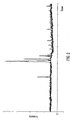
- Fig. 1 shows a portion of a single time of flight spectrum which was obtained by mass analysing the [M+6H] 6+ isotope cluster from a sample of Bovine insulin.
- the ions shown in Fig. 1 were measured as having a flight time of approximately 42 ⁇ s.
- the sample was ionised by Electrospray ionisation and positive ions were analysed using an orthogonal acceleration Time of Flight mass spectrometer or mass analyser.
- the ions were detected using a micro-channel plate ion detector. Secondary electrons generated by the high energy analyte ions were subsequently amplified and the subsequent electron current was capacitively coupled to ground potential.
- the electric current was then amplified using a current to voltage converter and was digitised at a frequency of 5 GHz using an 8 bit vertical resolution Analogue to Digital Converter.
- the strongest or most intense ions signals resulted from the simultaneous arrival of multiple ion having the same mass to charge ratio from within the isotope cluster.
- the weakest signals resulted from ions arriving individually at the ion detector.
- Fig. 1 It is apparent from Fig. 1 that a shift in the level of the baseline is observed after the largest ion arrival event.
- the shift in the baseline level is due, in part, to AC coupling effects in the ion detector and in the amplification electronics.
- the DC baseline is also offset above zero level.
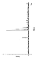
- Fig. 2 shows the time of flight data as shown in Fig. 1 together with a superimposed representation of the estimated baseline value across the time of flight spectrum.
- Fig. 3 shows the data as shown in Fig. 1 after it has been processed in a conventional manner. After all the data was obtained a baseline value was then calculated from the data. A threshold was applied which was set at a fixed value relative to the calculated baseline. The threshold value was set to be higher than the electronic noise. Data points which were below the threshold value were assigned a value equal to the calculated baseline value. Data points which exceeded the threshold value were left unchanged i.e. they were assigned a value equal to the signal recorded by the Analogue to Digital Converter.
- Fig. 4 shows a corresponding signal as obtained according to an embodiment of the present invention.
- a baseline value was calculated dynamically and was dynamically subtracted from each data point as data was still in the process of being acquired (i.e. not as a post-processing step).
- changes in the baseline value due to the arrival of relatively intense ion signals are corrected for as data is actually being acquired.
- the DC offset associated with the data is dynamically corrected for.
- the data may then be summed or averaged with subsequent spectra which have been acquired and processed in a similar way. Alternatively, the data may first be subject to further processing prior to summing or averaging spectra.
- Fig. 5 shows the data shown in Fig. 4 after being processed according to a preferred embodiment of the present invention wherein a fixed threshold was applied to the data. Data points which fell below the threshold were set to zero whereas data points which exceeded the threshold were allowed to retain their value i.e. they were assigned a value equal to the signal recorded by the Analogue to Digital Converter after subtraction of the calculated baseline. The application of a threshold decreases the noise in the resulting time of flight spectrum and the variation in the baseline.
- the baseline calculation step, the baseline subtraction step and the noise thresholding step may advantageously be performed for each data point as it is being acquired in a substantially simultaneous manner using parallel processors.
- the method according to the preferred embodiment may be considered as comprising repetitively determining a value corresponding to the baseline of the output signal and assigning a threshold value for each data point by adding a pre-defined threshold level to the calculated baseline value for that data point.
- a value of zero is preferably assigned if the output signal falls below the threshold value.
- a value corresponding to the output signal minus the calculated baseline value is preferably assigned if the output signal exceeds the threshold value.
- a fast determination of the median (i.e. 50% percentile) or of another percentile of the data as each data point is determined is preferably made.
- the median value or other preferred percentile is preferably used as the determined baseline value. This approach preferably has the advantage of being fast and is preferably able to adapt dynamically to any changes in the baseline level.
- the first register preferably comprises a baseline value register (BV) and the second register preferably comprises a baseline fraction register (BF).
- the value in the baseline value register BV is preferably set to a value which preferably comprises an initial estimate of the baseline.
- the estimate of the baseline may be determined by recording a background spectrum (i.e. without any analyte being present) or by setting the value to an arbitrary or predicted value.
- the value in the baseline fraction register BF which has a length n is preferably set to n/2.
- the value in the baseline fraction register BF is preferably incremented by an integer value A so that the value in the baseline fraction register BF preferably equals n/2 + A.
- the value in the baseline fraction register BF is preferably decremented by an integer value B so that the value in the baseline fraction register BF preferably equals n/2 -B.
- the value in the baseline fraction register BF is within the range from zero to n (i.e. 0 ⁇ BF ⁇ n) then the value in the baseline value register BV is preferably subtracted from the data point and the value is preferably stored.
- the value in the baseline fraction register BF is preferably increased by an amount C before being subtracted from the data point and the value is preferably stored.
- the value in the baseline fraction register BF is then preferably reset to a value equal to n/2 prior to interrogation of the next data point.
- the value in the baseline fraction register BF is preferably decreased by an amount D before being subtracted from the data point and the value is preferably stored.
- the value in the baseline fraction register BF is then preferably reset to a value equal to n/2 prior to interrogation of the next data point.
- the process is preferably repeated in turn for each data point in the time of flight spectrum as the time of flight spectrum is being acquired.
- n was set at 50
- A was set at 8
- B was set at 1
- C and D were set to be equivalent to one bit of the eight bit digitiser.
- the mass spectrometer may, for example, comprise a quadrupole mass filter, an ion trap or a magnetic sector mass spectrometer.
- the value corresponding to the baseline level may be determined using analogue, digital electronics or a combination of both analogue and digital electronics.
- the baseline level may be subtracted using analogue electronics, digital electronics or a combination of both analogue and digital electronics.
- the signal may be recorded using a Time to Digital Converter (TDC) immediately after background subtraction has been performed.
- TDC Time to Digital Converter
- the output signal is not digitised using an Analogue to Digital Converter.
- the output signal is preferably compared to a reference value which is preferably derived, for example, from a Digital to Analogue Converter (DAC).
- DAC Digital to Analogue Converter
- the output from the comparator which is preferably used to make the comparison may be used to increment or decrement a counter which in turn may then be used to drive the Digital to Analogue Converter providing the reference value.
- the reference value preferably comprises the determined baseline value and is preferably subtracted from the output signal.
Landscapes
- Chemical & Material Sciences (AREA)
- Analytical Chemistry (AREA)
- Other Investigation Or Analysis Of Materials By Electrical Means (AREA)
- Electron Tubes For Measurement (AREA)
Abstract
Claims (13)
- Procédé de détection d'ions, comprenant :la numérisation d'un premier signal délivré en sortie par un détecteur d'ions afin de produire une pluralité de premières valeurs de signal correspondantes ;la détermination dynamique du niveau de fond ou de base dudit premier signal ou desdites premières valeurs de signal ; etla soustraction dynamique dudit niveau de fond ou de base dudit premier signal ou desdites premières valeurs de signal audit premier signal ou auxdites premières valeurs de signal afin de produire une pluralité de secondes valeurs de signal ;caractérisé en ce que :le niveau de fond ou de base dudit premier signal ou desdites premières valeurs de signal est déterminé par détermination d'une médiane ou d'un autre centile dudit premier signal ou desdites premières valeurs de signal pendant une période de temps antérieure t1.
- Procédé selon la revendication 1, dans lequel ladite étape de numérisation dudit premier signal comprend l'utilisation d'un convertisseur analogique à numérique (CAN) pour numériser ledit premier signal, ledit convertisseur analogique à numérique :(a) étant mis en fonctionnement, lors de l'utilisation, à une fréquence de numérisation sélectionnée dans le groupe comprenant : (i) < 1 GHz ; (ii) 1-2 GHz ; (iii) 2-3 GHz ; (iv) 3-4 GHz ; (v) 4-5 GHz ; (vi) 5-6 GHz ; (vii) 6-7 GHz ; (viii) 7-8 GHz ; (ix) 8-9 GHz ; (x) 9-10 GHz ; et (xi) > 10 GHz ; et/ou (b) comprend une résolution sélectionnée dans le groupe comprenant : (i) au moins 4 bits ; (ii) au moins 5 bits ; (iii) au moins 6 bits ; (iv) au moins 7 bits ; (v) au moins 8 bits ; (vi) au moins 9 bits ; (vii) au moins 10 bits ; (viii) au moins 11 bits ; (ix) au moins 12 bits ; (x) au moins 13 bits ; (xi) au moins 14 bits ; (xii) au moins 15 bits ; et (xiii) au moins 16 bits.
- Procédé selon la revendication 1 ou 2, dans lequel ladite étape de détermination dynamique dudit niveau de fond ou de base dudit premier signal ou desdites premières valeurs de signal comprend :(a) la détermination dynamique dudit niveau de fond ou de base pendant l'acquisition de données de temps de vol et/ou de données spectrales de masse ; et/ou(b) la détermination dynamique dudit niveau de fond ou de base pour un premier signal qui est produit du fait d'un groupe d'ions pendant une période de temps après que ledit groupe d'ions a été accéléré dans une région de temps de vol ou de dérive d'un analyseur de masse à temps de vol et avant tous les ions dudit groupe n'atteignent un détecteur d'ions ; et/ou(c) la détermination dynamique dudit niveau de fond ou de base en temps réel pendant qu'un ensemble de données de temps de vol et/ou de données spectrales de masse concernant un groupe d'ions est encore en cours d'acquisition et non pas sous la forme d'une étape de post-traitement après qu'un ensemble de données de temps de vol et/ou de données spectrales de masse concernant le groupe d'ions a été entièrement acquis.
- Procédé selon l'une quelconque des revendications 1, 2 ou 3, dans lequel ladite étape de détermination d'une médiane ou d'un autre centile dudit premier signal ou desdites premières valeurs de signal comprend la détermination d'un centile dudit premier signal ou desdites premières valeurs de signal pendant ladite période de temps antérieure t1 dans une gamme sélectionnée dans le groupe comprenant : (i) < 10 % ; (ii) < 10-20 % ; (iii) 20-30 % ; (iv) 30-40 % ; (v) 40-50 % ; (vi) 50-60 % ; (vii) 60-70 % ; (viii) 70-80 % ; (ix) 80-90 % ; (x) > 90 %.
- Procédé selon l'une quelconque des revendications précédentes, dans lequel ladite étape de détermination d'une médiane ou d'un autre centile dudit premier signal ou desdites premières valeurs de signal pendant une période de temps antérieure t1 comprend en outre le fait de déterminer si ledit premier signal ou ladite première valeur de signal est supérieur ou inférieur à la médiane ou au centile courant déterminé dudit premier signal ou desdites premières valeurs de signal, dans lequel :(a) si ledit premier signal ou ladite première valeur de signal est supérieure à ladite médiane ou audit centile courant déterminé dudit premier signal ou desdites premières valeurs de signal, une première valeur constante est alors ajoutée à ladite médiane ou audit centile courant déterminé ; et(b) si ledit premier signal ou ladite première valeur de signal est inférieure à ladite médiane ou audit centile courant déterminé dudit premier signal ou desdites premières valeurs de signal, une seconde valeur constante est alors soustraite à ladite médiane ou audit centile courant déterminé ;dans lequel ladite première valeur constante est sensiblement identique à, ou sensiblement différente de ladite seconde valeur constante.
- Procédé selon l'une quelconque des revendications précédentes, dans lequel ladite étape de détermination dynamique dudit niveau de fond ou de base dudit premier signal ou desdites premières valeurs de signal comprend l'utilisation d'un premier registre de valeur de base et/ou d'un second registre de fraction de base, dans lequel :(a) si ledit premier signal ou ladite première valeur de signal est supérieure à la valeur stockée dans ledit premier registre de valeur de base, une valeur entière est alors ajoutée à la valeur stockée dans ledit second registre de fraction de base ; et(b) si ledit premier signal ou ladite première valeur de signal est inférieure à la valeur stockée dans ledit premier registre de valeur de base, une valeur entière est alors soustraite à la valeur stockée dans ledit second registre de fraction de base.
- Procédé selon l'une quelconque des revendications précédentes, dans lequel :(a) pendant l'acquisition d'un ensemble unique de données de temps de vol ou de données spectrales de masse correspondant à un groupe unique d'ions qui sont accélérés dans une région de temps de vol ou de dérive d'un analyseur de masse à temps de vol, au moins x premières valeurs de signal ou valeurs de données sont obtenues au cours d'une période de temps T, x étant sélectionné dans le groupe comprenant : (i) 1000 ; (ii) 1000-5000 ; (iii) 5000-10000 ; (iv) 10000-50000 ; (v) 50000-100000 ; (vi) 100000-500000 ; (vii) 500000-1000000 ; et (viii) > 1000000, et le rapport de ladite période de temps antérieure t1 à ladite période de temps T étant sélectionné dans le groupe comprenant : (i) ≤ 50 % ; (ii) ≤ 10 % ; (iii) ≤ 5 %; (iv) ≤ 1 ; (v) ≤ 0,5 % ; (vi) ≤ 0,1 %; (vii) ≤ 0,05 % ; (viii) ≤ 0,01 % ; (ix) ≤ 0,005 % ; (x) ≤ 0,001 % ; (xi) ≤ 0,0005 % ; (xii) ≤ 0,0001 % ; (xiii) ≤ 0,00005 % ; et (xiv) ≤ 0,00001 % ; et/ou(b) ladite période de temps antérieure t1 correspond à un temps pendant lequel y premières valeurs de signal ou valeurs de données sont obtenus, y étant sélectionné dans le groupe comprenant : (i) < 10 ; (ii) 10-50 ; (iii) 50-100 ; (iv) 100-500 ; (v) 500-1000 ; (vi) 1000-5000 ; (vii) 5000-10000 ; (viii) 10000-50000 ; et (ix) > 50000.
- Procédé selon l'une quelconque des revendications précédentes, dans lequel :(a) un ensemble unique de données de temps de vol ou de données spectrales de masse correspondant à un groupe unique d'ions qui sont accélérés dans une région de temps de vol ou de dérive d'un analyseur de masse à temps de vol est acquis pendant une période de temps T sélectionnée dans le groupe comprenant : (i) < 500 ns ; (ii) 500-1000 ns ; (iii) 1-5 µs ; (iv) 5-10 µs ; (v) 10-50 µs ; (vi) 50-100 µs ; (vii) 1.00-500 µs ; (viii) 500-1000 µs ; et (ix) > 1 ms, et le rapport de ladite période de temps antérieure t1 à ladite période de temps T étant sélectionné dans le groupe comprenant : (i) ≤ 50 % ; (ii) ≤ 10 % ; (iii) ≤ 5 % ; (iv) ≤ 1 ; (v) ≤ 0,5 % ; (vi) ≤ 0,1 %; (vii) ≤ 0,05 % ; (viii) ≤ 0,01 % ; (ix) ≤ 0,005 %; (x) ≤ 0,001 % ; (xi) ≤ 0,0005 % (xii) ≤ 0,0001 % ; (xiii) ≤ 0,00005 % ; et (xiv) ≤ 0,00001 % ; et/ou(b) ladite période de temps antérieure t1 est sélectionnée dans le groupe comprenant : (i) < 5 ns ; (ii) 5-10 ns ; (iii) 10-50 ns ; (iv) 50-100 ns ; (v) 100-500 ns ; (vi) 500-1000 ns; (vii) 1-5 µs (viii) 5-10 µs ; (ix) 10-50 µs ; (x) 50-100 µs ; (xi) 100-500 µs (xii) 500-1000 µs ; et (xiii) > 1 ms.
- Procédé selon l'une quelconque des revendications précédentes, comprenant en outre la comparaison desdites secondes valeurs de signal à une valeur de seuil, dans lequel :(a) si l'une desdites secondes valeurs de signal s'abaisse en dessous de ladite valeur de seuil, on affecte alors à ladite seconde valeur de signal une valeur égale à 0, ou sinon on la réduit sensiblement ; et/ou(b) si l'une desdites secondes valeurs de signal s'abaisse au-dessus de ladite valeur de seuil, ladite seconde valeur de signal est alors laissée sensiblement inchangée.
- Procédé selon la revendication 9, dans lequel ladite étape de comparaison desdites secondes valeurs de signal à une valeur de seuil comprend :(a) la comparaison dynamique desdites secondes valeurs de signal à ladite valeur de seuil pendant l'acquisition de données de temps de vol et/ou de données spectrales de masse ; et(b) la comparaison dynamique desdites secondes valeurs de signal à ladite valeur de seuil, lesdites secondes valeurs de signal correspondant à un premier signal qui est produit du fait d'un groupe d'ions pendant une période de temps après que ledit groupe d'ions a été accéléré dans une région de temps de vol ou de dérive d'un analyseur de masse à temps de vol et avant que tous les ions dudit groupe n'atteignent un détecteur d'ions ; et/ou(c) la comparaison dynamique desdites secondes valeurs de signal à ladite valeur de seuil en temps réel pendant qu'un ensemble de données de temps de vol et/ou de données spectrales de masse concernant un groupe d'ions est encore en cours d'acquisition et non pas sous la forme d'une étape de post-traitement après qu'un ensemble de données de temps de vol et/ou de données spectrales de masse concernant le groupe d'ions a été entièrement acquis.
- Procédé de spectrométrie de masse comprenant un procédé selon l'une quelconque des revendications précédentes.
- Système détecteur d'ions comprenant :un dispositif conçu pour, et apte à numériser un premier signal qui est fourni en sortie par un détecteur d'ions afin de produire une pluralité de premières valeurs de signal correspondantes ;un dispositif conçu pour, et apte à déterminer dynamiquement le niveau de fond ou de base dudit premier signal ou desdites premières valeurs de signal ; etun dispositif conçu pour, et apte à soustraire dynamiquement ledit niveau de fond ou de base dudit premier signal ou desdites premières valeurs de signal audit premier signal ou auxdites premières valeurs de signal afin de produire une pluralité de secondes valeurs de signal ;caractérisé en ce queledit dispositif de détermination dynamique de niveau de fond ou de base dudit premier signal ou desdites premières valeurs de signal est conçu pour déterminer le niveau de fond ou de base en déterminant une médiane ou un autre centile dudit premier signal ou desdites premières valeurs de signal pendant un période de temps antérieure t1.
- Spectromètre de masse comprenant en outre un système détecteur d'ions selon la revendication 12.
Applications Claiming Priority (3)
| Application Number | Priority Date | Filing Date | Title |
|---|---|---|---|
| GBGB0709312.3A GB0709312D0 (en) | 2007-05-15 | 2007-05-15 | Mass spectrometer |
| US94049407P | 2007-05-29 | 2007-05-29 | |
| PCT/GB2008/001663 WO2008139193A2 (fr) | 2007-05-15 | 2008-05-14 | Spectromètre de masse |
Publications (2)
| Publication Number | Publication Date |
|---|---|
| EP2147453A2 EP2147453A2 (fr) | 2010-01-27 |
| EP2147453B1 true EP2147453B1 (fr) | 2012-07-11 |
Family
ID=38219430
Family Applications (1)
| Application Number | Title | Priority Date | Filing Date |
|---|---|---|---|
| EP08750596A Active EP2147453B1 (fr) | 2007-05-15 | 2008-05-14 | Spectromètre de masse |
Country Status (6)
| Country | Link |
|---|---|
| US (1) | US8598513B2 (fr) |
| EP (1) | EP2147453B1 (fr) |
| JP (1) | JP4921588B2 (fr) |
| CA (1) | CA2687181C (fr) |
| GB (2) | GB0709312D0 (fr) |
| WO (1) | WO2008139193A2 (fr) |
Families Citing this family (20)
| Publication number | Priority date | Publication date | Assignee | Title |
|---|---|---|---|---|
| DE102008023694B4 (de) * | 2008-05-15 | 2010-12-30 | Bruker Daltonik Gmbh | Fragmentierung von Analytionen durch Ionenstoß in HF-Ionenfallen |
| GB0909289D0 (en) * | 2009-05-29 | 2009-07-15 | Micromass Ltd | Method of processing mass spectral data |
| GB201002447D0 (en) | 2010-02-12 | 2010-03-31 | Micromass Ltd | Mass spectrometer |
| CA2825280A1 (fr) * | 2011-01-21 | 2012-07-26 | Massdefect Technologies, Llc | Acquisition dependante des donnees, facilitee par une soustraction d'arriere-plan |
| US8942943B2 (en) * | 2011-07-15 | 2015-01-27 | Bruker Daltonics, Inc. | Dynamic range improvement for mass spectrometry |
| US20130015344A1 (en) * | 2011-07-15 | 2013-01-17 | Bruker Daltonics, Inc. | Background noise correction in quadrupole mass spectrometers |
| GB201208841D0 (en) * | 2012-05-18 | 2012-07-04 | Micromass Ltd | Calibrating dual adc acquisition system |
| AU2013267976B2 (en) | 2012-05-29 | 2016-06-02 | Biodesix, Inc. | Deep-MALDI TOF mass spectrometry of complex biological samples, e.g., serum, and uses thereof |
| US9196467B2 (en) | 2013-03-11 | 2015-11-24 | 1St Detect Corporation | Mass spectrum noise cancellation by alternating inverted synchronous RF |
| DE112014003221B4 (de) | 2013-07-09 | 2024-05-23 | Micromass Uk Limited | Verfahren zum Aufzeichnen einer ADC-Sättigung |
| WO2015118321A1 (fr) | 2014-02-04 | 2015-08-13 | Micromass Uk Limited | Procédé optimisé de surveillance de réactions multiples ou d'enregistrement d'ion unique |
| US9928999B2 (en) | 2014-06-11 | 2018-03-27 | Micromass Uk Limited | Flagging ADC coalescence |
| WO2015198228A1 (fr) * | 2014-06-23 | 2015-12-30 | Dh Technologies Development Pte. Ltd | Compensation de diaphonie pour alimentation électrique de spectrométrie de mobilité ionique |
| GB2541385B (en) * | 2015-08-14 | 2020-01-01 | Thermo Fisher Scient Bremen Gmbh | Dynamic range improvement for isotope ratio mass spectrometry |
| US10026598B2 (en) * | 2016-01-04 | 2018-07-17 | Rohde & Schwarz Gmbh & Co. Kg | Signal amplitude measurement and calibration with an ion trap |
| JP6683015B2 (ja) * | 2016-05-26 | 2020-04-15 | 株式会社島津製作所 | 分析データ処理装置 |
| CN110234991B (zh) * | 2017-01-30 | 2021-07-09 | 株式会社岛津制作所 | 谱数据处理装置 |
| CN113311496B (zh) * | 2021-06-11 | 2022-07-19 | 中国科学院精密测量科学与技术创新研究院 | 一种基于双组分原子交织干涉效应的重力仪 |
| WO2023211786A1 (fr) * | 2022-04-27 | 2023-11-02 | Elemental Scientific, Inc. | Commutation de processus de données multiples pour la détermination de seuil de ligne de base et de détection de nanoparticules |
| US12085497B1 (en) | 2023-04-12 | 2024-09-10 | Elemental Scientific, Inc. | Nanoparticle analysis for ultra-low level concentrations of nanoparticles in fluid samples |
Family Cites Families (6)
| Publication number | Priority date | Publication date | Assignee | Title |
|---|---|---|---|---|
| DE10152821B4 (de) | 2001-10-25 | 2006-11-16 | Bruker Daltonik Gmbh | Massenspektren ohne elektronisches Rauschen |
| KR100492898B1 (ko) * | 2001-12-14 | 2005-06-03 | 주식회사 하이닉스반도체 | 반도체 소자 제조 방법 |
| US6680476B1 (en) | 2002-11-22 | 2004-01-20 | Agilent Technologies, Inc. | Summed time-of-flight mass spectrometry utilizing thresholding to reduce noise |
| GB0329554D0 (en) | 2003-12-22 | 2004-01-28 | Micromass Ltd | Mass spectrometer |
| JP4575193B2 (ja) | 2005-02-25 | 2010-11-04 | 株式会社日立ハイテクノロジーズ | 質量分析装置および質量分析方法 |
| US8648294B2 (en) * | 2006-10-17 | 2014-02-11 | The Regents Of The University Of California | Compact aerosol time-of-flight mass spectrometer |
-
2007
- 2007-05-15 GB GBGB0709312.3A patent/GB0709312D0/en not_active Ceased
-
2008
- 2008-05-14 EP EP08750596A patent/EP2147453B1/fr active Active
- 2008-05-14 CA CA2687181A patent/CA2687181C/fr not_active Expired - Fee Related
- 2008-05-14 GB GB0808828A patent/GB2450959B/en active Active
- 2008-05-14 WO PCT/GB2008/001663 patent/WO2008139193A2/fr active Application Filing
- 2008-05-14 US US12/600,209 patent/US8598513B2/en active Active
- 2008-05-14 JP JP2010507972A patent/JP4921588B2/ja active Active
Also Published As
| Publication number | Publication date |
|---|---|
| WO2008139193A2 (fr) | 2008-11-20 |
| CA2687181A1 (fr) | 2008-11-20 |
| US8598513B2 (en) | 2013-12-03 |
| US20110049353A1 (en) | 2011-03-03 |
| JP2010527019A (ja) | 2010-08-05 |
| JP4921588B2 (ja) | 2012-04-25 |
| GB2450959A (en) | 2009-01-14 |
| GB2450959B (en) | 2009-09-23 |
| EP2147453A2 (fr) | 2010-01-27 |
| CA2687181C (fr) | 2016-04-26 |
| GB0808828D0 (en) | 2008-06-18 |
| WO2008139193A3 (fr) | 2009-08-13 |
| GB0709312D0 (en) | 2007-06-20 |
Similar Documents
| Publication | Publication Date | Title |
|---|---|---|
| EP2147453B1 (fr) | Spectromètre de masse | |
| US9053911B2 (en) | Method of processing mass spectral data | |
| US8063358B2 (en) | Mass spectrometer | |
| US8941056B2 (en) | Mass spectrometer | |
| EP2022074B1 (fr) | Spectromètre de masse | |
| EP2022075B1 (fr) | Spectromètre de masse | |
| US10211037B2 (en) | Histogramming different ion areas on peak detecting analogue to digital convertors |
Legal Events
| Date | Code | Title | Description |
|---|---|---|---|
| PUAI | Public reference made under article 153(3) epc to a published international application that has entered the european phase |
Free format text: ORIGINAL CODE: 0009012 |
|
| 17P | Request for examination filed |
Effective date: 20091110 |
|
| AK | Designated contracting states |
Kind code of ref document: A2 Designated state(s): AT BE BG CH CY CZ DE DK EE ES FI FR GB GR HR HU IE IS IT LI LT LU LV MC MT NL NO PL PT RO SE SI SK TR |
|
| AX | Request for extension of the european patent |
Extension state: AL BA MK RS |
|
| 17Q | First examination report despatched |
Effective date: 20100910 |
|
| GRAP | Despatch of communication of intention to grant a patent |
Free format text: ORIGINAL CODE: EPIDOSNIGR1 |
|
| RIC1 | Information provided on ipc code assigned before grant |
Ipc: H01J 49/00 20060101AFI20111123BHEP Ipc: G06K 9/00 20060101ALI20111123BHEP |
|
| DAX | Request for extension of the european patent (deleted) | ||
| RBV | Designated contracting states (corrected) |
Designated state(s): AT BE BG CH CY CZ DE DK EE ES FI FR GR HR HU IE IS IT LI LT LU LV MC MT NL NO PL PT RO SE SI SK TR |
|
| GRAS | Grant fee paid |
Free format text: ORIGINAL CODE: EPIDOSNIGR3 |
|
| GRAA | (expected) grant |
Free format text: ORIGINAL CODE: 0009210 |
|
| AK | Designated contracting states |
Kind code of ref document: B1 Designated state(s): AT BE BG CH CY CZ DE DK EE ES FI FR GR HR HU IE IS IT LI LT LU LV MC MT NL NO PL PT RO SE SI SK TR |
|
| REG | Reference to a national code |
Ref country code: CH Ref legal event code: EP |
|
| REG | Reference to a national code |
Ref country code: AT Ref legal event code: REF Ref document number: 566497 Country of ref document: AT Kind code of ref document: T Effective date: 20120715 |
|
| REG | Reference to a national code |
Ref country code: IE Ref legal event code: FG4D |
|
| REG | Reference to a national code |
Ref country code: DE Ref legal event code: R096 Ref document number: 602008017124 Country of ref document: DE Effective date: 20120906 |
|
| REG | Reference to a national code |
Ref country code: NL Ref legal event code: VDEP Effective date: 20120711 |
|
| REG | Reference to a national code |
Ref country code: AT Ref legal event code: MK05 Ref document number: 566497 Country of ref document: AT Kind code of ref document: T Effective date: 20120711 |
|
| REG | Reference to a national code |
Ref country code: LT Ref legal event code: MG4D Effective date: 20120711 |
|
| PG25 | Lapsed in a contracting state [announced via postgrant information from national office to epo] |
Ref country code: HR Free format text: LAPSE BECAUSE OF FAILURE TO SUBMIT A TRANSLATION OF THE DESCRIPTION OR TO PAY THE FEE WITHIN THE PRESCRIBED TIME-LIMIT Effective date: 20120711 Ref country code: CY Free format text: LAPSE BECAUSE OF FAILURE TO SUBMIT A TRANSLATION OF THE DESCRIPTION OR TO PAY THE FEE WITHIN THE PRESCRIBED TIME-LIMIT Effective date: 20120711 Ref country code: BE Free format text: LAPSE BECAUSE OF FAILURE TO SUBMIT A TRANSLATION OF THE DESCRIPTION OR TO PAY THE FEE WITHIN THE PRESCRIBED TIME-LIMIT Effective date: 20120711 Ref country code: LT Free format text: LAPSE BECAUSE OF FAILURE TO SUBMIT A TRANSLATION OF THE DESCRIPTION OR TO PAY THE FEE WITHIN THE PRESCRIBED TIME-LIMIT Effective date: 20120711 Ref country code: IS Free format text: LAPSE BECAUSE OF FAILURE TO SUBMIT A TRANSLATION OF THE DESCRIPTION OR TO PAY THE FEE WITHIN THE PRESCRIBED TIME-LIMIT Effective date: 20121111 Ref country code: AT Free format text: LAPSE BECAUSE OF FAILURE TO SUBMIT A TRANSLATION OF THE DESCRIPTION OR TO PAY THE FEE WITHIN THE PRESCRIBED TIME-LIMIT Effective date: 20120711 Ref country code: FI Free format text: LAPSE BECAUSE OF FAILURE TO SUBMIT A TRANSLATION OF THE DESCRIPTION OR TO PAY THE FEE WITHIN THE PRESCRIBED TIME-LIMIT Effective date: 20120711 Ref country code: NO Free format text: LAPSE BECAUSE OF FAILURE TO SUBMIT A TRANSLATION OF THE DESCRIPTION OR TO PAY THE FEE WITHIN THE PRESCRIBED TIME-LIMIT Effective date: 20121011 |
|
| PG25 | Lapsed in a contracting state [announced via postgrant information from national office to epo] |
Ref country code: PL Free format text: LAPSE BECAUSE OF FAILURE TO SUBMIT A TRANSLATION OF THE DESCRIPTION OR TO PAY THE FEE WITHIN THE PRESCRIBED TIME-LIMIT Effective date: 20120711 Ref country code: LV Free format text: LAPSE BECAUSE OF FAILURE TO SUBMIT A TRANSLATION OF THE DESCRIPTION OR TO PAY THE FEE WITHIN THE PRESCRIBED TIME-LIMIT Effective date: 20120711 Ref country code: SI Free format text: LAPSE BECAUSE OF FAILURE TO SUBMIT A TRANSLATION OF THE DESCRIPTION OR TO PAY THE FEE WITHIN THE PRESCRIBED TIME-LIMIT Effective date: 20120711 Ref country code: GR Free format text: LAPSE BECAUSE OF FAILURE TO SUBMIT A TRANSLATION OF THE DESCRIPTION OR TO PAY THE FEE WITHIN THE PRESCRIBED TIME-LIMIT Effective date: 20121012 Ref country code: PT Free format text: LAPSE BECAUSE OF FAILURE TO SUBMIT A TRANSLATION OF THE DESCRIPTION OR TO PAY THE FEE WITHIN THE PRESCRIBED TIME-LIMIT Effective date: 20121112 Ref country code: SE Free format text: LAPSE BECAUSE OF FAILURE TO SUBMIT A TRANSLATION OF THE DESCRIPTION OR TO PAY THE FEE WITHIN THE PRESCRIBED TIME-LIMIT Effective date: 20120711 |
|
| PG25 | Lapsed in a contracting state [announced via postgrant information from national office to epo] |
Ref country code: NL Free format text: LAPSE BECAUSE OF FAILURE TO SUBMIT A TRANSLATION OF THE DESCRIPTION OR TO PAY THE FEE WITHIN THE PRESCRIBED TIME-LIMIT Effective date: 20120711 |
|
| PG25 | Lapsed in a contracting state [announced via postgrant information from national office to epo] |
Ref country code: ES Free format text: LAPSE BECAUSE OF FAILURE TO SUBMIT A TRANSLATION OF THE DESCRIPTION OR TO PAY THE FEE WITHIN THE PRESCRIBED TIME-LIMIT Effective date: 20121022 Ref country code: DK Free format text: LAPSE BECAUSE OF FAILURE TO SUBMIT A TRANSLATION OF THE DESCRIPTION OR TO PAY THE FEE WITHIN THE PRESCRIBED TIME-LIMIT Effective date: 20120711 Ref country code: RO Free format text: LAPSE BECAUSE OF FAILURE TO SUBMIT A TRANSLATION OF THE DESCRIPTION OR TO PAY THE FEE WITHIN THE PRESCRIBED TIME-LIMIT Effective date: 20120711 Ref country code: EE Free format text: LAPSE BECAUSE OF FAILURE TO SUBMIT A TRANSLATION OF THE DESCRIPTION OR TO PAY THE FEE WITHIN THE PRESCRIBED TIME-LIMIT Effective date: 20120711 Ref country code: CZ Free format text: LAPSE BECAUSE OF FAILURE TO SUBMIT A TRANSLATION OF THE DESCRIPTION OR TO PAY THE FEE WITHIN THE PRESCRIBED TIME-LIMIT Effective date: 20120711 |
|
| PLBE | No opposition filed within time limit |
Free format text: ORIGINAL CODE: 0009261 |
|
| STAA | Information on the status of an ep patent application or granted ep patent |
Free format text: STATUS: NO OPPOSITION FILED WITHIN TIME LIMIT |
|
| PG25 | Lapsed in a contracting state [announced via postgrant information from national office to epo] |
Ref country code: SK Free format text: LAPSE BECAUSE OF FAILURE TO SUBMIT A TRANSLATION OF THE DESCRIPTION OR TO PAY THE FEE WITHIN THE PRESCRIBED TIME-LIMIT Effective date: 20120711 Ref country code: IT Free format text: LAPSE BECAUSE OF FAILURE TO SUBMIT A TRANSLATION OF THE DESCRIPTION OR TO PAY THE FEE WITHIN THE PRESCRIBED TIME-LIMIT Effective date: 20120711 |
|
| 26N | No opposition filed |
Effective date: 20130412 |
|
| PG25 | Lapsed in a contracting state [announced via postgrant information from national office to epo] |
Ref country code: BG Free format text: LAPSE BECAUSE OF FAILURE TO SUBMIT A TRANSLATION OF THE DESCRIPTION OR TO PAY THE FEE WITHIN THE PRESCRIBED TIME-LIMIT Effective date: 20121011 |
|
| REG | Reference to a national code |
Ref country code: DE Ref legal event code: R097 Ref document number: 602008017124 Country of ref document: DE Effective date: 20130412 |
|
| PG25 | Lapsed in a contracting state [announced via postgrant information from national office to epo] |
Ref country code: MC Free format text: LAPSE BECAUSE OF FAILURE TO SUBMIT A TRANSLATION OF THE DESCRIPTION OR TO PAY THE FEE WITHIN THE PRESCRIBED TIME-LIMIT Effective date: 20120711 |
|
| REG | Reference to a national code |
Ref country code: CH Ref legal event code: PL |
|
| PG25 | Lapsed in a contracting state [announced via postgrant information from national office to epo] |
Ref country code: CH Free format text: LAPSE BECAUSE OF NON-PAYMENT OF DUE FEES Effective date: 20130531 Ref country code: LI Free format text: LAPSE BECAUSE OF NON-PAYMENT OF DUE FEES Effective date: 20130531 |
|
| REG | Reference to a national code |
Ref country code: IE Ref legal event code: MM4A |
|
| PG25 | Lapsed in a contracting state [announced via postgrant information from national office to epo] |
Ref country code: IE Free format text: LAPSE BECAUSE OF NON-PAYMENT OF DUE FEES Effective date: 20130514 |
|
| PG25 | Lapsed in a contracting state [announced via postgrant information from national office to epo] |
Ref country code: MT Free format text: LAPSE BECAUSE OF FAILURE TO SUBMIT A TRANSLATION OF THE DESCRIPTION OR TO PAY THE FEE WITHIN THE PRESCRIBED TIME-LIMIT Effective date: 20120711 |
|
| PG25 | Lapsed in a contracting state [announced via postgrant information from national office to epo] |
Ref country code: TR Free format text: LAPSE BECAUSE OF FAILURE TO SUBMIT A TRANSLATION OF THE DESCRIPTION OR TO PAY THE FEE WITHIN THE PRESCRIBED TIME-LIMIT Effective date: 20120711 |
|
| PG25 | Lapsed in a contracting state [announced via postgrant information from national office to epo] |
Ref country code: HU Free format text: LAPSE BECAUSE OF FAILURE TO SUBMIT A TRANSLATION OF THE DESCRIPTION OR TO PAY THE FEE WITHIN THE PRESCRIBED TIME-LIMIT; INVALID AB INITIO Effective date: 20080514 Ref country code: LU Free format text: LAPSE BECAUSE OF NON-PAYMENT OF DUE FEES Effective date: 20130514 |
|
| REG | Reference to a national code |
Ref country code: FR Ref legal event code: PLFP Year of fee payment: 9 |
|
| REG | Reference to a national code |
Ref country code: FR Ref legal event code: PLFP Year of fee payment: 10 |
|
| REG | Reference to a national code |
Ref country code: FR Ref legal event code: PLFP Year of fee payment: 11 |
|
| PGFP | Annual fee paid to national office [announced via postgrant information from national office to epo] |
Ref country code: FR Payment date: 20180423 Year of fee payment: 11 |
|
| PG25 | Lapsed in a contracting state [announced via postgrant information from national office to epo] |
Ref country code: FR Free format text: LAPSE BECAUSE OF NON-PAYMENT OF DUE FEES Effective date: 20190531 |
|
| REG | Reference to a national code |
Ref country code: DE Ref legal event code: R082 Ref document number: 602008017124 Country of ref document: DE |
|
| P01 | Opt-out of the competence of the unified patent court (upc) registered |
Effective date: 20230506 |
|
| PGFP | Annual fee paid to national office [announced via postgrant information from national office to epo] |
Ref country code: DE Payment date: 20240418 Year of fee payment: 17 |