EP2147272B1 - Zentrifugales pellettrocknungssieb mit integrierten eingeprägten deflektorstreifen - Google Patents
Zentrifugales pellettrocknungssieb mit integrierten eingeprägten deflektorstreifen Download PDFInfo
- Publication number
- EP2147272B1 EP2147272B1 EP08754632.1A EP08754632A EP2147272B1 EP 2147272 B1 EP2147272 B1 EP 2147272B1 EP 08754632 A EP08754632 A EP 08754632A EP 2147272 B1 EP2147272 B1 EP 2147272B1
- Authority
- EP
- European Patent Office
- Prior art keywords
- screen
- deflector
- set forth
- dryer
- embossed
- Prior art date
- Legal status (The legal status is an assumption and is not a legal conclusion. Google has not performed a legal analysis and makes no representation as to the accuracy of the status listed.)
- Active
Links
Images





Classifications
-
- F—MECHANICAL ENGINEERING; LIGHTING; HEATING; WEAPONS; BLASTING
- F26—DRYING
- F26B—DRYING SOLID MATERIALS OR OBJECTS BY REMOVING LIQUID THEREFROM
- F26B17/00—Machines or apparatus for drying materials in loose, plastic, or fluidised form, e.g. granules, staple fibres, with progressive movement
- F26B17/24—Machines or apparatus for drying materials in loose, plastic, or fluidised form, e.g. granules, staple fibres, with progressive movement with movement performed by shooting or throwing the materials, e.g. after which the materials are subject to impact
-
- F—MECHANICAL ENGINEERING; LIGHTING; HEATING; WEAPONS; BLASTING
- F26—DRYING
- F26B—DRYING SOLID MATERIALS OR OBJECTS BY REMOVING LIQUID THEREFROM
- F26B5/00—Drying solid materials or objects by processes not involving the application of heat
- F26B5/08—Drying solid materials or objects by processes not involving the application of heat by centrifugal treatment
Definitions
- the present invention generally relates to a centrifugal pellet dryer of the type which utilizes a bladed lift rotor conveying moisture laden plastic pellets or other solid particles upwardly within a cylindrical screen.
- the centrifugal force imparted to the particles by rotation of the lift rotor causes the particles to engage the interior surface of the screen, and moisture on the particles is discharged through the screen in a manner well known in the art.
- the present invention relates to a product flow modifying deflector associated with the internal surface of the cylindrical screen.
- deflector strips are fastened to the inside of the dryer screen using multiple fasteners fitted within countersunk holes machined within the strips.
- This method of fastening results in the deflector strips being relatively expensive to manufacture and also necessitates that the screen also be provided with dedicated holes which can create undesirable stress concentrations within the screen.
- the fasteners become loosened, either through vibration, aging or other cause, there is the risk that the deflector strips could extend into the moving rotor with resulting damage.
- any spacing between the deflector strip and the screen may collect portions of the pellets or other foreign matter, particularly with pellets having a flat or lentoid geometry, thus leading to possible contamination in future product runs.
- the embossed deflector screen eliminates the risks of contamination and of a loose deflector strip extending into the moving rotor, while also reducing manufacturing costs.
- the embossed regions are preferably integrated into a non-perforated area of the screen, the embossed regions actually strengthen the overall screen structure.
- a further object of the present invention is an embossed deflector screen that allows a centrifugal pellet dryer of a given size to run higher product flow rates which expands the scope of production achievable without obtaining a larger dryer.
- a still further object of the present invention is to provide a deflector element or region for the cylindrical screen of centrifugal pellet dryers in accordance with the preceding objects and which will conform to conventional forms of manufacture, be of simple construction and easy to use so as to provide a deflector screen that will be economically feasible, long lasting and relatively trouble free in operation.
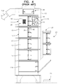
- a conventional centrifugal pellet dryer of the vertical type is generally designated by reference numeral 10 and includes a dryer housing 12 having a sectional screen 14 mounted vertically therein.
- the sectional screen 14 is shown having four approximately equal screen sections 15 aligned vertically and interconnected at 17.
- the screen 14 encloses and is concentric to a bladed rotor, generally designated by reference numeral 16, which includes inclined blades 18.
- the blades 18 include outer edges adjacent the interior surface of the screen sections 15 supported in a manner well known in the art.
- the rotor imparts lift and centrifugal forces to the particles to impact the particles against the screen for separating water from the particles with the separated water passing through the screen into the housing and out through outlet 24 in a manner well known in the art as exemplified by the previously mentioned prior patents.
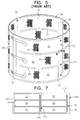
- the two deflector strips shown in Figure 5 are mounted on the inside surface of the cylindrical screen section 15.
- the deflector strips 70 are attached by bolts which protrude through matching holes in the cylindrical screen section 15 on which appropriate locking nuts 74 can be installed to affix each deflector strip 70 in place on the inside of the screen section.
- the deflector strip 70 redirects pellet flow as indicated by the solid arrowed line 75 in Figure 6 , when the rotor 16 turns as indicated by the inner arrow 77.
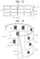
- the embossed deflector strips are vertical or substantially vertical, the embossed deflector strips may be formed at an acute angle relative to the vertical so as to lean away, moving from the bottom of the screen plate 128 to the top thereof, from the direction of the rotor.
- Such an angled embossed deflector strip 270 as illustrated in Figures 12 and 13 , may be used to create a more upward trajectory in the movement of the pellets as they impact against and are redirected toward the rotor by the upwardly inclined edges of the embossed deflectors.
- Vertical and angled deflector strips may also be combined within the same screen as shown in Figure 12 in which the arrow 175 indicates rotor direction.
- embossed deflector strips 170 are preferably continuous raised strips, they could be discontinuous and of smaller length so as to facilitate the required wrapping of the screen around the support rings to obtain the cylindrical configuration. Continuous raised strips are preferred because they tend to provide a continuous length of deflection and to offer a great degree of added stiffening to the cylindrical screen or screen section. As such, it is possible that the embossed strips may allow for a thinner screen plate 128.
- the embossed deflector screen in accordance with the present invention increases the overall efficiency of the pellet dryer and results in considerable savings in terms of capital investment. More particularly, for a dryer of a given size, greater product flow rates can be achieved with the embossed deflector screen than with conventional dryer screens. As a result, a smaller dryer can be used to effectively meet production requirements that would otherwise have required the purchase of a larger dryer. By avoiding the need for this purchase, cost savings on the order of tens and even hundreds of thousands of dollars can be realized.
Landscapes
- Engineering & Computer Science (AREA)
- Mechanical Engineering (AREA)
- General Engineering & Computer Science (AREA)
- Health & Medical Sciences (AREA)
- Life Sciences & Earth Sciences (AREA)
- Molecular Biology (AREA)
- Drying Of Solid Materials (AREA)
- Processing And Handling Of Plastics And Other Materials For Molding In General (AREA)
- Centrifugal Separators (AREA)
Claims (21)
- Sieb für einen Granulatzentrifugaltrockner (10), welcher ein im Wesentlichen zylindrisches Sieb (14) mit einer Innenfläche mit ein oder mehreren Bereichen umfasst, wobei jeder Bereich erhaben ist und nach innen ragt, um ein Umlenkelement (70) zu bilden, das eine Kreisströmung von Partikeln, die getrocknet werden, unterbricht, um eine Partikelströmung durch eine Rotorfläche des Trockners (10) zu verbessern, wobei das Umlenkelement (70) integral mit dem Sieb (14) ist, so dass das Umlenkelement (70) keine von dem Sieb getrennte Komponente ist und sich nicht auf das Gesamtgewicht des Siebs (14) auswirkt, dadurch gekennzeichnet, dass der eine oder die mehreren Bereiche eingeprägt sind.
- Sieb nach Anspruch 1, wobei jeder eingeprägte Bereich einen im Wesentlichen vertikalen erhabenen Umlenkelementstreifen (70) bildet.
- Sieb nach Anspruch 2, wobei das Sieb mehrere eingeprägte Bereiche umfasst, die als im Wesentlichen vertikale Streifen ausgebildet sind, die um die Innenfläche des Siebs (14) herum voneinander beabstandet sind.
- Sieb nach Anspruch 3, wobei die Streifen von angrenzend an einen unteren Rand des Siebs (14) zu angrenzend an einen oberen Rand des Siebs (14) in einer gestaffelten Anordnung angeordnet sind.
- Sieb nach Anspruch 1, wobei das Sieb (14) perforierte und nicht perforierte Flächen umfasst, wobei die eingeprägten Bereiche in den nicht perforierten Flächen ausgebildet sind.
- Sieb nach Anspruch 1, wobei das Sieb (14) perforierte und nicht perforierte Flächen umfasst, wobei die eingeprägten Bereiche in den perforierten Flächen ausgebildet sind.
- Sieb nach Anspruch 1, wobei das integrale Umlenkelement (70) einen gleichmäßig durchgehenden ansteigenden Rand mit angrenzenden nicht erhabenen Abschnitten der Siebinnenfläche aufweist.
- Sieb nach Anspruch 1, wobei das Umlenkelement (70) eingeprägt ist und relativ zu den nicht eingeprägten Abschnitten der Innenfläche um etwa 2,54 mm (0,10 Zoll) bis etwa 6,35 mm (0,25 Zoll) nach innen ragt.
- Sieb nach Anspruch 8, wobei das Umlenkelement (70) eine Breite von etwa 6,35 mm (0,25 Zoll) bis etwa 20,3 mm (0,80 Zoll) aufweist.
- Sieb nach Anspruch 1, wobei sich jeder ein Umlenkelement (70) bildende eingeprägte Bereich im Wesentlichen von einer Oberseite des Siebs zu einer Unterseite desselben erstreckt.
- Granulatzentrifugaltrockner, welcher umfasst: ein Trocknergehäuse (12) mit einem Sieb (14) nach einem der Ansprüche 1 bis 10, wobei das Sieb darin vertikal, im Allgemeinen konzentrisch mit einem mit Blättern versehenen Rotor (16), eingebaut ist, einen Einlass (20) zum Aufnehmen einer Aufschlämmung aus Wasser und Feststoffpartikeln von einem Unterwassergranulator in ein Unterteil des Siebs (14), wobei die Feststoffpartikel in einer Kreissströmung durch das Sieb von dem Rotor (16) nach oben zu einem Auslass (24) an einem oberen Ende des Siebs (14) bewegt werden.
- Trockner nach Anspruch 11, wobei jeder eingeprägte Bereich einen im Wesentlichen vertikalen erhabenen Umlenkelementstreifen (70) bildet.
- Trockner nach Anspruch 12, wobei das Sieb (14) mehrere eingeprägte Bereiche umfasst, die als im Wesentlichen vertikale Umlenkelementstreifen (70) ausgebildet sind, die um die Innenfläche des Siebs (14) herum voneinander beabstandet sind.
- Trockner nach Anspruch 13, wobei die Umlenkelementstreifen (70) von angrenzend an einen unteren Rand des Siebs (70) zu angrenzend an einen oberen Rand desselben in einer gestaffelten Anordnung angeordnet sind.
- Trockner nach Anspruch 12, wobei das Sieb (14) perforierte und nicht perforierte Flächen umfasst, wobei der Umlenkelementstreifen (70) in einem nicht perforierten Bereich eingeprägt ist.
- Trockner nach Anspruch 12, wobei das Sieb (14) perforierte und nicht perforierte Flächen umfasst, wobei der Umlenkelementstreifen (70) in einer perforierten Fläche eingeprägt ist.
- Trockner nach Anspruch 11, wobei das integrale Umlenkelement (70) einen gleichmäßig durchgehenden ansteigenden Rand mit angrenzenden, nicht erhabenen Abschnitten der Siebinnenfläche aufweist.
- Trockner nach Anspruch 13, wobei die Umlenkelementstreifen (70) eine Breite von etwa 6,35 mm (0,25 Zoll) bis etwa 20,3 mm (0,80 Zoll) aufweisen und relativ zu nicht erhabenen Abschnitten der Siebinnenfläche um etwa 2,54 mm (0,10 Zoll) bis etwa 6,35 mm (0,25 Zoll) nach innen ragen.
- Trockner nach Anspruch 13, wobei die Umlenkelementstreifen (70) eine Breite von etwa 15,7 mm (0,62 Zoll) aufweisen und relativ zu nicht erhabenen Abschnitten der Siebinnenfläche um etwa 3,56 mm (0,14 Zoll) nach innen ragen.
- Trockner nach Anspruch 11, wobei das Sieb mehrere miteinander verbundene, vertikal ausgerichtete Siebabschnitte (15) umfasst.
- Sieb nach Anspruch 20, wobei jeder der Siebabschnitte (15) einen einen Umlenkelementstreifen (70) bildenden eingeprägten Bereich so aufweist, dass sich die Umlenkelementstreifen in einer im Wesentlichen durchgehenden Anordnung von einer Oberseite des Trockners zu einer Unterseite desselben erstrecken.
Applications Claiming Priority (2)
| Application Number | Priority Date | Filing Date | Title |
|---|---|---|---|
| US92462707P | 2007-05-23 | 2007-05-23 | |
| PCT/US2008/006522 WO2008147514A1 (en) | 2007-05-23 | 2008-05-22 | Centrifugal pellet dryer screen with integral embossed deflector strips |
Publications (3)
| Publication Number | Publication Date |
|---|---|
| EP2147272A1 EP2147272A1 (de) | 2010-01-27 |
| EP2147272A4 EP2147272A4 (de) | 2014-12-24 |
| EP2147272B1 true EP2147272B1 (de) | 2016-08-17 |
Family
ID=40071068
Family Applications (1)
| Application Number | Title | Priority Date | Filing Date |
|---|---|---|---|
| EP08754632.1A Active EP2147272B1 (de) | 2007-05-23 | 2008-05-22 | Zentrifugales pellettrocknungssieb mit integrierten eingeprägten deflektorstreifen |
Country Status (14)
| Country | Link |
|---|---|
| US (1) | US8220177B2 (de) |
| EP (1) | EP2147272B1 (de) |
| JP (1) | JP5795161B2 (de) |
| KR (1) | KR20100016626A (de) |
| CN (1) | CN102016473B (de) |
| AU (1) | AU2008257407B2 (de) |
| BR (1) | BRPI0812156B1 (de) |
| CA (1) | CA2684414C (de) |
| CO (1) | CO6241181A2 (de) |
| EC (1) | ECSP099746A (de) |
| MX (1) | MX2009012230A (de) |
| MY (1) | MY162101A (de) |
| TW (1) | TWI437198B (de) |
| WO (1) | WO2008147514A1 (de) |
Families Citing this family (15)
| Publication number | Priority date | Publication date | Assignee | Title |
|---|---|---|---|---|
| ATE532615T1 (de) * | 2006-09-20 | 2011-11-15 | Econ Maschb Und Steuerungstechnik Gmbh | Vorrichtung zum entwässern und trocknen von feststoffen, insbesondere von unterwassergranulierten kunststoffen |
| US7579957B2 (en) * | 2006-10-24 | 2009-08-25 | International Business Machines Corporation | Method and apparatus for achieving bi-axial tilt monitoring using a single-axis tilt monitoring device |
| US8220177B2 (en) * | 2007-05-23 | 2012-07-17 | Gala Industries, Inc. | Centrifugal pellet dryer screen with integral embossed deflector strips |
| US9815223B2 (en) | 2008-05-16 | 2017-11-14 | Gala Industries, Inc. | Method and device for extrusion of hollow pellets |
| US8205350B2 (en) | 2008-09-02 | 2012-06-26 | Gala Industries, Inc. | Dryer system with improved throughput |
| JP5680635B2 (ja) | 2009-06-22 | 2015-03-04 | ガラ・インダストリーズ・インコーポレイテッドGala Industries, Inc. | 処理能力が向上したペレット化、乾燥、及び袋詰めの連続システム |
| US8192634B2 (en) | 2009-07-13 | 2012-06-05 | Gilles Stephen R | Centrifugal basket assembly with segmented dam and method |
| RU2410616C1 (ru) * | 2009-09-16 | 2011-01-27 | Открытое акционерное общество "Корпорация "Росхимзащита" (ОАО "Корпорация "Росхимзащита") | Центробежная сушилка |
| USD700411S1 (en) * | 2013-02-07 | 2014-02-25 | Lg Electronics Inc. | Drum for washing machine |
| US20150000152A1 (en) * | 2013-06-26 | 2015-01-01 | Gala Industries, Inc. | Centrifugal pellet dryer screen with integral outwardly projecting deflector strips |
| USD761501S1 (en) | 2013-09-27 | 2016-07-12 | Whirlpool Corporation | Container for clothes washing machine |
| CN107530659B (zh) | 2015-03-05 | 2020-11-13 | 戈拉工业公司 | 回转机构系统和方法 |
| US11077351B2 (en) * | 2018-05-02 | 2021-08-03 | Rapsodo Pte. Ltd. | Measurement and reconstruction of the golf launching scene in 3D |
| WO2020197930A1 (en) * | 2019-03-22 | 2020-10-01 | Gala Industries, Inc. | Methods and systems for crystallizing tacky materials using a tumbler |
| CN111298990A (zh) * | 2019-12-03 | 2020-06-19 | 安徽普源分离机械制造有限公司 | 一种自清洁型离心机转鼓总成 |
Family Cites Families (22)
| Publication number | Priority date | Publication date | Assignee | Title |
|---|---|---|---|---|
| US319572A (en) * | 1885-06-09 | Bolting-reel | ||
| US1721604A (en) | 1927-09-06 | 1929-07-23 | George W Rapp | Signal |
| US2745193A (en) * | 1954-11-17 | 1956-05-15 | Allan L Ladd | Drier |
| US4810270A (en) * | 1985-10-24 | 1989-03-07 | Kimberly-Clark Corporation | Separator |
| US5265347A (en) | 1992-09-04 | 1993-11-30 | Gala Industries, Inc. | Centrifugal pellet dryer |
| CN1060545C (zh) * | 1996-06-01 | 2001-01-10 | 杨建宝 | 整体式双股新水流套桶洗衣机 |
| JPH10180146A (ja) * | 1996-12-27 | 1998-07-07 | Tanabe Uiru Tec Kk | フィルタ装置 |
| GB2328890B (en) * | 1997-09-03 | 2001-08-22 | Glacier Co Ltd | Centrifugal separation apparatus |
| JP2000018821A (ja) * | 1998-07-06 | 2000-01-18 | Matsushita Electric Ind Co Ltd | 脱水乾燥装置 |
| US6582819B2 (en) * | 1998-07-22 | 2003-06-24 | Borden Chemical, Inc. | Low density composite proppant, filtration media, gravel packing media, and sports field media, and methods for making and using same |
| AR019461A1 (es) * | 1998-07-22 | 2002-02-20 | Borden Chem Inc | UNA PARTíCULA COMPUESTA, UN MÉTODO PARA PRODUCIRLA, UN MÉTODO PARA TRATAR UNA FRACTURA HIDRÁULICAMENTE INDUCIDA EN UNA FORMACIoN SUBTERRÁNEA, Y UN MÉTODO PARA LA FILTRACIoN DE AGUA. |
| US6237244B1 (en) | 1998-10-19 | 2001-05-29 | Gala Industries, Inc. | Centrifugal pellet dryer for small applications |
| US6807748B2 (en) | 1999-10-19 | 2004-10-26 | Gala Industries, Inc. | Centrifugal pellet dryer |
| US6698107B2 (en) * | 2001-06-29 | 2004-03-02 | Lg Electronics Inc. | Drum for clothes drier |
| JP3677226B2 (ja) * | 2001-08-06 | 2005-07-27 | 株式会社日本製鋼所 | 樹脂ペレット用遠心脱水乾燥機 |
| US6739457B2 (en) * | 2001-08-17 | 2004-05-25 | Gala Industries, Inc. | Deflector for centrifugal pellet dryer screen |
| CN2525453Y (zh) * | 2001-11-02 | 2002-12-11 | 袁海涛 | 带筛网的烘干筒 |
| CN100519906C (zh) * | 2004-07-26 | 2009-07-29 | 乐金电子(天津)电器有限公司 | 具有螺旋挡板的衣物烘干机 |
| US7024794B1 (en) | 2004-10-15 | 2006-04-11 | Gala Industries | Centrifugal pellet dryer with plastic wall panels |
| US7171762B2 (en) | 2004-10-19 | 2007-02-06 | Gala Industries, Inc. | Self-cleaning centrifugal pellet dryer and method thereof |
| DE202007004462U1 (de) * | 2007-03-19 | 2008-07-31 | Gala Kunststoff- Und Kautschukmaschinen Gmbh | Zentrifugaltrockner |
| US8220177B2 (en) * | 2007-05-23 | 2012-07-17 | Gala Industries, Inc. | Centrifugal pellet dryer screen with integral embossed deflector strips |
-
2008
- 2008-04-15 US US12/081,396 patent/US8220177B2/en active Active
- 2008-05-16 TW TW097118097A patent/TWI437198B/zh active
- 2008-05-22 KR KR1020097023954A patent/KR20100016626A/ko not_active Ceased
- 2008-05-22 WO PCT/US2008/006522 patent/WO2008147514A1/en not_active Ceased
- 2008-05-22 AU AU2008257407A patent/AU2008257407B2/en not_active Ceased
- 2008-05-22 MX MX2009012230A patent/MX2009012230A/es active IP Right Grant
- 2008-05-22 BR BRPI0812156-7A patent/BRPI0812156B1/pt active IP Right Grant
- 2008-05-22 CA CA2684414A patent/CA2684414C/en active Active
- 2008-05-22 EP EP08754632.1A patent/EP2147272B1/de active Active
- 2008-05-22 JP JP2010509377A patent/JP5795161B2/ja active Active
- 2008-05-22 MY MYPI20094686A patent/MY162101A/en unknown
- 2008-05-22 CN CN2008800167394A patent/CN102016473B/zh active Active
-
2009
- 2009-11-19 EC EC2009009746A patent/ECSP099746A/es unknown
- 2009-11-23 CO CO09133052A patent/CO6241181A2/es active IP Right Grant
Also Published As
| Publication number | Publication date |
|---|---|
| US20080289208A1 (en) | 2008-11-27 |
| CO6241181A2 (es) | 2011-01-20 |
| US8220177B2 (en) | 2012-07-17 |
| AU2008257407B2 (en) | 2013-05-09 |
| BRPI0812156B1 (pt) | 2020-09-08 |
| TW200912231A (en) | 2009-03-16 |
| MY162101A (en) | 2017-05-31 |
| WO2008147514A1 (en) | 2008-12-04 |
| CA2684414C (en) | 2014-07-15 |
| EP2147272A4 (de) | 2014-12-24 |
| BRPI0812156A2 (pt) | 2014-11-18 |
| CN102016473A (zh) | 2011-04-13 |
| CA2684414A1 (en) | 2008-12-04 |
| AU2008257407A1 (en) | 2008-12-04 |
| EP2147272A1 (de) | 2010-01-27 |
| TWI437198B (zh) | 2014-05-11 |
| CN102016473B (zh) | 2013-05-01 |
| JP5795161B2 (ja) | 2015-10-14 |
| ECSP099746A (es) | 2010-04-30 |
| JP2010529396A (ja) | 2010-08-26 |
| KR20100016626A (ko) | 2010-02-12 |
| MX2009012230A (es) | 2009-12-01 |
Similar Documents
| Publication | Publication Date | Title |
|---|---|---|
| CA2684414C (en) | Centrifugal pellet dryer screen with integral embossed deflector strips | |
| US6739457B2 (en) | Deflector for centrifugal pellet dryer screen | |
| CN112295886A (zh) | 用于分离固体材料的盘形筛 | |
| US12427688B2 (en) | Impellers for cutting machines and cutting machines equipped with impellers | |
| US11897158B2 (en) | Impellers for cutting machines and cutting machines equipped therewith | |
| US6438866B1 (en) | Flow disrupter for dryers | |
| EP3014206B1 (de) | Zentrifugales pelletreinigungssieb mit integrierten nach aussen weisenden deflektorstreifen | |
| US11643779B2 (en) | Refiner plate having grooves imparting rotational flow to feed material | |
| AU2020473992B2 (en) | Impellers for cutting machines and cutting machines equipped therewith | |
| RU2783533C1 (ru) | Центробежный дисковый измельчитель |
Legal Events
| Date | Code | Title | Description |
|---|---|---|---|
| PUAI | Public reference made under article 153(3) epc to a published international application that has entered the european phase |
Free format text: ORIGINAL CODE: 0009012 |
|
| 17P | Request for examination filed |
Effective date: 20091027 |
|
| AK | Designated contracting states |
Kind code of ref document: A1 Designated state(s): AT BE BG CH CY CZ DE DK EE ES FI FR GB GR HR HU IE IS IT LI LT LU LV MC MT NL NO PL PT RO SE SI SK TR |
|
| AX | Request for extension of the european patent |
Extension state: AL BA MK RS |
|
| DAX | Request for extension of the european patent (deleted) | ||
| A4 | Supplementary search report drawn up and despatched |
Effective date: 20141121 |
|
| RIC1 | Information provided on ipc code assigned before grant |
Ipc: F26B 5/08 20060101AFI20141117BHEP Ipc: F26B 17/24 20060101ALI20141117BHEP |
|
| GRAP | Despatch of communication of intention to grant a patent |
Free format text: ORIGINAL CODE: EPIDOSNIGR1 |
|
| RIC1 | Information provided on ipc code assigned before grant |
Ipc: F26B 17/24 20060101ALI20151016BHEP Ipc: F26B 5/08 20060101AFI20151016BHEP |
|
| INTG | Intention to grant announced |
Effective date: 20151120 |
|
| GRAP | Despatch of communication of intention to grant a patent |
Free format text: ORIGINAL CODE: EPIDOSNIGR1 |
|
| INTG | Intention to grant announced |
Effective date: 20160506 |
|
| GRAS | Grant fee paid |
Free format text: ORIGINAL CODE: EPIDOSNIGR3 |
|
| GRAA | (expected) grant |
Free format text: ORIGINAL CODE: 0009210 |
|
| AK | Designated contracting states |
Kind code of ref document: B1 Designated state(s): AT BE BG CH CY CZ DE DK EE ES FI FR GB GR HR HU IE IS IT LI LT LU LV MC MT NL NO PL PT RO SE SI SK TR |
|
| REG | Reference to a national code |
Ref country code: GB Ref legal event code: FG4D |
|
| REG | Reference to a national code |
Ref country code: CH Ref legal event code: EP |
|
| REG | Reference to a national code |
Ref country code: IE Ref legal event code: FG4D |
|
| REG | Reference to a national code |
Ref country code: AT Ref legal event code: REF Ref document number: 821509 Country of ref document: AT Kind code of ref document: T Effective date: 20160915 |
|
| REG | Reference to a national code |
Ref country code: DE Ref legal event code: R096 Ref document number: 602008045731 Country of ref document: DE |
|
| REG | Reference to a national code |
Ref country code: NL Ref legal event code: FP |
|
| REG | Reference to a national code |
Ref country code: LT Ref legal event code: MG4D |
|
| PG25 | Lapsed in a contracting state [announced via postgrant information from national office to epo] |
Ref country code: NO Free format text: LAPSE BECAUSE OF FAILURE TO SUBMIT A TRANSLATION OF THE DESCRIPTION OR TO PAY THE FEE WITHIN THE PRESCRIBED TIME-LIMIT Effective date: 20161117 Ref country code: HR Free format text: LAPSE BECAUSE OF FAILURE TO SUBMIT A TRANSLATION OF THE DESCRIPTION OR TO PAY THE FEE WITHIN THE PRESCRIBED TIME-LIMIT Effective date: 20160817 Ref country code: LT Free format text: LAPSE BECAUSE OF FAILURE TO SUBMIT A TRANSLATION OF THE DESCRIPTION OR TO PAY THE FEE WITHIN THE PRESCRIBED TIME-LIMIT Effective date: 20160817 Ref country code: FI Free format text: LAPSE BECAUSE OF FAILURE TO SUBMIT A TRANSLATION OF THE DESCRIPTION OR TO PAY THE FEE WITHIN THE PRESCRIBED TIME-LIMIT Effective date: 20160817 |
|
| PG25 | Lapsed in a contracting state [announced via postgrant information from national office to epo] |
Ref country code: LV Free format text: LAPSE BECAUSE OF FAILURE TO SUBMIT A TRANSLATION OF THE DESCRIPTION OR TO PAY THE FEE WITHIN THE PRESCRIBED TIME-LIMIT Effective date: 20160817 Ref country code: SE Free format text: LAPSE BECAUSE OF FAILURE TO SUBMIT A TRANSLATION OF THE DESCRIPTION OR TO PAY THE FEE WITHIN THE PRESCRIBED TIME-LIMIT Effective date: 20160817 Ref country code: ES Free format text: LAPSE BECAUSE OF FAILURE TO SUBMIT A TRANSLATION OF THE DESCRIPTION OR TO PAY THE FEE WITHIN THE PRESCRIBED TIME-LIMIT Effective date: 20160817 Ref country code: PL Free format text: LAPSE BECAUSE OF FAILURE TO SUBMIT A TRANSLATION OF THE DESCRIPTION OR TO PAY THE FEE WITHIN THE PRESCRIBED TIME-LIMIT Effective date: 20160817 Ref country code: GR Free format text: LAPSE BECAUSE OF FAILURE TO SUBMIT A TRANSLATION OF THE DESCRIPTION OR TO PAY THE FEE WITHIN THE PRESCRIBED TIME-LIMIT Effective date: 20161118 Ref country code: PT Free format text: LAPSE BECAUSE OF FAILURE TO SUBMIT A TRANSLATION OF THE DESCRIPTION OR TO PAY THE FEE WITHIN THE PRESCRIBED TIME-LIMIT Effective date: 20161219 |
|
| PG25 | Lapsed in a contracting state [announced via postgrant information from national office to epo] |
Ref country code: EE Free format text: LAPSE BECAUSE OF FAILURE TO SUBMIT A TRANSLATION OF THE DESCRIPTION OR TO PAY THE FEE WITHIN THE PRESCRIBED TIME-LIMIT Effective date: 20160817 Ref country code: RO Free format text: LAPSE BECAUSE OF FAILURE TO SUBMIT A TRANSLATION OF THE DESCRIPTION OR TO PAY THE FEE WITHIN THE PRESCRIBED TIME-LIMIT Effective date: 20160817 |
|
| REG | Reference to a national code |
Ref country code: DE Ref legal event code: R097 Ref document number: 602008045731 Country of ref document: DE |
|
| PG25 | Lapsed in a contracting state [announced via postgrant information from national office to epo] |
Ref country code: BG Free format text: LAPSE BECAUSE OF FAILURE TO SUBMIT A TRANSLATION OF THE DESCRIPTION OR TO PAY THE FEE WITHIN THE PRESCRIBED TIME-LIMIT Effective date: 20161117 Ref country code: SK Free format text: LAPSE BECAUSE OF FAILURE TO SUBMIT A TRANSLATION OF THE DESCRIPTION OR TO PAY THE FEE WITHIN THE PRESCRIBED TIME-LIMIT Effective date: 20160817 Ref country code: DK Free format text: LAPSE BECAUSE OF FAILURE TO SUBMIT A TRANSLATION OF THE DESCRIPTION OR TO PAY THE FEE WITHIN THE PRESCRIBED TIME-LIMIT Effective date: 20160817 |
|
| PLBE | No opposition filed within time limit |
Free format text: ORIGINAL CODE: 0009261 |
|
| STAA | Information on the status of an ep patent application or granted ep patent |
Free format text: STATUS: NO OPPOSITION FILED WITHIN TIME LIMIT |
|
| 26N | No opposition filed |
Effective date: 20170518 |
|
| PG25 | Lapsed in a contracting state [announced via postgrant information from national office to epo] |
Ref country code: SI Free format text: LAPSE BECAUSE OF FAILURE TO SUBMIT A TRANSLATION OF THE DESCRIPTION OR TO PAY THE FEE WITHIN THE PRESCRIBED TIME-LIMIT Effective date: 20160817 Ref country code: LU Free format text: LAPSE BECAUSE OF NON-PAYMENT OF DUE FEES Effective date: 20170531 |
|
| REG | Reference to a national code |
Ref country code: CH Ref legal event code: PL |
|
| GBPC | Gb: european patent ceased through non-payment of renewal fee |
Effective date: 20170522 |
|
| PG25 | Lapsed in a contracting state [announced via postgrant information from national office to epo] |
Ref country code: MC Free format text: LAPSE BECAUSE OF FAILURE TO SUBMIT A TRANSLATION OF THE DESCRIPTION OR TO PAY THE FEE WITHIN THE PRESCRIBED TIME-LIMIT Effective date: 20160817 |
|
| REG | Reference to a national code |
Ref country code: IE Ref legal event code: MM4A |
|
| PG25 | Lapsed in a contracting state [announced via postgrant information from national office to epo] |
Ref country code: CH Free format text: LAPSE BECAUSE OF NON-PAYMENT OF DUE FEES Effective date: 20170531 Ref country code: LI Free format text: LAPSE BECAUSE OF NON-PAYMENT OF DUE FEES Effective date: 20170531 |
|
| REG | Reference to a national code |
Ref country code: FR Ref legal event code: ST Effective date: 20180131 |
|
| PG25 | Lapsed in a contracting state [announced via postgrant information from national office to epo] |
Ref country code: LU Free format text: LAPSE BECAUSE OF NON-PAYMENT OF DUE FEES Effective date: 20170522 |
|
| PG25 | Lapsed in a contracting state [announced via postgrant information from national office to epo] |
Ref country code: GB Free format text: LAPSE BECAUSE OF NON-PAYMENT OF DUE FEES Effective date: 20170522 Ref country code: IE Free format text: LAPSE BECAUSE OF NON-PAYMENT OF DUE FEES Effective date: 20170522 |
|
| PG25 | Lapsed in a contracting state [announced via postgrant information from national office to epo] |
Ref country code: FR Free format text: LAPSE BECAUSE OF NON-PAYMENT OF DUE FEES Effective date: 20170531 |
|
| PG25 | Lapsed in a contracting state [announced via postgrant information from national office to epo] |
Ref country code: MT Free format text: LAPSE BECAUSE OF NON-PAYMENT OF DUE FEES Effective date: 20170522 |
|
| PG25 | Lapsed in a contracting state [announced via postgrant information from national office to epo] |
Ref country code: HU Free format text: LAPSE BECAUSE OF FAILURE TO SUBMIT A TRANSLATION OF THE DESCRIPTION OR TO PAY THE FEE WITHIN THE PRESCRIBED TIME-LIMIT; INVALID AB INITIO Effective date: 20080522 |
|
| REG | Reference to a national code |
Ref country code: AT Ref legal event code: UEP Ref document number: 821509 Country of ref document: AT Kind code of ref document: T Effective date: 20160817 |
|
| PG25 | Lapsed in a contracting state [announced via postgrant information from national office to epo] |
Ref country code: CY Free format text: LAPSE BECAUSE OF NON-PAYMENT OF DUE FEES Effective date: 20160817 |
|
| PG25 | Lapsed in a contracting state [announced via postgrant information from national office to epo] |
Ref country code: TR Free format text: LAPSE BECAUSE OF FAILURE TO SUBMIT A TRANSLATION OF THE DESCRIPTION OR TO PAY THE FEE WITHIN THE PRESCRIBED TIME-LIMIT Effective date: 20160817 |
|
| PG25 | Lapsed in a contracting state [announced via postgrant information from national office to epo] |
Ref country code: IS Free format text: LAPSE BECAUSE OF FAILURE TO SUBMIT A TRANSLATION OF THE DESCRIPTION OR TO PAY THE FEE WITHIN THE PRESCRIBED TIME-LIMIT Effective date: 20161217 |
|
| PGFP | Annual fee paid to national office [announced via postgrant information from national office to epo] |
Ref country code: NL Payment date: 20250521 Year of fee payment: 18 |
|
| PGFP | Annual fee paid to national office [announced via postgrant information from national office to epo] |
Ref country code: DE Payment date: 20250521 Year of fee payment: 18 |
|
| PGFP | Annual fee paid to national office [announced via postgrant information from national office to epo] |
Ref country code: BE Payment date: 20250521 Year of fee payment: 18 Ref country code: IT Payment date: 20250527 Year of fee payment: 18 |
|
| PGFP | Annual fee paid to national office [announced via postgrant information from national office to epo] |
Ref country code: AT Payment date: 20250522 Year of fee payment: 18 |
|
| PGFP | Annual fee paid to national office [announced via postgrant information from national office to epo] |
Ref country code: CZ Payment date: 20250514 Year of fee payment: 18 |