EP2146889B1 - Arrangement for a steering column of a commercial vehicle - Google Patents
Arrangement for a steering column of a commercial vehicle Download PDFInfo
- Publication number
- EP2146889B1 EP2146889B1 EP08749739A EP08749739A EP2146889B1 EP 2146889 B1 EP2146889 B1 EP 2146889B1 EP 08749739 A EP08749739 A EP 08749739A EP 08749739 A EP08749739 A EP 08749739A EP 2146889 B1 EP2146889 B1 EP 2146889B1
- Authority
- EP
- European Patent Office
- Prior art keywords
- steering column
- steering
- housing
- bearing block
- height
- Prior art date
- Legal status (The legal status is an assumption and is not a legal conclusion. Google has not performed a legal analysis and makes no representation as to the accuracy of the status listed.)
- Not-in-force
Links
Images


Classifications
-
- B—PERFORMING OPERATIONS; TRANSPORTING
- B62—LAND VEHICLES FOR TRAVELLING OTHERWISE THAN ON RAILS
- B62D—MOTOR VEHICLES; TRAILERS
- B62D1/00—Steering controls, i.e. means for initiating a change of direction of the vehicle
- B62D1/02—Steering controls, i.e. means for initiating a change of direction of the vehicle vehicle-mounted
- B62D1/16—Steering columns
- B62D1/18—Steering columns yieldable or adjustable, e.g. tiltable
- B62D1/183—Steering columns yieldable or adjustable, e.g. tiltable adjustable between in-use and out-of-use positions, e.g. to improve access
-
- B—PERFORMING OPERATIONS; TRANSPORTING
- B62—LAND VEHICLES FOR TRAVELLING OTHERWISE THAN ON RAILS
- B62D—MOTOR VEHICLES; TRAILERS
- B62D1/00—Steering controls, i.e. means for initiating a change of direction of the vehicle
- B62D1/02—Steering controls, i.e. means for initiating a change of direction of the vehicle vehicle-mounted
- B62D1/16—Steering columns
- B62D1/18—Steering columns yieldable or adjustable, e.g. tiltable
- B62D1/184—Mechanisms for locking columns at selected positions
-
- B—PERFORMING OPERATIONS; TRANSPORTING
- B62—LAND VEHICLES FOR TRAVELLING OTHERWISE THAN ON RAILS
- B62D—MOTOR VEHICLES; TRAILERS
- B62D1/00—Steering controls, i.e. means for initiating a change of direction of the vehicle
- B62D1/02—Steering controls, i.e. means for initiating a change of direction of the vehicle vehicle-mounted
- B62D1/16—Steering columns
- B62D1/18—Steering columns yieldable or adjustable, e.g. tiltable
- B62D1/187—Steering columns yieldable or adjustable, e.g. tiltable with tilt adjustment; with tilt and axial adjustment
Definitions
- the invention relates to an arrangement for a steering column of a utility vehicle according to the preamble of claim 1.
- the need for intelligent solutions is particularly great for commercial vehicles in distribution traffic, where the driver often has to get in and out.
- the easy-entry function should make it possible for the driver to pivot the steering wheel completely forwards in order to bring the steering wheel into a horizontal position or parking position in order to obtain the greatest possible clearance through the cabin.
- a simply constructed and immediately acting memory function is to be made available in order to be able to swivel the steering wheel back into its original position (driving position) quickly and accurately after boarding.
- the WO 2006/108631 A1 discloses a gattengsgemabe steering column, which can assume a different position in the event of a frontal impact to protect the driver.
- a steering shaft is rotatably mounted in the coupling of a transmission chain, the two links are hinged in their lower areas on steering joints to stationary vehicle parts.
- the geometry of the transmission chain is designed so that when driving in the event of a head-on collision, the steering wheel level increases its inclination closer to the vertical.
- the steering wheel for use state by means of adjustment in height and tilt is adjustable by the coupling accordingly is adjustable, by adjusting the length of at least one of the links and / or by displacement of at least one linkage.
- the DE 40 16 163 A1 shows a device that makes it possible to pivot the steering column from an individually set driving position in a the entry and exit favoring angular position.
- a swingarm is set on the bearing housing, the one equipped with a catch, pivotally mounted lever which engages behind a latching surface of a stationary bearing block in the operating position of the steering column.
- a locking device which comprises a coupled to the lower steering column part segment part with a toothing and with this toothing manually engageable coupled to the upper steering column part pawl.
- WO 2007/058362 A1 discloses a steering column system in which a steering column is fixed by means of a Zahneingreiffunktion by a steering position adjustment operating lever relative to a body.
- an arrangement for a steering column of a commercial vehicle with a bearing block in which an upper steering column housing is adjustably mounted for a steering shaft, wherein the bearing block has first guide and fastening means to adjust the height of the steering column housing adjustable in height, and second guide and fastening means for adjustably fixing the steering column housing in its inclination, wherein the second guide and fastening means comprise a lever arm which is adjustably attached to the bearing block at a lower end and has a toothed recess at an upper end, into which a toothed element connected to the steering column housing engages. The toothed element in turn is connected directly or via a connecting arm or lever to the steering column housing.
- the arrangement may preferably be implemented in the manner of a modular system which is a flexible, usable construction for various applications, such as e.g. for a rigid steering column, for a steering column adjustable only in the steering wheel angle or for a height-adjustable and swiveling steering column.
- the lever arm has at its lower end a round hole or a curved slot, which is provided for an adjustment of the inclination and in which a connectable to the upper steering column housing second clamping or screw is fixedly received.
- a lower stop for the toothed element is defined by a fixation of the lever arm by means of the second screw or clamping element and by a lower end of the recess, at least in the direction of inclination one for driving optimally on the Driver set steering wheel position determines.
- the mechanical stop may still be provided with a damping element, e.g. a plastic element, be provided.
- the maximum pivoting range is defined forward by an upper stop attached to the guide plate, which determines a maximum adjustable steering wheel position, at least in the direction of inclination, for the driver's entry and exit. This increases u.a. the safety of the easy-entry function, because the steering wheel in a well-defined entry position, e.g. horizontal position, can be brought.
- the toothed element connected to the steering column housing which engages in the recess at the upper end of the lever arm, has a fixing element, in particular an eccentric lock or eccentric lever. This makes operation of the easy-entry function particularly easy, yet fast and reliable.
- the bearing block of two main housing parts in particular of two flange halves mounted.
- the bearing block is thus executed in several pieces, and thus a very flexible modular system is created.
- the first guide and fastening means have at least one guide rail, in which a guide plate of the steering column housing is slidably received in height.
- This guide is particularly accurate and reliable.
- first and second guide and fastening means clamping screws and / or at least one clamping device, in particular a pneumatic and / or hydraulic pressure piston or an electromechanical clamping device having.
- an easy-to-use fixation is achieved in a relatively cost-effective manner, which can be locked and released very quickly and easily, for example via a mechanical and / or electrical switch or push-button.
- the Fig. 1 shows an inventive arrangement with a rigidly mounted steering column.
- the arrangement comprises a bearing block 1, which is modularly composed in the manner of a modular system essentially of two flange-shaped housing halves 1 a and 1 b. These are also referred to below with flange halves 1a and 1b.
- an upper steering column housing 11 for a steering shaft 10 is adjustably mounted in the bearing block 1.
- the bearing block 1 has first guide and fastening means to which guide rails 2 belong, in each of which a guide plate 12 of the steering column housing 11 is guided and held alongside.
- a slot 4 is provided in each flange half 1a or 1b, which also belongs to the first guiding and fastening means and is aligned in the direction of the height H to be set.
- a first clamping or screw element is guided in the form of a clamping screw KS and can e.g. Workshop fixed in the desired height setting or fixed.
- the in the Fig. 1 arrangement shown also has second guide and fastening means, in particular a lever arm 5 with a recess 5a, in which a toothed element 6a engages.
- the lever arm 5 is adjustably fixed to the bearing block 1 at a lower end.
- the lever arm 5 at its lower end a round hole or preferably a curved slot 5b, which in the adjustment of Tilt N serves as a fulcrum or guide.
- a second clamping or screwing element such as a further clamping screw KS ', received in the round or slot fixed and can then be tightened at the desired angle of inclination.
- a lower stop 7 is defined for the toothed element 6a, at least in the direction of inclination N optimally set for the driving operation on the driver steering wheel position certainly.
- a construction variant of the arrangement shows the Fig. 2 in which the toothed element 6a can be released and fixed again more easily and quickly within the toothed recess 5a.
- an eccentric lever EH is attached to the toothed element 6a or to the clamping screw KS provided there, with which the toothing and clamping can be released very quickly manually, for example by the driver himself, and fixed again.
- the toothing is closer in the detail representation after Fig. 3 shown. As can be seen there, the toothing is located at least on an inner edge of the recess 5 a provided on the lever arm 5 a.
- the toothing can be realized in the form of a toothed or corrugated surface, a row of teeth or similar features, which can cause at least a friction or preferably even a hooking with the toothed element 6a.
- the toothed element 6a is suitably formed in the form of a guided in the recess 5a or moving piece, which is also interlocked or corrugated.
- the toothed element 6a and thus also the associated arm or lever 6 can be moved, which determines the inclination position of the steering column housing or the steering column (see also Fig. 2 ).
- the teeth ensure that after the pivoting of the steering column, these can not inadvertently swing back down, but engages in the teeth.
- the inclination N of the steering column can be easily and quickly adjusted manually and, in particular, brought into an easy-entry position.
- the bottom stop 7 defined in the recess 5a causes the steering wheel to be returned exactly to the desired driving position, which in turn is determined by the basic setting of the lever arm 5.
- this construction results in a mechanical memory function in combination with an easy-to-use easy-to-use function.
- the steering wheel angle N can be set very quickly and effectively to the easy-entry position or parking position and brought back into the exact driving position.
- a toothed element 6a with an eccentric EH and other fastening or adjusting means can be used.
- Conceivable here are e.g. Fasteners that can be moved by cable, pneumatically with compressed air, electrically with motor or even moved hydraulically and by another form of energy and can be solved.
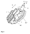
- the Fig. 4 shows a further embodiment in the form of a continuously variable in height H and tilt N adjustable steering column assembly.
- the adjustment happens here on the one hand by means of a clamping device KE, which clamps the guide plate 12 and the lever arm 5 against the bearing block 1 or releases for adjusting the steering column.
- This clamping device KE is here preferably a compressed air cylinder, but may also be any other form of clamping device, such as an eccentric lever or a cable, a pneumatically with compressed air, a powered electrically by a motor, a hydraulic or by another form of energy device or each be other releasable clamping or clamping means.
- the toothed element 6a is clamped and fixed with a screw KS ".
- Fig. 5 are shown in a transverse view of the various steering wheel positions, which can be adjusted very quickly and easily by the inventive solution.
- the Fig. 5 refers in particular to the embodiments in which the toothed element 6a is clamped or released by means of eccentric lever EH.
- the height adjustment H essentially by the in the slot 4 of the bearing block 1 guided screw KS is fixed and determined.
- the inclination N in turn is essentially determined by the fixing of the lever arm 5 on the bearing block 1 itself (clamping screw KS ') and by the current position of the adjustable toothing (toothed element 6a), which can be preferably solved by the eccentric lever EH.
- the Fig. 6 shows as a further embodiment, a steplessly adjustable in height and tilt steering column, which has a particularly user-friendly design and is also equipped with easy-entry function and memory function.
- a clamping device KE is provided, which clamps the guide plate 12 and the lever arm 5 against the bearing block 1 and releases for adjusting the steering column.
- an eccentric lever EH is provided to immediately release the upper steering column, if necessary, so that it can be pivoted forward in a vertical position, namely in the easy-entry position or parking position.
- This parking position PE is in the Fig. 7 even more clearly shown, where it can also be seen that for pivoting the steering wheel, an upper stop 8 can be provided, which defines the maximum parking position.
- an upper stop 8 can be provided, which defines the maximum parking position.
- the driver after boarding the steering wheel can then be swung down to the lower stop 7 again.
- the lower stop 7 and the basic setting or basic fixing of the lever arm 5 on the bearing block itself define the driving position or the previously set steering wheel position PD according to the memory function.
- the presented invention is a particularly simple but effective arrangement for fast steering column adjustment or steering wheel adjustment in commercial vehicles proposed.
- the memory function can also be realized purely mechanically and therefore also particularly cost. It achieves the fastest possible return to the original driving position without influencing the driver-side basic setting of the steering column in terms of height and inclination.
- the arrangement is realized and offered in the modular principle, which means that the steering column assembly can be designed in a variety of variants or used for a variety of applications, such as in the cost-optimized version as a rigid (adjustable but not adjustable) steering column or in a more comfortable version, in which the steering wheel angle is adjustable at least in height.
- the steering wheel position is designed to be adjustable in height and in inclination, whereby memory function and easy-entry function in the manner described above act combined with each other.
- the settings are very easy to use:
- the toothed element is released and the steering wheel pivoted all the way to the front.
- the toothing serves the form-fitting, to avoid high clamping forces; the clamping as a superposition of a frictional connection also serves to conceal the game in the toothing, i. Unacceptable play becomes elasticity.
- the steering wheel When retracting the steering wheel in the memory position, the steering wheel is pulled down to the stop and so brought back to its previous position. This results in particular two pivoting possibilities in a guide plate, namely the adjustment / adjustment of the steering wheel position per se and the adjustment to bring the steering wheel forward in the easy-entry position and again exactly back into the memory position.
Abstract
Description
Die Erfindung betrifft eine Anordnung für eine Lenksäule eines Nutzfahrzeuges nach dem Oberbegriff des Anspruchs 1.The invention relates to an arrangement for a steering column of a utility vehicle according to the preamble of
Unter den bekannten Anordnungen für Lenksäulen von Nutzfahrzeugen gibt es hauptsächlich zwei verschiedene Varianten. Zum einen handelt es sich um einfache Konstruktionen mit einer starr eingestellten Lenksäule. Die Höhe bzw. Neigung der Lenksäule kann hierbei nur während der Montage der Lenksäule eingestellt und später nicht mehr verändert bzw. verstellt werden. Zum anderen handelt es sich um Konstruktionen, bei denen die Lenksäule und somit auch das Lenkrad vom Fahrer selbst für den Fahrbetrieb in der Höhe und/oder in der Neigung verstellt werden kann Insbesondere zum Einstieg in das Fahrzeug bzw. beim Ausstieg kann das Lenkrad in eine angenehme Einstiegsstellung, die sog. Easy-Entry-Position, gebracht werden. Dabei wird im Stillstand des Fahrzeugs (Parkposition) das Lenkrad vom Fahrer weggeschwenkt, so dass er bequemer ein- und aussteigen kann. Jedoch muss beim Zurückstellen der Lenksäule in die eigentliche Fahrposition immer die ursprünglich eingestellte Neigung und evtl. auch die eingestellte Höhe des Lenkrades gesucht werden. Wünschenswert wäre es, hier eine automatische Erinnerungsfunktion, eine sog. Memory-Funktion, zu haben, d.h. eine Funktion, die es erlaubt, dass der Fahrer das Lenkrad wieder schnell in die für ihn eingestellte Fahrposition zurückführen kann.Among the known arrangements for steering columns of commercial vehicles, there are mainly two different variants. On the one hand, these are simple constructions with a rigidly adjusted steering column. The height or inclination of the steering column can be adjusted only during assembly of the steering column and later not changed or adjusted. On the other hand, there are constructions in which the steering column and thus the steering wheel can be adjusted by the driver himself for driving in height and / or in inclination in particular for entry into the vehicle or when exiting the steering wheel in a pleasant entry position, the so-called. Easy entry position, brought. In this case, the steering wheel is pivoted away from the driver when the vehicle (parking position), so that he can get on and off comfortably. However, when returning the steering column in the actual driving position always the originally set inclination and possibly also the set height of the steering wheel must be searched. It would be desirable to have here an automatic reminder function, a so-called memory function, i. a function that allows the driver to quickly return the steering wheel to the driving position set for him.
Im Bereich von Personenkraftfahrzeugen (PKW) sind Anordnungen mit elektromotorisch betriebenen Einstellhilfen bekannt, die u.a. auch dafür sorgen, dass die Lenkradstellung automatisch verstellt und in vorprogrammierte Positionen bewegt werden kann. Bei diesen bekannten Anordnungen ist also die Memory-Funktion recht aufwendig und kostenintensiv realisiert. Weil hierzu in der Regel elektrische Stellmotoren mit Getriebe eingesetzt werden, ist die Bewegungs- bzw. Verstellgeschwindigkeit recht langsam. Daher sind diese im PKW-Bereich eingesetzten Lösungen für den praktischen Einsatz im Nutzfahrzeugbereich (NKW-Bereich) schlecht geeignet. Denn dort können solche keine längeren Bewegungs- und Verstellzeiten akzeptiert werden.In the field of passenger vehicles (cars) arrangements with electric motor-operated adjustment aids are known, among other things, ensure that the steering wheel position can be adjusted automatically and moved to preprogrammed positions. In these known arrangements so the memory function is quite complicated and costly realized. Because this usually electrical servomotors are used with gearbox, the movement or adjustment speed is quite slow. Therefore, these solutions are used in the car sector for practical use in the Commercial vehicle sector (commercial vehicle area) poorly suited. Because there such no longer movement and Verstellzeiten be accepted.
Der Bedarf für intelligente Lösungen ist besonders groß für NKW im Verteilerverkehr, bei denen der Fahrer oftmals ein- und aussteigen muss. Hier besteht der große Wunsch nach einer Anordnung, welche die Easy-Entry-Funktion in Verbindung mit einer Memory-Funktion schnell und einfach realisiert. Dabei soll zum einen die Easy-Entry-Funktion es ermöglichen, dass der Fahrer das Lenkrad ganz nach vorne wegschwenken kann, um das Lenkrad in eine horizontale Stellung bzw. Parkposition zu bringen, um somit einen größtmöglichen Freigang durch die Kabine zu bekommen. Zum anderen soll eine einfach konstruierte und sofort wirkende Memory-Funktion zur Verfügung gestellt werden, um dann nach dem Einsteigen das Lenkrad wieder schnell und exakt in seine ursprüngliche Stellung (Fahrposition) zurückschwenken zu können.The need for intelligent solutions is particularly great for commercial vehicles in distribution traffic, where the driver often has to get in and out. Here is the great desire for an arrangement that realizes the easy-entry function in conjunction with a memory function quickly and easily. On the one hand, the easy-entry function should make it possible for the driver to pivot the steering wheel completely forwards in order to bring the steering wheel into a horizontal position or parking position in order to obtain the greatest possible clearance through the cabin. On the other hand, a simply constructed and immediately acting memory function is to be made available in order to be able to swivel the steering wheel back into its original position (driving position) quickly and accurately after boarding.
Dabei soll der Umstand berücksichtigt werden, dass insbesondere im NKW-Bereich die Verstellbereiche der Lenksäule deutlich größer als im PKW-Bereich sind.The fact should be taken into account that, especially in the commercial vehicle sector, the adjustment of the steering column are significantly larger than in the car sector.
Die
Die
Auch die
Schließlich wird in der
Es hat sich also gezeigt, dass im NKW-Bereich herkömmliche Anordnungen mit elektromotorischer Betätigung nicht ausreichen. Insbesondere würde sich die Lenksäule nur sehr langsam in seine Ausgangsposition zurück bewegen und dazu viel Zeit benötigen. Diese Zeit kann sich der Fahrer eines NKW nicht nehmen, gerade auch im Hinblick auf das häufige Ein- und Aussteigen im innerstädtischen Bereich beim sog. "Parken in zweiter Reihe". Gerade hier besteht das Erfordernis für eine Lösung, die es ermöglicht, das Lenkrad nach dem Einstieg in das Fahrzeug sehr schnell wieder in seine vordefinierte Ausgangs-Stellung zurück bewegen zu können. Es besteht somit der Wunsch nach einer kostengünstigen und effektiven Lösung, die beide Funktionen, also Memory-Funktion und Easy-Entry-Funktion, in einer besonders für den NKW-Bereich vorteilhaften Weise miteinander kombiniert.It has thus been shown that conventional arrangements with electromotive actuation are not sufficient in the commercial vehicle sector. In particular, the steering column would move back to its original position only very slowly and take a lot of time to do so. This time can not take the driver of a commercial vehicle, especially in view of the frequent entry and exit in the inner city area in the so-called. "Parking in second row". Especially here there is the need for a solution that makes it possible to very quickly move the steering wheel back into its predefined starting position after getting into the vehicle. There is thus the desire for a cost-effective and effective solution that combines both functions, ie memory function and easy-entry function, in a particularly advantageous for the commercial vehicle sector way together.
Es ist daher Aufgabe der vorliegenden Erfindung, eine verbesserte Lösung vorzuschlagen, die in vorteilhafter Weise die oben genannten Nachteile überwindet. Insbesondere soll eine Anordnung für eine Lenksäule vorgeschlagen werden, die eine kostengünstige und schnell zu bedienende Easy-Entry-Funktion in Kombination mit einer sicheren Memory-Funktion für die Lenksäulen-Verstellung bereitstellt.It is therefore an object of the present invention to propose an improved solution that advantageously overcomes the disadvantages mentioned above. In particular, an arrangement for a steering column to be proposed, which provides a cost-effective and easy-to-use easy-entry function in combination with a secure memory function for the steering column adjustment.
Zur Lösung der vorgenannten Aufgabe wird eine Anordnung für eine Lenksäule eines Nutzfahrzeuges mit einem Lagerbock vorgeschlagen, in dem ein oberes Lenksäulengehäuse für eine Lenkspindel verstellbar gelagert ist, wobei der Lagerbock erste Führungs- und Befestigungsmittel aufweist, um das Lenksäulengehäuse in seiner Höhe verstellbar zu befestigen, und zweite Führungs- und Befestigungsmittel aufweist, um das Lenksäulengehäuse in seiner Neigung verstellbar zu befestigen, wobei die zweiten Führungs- und Befestigungsmittel einen Hebelarm umfassen, der an einem unteren Ende verstellbar an dem Lagerbock befestigt ist und an einem oberen Ende eine verzahnte Ausnehmung aufweist, in die ein mit dem Lenksäulengehäuse verbundenes verzahntes Element eingreift. Das verzahnte Element wiederum ist direkt oder über einen Verbindungsarm bzw. Hebel mit dem Lenksäulengehäuse verbunden.To solve the above object, an arrangement for a steering column of a commercial vehicle with a bearing block is proposed in which an upper steering column housing is adjustably mounted for a steering shaft, wherein the bearing block has first guide and fastening means to adjust the height of the steering column housing adjustable in height, and second guide and fastening means for adjustably fixing the steering column housing in its inclination, wherein the second guide and fastening means comprise a lever arm which is adjustably attached to the bearing block at a lower end and has a toothed recess at an upper end, into which a toothed element connected to the steering column housing engages. The toothed element in turn is connected directly or via a connecting arm or lever to the steering column housing.
Durch diese Konstruktion wird ermöglicht, dass eine schnellstmögliche Rückstellung in die ursprüngliche Fahrposition, ohne Beeinflussung der fahrerseitigen Basis-Einstellung der Lenksäule in Höhe und Neigung, erfolgen kann. Insbesondere werden für die Realisierung der Memory-Funktion keine elektromotorischen Einstellhilfen, Bauteile bzw. Komponenten benötigt. Die Anordnung kann vorzugsweise nach Art eines BaukastenSystems ausgeführt sein, welches eine flexible einsetzbare Konstruktion für verschiedene Anwendungen darstellt, wie z.B. für eine starre Lenksäule, für eine nur im Lenkradwinkel einstellbare Lenksäule oder für eine höhenverstellbare und schwenkbare Lenksäule.This design allows the fastest possible return to the original driving position, without affecting the driver-side base adjustment of the steering column in height and tilt. In particular, no electromotive adjustment aids, components or components are required for the realization of the memory function. The arrangement may preferably be implemented in the manner of a modular system which is a flexible, usable construction for various applications, such as e.g. for a rigid steering column, for a steering column adjustable only in the steering wheel angle or for a height-adjustable and swiveling steering column.
Besonders vorteilhafte Ausgestaltungen der Erfindung sind den Unteransprüchen zu entnehmen:
- Demnach ist es besonders vorteilhaft, wenn die ersten Führungs- und Befestigungsmittel ein Langloch aufweisen, das für eine Verstellung der Höhe ausgerichtet ist und in das ein mit dem oberen Lenkgehäuse verbindbares erstes Klemm- oder Schraubelement fixierbar aufgenommen ist. Hiermit wird eine besonders kostengünstige Verstellung in der Höhe realisiert.
- Accordingly, it is particularly advantageous if the first guide and fastening means have a slot which is aligned for an adjustment of the height and in which a connectable to the upper steering housing first clamping or screw can be fixed is included. Hereby, a particularly cost-effective adjustment in height is realized.
Auch ist es von besonderem Vorteil, wenn der Hebelarm an seinem unteren Ende ein Rundloch oder ein gekrümmtes Langloch aufweist, das für eine Verstellung der Neigung vorgesehen ist und in das ein mit dem oberen Lenksäulengehäuse verbindbares zweites Klemm- oder Schraubelement fixierbar aufgenommen ist. In diesem Zusammenhang ist es weiterhin von Vorteil, wenn durch eine Fixierung des Hebelarms mittels des zweiten Schraub- oder Klemmelements und durch ein unteres Ende der Ausnehmung ein unterer Anschlag für das verzahnte Element definiert ist, der zumindest in Neigungsrichtung eine für den Fahrbetrieb optimal auf den Fahrer eingestellte Lenkradposition bestimmt. Hiermit wird aufgrund der Verzahnung eine effektive Sicherung der Easy-Entry-Funktion realisiert, weil das Lenkrad nicht unbeabsichtigt zurückschwenken kann. Gleichzeitig wird durch den definierten mechanischen Anschlag eine schnelle und wirksame Memory-Funktion realisiert. Zur weiteren Verbesserung kann der mechanische Anschlag noch mit einem Dämpfungselement, wie z.B. ein Kunststoffelement, versehen werden.Also, it is of particular advantage if the lever arm has at its lower end a round hole or a curved slot, which is provided for an adjustment of the inclination and in which a connectable to the upper steering column housing second clamping or screw is fixedly received. In this context, it is also advantageous if a lower stop for the toothed element is defined by a fixation of the lever arm by means of the second screw or clamping element and by a lower end of the recess, at least in the direction of inclination one for driving optimally on the Driver set steering wheel position determines. Hereby an effective backup of the easy-entry function is realized because of the teeth, because the steering wheel can not swing back unintentionally. At the same time a fast and effective memory function is realized by the defined mechanical stop. For further improvement, the mechanical stop may still be provided with a damping element, e.g. a plastic element, be provided.
Vorteilhaft ist es auch, wenn durch einen am Führungsblech angebrachten oberen Anschlag der maximale Schwenkbereich nach vorne definiert ist, der zumindest in Neigungsrichtung eine für den Ein- und Ausstieg des Fahrers maximal einstellbare Lenkradposition bestimmt. Dies erhöht u.a. die Sicherheit der Easy-Entry-Funktion, weil das Lenkrad in einen exakt definierte Einstiegsposition, z.B. waagerechte Position, gebracht werden kann.It is also advantageous if the maximum pivoting range is defined forward by an upper stop attached to the guide plate, which determines a maximum adjustable steering wheel position, at least in the direction of inclination, for the driver's entry and exit. This increases u.a. the safety of the easy-entry function, because the steering wheel in a well-defined entry position, e.g. horizontal position, can be brought.
Es ist auch von Vorteil, wenn das mit dem Lenksäulengehäuse verbundene verzahnte Element, das in die Ausnehmung am oberen Ende des Hebelarms eingreift, ein Fixierelement, insbesondere einen Exzenterverschluss bzw. Exzenterhebel, aufweist. Dies macht die Bedienung der Easy-Entry-Funktion besonders einfach und dennoch schnell und zuverlässig.It is also advantageous if the toothed element connected to the steering column housing, which engages in the recess at the upper end of the lever arm, has a fixing element, in particular an eccentric lock or eccentric lever. This makes operation of the easy-entry function particularly easy, yet fast and reliable.
Vorteilhafterweise ist der Lagerbock aus zwei Hauptgehäuseteilen, insbesondere aus zwei Flanschhälften, montiert. Der Lagerbock wird also mehrstückig ausgeführt, und es wird somit ein sehr flexibles Baukasten-System geschaffen.Advantageously, the bearing block of two main housing parts, in particular of two flange halves mounted. The bearing block is thus executed in several pieces, and thus a very flexible modular system is created.
Auch ist es vorteilhaft, wenn die ersten Führungs- und Befestigungsmittel mindestens eine Führungsschiene aufweisen, in der ein Führungsblech des Lenksäulengehäuses in der Höhe verschiebbar aufgenommen ist. Diese Führung ist besonders exakt und zuverlässig.It is also advantageous if the first guide and fastening means have at least one guide rail, in which a guide plate of the steering column housing is slidably received in height. This guide is particularly accurate and reliable.
Weiterhin ergeben sich Vorteile, wenn die ersten und zweiten Führungs- und Befestigungsmittel Klemmschrauben und/oder mindestens eine Klemmeinrichtung, insbesondere einen pneumatischen und/oder hydraulischen Druckkolben oder ein elektromechanische Klemmeinrichtung, aufweisen. Hiermit wird auf eine relativ kostengünstige Weise eine leicht bedienbare Fixierung erreicht, die etwa über einen mechanischen und/oder elektrischen Schalter oder Taster sehr schnell und einfach arretiert und wieder gelöst werden kann.Furthermore, there are advantages if the first and second guide and fastening means clamping screws and / or at least one clamping device, in particular a pneumatic and / or hydraulic pressure piston or an electromechanical clamping device having. Hereby, an easy-to-use fixation is achieved in a relatively cost-effective manner, which can be locked and released very quickly and easily, for example via a mechanical and / or electrical switch or push-button.
Die vorstehend genannten, ebenso wie weitere Aufgaben, Merkmale und Vorteile dieser Erfindung werden noch näher aus der folgenden detaillierten Beschreibung ersichtlich, die auf die beiliegenden Zeichnungen Bezug nimmt, wobei:
- Fig. 1
- eine als Baukasten-System ausgeführt Anordnung mit einer starr montierten Lenksäule zeigt;
- Fig. 2
- eine Variante zur Anordnung nach
Fig. 1 zeigt, bei der die Neigung der Lenksäule verstellbar ist; - Fig. 3
- im Detail die Ausgestaltung eines Hebelarmes mit Aussparung zeigt, in die ein für eine schnelle und sichere Verstellung der Neigung vorgesehenes verzahntes Element eingreift;
- Fig. 4
- eine weitere Variante zur Anordnung nach
Fig. 1 zeigt, bei der die Höhe und Neigung der Lenksäule verstellbar ist; - Fig. 5
- eine Queransicht darstellt, die das Verschwenken des Lenkrades mittels der Anordnung nach
Fig. 4 veranschaulicht; - Fig. 6
- eine weitere Variante zur Anordnung nach
Fig. 1 zeigt, bei der die Höhe und Neigung der Lenksäule verstellbar ist, wobei eine besonders schnelle Verstellung in eine Easy-Entry-Position möglich ist; - Fig. 7 u. 8
- Queransichten darstellen, die das Verschwenken des Lenkrades mittels der Anordnung nach
Fig. 6 veranschaulicht;
- Fig. 1
- a system designed as a modular system arrangement with a rigidly mounted steering column shows;
- Fig. 2
- a variant of the arrangement according to
Fig. 1 shows, in which the inclination of the steering column is adjustable; - Fig. 3
- shows in detail the embodiment of a lever arm with recess into which engages a provided for a quick and safe adjustment of the inclination toothed element;
- Fig. 4
- a further variant to the arrangement
Fig. 1 shows, in which the height and inclination of the steering column is adjustable; - Fig. 5
- a transverse view illustrating the pivoting of the steering wheel by means of the arrangement
Fig. 4 illustrated; - Fig. 6
- a further variant to the arrangement
Fig. 1 shows, in which the height and inclination of the steering column is adjustable, with a particularly fast adjustment to an easy-entry position is possible; - Fig. 7 u. 8th
- Represent transverse views, the pivoting of the steering wheel by means of the arrangement according to
Fig. 6 illustrated;
Die
Weiterhin ist in jeder Flanschhälfte 1a oder 1b ein Langloch 4 vorgesehen, das ebenfalls zu den ersten Führungs- und Befestigungsmitteln gehört und in Richtung der einzustellenden Höhe H ausgerichtet ist. In dem Langloch 4 wird ein erstes Klemm- oder Schraubelement in Gestalt einer Klemmschraube KS geführt und kann z.B. werkstattseitig in der gewünschten Höheneinstellung fixiert bzw. befestigt werden.Furthermore, a
Die in der
Durch die Fixierung des Hebelarms 5 mittels dieses zweiten Klemm- oder Schraubelements KS' und durch ein unteres Ende der Ausnehmung 5a wird ein unterer Anschlag 7 für das verzahnte Element 6a definiert, der zumindest in Neigungsrichtung N eine für den Fahrbetrieb optimal auf den Fahrer eingestellte Lenkradposition bestimmt.By fixing the
Eine Konstruktionsvariante der Anordnung zeigt die
Die Verzahnung wird näher in der Detaildarstellung nach
Dabei bewirkt der in der Aussparung 5a definierte untere Anschlag 7, dass das Lenkrad wieder exakt in die gewünschte Fahrposition zurückgeführt wird, welche wiederum durch die Grundeinstellung des Hebelarmes 5 bestimmt wird. Insgesamt ergibt sich durch diese Konstruktion eine mechanische Memory-Funktion in Kombination mit einer bedienfreundlichen Easy-Entry-Funktion. Damit kann die Lenkradneigung N sehr schnell und effektiv bis zur Easy-Entry-Stellung bzw. Parkposition eingestellt und wieder in die exakte Fahrposition gebracht werden. Anstelle eines verzahnten Element 6a mit einem Exzenterhebel EH können auch andere Befestigungs- bzw. Einstellmittel eingesetzt werden. Denkbar sind hier z.B. Befestigungsmittel, die mit Seilzug, pneumatisch mit Druckluft, elektrisch mit Motor bewegt werden oder auch hydraulisch sowie durch eine andere Energieform bewegt und gelöst werden können.The
Die
In der
Die
Diese Parkposition PE wird in der
Wie anhand der
Durch die vorgestellte Erfindung wird eine besonders einfach aber wirkungsvolle Anordnung für schnelle die Lenksäulen-Verstellung bzw. Lenkrad-Einstellung im NKW vorgeschlagen. Wie oben beschrieben wurde, kann damit die Memory-Funktion auch rein mechanisch und damit auch besonders kostengünstig realisiert werden. Es wird eine schnellstmögliche Rückstellung in die ursprüngliche Fahrposition, ohne Beeinflussung der fahrerseitigen Basis-Einstellung der Lenksäule in Höhe und Neigung, erreicht. Vorteilhafterweise wird die Anordnung im Baukasten-Prinzip realisiert und angeboten, was bedeutet, dass die Lenksäulen-Anordnung in unterschiedlichsten Varianten ausgebildet bzw. für verschiedenste Anwendungen eingesetzt werden kann, wie z.B. in der kostenoptimierten Version als starre (einstellbare aber nicht verstellbare) Lenksäule oder in einer komfortableren Version, bei der der Lenkradwinkel zumindest in der Höhe einstellbar ist. Vorzugsweise ist die Lenkradposition in der Höhe und in der Neigung verstellbar ausgeführt, wobei Memory-Funktion und Easy-Entry-Funktion in der oben beschriebenen Weise miteinander kombiniert wirken.The presented invention is a particularly simple but effective arrangement for fast steering column adjustment or steering wheel adjustment in commercial vehicles proposed. As described above, so that the memory function can also be realized purely mechanically and therefore also particularly cost. It achieves the fastest possible return to the original driving position without influencing the driver-side basic setting of the steering column in terms of height and inclination. Advantageously, the arrangement is realized and offered in the modular principle, which means that the steering column assembly can be designed in a variety of variants or used for a variety of applications, such as in the cost-optimized version as a rigid (adjustable but not adjustable) steering column or in a more comfortable version, in which the steering wheel angle is adjustable at least in height. Preferably, the steering wheel position is designed to be adjustable in height and in inclination, whereby memory function and easy-entry function in the manner described above act combined with each other.
Hingegen gibt es im Stand der Technik lediglich herkömmliche Anordnungen, bei denen üblicherweise nur ein einstückiger Lagerbock vorgesehen ist, der nur eine Einstellung der Lenkradneigung ermöglicht. Dazu sind üblicherweise im wesentlichen zwei Drehpunkte vorgesehen, nämlich ein erster Drehpunkt, um den das obere Lenkgehäuse selbst im Lagerbock drehbar gelagert ist, und ein zweiter Drehpunkt, der am unteren Ende des Lagerbocks vorgesehen ist und an dem ein Hebel ansetzt, der in ein Verzahnungselement eingreift, welches wiederum am oberen Lenkgehäuse angeordnet ist. Somit kann durch Schwenken des Hebels um den zweiten Drehpunkt ein Lösen oder Fixieren seines Eingriffs in die Verzahnung bewirkt werden, wodurch das obere Lenkgehäuse selbst zum bzw. gegen Schwenken um den ersten Drehpunkt gelöst bzw. arretiert wird. Folglich muss bei solchen Konstruktionen zum Einstellen der Lenkradneigung aber das Verzahnungselement immer gelöst werden muss, wobei dort keine Memory-Funktion vorgesehen ist.By contrast, in the prior art, there are only conventional arrangements in which usually only one integral bearing block is provided which allows only an adjustment of the steering wheel inclination. For this purpose, usually two pivot points are provided, namely a first pivot point about which the upper steering housing itself is rotatably mounted in the bearing block, and a second pivot point which is provided at the lower end of the bearing block and on which a lever attaches, in a toothed element engages, which in turn is arranged on the upper steering housing. Thus, by pivoting the lever about the second pivot point, a release or fixation of its engagement in the toothing can be effected, whereby the upper steering housing itself is released or locked to pivot about the first pivot point. Consequently, in such constructions for adjusting the steering wheel inclination but the toothed element must always be solved, where there is no memory function is provided.
Im Vergleich dazu wird bei der erfindungsgemäßen Lösung (siehe etwa
Zusammenfassend kann gesagt werden, dass mit Hilfe der Anordnung die Einstellungen sehr einfach zu bedienen sind: Zum Einstellen des Hubs in Höhe und Neigung braucht das Lenkrad nur eingeschoben bzw. ausgezogen und geschwenkt zu werden, wobei das Klemmelement einfach gelöst zu werden braucht. Zum Einstieg bzw. Easy-Entry wird das verzahnte Element gelöst und das Lenkrad ganz nach vorne geschwenkt. Die Verzahnung dient dem Formschluss, zur Vermeidung hoher Klemmkräfte; die Klemmung als Überlagerung eines Kraftschlusses dient auch dazu, das Spiel in der Verzahnung zu kaschieren, d.h. aus unakzeptablem Spiel wird Elastizität. Beim Zurückziehen des Lenkrads in die Memory-Stellung wird das Lenkrad bis zum Anschlag herunter gezogen und so wieder in seine vorige Stellung gebracht. Es ergeben sich insbesondere zwei Schwenkmöglichkeiten in einem Führungsblech, nämlich das Verstellen/Einstellen der Lenkradposition an sich und das Verstellen, um das Lenkrad nach vorne in die Easy-Entry-Position und wieder exakt zurück in die Memory-Position zu bringen.In summary, it can be said that with the help of the arrangement, the settings are very easy to use: To adjust the stroke in height and tilt the steering wheel only needs to be pushed or pulled and swung, the clamping element needs to be solved easily. For entry or easy entry, the toothed element is released and the steering wheel pivoted all the way to the front. The toothing serves the form-fitting, to avoid high clamping forces; the clamping as a superposition of a frictional connection also serves to conceal the game in the toothing, i. Unacceptable play becomes elasticity. When retracting the steering wheel in the memory position, the steering wheel is pulled down to the stop and so brought back to its previous position. This results in particular two pivoting possibilities in a guide plate, namely the adjustment / adjustment of the steering wheel position per se and the adjustment to bring the steering wheel forward in the easy-entry position and again exactly back into the memory position.
Durch das vorgestellte Baukasten-Prinzip der Lenksäule sind u.a. folgende Realisierungen leicht darstellbar:
- i) eine Basisversion der Lenksäule, welche starr und nicht einstellbar ist;
- ii) eine Lenksäule, die stufenlos verstellbar in Höhe und in Neigung ist;
- iii) eine Lenksäule mit einstellbarem Lenkradwinkel bis hin zu Easy-Entry mit Memory.
- i) a basic version of the steering column, which is rigid and not adjustable;
- ii) a steering column which is infinitely adjustable in height and in inclination;
- iii) a steering column with adjustable steering wheel angle through to easy entry with memory.
Dabei sind Easy-Entry- und Memory-Funktion kombiniert, wobei Easy-Entry und Memory unabhängig von der Bedienung der Lenksäuleneinstellung sind. Es ergibt sich ein größtmöglicher Freiraum zwischen Fahrersitz und Lenkrad, ein freier Durchgang durch die Fahrerkabine, sowie eine schnelle Rückstellung des Lenkrads in Fahrposition mittels mechanischer Rastfunktion(en).Easy-entry and memory functions are combined, whereby Easy-Entry and Memory are independent of the operation of the steering column adjustment. The result is the greatest possible space between the driver's seat and steering wheel, a free passage through the cab, as well as a quick return of the steering wheel in the driving position by means of mechanical locking function (s).
- 11
- Lagerbock (aus zwei Hauptgehäuseteilen bzw. Flanschhälften bestehend)Bearing block (consisting of two main housing parts or flange halves)
- 1a/b1a / b
- linke/rechte Flanschhälfteleft / right flange half
- HH
- Höhe, verstellbar durch erste Befestigungs- und Führungsmittel:Height, adjustable by first fixing and guiding means:
- 22
- Führung für FührungsblechGuide for guide plate
- 44
- Langloch für KlemmschraubeSlot for clamping screw
- KSKS
- Klemmschraube (erstes Klemm- oder Schraubelement)Clamping screw (first clamping or screwing element)
- KEKE
- Klemmeinrichtungclamper
- NN
- Neigung, verstellbar durch zweite Befestigungs- und Führungsmittel:Inclination, adjustable by second fixing and guiding means:
- 55
- Hebelarmlever arm
- 5a5a
- Ausnehmungrecess
- 5b5b
- gekrümmtes Langlochcurved slot
- 66
- Hebel (vorzugsweise fest mit dem oberen Lenksäulengehäuse verbunden)Lever (preferably firmly connected to the upper steering column housing)
- 6a6a
- verzahntes Elementtoothed element
- EHEH
- ExzenterhebelCam
- KS', KS"KS ', KS "
- Klemmschauben (zweites, weiteres Klemm- oder Schraubelement)Clamping screws (second, further clamping or screw element)
- 77
- unterer Anschlagbottom stop
- 88th
- oberer Anschlag (sitzt am Führungsblech)upper stop (sits on the guide plate)
- 1010
- Lenkspindelsteering shaft
- 1111
- (oberes) Lenkgehäuse(upper) steering housing
- 1212
- Führungsblechguide plate
- PEPE
- Easy-Entry-Stellung (Parkposition des Lenkrades)Easy entry position (parking position of the steering wheel)
- PDPD
- Memory-Stellung (Fahrposition des Lenkrades)Memory position (driving position of the steering wheel)
- A0A0
- herkömmliche Anordnungconventional arrangement
- HH
- Hebellever
- VEVE
- Verzahnungselementtoothed element
- D1D1
- Drehpunkt des oberen LenkgehäusesFulcrum of the upper steering housing
- D2D2
- Drehpunkt des HebelsPivot point of the lever
Claims (8)
- Arrangement for a steering column of a commercial vehicle having a bearing block (1), in which an upper steering-column housing (11) for a steering spindle (10) is mounted adjustably, the bearing block (1) having first guide and fastening means (2, 12, 4, KS), in order to fasten the steering-column housing (11) in a height (H)-adjustable manner, and having second guide and fastening means (5, 6, KS'), in order to fasten the steering-column housing (11) in an inclination (N)-adjustable manner, the second guide and fastening means comprising a lever arm (5) which, at a lower end, is fastened adjustably to the bearing block (1) and, at an upper end, has a toothed recess (5a), into which a toothed element (6a) engages which is connected to the steering-column housing (11) directly or via a lever (6), characterized in that, at its lower end, the lever arm (5) has a round hole or a curved slot (5b) which is provided for an adjustment of the inclination (N) and into which a second clamping or screw element (KS') which can be connected to the upper steering housing (11) is received fixably.
- Arrangement according to Claim 1, characterized in that the first guide and fastening means have a slot (4) which is oriented for an adjustment of the height (H) and into which a first clamping or screw element (KS) which can be connected to the upper steering housing (11) is received fixably.
- Arrangement according to Claim 2, characterized in that a lower stop (7) for the toothed element (6a) is defined by fixing the lever arm (5) by means of the second clamping or screw element (KS') and by a lower end of the recess (5a), which lower stop (7) defines a steering-wheel position (PD) for the driving operation which is optimum for the driver, at least in relation to the inclination (N).
- Arrangement according to Claim 3, characterized in that the lower stop (7) has a damping element, in particular a plastic element.
- Arrangement according to one of the preceding claims, characterized in that the toothed element (6a) which is connected to the steering-column housing (11) and engages into the recess (5a) at the upper end of the lever arm (5) has a fixing element, in particular an eccentric closure or eccentric lever (EH).
- Arrangement according to one of the preceding claims, characterized in that the bearing block (1) is assembled from two main housing parts, in particular from two flange halves (1, 1b).
- Arrangement according to one of the preceding claims, characterized in that the first guide and fastening means have at least one guide rail (2), in which a guide plate (12) of the steering-column housing (11) is received in a height (H)-adjustable manner.
- Arrangement according to one of the preceding claims, characterized in that the first and second guide and fastening means have the clamping screws (KS, KS') and/or at least one clamping device (KE), in particular a hydraulic pressure piston or an electromechanical clamping device.
Applications Claiming Priority (2)
| Application Number | Priority Date | Filing Date | Title |
|---|---|---|---|
| DE102007023080A DE102007023080A1 (en) | 2007-05-16 | 2007-05-16 | Arrangement for a steering column of a commercial vehicle |
| PCT/EP2008/055080 WO2008138731A1 (en) | 2007-05-16 | 2008-04-25 | Arrangement for a steering column of a commercial vehicle |
Publications (2)
| Publication Number | Publication Date |
|---|---|
| EP2146889A1 EP2146889A1 (en) | 2010-01-27 |
| EP2146889B1 true EP2146889B1 (en) | 2011-01-19 |
Family
ID=39596455
Family Applications (1)
| Application Number | Title | Priority Date | Filing Date |
|---|---|---|---|
| EP08749739A Not-in-force EP2146889B1 (en) | 2007-05-16 | 2008-04-25 | Arrangement for a steering column of a commercial vehicle |
Country Status (4)
| Country | Link |
|---|---|
| EP (1) | EP2146889B1 (en) |
| AT (1) | ATE495962T1 (en) |
| DE (2) | DE102007023080A1 (en) |
| WO (1) | WO2008138731A1 (en) |
Cited By (1)
| Publication number | Priority date | Publication date | Assignee | Title |
|---|---|---|---|---|
| WO2017016794A1 (en) * | 2015-07-24 | 2017-02-02 | Robert Bosch Automotive Steering Gmbh | Device for adjusting a steering column of a motor vehicle, and steering system |
Families Citing this family (11)
| Publication number | Priority date | Publication date | Assignee | Title |
|---|---|---|---|---|
| DE102009001324A1 (en) * | 2009-03-04 | 2010-09-09 | Zf Lenksysteme Gmbh | Steering column holder for steering system in e.g. commercial vehicle, has engaging units connected with carrier housing, quick clamping device engaged in one of engaging units, and steering column lockable in one inclination position |
| SE533685C2 (en) | 2009-04-08 | 2010-11-30 | Scania Cv Ab | Adjustable control device with mechanical memory |
| FR2964637B1 (en) * | 2010-09-09 | 2014-12-12 | Zf Systemes De Direction Nacam Sas | STEERING COLUMN RETRACTABLE IN PARTICULAR TO FACILITATE ACCESS TO A DRIVING STATION. |
| EP2487088B1 (en) * | 2011-02-10 | 2013-11-27 | Autoliv Development AB | Steering column adjustment mechanism |
| DE102011112574A1 (en) * | 2011-09-08 | 2013-03-14 | GM Global Technology Operations LLC (n. d. Gesetzen des Staates Delaware) | Steering device for manually controlling movement of motor car, has inclination adjusting element moving housing from operation position, in which housing covers floor space of car, to release position, in which floor space is released |
| DE102011120294B4 (en) * | 2011-12-03 | 2013-07-18 | Audi Ag | Steering column for a motor vehicle, in particular for a passenger car |
| SE537153C2 (en) | 2012-02-22 | 2015-02-17 | Fuji Autotech Ab | Arrangement for a steering column in a vehicle |
| DE102015112089A1 (en) * | 2015-07-24 | 2017-01-26 | Robert Bosch Automotive Steering Gmbh | DEVICE FOR REVERSIBLE ADJUSTMENT OF A STEERING COLUMN OF A MOTOR VEHICLE FROM A USE POSITION TO AN EASY ENTRY POSITION AND STEERING SYSTEM |
| CN110001750A (en) * | 2019-04-22 | 2019-07-12 | 湖南汽车工程职业学院 | A kind of form locking for intelligent driving vehicle can clutch steering column |
| NL2026598B1 (en) | 2020-10-01 | 2022-06-01 | Daf Trucks Nv | A driver's cabin of a vehicle |
| CN112678065B (en) * | 2021-01-18 | 2022-05-17 | 北京福田戴姆勒汽车有限公司 | Automatically controlled steering column assembly and vehicle of adjusting |
Citations (1)
| Publication number | Priority date | Publication date | Assignee | Title |
|---|---|---|---|---|
| WO2007058362A1 (en) * | 2005-11-21 | 2007-05-24 | Nsk Ltd. | Steering column device |
Family Cites Families (8)
| Publication number | Priority date | Publication date | Assignee | Title |
|---|---|---|---|---|
| US4530254A (en) * | 1982-08-05 | 1985-07-23 | Toyota Jidosha Kabushiki Kaisha | Fastening device for tiltable steering assembly |
| JPS6088680A (en) * | 1983-10-19 | 1985-05-18 | Fuji Kiko Co Ltd | Tilt device in steering column |
| DE3409986A1 (en) * | 1984-03-19 | 1985-09-26 | Lemförder Metallwaren AG, 2844 Lemförde | Steering column for motor vehicles, with adjustable inclination of the steering wheel and with swivelled position of rest |
| JPS62227857A (en) * | 1986-03-31 | 1987-10-06 | Aisin Seiki Co Ltd | Tilt steering device |
| US4938093A (en) * | 1989-03-10 | 1990-07-03 | Nippon Seiko Kabushiki Kaisha | Tilt steering column unit for vehicles with memory mechanism |
| DE4016163C2 (en) * | 1990-05-19 | 1994-03-10 | Reiche & Co | Device for adjusting the angular position of a motor vehicle steering column |
| US5168768A (en) | 1992-01-14 | 1992-12-08 | Deere & Company | Tilt steering column assembly |
| DE102005016789A1 (en) | 2005-04-12 | 2006-10-19 | Zf Lenksysteme Gmbh | Arrangement of a steering column |
-
2007
- 2007-05-16 DE DE102007023080A patent/DE102007023080A1/en not_active Withdrawn
-
2008
- 2008-04-25 AT AT08749739T patent/ATE495962T1/en active
- 2008-04-25 DE DE502008002404T patent/DE502008002404D1/en active Active
- 2008-04-25 EP EP08749739A patent/EP2146889B1/en not_active Not-in-force
- 2008-04-25 WO PCT/EP2008/055080 patent/WO2008138731A1/en active Application Filing
Patent Citations (1)
| Publication number | Priority date | Publication date | Assignee | Title |
|---|---|---|---|---|
| WO2007058362A1 (en) * | 2005-11-21 | 2007-05-24 | Nsk Ltd. | Steering column device |
Cited By (2)
| Publication number | Priority date | Publication date | Assignee | Title |
|---|---|---|---|---|
| WO2017016794A1 (en) * | 2015-07-24 | 2017-02-02 | Robert Bosch Automotive Steering Gmbh | Device for adjusting a steering column of a motor vehicle, and steering system |
| US10661820B2 (en) | 2015-07-24 | 2020-05-26 | Robert Bosch Automotive Steering Gmbh | Device for adjusting a steering column of a motor vehicle, and steering system |
Also Published As
| Publication number | Publication date |
|---|---|
| ATE495962T1 (en) | 2011-02-15 |
| EP2146889A1 (en) | 2010-01-27 |
| DE502008002404D1 (en) | 2011-03-03 |
| DE102007023080A1 (en) | 2008-11-20 |
| WO2008138731A1 (en) | 2008-11-20 |
Similar Documents
| Publication | Publication Date | Title |
|---|---|---|
| EP2146889B1 (en) | Arrangement for a steering column of a commercial vehicle | |
| EP3114005B1 (en) | Steering column for a motor vehicle | |
| EP2119619B1 (en) | Motor vehicle with deployable spoiler | |
| WO1997010111A1 (en) | Motor vehicle trailer coupling | |
| DE10033703B4 (en) | Adjustable pedal | |
| WO2012163493A1 (en) | Vehicle seat | |
| DE102009001324A1 (en) | Steering column holder for steering system in e.g. commercial vehicle, has engaging units connected with carrier housing, quick clamping device engaged in one of engaging units, and steering column lockable in one inclination position | |
| WO2003039917A1 (en) | Positioning device for adjustable housing | |
| DE102016108539A1 (en) | steering robot | |
| EP3552874B1 (en) | Vehicle seat with adjustable switching bracket | |
| DE10254153B4 (en) | Clamping mechanism for an adjustable steering column | |
| DE202012013279U1 (en) | Assembly with a belt height adjuster and a belt feeder | |
| EP1890904B1 (en) | Motor vehicle seat arrangement | |
| DE102016214611B4 (en) | Pedal arrangement for a motor vehicle | |
| EP1546837B1 (en) | Adjustable pedal device | |
| DE10028591A1 (en) | Foot pedal for motor vehicle use can be adjusted to suit driver preferences without, at the same time, changing the operation of the control element that the pedal activates | |
| DE10138116C1 (en) | Adjustable pedal mechanism for automobile has safety element associated with setting mechanism of at least one pedal for preventing unwanted adjustment upon setting mechanism failure | |
| DE102010050015B4 (en) | Locking device for adjustable motor vehicle steering column | |
| DE60121051T2 (en) | ADJUSTABLE PEDAL DEVICE WITH DEFINED ADJUSTMENT PATH | |
| DE10354377A1 (en) | Adjustable foot pedal mechanism, especially for a motor vehicle, has a pedal lever that is mounted in a carriage that can be moved backwards or forwards using a motorized spindle drive | |
| DE19937374C2 (en) | Mechanical headlight range control for a headlight arrangement for a motor vehicle | |
| DE102018108795B4 (en) | Vehicle seat with adjustable control console | |
| DE102017118152B4 (en) | Motorized swiveling trailer coupling | |
| WO2005098562A1 (en) | Pedal adjustment device | |
| WO2017016795A1 (en) | Device for the reversible adjusting of a steering column of a motor vehicle from a use position into an easy-entry position, and steering system |
Legal Events
| Date | Code | Title | Description |
|---|---|---|---|
| PUAI | Public reference made under article 153(3) epc to a published international application that has entered the european phase |
Free format text: ORIGINAL CODE: 0009012 |
|
| 17P | Request for examination filed |
Effective date: 20091002 |
|
| AK | Designated contracting states |
Kind code of ref document: A1 Designated state(s): AT BE BG CH CY CZ DE DK EE ES FI FR GB GR HR HU IE IS IT LI LT LU LV MC MT NL NO PL PT RO SE SI SK TR |
|
| AX | Request for extension of the european patent |
Extension state: AL BA MK RS |
|
| 17Q | First examination report despatched |
Effective date: 20100315 |
|
| DAX | Request for extension of the european patent (deleted) | ||
| GRAP | Despatch of communication of intention to grant a patent |
Free format text: ORIGINAL CODE: EPIDOSNIGR1 |
|
| GRAS | Grant fee paid |
Free format text: ORIGINAL CODE: EPIDOSNIGR3 |
|
| GRAA | (expected) grant |
Free format text: ORIGINAL CODE: 0009210 |
|
| AK | Designated contracting states |
Kind code of ref document: B1 Designated state(s): AT BE BG CH CY CZ DE DK EE ES FI FR GB GR HR HU IE IS IT LI LT LU LV MC MT NL NO PL PT RO SE SI SK TR |
|
| REG | Reference to a national code |
Ref country code: GB Ref legal event code: FG4D Free format text: NOT ENGLISH |
|
| REG | Reference to a national code |
Ref country code: CH Ref legal event code: EP |
|
| REG | Reference to a national code |
Ref country code: IE Ref legal event code: FG4D Free format text: LANGUAGE OF EP DOCUMENT: GERMAN |
|
| REF | Corresponds to: |
Ref document number: 502008002404 Country of ref document: DE Date of ref document: 20110303 Kind code of ref document: P |
|
| REG | Reference to a national code |
Ref country code: DE Ref legal event code: R096 Ref document number: 502008002404 Country of ref document: DE Effective date: 20110303 |
|
| REG | Reference to a national code |
Ref country code: SE Ref legal event code: TRGR |
|
| REG | Reference to a national code |
Ref country code: NL Ref legal event code: VDEP Effective date: 20110119 |
|
| LTIE | Lt: invalidation of european patent or patent extension |
Effective date: 20110119 |
|
| PG25 | Lapsed in a contracting state [announced via postgrant information from national office to epo] |
Ref country code: NO Free format text: LAPSE BECAUSE OF FAILURE TO SUBMIT A TRANSLATION OF THE DESCRIPTION OR TO PAY THE FEE WITHIN THE PRESCRIBED TIME-LIMIT Effective date: 20110419 Ref country code: ES Free format text: LAPSE BECAUSE OF FAILURE TO SUBMIT A TRANSLATION OF THE DESCRIPTION OR TO PAY THE FEE WITHIN THE PRESCRIBED TIME-LIMIT Effective date: 20110430 Ref country code: HR Free format text: LAPSE BECAUSE OF FAILURE TO SUBMIT A TRANSLATION OF THE DESCRIPTION OR TO PAY THE FEE WITHIN THE PRESCRIBED TIME-LIMIT Effective date: 20110119 Ref country code: PT Free format text: LAPSE BECAUSE OF FAILURE TO SUBMIT A TRANSLATION OF THE DESCRIPTION OR TO PAY THE FEE WITHIN THE PRESCRIBED TIME-LIMIT Effective date: 20110519 Ref country code: LV Free format text: LAPSE BECAUSE OF FAILURE TO SUBMIT A TRANSLATION OF THE DESCRIPTION OR TO PAY THE FEE WITHIN THE PRESCRIBED TIME-LIMIT Effective date: 20110119 Ref country code: IS Free format text: LAPSE BECAUSE OF FAILURE TO SUBMIT A TRANSLATION OF THE DESCRIPTION OR TO PAY THE FEE WITHIN THE PRESCRIBED TIME-LIMIT Effective date: 20110519 Ref country code: LT Free format text: LAPSE BECAUSE OF FAILURE TO SUBMIT A TRANSLATION OF THE DESCRIPTION OR TO PAY THE FEE WITHIN THE PRESCRIBED TIME-LIMIT Effective date: 20110119 Ref country code: GR Free format text: LAPSE BECAUSE OF FAILURE TO SUBMIT A TRANSLATION OF THE DESCRIPTION OR TO PAY THE FEE WITHIN THE PRESCRIBED TIME-LIMIT Effective date: 20110420 |
|
| REG | Reference to a national code |
Ref country code: IE Ref legal event code: FD4D |
|
| PG25 | Lapsed in a contracting state [announced via postgrant information from national office to epo] |
Ref country code: PL Free format text: LAPSE BECAUSE OF FAILURE TO SUBMIT A TRANSLATION OF THE DESCRIPTION OR TO PAY THE FEE WITHIN THE PRESCRIBED TIME-LIMIT Effective date: 20110119 Ref country code: NL Free format text: LAPSE BECAUSE OF FAILURE TO SUBMIT A TRANSLATION OF THE DESCRIPTION OR TO PAY THE FEE WITHIN THE PRESCRIBED TIME-LIMIT Effective date: 20110119 Ref country code: BG Free format text: LAPSE BECAUSE OF FAILURE TO SUBMIT A TRANSLATION OF THE DESCRIPTION OR TO PAY THE FEE WITHIN THE PRESCRIBED TIME-LIMIT Effective date: 20110419 Ref country code: FI Free format text: LAPSE BECAUSE OF FAILURE TO SUBMIT A TRANSLATION OF THE DESCRIPTION OR TO PAY THE FEE WITHIN THE PRESCRIBED TIME-LIMIT Effective date: 20110119 Ref country code: CY Free format text: LAPSE BECAUSE OF FAILURE TO SUBMIT A TRANSLATION OF THE DESCRIPTION OR TO PAY THE FEE WITHIN THE PRESCRIBED TIME-LIMIT Effective date: 20110119 Ref country code: SI Free format text: LAPSE BECAUSE OF FAILURE TO SUBMIT A TRANSLATION OF THE DESCRIPTION OR TO PAY THE FEE WITHIN THE PRESCRIBED TIME-LIMIT Effective date: 20110119 |
|
| BERE | Be: lapsed |
Owner name: ZF-LENKSYSTEME G.M.B.H. Effective date: 20110430 |
|
| PG25 | Lapsed in a contracting state [announced via postgrant information from national office to epo] |
Ref country code: IE Free format text: LAPSE BECAUSE OF FAILURE TO SUBMIT A TRANSLATION OF THE DESCRIPTION OR TO PAY THE FEE WITHIN THE PRESCRIBED TIME-LIMIT Effective date: 20110119 Ref country code: DK Free format text: LAPSE BECAUSE OF FAILURE TO SUBMIT A TRANSLATION OF THE DESCRIPTION OR TO PAY THE FEE WITHIN THE PRESCRIBED TIME-LIMIT Effective date: 20110119 Ref country code: EE Free format text: LAPSE BECAUSE OF FAILURE TO SUBMIT A TRANSLATION OF THE DESCRIPTION OR TO PAY THE FEE WITHIN THE PRESCRIBED TIME-LIMIT Effective date: 20110119 |
|
| PLBE | No opposition filed within time limit |
Free format text: ORIGINAL CODE: 0009261 |
|
| STAA | Information on the status of an ep patent application or granted ep patent |
Free format text: STATUS: NO OPPOSITION FILED WITHIN TIME LIMIT |
|
| PG25 | Lapsed in a contracting state [announced via postgrant information from national office to epo] |
Ref country code: CZ Free format text: LAPSE BECAUSE OF FAILURE TO SUBMIT A TRANSLATION OF THE DESCRIPTION OR TO PAY THE FEE WITHIN THE PRESCRIBED TIME-LIMIT Effective date: 20110119 Ref country code: RO Free format text: LAPSE BECAUSE OF FAILURE TO SUBMIT A TRANSLATION OF THE DESCRIPTION OR TO PAY THE FEE WITHIN THE PRESCRIBED TIME-LIMIT Effective date: 20110119 Ref country code: MC Free format text: LAPSE BECAUSE OF NON-PAYMENT OF DUE FEES Effective date: 20110430 Ref country code: SK Free format text: LAPSE BECAUSE OF FAILURE TO SUBMIT A TRANSLATION OF THE DESCRIPTION OR TO PAY THE FEE WITHIN THE PRESCRIBED TIME-LIMIT Effective date: 20110119 |
|
| 26N | No opposition filed |
Effective date: 20111020 |
|
| PG25 | Lapsed in a contracting state [announced via postgrant information from national office to epo] |
Ref country code: MT Free format text: LAPSE BECAUSE OF FAILURE TO SUBMIT A TRANSLATION OF THE DESCRIPTION OR TO PAY THE FEE WITHIN THE PRESCRIBED TIME-LIMIT Effective date: 20110119 |
|
| PG25 | Lapsed in a contracting state [announced via postgrant information from national office to epo] |
Ref country code: BE Free format text: LAPSE BECAUSE OF NON-PAYMENT OF DUE FEES Effective date: 20110430 |
|
| REG | Reference to a national code |
Ref country code: DE Ref legal event code: R097 Ref document number: 502008002404 Country of ref document: DE Effective date: 20111020 |
|
| PGFP | Annual fee paid to national office [announced via postgrant information from national office to epo] |
Ref country code: FR Payment date: 20120504 Year of fee payment: 5 Ref country code: SE Payment date: 20120411 Year of fee payment: 5 |
|
| PGFP | Annual fee paid to national office [announced via postgrant information from national office to epo] |
Ref country code: IT Payment date: 20120421 Year of fee payment: 5 |
|
| REG | Reference to a national code |
Ref country code: CH Ref legal event code: PL |
|
| GBPC | Gb: european patent ceased through non-payment of renewal fee |
Effective date: 20120425 |
|
| PG25 | Lapsed in a contracting state [announced via postgrant information from national office to epo] |
Ref country code: CH Free format text: LAPSE BECAUSE OF NON-PAYMENT OF DUE FEES Effective date: 20120430 Ref country code: LI Free format text: LAPSE BECAUSE OF NON-PAYMENT OF DUE FEES Effective date: 20120430 Ref country code: GB Free format text: LAPSE BECAUSE OF NON-PAYMENT OF DUE FEES Effective date: 20120425 |
|
| PG25 | Lapsed in a contracting state [announced via postgrant information from national office to epo] |
Ref country code: LU Free format text: LAPSE BECAUSE OF NON-PAYMENT OF DUE FEES Effective date: 20110425 |
|
| PG25 | Lapsed in a contracting state [announced via postgrant information from national office to epo] |
Ref country code: TR Free format text: LAPSE BECAUSE OF FAILURE TO SUBMIT A TRANSLATION OF THE DESCRIPTION OR TO PAY THE FEE WITHIN THE PRESCRIBED TIME-LIMIT Effective date: 20110119 |
|
| PG25 | Lapsed in a contracting state [announced via postgrant information from national office to epo] |
Ref country code: HU Free format text: LAPSE BECAUSE OF FAILURE TO SUBMIT A TRANSLATION OF THE DESCRIPTION OR TO PAY THE FEE WITHIN THE PRESCRIBED TIME-LIMIT Effective date: 20110119 |
|
| REG | Reference to a national code |
Ref country code: SE Ref legal event code: EUG |
|
| PG25 | Lapsed in a contracting state [announced via postgrant information from national office to epo] |
Ref country code: SE Free format text: LAPSE BECAUSE OF NON-PAYMENT OF DUE FEES Effective date: 20130426 |
|
| REG | Reference to a national code |
Ref country code: FR Ref legal event code: ST Effective date: 20131231 |
|
| PG25 | Lapsed in a contracting state [announced via postgrant information from national office to epo] |
Ref country code: FR Free format text: LAPSE BECAUSE OF NON-PAYMENT OF DUE FEES Effective date: 20130430 Ref country code: IT Free format text: LAPSE BECAUSE OF NON-PAYMENT OF DUE FEES Effective date: 20130425 |
|
| REG | Reference to a national code |
Ref country code: AT Ref legal event code: MM01 Ref document number: 495962 Country of ref document: AT Kind code of ref document: T Effective date: 20130425 |
|
| PG25 | Lapsed in a contracting state [announced via postgrant information from national office to epo] |
Ref country code: AT Free format text: LAPSE BECAUSE OF NON-PAYMENT OF DUE FEES Effective date: 20130425 |
|
| REG | Reference to a national code |
Ref country code: DE Ref legal event code: R081 Ref document number: 502008002404 Country of ref document: DE Owner name: ROBERT BOSCH AUTOMOTIVE STEERING GMBH, DE Free format text: FORMER OWNER: ZF LENKSYSTEME GMBH, 73527 SCHWAEBISCH GMUEND, DE Effective date: 20150423 |
|
| PGFP | Annual fee paid to national office [announced via postgrant information from national office to epo] |
Ref country code: DE Payment date: 20190627 Year of fee payment: 12 |
|
| REG | Reference to a national code |
Ref country code: DE Ref legal event code: R119 Ref document number: 502008002404 Country of ref document: DE |
|
| PG25 | Lapsed in a contracting state [announced via postgrant information from national office to epo] |
Ref country code: DE Free format text: LAPSE BECAUSE OF NON-PAYMENT OF DUE FEES Effective date: 20201103 |