EP2146387B1 - Eine Batterie mit einem geformten vorderen Anschluss - Google Patents
Eine Batterie mit einem geformten vorderen Anschluss Download PDFInfo
- Publication number
- EP2146387B1 EP2146387B1 EP09161801.7A EP09161801A EP2146387B1 EP 2146387 B1 EP2146387 B1 EP 2146387B1 EP 09161801 A EP09161801 A EP 09161801A EP 2146387 B1 EP2146387 B1 EP 2146387B1
- Authority
- EP
- European Patent Office
- Prior art keywords
- insert
- bolt
- battery
- threaded
- back wall
- Prior art date
- Legal status (The legal status is an assumption and is not a legal conclusion. Google has not performed a legal analysis and makes no representation as to the accuracy of the status listed.)
- Active
Links
Images



Classifications
-
- H—ELECTRICITY
- H01—ELECTRIC ELEMENTS
- H01M—PROCESSES OR MEANS, e.g. BATTERIES, FOR THE DIRECT CONVERSION OF CHEMICAL ENERGY INTO ELECTRICAL ENERGY
- H01M50/00—Constructional details or processes of manufacture of the non-active parts of electrochemical cells other than fuel cells, e.g. hybrid cells
- H01M50/50—Current conducting connections for cells or batteries
- H01M50/543—Terminals
- H01M50/552—Terminals characterised by their shape
- H01M50/561—Hollow metallic terminals, e.g. terminal bushings
-
- H—ELECTRICITY
- H01—ELECTRIC ELEMENTS
- H01M—PROCESSES OR MEANS, e.g. BATTERIES, FOR THE DIRECT CONVERSION OF CHEMICAL ENERGY INTO ELECTRICAL ENERGY
- H01M50/00—Constructional details or processes of manufacture of the non-active parts of electrochemical cells other than fuel cells, e.g. hybrid cells
- H01M50/10—Primary casings; Jackets or wrappings
- H01M50/102—Primary casings; Jackets or wrappings characterised by their shape or physical structure
- H01M50/112—Monobloc comprising multiple compartments
-
- H—ELECTRICITY
- H01—ELECTRIC ELEMENTS
- H01R—ELECTRICALLY-CONDUCTIVE CONNECTIONS; STRUCTURAL ASSOCIATIONS OF A PLURALITY OF MUTUALLY-INSULATED ELECTRICAL CONNECTING ELEMENTS; COUPLING DEVICES; CURRENT COLLECTORS
- H01R4/00—Electrically-conductive connections between two or more conductive members in direct contact, i.e. touching one another; Means for effecting or maintaining such contact; Electrically-conductive connections having two or more spaced connecting locations for conductors and using contact members penetrating insulation
- H01R4/28—Clamped connections, spring connections
- H01R4/30—Clamped connections, spring connections utilising a screw or nut clamping member
-
- Y—GENERAL TAGGING OF NEW TECHNOLOGICAL DEVELOPMENTS; GENERAL TAGGING OF CROSS-SECTIONAL TECHNOLOGIES SPANNING OVER SEVERAL SECTIONS OF THE IPC; TECHNICAL SUBJECTS COVERED BY FORMER USPC CROSS-REFERENCE ART COLLECTIONS [XRACs] AND DIGESTS
- Y02—TECHNOLOGIES OR APPLICATIONS FOR MITIGATION OR ADAPTATION AGAINST CLIMATE CHANGE
- Y02E—REDUCTION OF GREENHOUSE GAS [GHG] EMISSIONS, RELATED TO ENERGY GENERATION, TRANSMISSION OR DISTRIBUTION
- Y02E60/00—Enabling technologies; Technologies with a potential or indirect contribution to GHG emissions mitigation
- Y02E60/10—Energy storage using batteries
Definitions
- the present invention relates to a threaded battery terminal, e.g. for a battery with a front terminal.
- the present invention relates to a front mounted battery terminal that is molded into the battery casing.
- Battery terminals for automobile, industrial and other uses are typically connected using either posts which extend from the top of the battery casing or threaded connections in the sides of the battery casing. Connections to threaded terminals are generally made using a lug and a bolt that is threaded into the battery terminal and tightened with a wrench.
- the battery terminal is molded into the side wall of the battery casing and includes a bushing and a threaded insert inside the bushing, which receives the bolt.
- a common problem encountered with threaded battery terminals is that over-torquing an overlong bolt forces the bolt through the bottom wall (also referred to as the back wall) of the insert and can either damage the weld zone that connects the terminal to the battery plates or rupture the battery casing and make the battery unusable.
- a variety of different terminal designs have addressed this problem but none of them have been completely successful.
- Publication US 5 281 493 relates to a lead acid battery having an improved side terminal construction, and in particular to a side terminal construction which will prevent rupture of the electrical connection in the event a longer than required bolt is employed to join the cable to the terminal.
- Publication US20020114994 relates to a terminal structure of a storage battery which is stably and rigidly mounted on a cover, which reliably prevents a plate terminal from twisting or deforming similarly on account of a torque produced in a bolting operation.
- Publication US 5 814 421 relates to a method and apparatus for making an electrical battery terminal and more particularly a cold formed battery terminal having a threaded member imbedded therein.
- Publication US 4 729 934 on which the preamble of claim 1 is based, relates to an insert for a battery terminal comprising a one-piece corrosion resistant member having a serrated outer surface and defining an interior cavity having an open end for receiving a battery connector fastener and a closed end for isolating the cavity from the interior of the battery. If the use of an overlong bolt and excessive torque occurs, the serrated outer surface of the insert, which normally secures the insert in the relatively deformable material of the plug and resists rotation of the insert relative to the plug, permit the insert to rotate relative to the plug in response to a torque that exceeds the predetermined maximum torque.
- a threaded battery terminal according to claim 1 is provided.
- the threaded battery terminal includes a bushing having an axial bore extending between an open end and a closed end; and an insert having a longitudinal axis and a threaded opening extending along the longitudinal axis between an open end and a back wall.
- the terminal bolt is threadably received in the threaded opening.
- the back wall of the insert is designed, e.g. has sufficient strength, to cause an overlong bolt to break upon continued threaded insertion subsequent to the bolt contacting the back wall.
- the back wall is designed so that it deforms less than or equal to 0,025 cm (0.010 inch) when the terminal bolt contacts the back wall and is rotated with a torque of up to 21,91 Nm (193.9 in-lbs).
- the back wall of the insert has a minimum thickness of 0,432 cm (0.170 inches).
- the insert is formed in the bushing by a molding process.
- the insert is made from brass and the bushing is made from lead.
- the bolt when the bolt has a thread engagement in the insert of 0,597 cm (0.235 inches) or more, the bolt breaks before the insert threads are damaged by continued rotation of the bolt.
- the invention also provides for a threaded battery terminal that includes a bushing having an axial bore extending between an open end and a closed end; and an insert having a longitudinal axis and a threaded opening extending along the longitudinal axis between an open end and a back wall.
- the insert is formed within the bushing and the threaded opening is adapted to receive a bolt.
- the present invention is a bushing and insert for a battery terminal with a back wall that prevents damage to the battery when an overlong bolt threaded into the insert is over-torqued.
- overlong bolt refers to a bolt that has a length measured from the bottom of the bolt head to the threaded end of the bolt that exceeds the depth of the threaded opening in the insert.
- the back wall of the insert is designed to resist deformation from an over-torqued, overlong bolt beyond the break strength of the overlong bolt. This mean that the over-torqued, overlong bolt will break before the over-torquing significantly deforms or ruptures the back wall of the insert.
- the broken bolt can be removed from the insert using various methods known to those skilled in the art and replaced with a new bolt. Therefore, the battery casing and internals are not damaged and the performance and integrity of the battery is not compromised. In contrast, a "spun insert" (i.e., an insert that is over-torqued so that it spins freely in the bushing) in the prior art could not be repaired and the battery had to be replaced.
- Another advantage of the present invention is that, when a bolt breaks in the insert, the battery is completely disconnected from the power source and the connection is terminated both electrically and structurally. In contrast, when inserts in prior art battery terminals are over-torqued, the insert separates and spins within the bushing. Since the bolt is still connected to the insert, the electrical connection may still exist and pose a danger to users from arcing and/or violent failure.
- the terminal bushing/insert In order for the battery to fit in standard battery racks and cabinets, the terminal bushing/insert cannot change the battery footprint. Moreover, in order to maintain the battery performance (i.e., the power output), the bushing/insert cannot extend too far into the battery casing and decrease the size of one or more cells. In order to satisfy these requirements, the bushing/insert combination of the present invention is designed so that it does not substantially deform when an overlong bolt is over-torqued. This is accomplished by designing the back wall of the insert with a drive through strength that is greater than the bolt break strength.
- the term "drive through strength” is defined as the resistance to deformation from a bolt threaded into the insert and it is measured in terms of the torque exerted when tightening the bolt.
- the back wall is consider to be resistant to deformation if it deforms less than or equal to 0,025 cm (0.010 inch) when an overlong bolt is threaded into the opening and contacts the back wall under a torque applied to the bolt.
- bolt break strength is defined as the amount of torque exerted in tightening a bolt that is required to break the bolt.
- the back wall of the insert is designed to have a drive through strength that is higher than the bolt break strength so that the bolt breaks before the insert back wall deforms. This protects the weld zone (i.e., the region at the end of the battery terminal where the battery terminal is welded to a connector attached to either the positive or negative plate) from a "long bolt situation.”
- a "long bolt situation” results when too long a bolt is used (i.e. the threaded portion of a bolt is longer than the insert).
- the user continues to turn the bolt, causing the back wall of the insert to deform or rupture and damage the weld zone. If the weld zone is disturbed, arcing can occur, resulting in a violent and dangerous failure.
- the long bolt situation is exacerbated by the design constraints, which limit how far the insert can extend into the battery casing. An insert with a shallow depth and fewer threads is more susceptible to damage if a long bolt is mistakenly used.
- Stainless steel bolts of the type generally used to secure a busbar to a battery terminal were tested and found to break when subjected to a torque of about 20,42 Nm (180.7 in-lb (i.e., 180.7 inch-pounds)). Accordingly, the back walls of the inserts of the present invention are designed to endure an overlong bolt threaded into the opening of the insert with a torque of at least 21,89 Nm (193.7 in-lb) without deforming and causing damage to the weld zone of the battery.
- the term "fully inserted” refers to the condition where the bottom side of the bolt head contacts the insert, a busbar or a washer so that the threads of the bolt are no longer visible. It has been found that a minimum thread engagement is needed to prevent damage to the threads of the insert when a fully inserted bolt continues to be rotated. As used herein, the phrase thread engagement refers to the distance that the threaded end of a bolt extends into the insert. If the bolt does not reach the point of minimum thread engagement when fully inserted, continued rotation of the bolt strips the insert threads.
- FIG. 1 shows a 12-volt industrial battery 80 with six cells 86 with the top cover (not shown) removed.
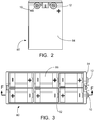
- the battery 80 has negative and positive terminals 10, 12 mounted on one of the end walls 84. This is somewhat different than typical batteries which have the terminals on a side wall 82.
- the terminals 10, 12 are used to connect the battery 12 to a busbar 76 using a bolt 70 (see FIGs. 17 and 18 ).
- FIG. 2 shows the end wall 84 of the battery 80 of FIG. 1 and the negative and positive terminals 10, 12.
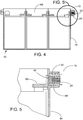
- FIG. 3 shows a top view of the battery 80 with a section designated as F-F taken through the mid-point of the negative terminal 10. This sectional view of the battery 80 is shown in FIG. 4 and it illustrates how the negative terminal 10 is connected to the negative battery plate and how the plates in the adjacent cells 86 are connected.
- the negative terminal 10 in FIG. 4 is shown in more detail in FIG. 5 .
- FIG. 5 is a detail view of the negative terminal 10 of the battery 80 and it shows a bushing 30 molded into the battery casing 88 and an insert 20 inside the bushing 30.
- a connector 90 inside the battery 80 connects the negative battery plate to the negative terminal 10.
- the region where the negative terminal 10 is welded to the connector 90 is known as the weld zone 92. If an overlong terminal bolt 70 (see FIGs. 17 and 18 ) is over-tightened, it can damage the weld zone and cause arcing.
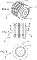
- FIG. 6 shows the bushing 30 with the insert 20 inside the open end 34.
- the closed end 32 of the bushing 30 is connected to the plate on the inside of the battery 80 via the connector 90 by the weld zone 92 (see FIG. 5 ).
- the outside of the bushing 30 is formed by a plurality of sections 36 that secure the bushing 30 in the molded battery casing 88.
- the present invention includes this design and other similar designs that are well known in the art.
- FIG. 7 is a side view of the bushing 30 and insert 20 shown in FIG. 6 with a section designated as A-A taken through the longitudinal axis. This sectional view is illustrated in FIG. 9 .
- FIG. 8 is an end view of the open end 34 of the bushing 30 and the insert 20 shown in FIG. 6 .
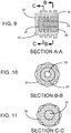
- FIG. 9 shows section A-A of the bushing 30 and the insert 20 from FIG. 7 .
- the sectional view shows how the insert 20 is formed in the bushing 30.
- the insert 20, which is typically made from brass, is machined into the desired shape and the bushing 30, which is typically made from lead, is molded around the insert 20.
- the closed end 22 of the insert 20 contacts the closed end 32 of the bushing 30.
- the opening 26 in the insert 20 receives a bolt 70 (see FIGs. 17 and 18 ) when the battery 80 is connected to a load.
- the bushing 30 and the insert 20 have two sections in FIG. 9 designated as B-B and C-C, which are transverse sections.
- Section B-B is a section taken at a point inside the open end 34 of the bushing 30
- section C-C is a section taken at the end of the opening 26 in the insert 20.
- FIG. 10 shows section B-B of the bushing 30 and the insert 20 in FIG. 9 near the open end 34 of the bushing 30.
- a threaded opening 26 in the center of the insert 20 is designed to receive a bolt 70 (see FIGs. 17 and 18 ).
- FIG. 11 shows section C-C of the bushing 30 and the insert 20 in FIG. 9 near the mid-section of the bushing 30 and at the end of the opening 26 (i.e., at the back wall) in the insert 20.
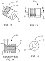
- FIG. 12 shows an embodiment of an insert 20 of the present invention.
- the insert 20 has a closed end 22 and a threaded open end 24 that is designed to receive a bolt 70 (see FIGs. 17 and 18 ).
- the insert 20 is cylindrically-shaped and the exterior wall has a plurality of radial members 28 extending outwardly which engage the interior wall of the bushing 30 ( FIG. 9 ).
- FIG. 13 is a side view of the insert 20 shown in FIG. 12 with a closed end 22, an open end 24 and a section designated as E-E taken through the longitudinal axis.
- FIG. 14 shows section E-E of the insert 20 in FIG. 13 with an opening 26 extending from the open end 24 to a back wall 25 which has a thickness "D" measured from the bottom of the opening 26 to the closed end 22.
- FIG. 15 shows the open end 24 of the insert 20 in FIG. 13 with the opening 26 along the longitudinal axis.
- FIG. 16 is a side view of an embodiment of a battery terminal 10 molded into a battery casing 88 with a threaded opening 26 in the insert 20 for receiving a bolt 70 ( FIGs. 17 and 18 ).
- the terminal 10 is connected via the connector 90 to the battery plate (not shown) by the weld zone 92 where the closed end 32 of the bushing 30 is welded to the connector 90 inside the battery.
- FIG. 17 is a side view and FIG. 18 is a side sectional view of an embodiment of the battery terminal 10 with a bolt 70 threaded into the insert 20.
- a lock washer 72 In between the bolt 70 and the insert 20 are a lock washer 72, a washer 74 and a copper busbar 76.
- the busbar 76 connects the battery 80 to a load.
- FIG. 19 shows a brass insert 120, a copper insert 120' and a stainless steel bolt 170 similar to the inserts and bolts used in the tests described below.
- FIG. 20 shows a coupling nut 260 and a stainless steel bolt 270 similar to the coupling nuts and stainless steel bolts that were used in the tests described below.
- Tests were conducted to predict the torque necessary to produce a failure mode for the insert back wall deformation, the insert thread strip and the bolt breakage. These three failure modes were determined to be the most likely result from applying an excessive torque to a correct length bolt or an overlong bolt at the battery connection.
- a calibrated digital torque wrench was used to measure the force applied to a bolt. Since actual torque values can vary based on the individual user, all torquing was performed by the same individual to minimize variations caused by the user.
- the inserts and bolts were obtained from commercial hardware suppliers. The factors and levels of the experiments are shown in Tables 1, 3 and 5.
- the inserts were machined out of 360 brass (also referred to as Alloy 360 or Brass 360an alloy mixture of copper and zinc with a small amount of lead) and C14500 copper (a phosphorus deoxidized, tellurium bearing copper alloy) roll stock.
- the bolts were made of 18-8 stainless steel.
- a black oxide alloy steel bolt was used to measure insert thread strength in order to obtain torque values above the break point of an 18-8 stainless steel bolt.
- Fixtures were fabricated to hold the inserts in place during testing.
- a calibrated digital gauge was affixed to the fixture and used to determine the level of back wall deformation. Coupling nuts were used in the tests for determining bolt strength.
- the tests for the back wall thickness determined that the type of material used to make the insert (e.g., brass or copper) was not statistically significant to the torque value required to cause a failure.
- the test results indicated that a back wall thickness of 0,483 cm (0.190 inch) would require a torque of greater than 21,91 Nm (193.9 in-Ib) to fail.
- Three inserts with a 0,483 cm (0.190 inch) back wall thickness were tested to verify the results.
- the bolts in the inserts were torqued to about 22,1 to 22,4 Nm (about 196 to 198 in-Ibs) and the average deformation was measured to be 0,028 cm (0.011 inch).
- the thread strength of the insert was measured by mounting the insert in a fixture held in a vise, placing hardened steel washers between the bolt and the insert to provide a known length of engagement (i.e., the length of the bolt extending into the insert) and driving the bolt into the insert until the threads of the insert stripped, while monitoring and recording the torque value.
- a black oxide alloy steel bolt was used in place of a stainless steel bolt for these tests because the stainless steel bolts broke before the threads failed.
- Five tests were performed for each type of insert, using new bolts and inserts for each test.
- the insert thread strength factors, levels and runs are shown in Table 3 and the summary of the insert thread test results are shown in Table 4.
- the unsupported bolt strength experiment included driving a first bolt fully into one end of a coupling nut (see FIG. 20 ) mounted in a vise, driving a second bolt fully into the opposing end of a coupling nut until contact was made with the first bolt near the mid-portion of the nut, continuing to drive the second bolt until the bolt broke, while monitoring and recording the torque value.
- Fifteen bolts were tested, using new bolts and coupling nuts for each test.
- the average torque value necessary to break a 1/4" x 20 18-8 stainless steel bolt with an unsupported head was 20,42 Nm (180.7 in-Ib).
- the supported bolt strength experiment included driving a bolt fully into one end of a coupling nut mounted in a vise until the bolt broke, while monitoring and recording the torque value. Eighteen bolts were tested, using new bolts and coupling nuts for each test. The average torque value necessary to break a 1/4" x 20 18-8 stainless steel bolt with a supported head was 22,90 Nm (202.7 in-Ib). Table 6 Bolt strength results summary Design Dimension DesignMaterial Design Torque to Failure, Mean Nm (in-Ib) Design Torque to Failure, Std.
- a 360 brass insert back wall thickness of 0,483 cm (0.190 inch) results in a 1/4" x 20 18-8 stainless overlong bolt head breaking prior to a back wall deflection of greater than 0,025 cm (0.010 inch).
- a 1/4" x 20 x 0.625" bolt with a supported head and a length of engagement of at least 0,986 cm (0.388 inch) will break prior to the insert threads stripping.
Landscapes
- Chemical & Material Sciences (AREA)
- Chemical Kinetics & Catalysis (AREA)
- Electrochemistry (AREA)
- General Chemical & Material Sciences (AREA)
- Connection Of Batteries Or Terminals (AREA)
Claims (5)
- Batterieanschluss (10) mit Gewinde, welcher einen Anschlussbolzen (70) aufnimmt, wobei der Batterieanschluss (10) umfasst:eine Buchse (30) mit einer axialen Bohrung, welche sich zwischen einem offenen Ende und einem geschlossenen Ende erstreckt; undeinen Einsatz (20) mit einer Längsachse und einer Öffnung (26) mit Gewinde, welche sich entlang der Längsachse erstreckt,wobei der Einsatz (20) in der Buchse (30) ausgebildet ist und die Öffnung (26) mit Gewinde ausgestaltet ist, um einen Bolzen aufzunehmen,dadurch gekennzeichnet, dass sich die Öffnung mit Gewinde des Einsatzes zwischen einem offenen Ende (24) und einer Rückwand erstreckt, wobei die Rückwand (25) eine minimale Dicke von 4,318 mm (0,170 Zoll) aufweist und sich um weniger oder gleich 0,254 mm (0,010 Zoll) verformt, wenn der Bolzen (70) ein überlanger Bolzen ist, welcher in die Öffnung (26) geschraubt wird und die Rückwand (25) mit einer Drehkraft von bis zu 21,91 Nm (193,9 Zoll-Pfund) kontaktiert, und wobei, wenn der Bolzen einen Gewindeeingriff von 0,597 cm (0,235 Zoll) oder mehr aufweist, der Bolzen (70) bricht, bevor das Einsatzgewinde durch eine fortgesetzte Drehung des Bolzens (70) beschädigt wird.
- Batterieanschluss mit Gewinde nach Anspruch 1, wobei der Einsatz (20) aus Messing oder Kupfer hergestellt ist, und wobei die Buchse (30) aus Blei hergestellt ist.
- Batterieanschluss mit Gewinde nach Anspruch 1 oder 2, wobei der Einsatz (20) durch einen Formgebungsprozess in der Buchse (30) ausgebildet ist.
- Batterieanschluss mit Gewinde nach Anspruch 1, wobei die Rückwand eine Dicke von 4,826 mm (0,190 Zoll) aufweist.
- Batterie, welche einen Batterieanschluss mit Gewinde nach einem der vorhergehenden Ansprüche und ein ausgebildetes Batteriegehäuse umfasst.
Applications Claiming Priority (1)
| Application Number | Priority Date | Filing Date | Title |
|---|---|---|---|
| US12/156,571 US8372537B2 (en) | 2008-06-03 | 2008-06-03 | Battery with a molded in-front terminal |
Publications (2)
| Publication Number | Publication Date |
|---|---|
| EP2146387A1 EP2146387A1 (de) | 2010-01-20 |
| EP2146387B1 true EP2146387B1 (de) | 2018-09-12 |
Family
ID=41380255
Family Applications (1)
| Application Number | Title | Priority Date | Filing Date |
|---|---|---|---|
| EP09161801.7A Active EP2146387B1 (de) | 2008-06-03 | 2009-06-03 | Eine Batterie mit einem geformten vorderen Anschluss |
Country Status (10)
| Country | Link |
|---|---|
| US (1) | US8372537B2 (de) |
| EP (1) | EP2146387B1 (de) |
| CN (1) | CN101609876B (de) |
| BR (1) | BRPI0904181B1 (de) |
| CA (1) | CA2667649C (de) |
| ES (1) | ES2705005T3 (de) |
| MX (1) | MX2009005819A (de) |
| PT (1) | PT2146387T (de) |
| SA (1) | SA109300355B1 (de) |
| TW (1) | TWI374567B (de) |
Families Citing this family (9)
| Publication number | Priority date | Publication date | Assignee | Title |
|---|---|---|---|---|
| US9099730B2 (en) * | 2010-01-21 | 2015-08-04 | C&D Technologies, Inc. | Storage battery having molded-in terminal |
| KR101392799B1 (ko) * | 2012-06-07 | 2014-05-14 | 주식회사 엘지화학 | 안정성이 향상된 구조 및 높은 냉각 효율성을 갖는 전지모듈 |
| US20140120383A1 (en) * | 2012-10-25 | 2014-05-01 | John Bradford Janik | Apparatus and method for high power density power discharge from a battery pack |
| WO2014141579A1 (ja) * | 2013-03-15 | 2014-09-18 | パナソニック株式会社 | 鉛蓄電池用ブッシングおよび鉛蓄電池 |
| CA2927501C (en) * | 2013-10-16 | 2017-06-20 | Aleees Eco Ark Co. Ltd. | Positive locking confirmation mechanism for battery contact of electric vehicle |
| US10056598B2 (en) * | 2014-08-26 | 2018-08-21 | Johnson Controls Technology Company | Recessed terminal in module body |
| USD782409S1 (en) | 2015-03-30 | 2017-03-28 | Johnson Controls Technology Company | Lithium ion battery cell with terminal washers |
| DE202022101159U1 (de) * | 2021-03-02 | 2022-04-11 | Hyundai Mobis Co., Ltd. | Batterie-Wasserdichtigkeitsstruktur |
| KR102821909B1 (ko) * | 2022-07-08 | 2025-06-18 | 주식회사 엘지에너지솔루션 | 배터리 팩 |
Citations (2)
| Publication number | Priority date | Publication date | Assignee | Title |
|---|---|---|---|---|
| US4729934A (en) * | 1986-11-25 | 1988-03-08 | Krystaszek Henry J | Battery side terminal |
| US5814421A (en) * | 1996-12-20 | 1998-09-29 | Tulip Corporation | Method and apparatus for making a battery terminal and a battery terminal made thereby |
Family Cites Families (29)
| Publication number | Priority date | Publication date | Assignee | Title |
|---|---|---|---|---|
| US3711335A (en) | 1971-02-12 | 1973-01-16 | Esb Inc | Battery having terminal molded in wall of container |
| BE792980A (fr) | 1971-12-20 | 1973-04-16 | Gould Inc | Ensemble polaire lateral pour batterie |
| GB1547089A (en) | 1977-03-02 | 1979-06-06 | Chloride Group Ltd | Battery terminals |
| US4166210A (en) | 1977-04-26 | 1979-08-28 | General Battery Corporation | Electrodes for use in the extrusion-fusion welding of lead parts through an aperture in a battery case |
| US4207390A (en) | 1978-11-02 | 1980-06-10 | Gould Inc. | One piece battery side terminal connector |
| US4446214A (en) | 1979-02-26 | 1984-05-01 | The Richardson Company | Method for forming a metal casting extending through a preformed structure and articles produced thereby |
| US4239841A (en) | 1979-12-10 | 1980-12-16 | Teledyne Industries, Inc. | Aircraft battery |
| US4304827A (en) | 1980-05-27 | 1981-12-08 | Exide Corporation | Side terminal battery |
| US4351890A (en) | 1980-07-31 | 1982-09-28 | General Battery Corporation | Battery case having a side terminal molded therein |
| US4396692A (en) | 1980-12-11 | 1983-08-02 | General Battery Corporation | Variable side terminal for use in a storage battery |
| US4337301A (en) | 1981-02-23 | 1982-06-29 | Teledyne Industries, Inc. | Aircraft battery |
| US4419815A (en) | 1981-02-23 | 1983-12-13 | Teledyne Industries, Inc. | Method of making an aircraft battery |
| US4472486A (en) | 1983-05-06 | 1984-09-18 | Concorde Battery Corporation | Terminal support member |
| US4455357A (en) | 1983-05-09 | 1984-06-19 | Teledyne Industries, Inc. | Housing assembly for aircraft batteries |
| US4482618A (en) | 1983-05-09 | 1984-11-13 | Concorde Battery Corporation | Aircraft battery |
| JPS618847A (ja) | 1984-06-25 | 1986-01-16 | Shin Kobe Electric Mach Co Ltd | 鉛蓄電池接続端子部の製造法 |
| US4883729A (en) | 1988-05-02 | 1989-11-28 | Gates Energy Product, Inc. | Battery terminal locking assembly |
| US5296317A (en) | 1992-09-03 | 1994-03-22 | Water Gremlin Co. | High torque battery terminal and method of making same |
| US5281493A (en) | 1992-09-04 | 1994-01-25 | Globe-Union Inc. | Terminal construction for a battery |
| JPH0668322U (ja) | 1993-03-09 | 1994-09-22 | 住友電装株式会社 | バッテリー・ターミナル |
| US5422202A (en) | 1993-06-17 | 1995-06-06 | Tulip Corporation | Side wall electrical battery terminal |
| US5791183A (en) | 1995-05-17 | 1998-08-11 | Tulip Corporation | Apparatus and method for cold forming a ring on a lead alloy battery terminal including an anti-torque structure |
| BR9706160A (pt) | 1996-10-09 | 1999-04-13 | Casais Osvaldo Balbino | Extremidade anti-corrosiva com fixação curta sem linhas de uni o para baterias |
| JP3428336B2 (ja) | 1996-12-26 | 2003-07-22 | 松下電器産業株式会社 | 角形密閉式蓄電池 |
| CA2274483C (en) | 1997-10-07 | 2006-01-31 | Matsushita Electric Industrial Co., Ltd. | Non-aqueous electrolyte secondary battery |
| US6372382B2 (en) | 1999-08-21 | 2002-04-16 | Gnb Technologies, Inc. | Low profile front terminal lead-acid battery |
| US6737192B2 (en) | 2001-02-21 | 2004-05-18 | The Furukawa Battery Co., Ltd. | Terminal structure of storage battery |
| BRPI0315125B1 (pt) * | 2002-10-07 | 2016-01-26 | Newfrey Llc | prendedor e construção de parafuso prisioneiro, método de acoplar uma haste rosqueada a uma estrutura e parafuso prisioneiro |
| US7163764B2 (en) | 2003-10-16 | 2007-01-16 | Water Gremlin Company | Enhanced torque resistant battery part |
-
2008
- 2008-06-03 US US12/156,571 patent/US8372537B2/en active Active
-
2009
- 2009-05-29 CA CA2667649A patent/CA2667649C/en active Active
- 2009-06-02 TW TW098118233A patent/TWI374567B/zh active
- 2009-06-02 BR BRPI0904181-8A patent/BRPI0904181B1/pt active IP Right Grant
- 2009-06-02 MX MX2009005819A patent/MX2009005819A/es active IP Right Grant
- 2009-06-03 EP EP09161801.7A patent/EP2146387B1/de active Active
- 2009-06-03 ES ES09161801T patent/ES2705005T3/es active Active
- 2009-06-03 SA SA109300355A patent/SA109300355B1/ar unknown
- 2009-06-03 PT PT09161801T patent/PT2146387T/pt unknown
- 2009-06-03 CN CN200910146596.5A patent/CN101609876B/zh active Active
Patent Citations (2)
| Publication number | Priority date | Publication date | Assignee | Title |
|---|---|---|---|---|
| US4729934A (en) * | 1986-11-25 | 1988-03-08 | Krystaszek Henry J | Battery side terminal |
| US5814421A (en) * | 1996-12-20 | 1998-09-29 | Tulip Corporation | Method and apparatus for making a battery terminal and a battery terminal made thereby |
Also Published As
| Publication number | Publication date |
|---|---|
| CN101609876B (zh) | 2014-12-24 |
| US20090297943A1 (en) | 2009-12-03 |
| BRPI0904181B1 (pt) | 2019-03-26 |
| CA2667649C (en) | 2013-01-22 |
| ES2705005T3 (es) | 2019-03-21 |
| CA2667649A1 (en) | 2009-12-03 |
| EP2146387A1 (de) | 2010-01-20 |
| BRPI0904181A2 (pt) | 2011-02-01 |
| US8372537B2 (en) | 2013-02-12 |
| TW201004014A (en) | 2010-01-16 |
| TWI374567B (en) | 2012-10-11 |
| CN101609876A (zh) | 2009-12-23 |
| MX2009005819A (es) | 2010-01-15 |
| PT2146387T (pt) | 2018-12-19 |
| SA109300355B1 (ar) | 2013-07-28 |
Similar Documents
| Publication | Publication Date | Title |
|---|---|---|
| CA2667649C (en) | A battery with a molded in-front terminal | |
| US20080274645A1 (en) | High power terminal block assembly | |
| CA2573750C (en) | Dual size stud electrical connector | |
| EP2333872B1 (de) | Batteriepack mit hoher Kapazität | |
| US10965043B2 (en) | Set screw connector | |
| US10483517B2 (en) | Bus bar assembly structure and battery module | |
| US4337301A (en) | Aircraft battery | |
| EP4383469B1 (de) | Ladedose und fahrzeug | |
| US4729934A (en) | Battery side terminal | |
| US4239841A (en) | Aircraft battery | |
| EP1544878A2 (de) | Verriegelbare Bevestiging für Schutzschalter. | |
| EP4372925A1 (de) | Endgerät mit speicherfunktion | |
| CN118554137A (zh) | 固定装置及安装方法 | |
| JP3518962B2 (ja) | リチウムイオン電池用アルミニウム電極柱 | |
| US7283370B2 (en) | Anti-strip screw boss | |
| CN210668702U (zh) | 一种大电流插孔 | |
| CN210640394U (zh) | 一种牵引变压器用电连接器 | |
| US4194806A (en) | Connector | |
| CN218031008U (zh) | 一种抗震防松螺栓组件 | |
| JP2007035520A (ja) | 車両用の電源装置 | |
| CN110838630B (zh) | 一种牵引变压器用电连接器 | |
| CN223450724U (zh) | 电气开关 | |
| CN222455227U (zh) | 用于核电厂凝汽器牺牲阳极组件 | |
| CN217768788U (zh) | 过电流连接器 | |
| JP2956529B2 (ja) | ネジ締め機構 |
Legal Events
| Date | Code | Title | Description |
|---|---|---|---|
| PUAI | Public reference made under article 153(3) epc to a published international application that has entered the european phase |
Free format text: ORIGINAL CODE: 0009012 |
|
| AK | Designated contracting states |
Kind code of ref document: A1 Designated state(s): AT BE BG CH CY CZ DE DK EE ES FI FR GB GR HR HU IE IS IT LI LT LU LV MC MK MT NL NO PL PT RO SE SI SK TR |
|
| 17P | Request for examination filed |
Effective date: 20100622 |
|
| STAA | Information on the status of an ep patent application or granted ep patent |
Free format text: STATUS: EXAMINATION IS IN PROGRESS |
|
| 17Q | First examination report despatched |
Effective date: 20161027 |
|
| RIC1 | Information provided on ipc code assigned before grant |
Ipc: H01M 2/30 20060101AFI20180329BHEP |
|
| GRAP | Despatch of communication of intention to grant a patent |
Free format text: ORIGINAL CODE: EPIDOSNIGR1 |
|
| STAA | Information on the status of an ep patent application or granted ep patent |
Free format text: STATUS: GRANT OF PATENT IS INTENDED |
|
| INTG | Intention to grant announced |
Effective date: 20180508 |
|
| GRAS | Grant fee paid |
Free format text: ORIGINAL CODE: EPIDOSNIGR3 |
|
| GRAA | (expected) grant |
Free format text: ORIGINAL CODE: 0009210 |
|
| STAA | Information on the status of an ep patent application or granted ep patent |
Free format text: STATUS: THE PATENT HAS BEEN GRANTED |
|
| AK | Designated contracting states |
Kind code of ref document: B1 Designated state(s): AT BE BG CH CY CZ DE DK EE ES FI FR GB GR HR HU IE IS IT LI LT LU LV MC MK MT NL NO PL PT RO SE SI SK TR |
|
| REG | Reference to a national code |
Ref country code: GB Ref legal event code: FG4D |
|
| REG | Reference to a national code |
Ref country code: CH Ref legal event code: EP |
|
| REG | Reference to a national code |
Ref country code: IE Ref legal event code: FG4D |
|
| REG | Reference to a national code |
Ref country code: DE Ref legal event code: R096 Ref document number: 602009054435 Country of ref document: DE |
|
| REG | Reference to a national code |
Ref country code: AT Ref legal event code: REF Ref document number: 1041631 Country of ref document: AT Kind code of ref document: T Effective date: 20181015 |
|
| REG | Reference to a national code |
Ref country code: PT Ref legal event code: SC4A Ref document number: 2146387 Country of ref document: PT Date of ref document: 20181219 Kind code of ref document: T Free format text: AVAILABILITY OF NATIONAL TRANSLATION Effective date: 20181211 |
|
| REG | Reference to a national code |
Ref country code: NL Ref legal event code: MP Effective date: 20180912 |
|
| REG | Reference to a national code |
Ref country code: LT Ref legal event code: MG4D |
|
| PG25 | Lapsed in a contracting state [announced via postgrant information from national office to epo] |
Ref country code: NO Free format text: LAPSE BECAUSE OF FAILURE TO SUBMIT A TRANSLATION OF THE DESCRIPTION OR TO PAY THE FEE WITHIN THE PRESCRIBED TIME-LIMIT Effective date: 20181212 Ref country code: SE Free format text: LAPSE BECAUSE OF FAILURE TO SUBMIT A TRANSLATION OF THE DESCRIPTION OR TO PAY THE FEE WITHIN THE PRESCRIBED TIME-LIMIT Effective date: 20180912 Ref country code: LT Free format text: LAPSE BECAUSE OF FAILURE TO SUBMIT A TRANSLATION OF THE DESCRIPTION OR TO PAY THE FEE WITHIN THE PRESCRIBED TIME-LIMIT Effective date: 20180912 Ref country code: FI Free format text: LAPSE BECAUSE OF FAILURE TO SUBMIT A TRANSLATION OF THE DESCRIPTION OR TO PAY THE FEE WITHIN THE PRESCRIBED TIME-LIMIT Effective date: 20180912 |
|
| PG25 | Lapsed in a contracting state [announced via postgrant information from national office to epo] |
Ref country code: LV Free format text: LAPSE BECAUSE OF FAILURE TO SUBMIT A TRANSLATION OF THE DESCRIPTION OR TO PAY THE FEE WITHIN THE PRESCRIBED TIME-LIMIT Effective date: 20180912 Ref country code: HR Free format text: LAPSE BECAUSE OF FAILURE TO SUBMIT A TRANSLATION OF THE DESCRIPTION OR TO PAY THE FEE WITHIN THE PRESCRIBED TIME-LIMIT Effective date: 20180912 |
|
| REG | Reference to a national code |
Ref country code: AT Ref legal event code: MK05 Ref document number: 1041631 Country of ref document: AT Kind code of ref document: T Effective date: 20180912 |
|
| REG | Reference to a national code |
Ref country code: ES Ref legal event code: FG2A Ref document number: 2705005 Country of ref document: ES Kind code of ref document: T3 Effective date: 20190321 |
|
| REG | Reference to a national code |
Ref country code: GR Ref legal event code: EP Ref document number: 20180403742 Country of ref document: GR Effective date: 20190422 |
|
| PG25 | Lapsed in a contracting state [announced via postgrant information from national office to epo] |
Ref country code: EE Free format text: LAPSE BECAUSE OF FAILURE TO SUBMIT A TRANSLATION OF THE DESCRIPTION OR TO PAY THE FEE WITHIN THE PRESCRIBED TIME-LIMIT Effective date: 20180912 Ref country code: AT Free format text: LAPSE BECAUSE OF FAILURE TO SUBMIT A TRANSLATION OF THE DESCRIPTION OR TO PAY THE FEE WITHIN THE PRESCRIBED TIME-LIMIT Effective date: 20180912 Ref country code: CZ Free format text: LAPSE BECAUSE OF FAILURE TO SUBMIT A TRANSLATION OF THE DESCRIPTION OR TO PAY THE FEE WITHIN THE PRESCRIBED TIME-LIMIT Effective date: 20180912 Ref country code: NL Free format text: LAPSE BECAUSE OF FAILURE TO SUBMIT A TRANSLATION OF THE DESCRIPTION OR TO PAY THE FEE WITHIN THE PRESCRIBED TIME-LIMIT Effective date: 20180912 Ref country code: RO Free format text: LAPSE BECAUSE OF FAILURE TO SUBMIT A TRANSLATION OF THE DESCRIPTION OR TO PAY THE FEE WITHIN THE PRESCRIBED TIME-LIMIT Effective date: 20180912 Ref country code: IS Free format text: LAPSE BECAUSE OF FAILURE TO SUBMIT A TRANSLATION OF THE DESCRIPTION OR TO PAY THE FEE WITHIN THE PRESCRIBED TIME-LIMIT Effective date: 20190112 Ref country code: PL Free format text: LAPSE BECAUSE OF FAILURE TO SUBMIT A TRANSLATION OF THE DESCRIPTION OR TO PAY THE FEE WITHIN THE PRESCRIBED TIME-LIMIT Effective date: 20180912 |
|
| PG25 | Lapsed in a contracting state [announced via postgrant information from national office to epo] |
Ref country code: SK Free format text: LAPSE BECAUSE OF FAILURE TO SUBMIT A TRANSLATION OF THE DESCRIPTION OR TO PAY THE FEE WITHIN THE PRESCRIBED TIME-LIMIT Effective date: 20180912 |
|
| REG | Reference to a national code |
Ref country code: DE Ref legal event code: R097 Ref document number: 602009054435 Country of ref document: DE |
|
| PLBE | No opposition filed within time limit |
Free format text: ORIGINAL CODE: 0009261 |
|
| STAA | Information on the status of an ep patent application or granted ep patent |
Free format text: STATUS: NO OPPOSITION FILED WITHIN TIME LIMIT |
|
| PG25 | Lapsed in a contracting state [announced via postgrant information from national office to epo] |
Ref country code: DK Free format text: LAPSE BECAUSE OF FAILURE TO SUBMIT A TRANSLATION OF THE DESCRIPTION OR TO PAY THE FEE WITHIN THE PRESCRIBED TIME-LIMIT Effective date: 20180912 |
|
| 26N | No opposition filed |
Effective date: 20190613 |
|
| PG25 | Lapsed in a contracting state [announced via postgrant information from national office to epo] |
Ref country code: SI Free format text: LAPSE BECAUSE OF FAILURE TO SUBMIT A TRANSLATION OF THE DESCRIPTION OR TO PAY THE FEE WITHIN THE PRESCRIBED TIME-LIMIT Effective date: 20180912 |
|
| PG25 | Lapsed in a contracting state [announced via postgrant information from national office to epo] |
Ref country code: MC Free format text: LAPSE BECAUSE OF FAILURE TO SUBMIT A TRANSLATION OF THE DESCRIPTION OR TO PAY THE FEE WITHIN THE PRESCRIBED TIME-LIMIT Effective date: 20180912 |
|
| REG | Reference to a national code |
Ref country code: CH Ref legal event code: PL |
|
| REG | Reference to a national code |
Ref country code: BE Ref legal event code: MM Effective date: 20190630 |
|
| PG25 | Lapsed in a contracting state [announced via postgrant information from national office to epo] |
Ref country code: TR Free format text: LAPSE BECAUSE OF FAILURE TO SUBMIT A TRANSLATION OF THE DESCRIPTION OR TO PAY THE FEE WITHIN THE PRESCRIBED TIME-LIMIT Effective date: 20180912 |
|
| PG25 | Lapsed in a contracting state [announced via postgrant information from national office to epo] |
Ref country code: IE Free format text: LAPSE BECAUSE OF NON-PAYMENT OF DUE FEES Effective date: 20190603 |
|
| PG25 | Lapsed in a contracting state [announced via postgrant information from national office to epo] |
Ref country code: CH Free format text: LAPSE BECAUSE OF NON-PAYMENT OF DUE FEES Effective date: 20190630 Ref country code: BE Free format text: LAPSE BECAUSE OF NON-PAYMENT OF DUE FEES Effective date: 20190630 Ref country code: LI Free format text: LAPSE BECAUSE OF NON-PAYMENT OF DUE FEES Effective date: 20190630 Ref country code: LU Free format text: LAPSE BECAUSE OF NON-PAYMENT OF DUE FEES Effective date: 20190603 |
|
| REG | Reference to a national code |
Ref country code: DE Ref legal event code: R079 Ref document number: 602009054435 Country of ref document: DE Free format text: PREVIOUS MAIN CLASS: H01M0002300000 Ipc: H01M0050543000 |
|
| PG25 | Lapsed in a contracting state [announced via postgrant information from national office to epo] |
Ref country code: CY Free format text: LAPSE BECAUSE OF FAILURE TO SUBMIT A TRANSLATION OF THE DESCRIPTION OR TO PAY THE FEE WITHIN THE PRESCRIBED TIME-LIMIT Effective date: 20180912 |
|
| PG25 | Lapsed in a contracting state [announced via postgrant information from national office to epo] |
Ref country code: HU Free format text: LAPSE BECAUSE OF FAILURE TO SUBMIT A TRANSLATION OF THE DESCRIPTION OR TO PAY THE FEE WITHIN THE PRESCRIBED TIME-LIMIT; INVALID AB INITIO Effective date: 20090603 Ref country code: MT Free format text: LAPSE BECAUSE OF FAILURE TO SUBMIT A TRANSLATION OF THE DESCRIPTION OR TO PAY THE FEE WITHIN THE PRESCRIBED TIME-LIMIT Effective date: 20180912 |
|
| PG25 | Lapsed in a contracting state [announced via postgrant information from national office to epo] |
Ref country code: MK Free format text: LAPSE BECAUSE OF FAILURE TO SUBMIT A TRANSLATION OF THE DESCRIPTION OR TO PAY THE FEE WITHIN THE PRESCRIBED TIME-LIMIT Effective date: 20180912 |
|
| PGFP | Annual fee paid to national office [announced via postgrant information from national office to epo] |
Ref country code: DE Payment date: 20250618 Year of fee payment: 17 |
|
| PGFP | Annual fee paid to national office [announced via postgrant information from national office to epo] |
Ref country code: GB Payment date: 20250620 Year of fee payment: 17 |
|
| PGFP | Annual fee paid to national office [announced via postgrant information from national office to epo] |
Ref country code: PT Payment date: 20250529 Year of fee payment: 17 |
|
| PGFP | Annual fee paid to national office [announced via postgrant information from national office to epo] |
Ref country code: FR Payment date: 20250618 Year of fee payment: 17 |
|
| PGFP | Annual fee paid to national office [announced via postgrant information from national office to epo] |
Ref country code: GR Payment date: 20250616 Year of fee payment: 17 Ref country code: BG Payment date: 20250613 Year of fee payment: 17 |
|
| PGFP | Annual fee paid to national office [announced via postgrant information from national office to epo] |
Ref country code: ES Payment date: 20250718 Year of fee payment: 17 |
|
| PGFP | Annual fee paid to national office [announced via postgrant information from national office to epo] |
Ref country code: IT Payment date: 20250630 Year of fee payment: 17 |