EP2146232B1 - Connector for an optical connection - Google Patents
Connector for an optical connection Download PDFInfo
- Publication number
- EP2146232B1 EP2146232B1 EP09008787.5A EP09008787A EP2146232B1 EP 2146232 B1 EP2146232 B1 EP 2146232B1 EP 09008787 A EP09008787 A EP 09008787A EP 2146232 B1 EP2146232 B1 EP 2146232B1
- Authority
- EP
- European Patent Office
- Prior art keywords
- plug
- displacement
- housing
- flap
- displacement part
- Prior art date
- Legal status (The legal status is an assumption and is not a legal conclusion. Google has not performed a legal analysis and makes no representation as to the accuracy of the status listed.)
- Active
Links
- 230000003287 optical effect Effects 0.000 title claims description 5
- 238000006073 displacement reaction Methods 0.000 claims description 76
- 238000007789 sealing Methods 0.000 claims description 13
- 239000013307 optical fiber Substances 0.000 description 11
- 239000000835 fiber Substances 0.000 description 4
- 230000002349 favourable effect Effects 0.000 description 3
- 238000005096 rolling process Methods 0.000 description 3
- 239000004020 conductor Substances 0.000 description 2
- 230000006978 adaptation Effects 0.000 description 1
- 230000006835 compression Effects 0.000 description 1
- 238000007906 compression Methods 0.000 description 1
- 238000010276 construction Methods 0.000 description 1
- 230000000694 effects Effects 0.000 description 1
- 230000008030 elimination Effects 0.000 description 1
- 238000003379 elimination reaction Methods 0.000 description 1
- 238000003780 insertion Methods 0.000 description 1
- 230000037431 insertion Effects 0.000 description 1
- 230000035515 penetration Effects 0.000 description 1
Images


Classifications
-
- G—PHYSICS
- G02—OPTICS
- G02B—OPTICAL ELEMENTS, SYSTEMS OR APPARATUS
- G02B6/00—Light guides; Structural details of arrangements comprising light guides and other optical elements, e.g. couplings
- G02B6/24—Coupling light guides
- G02B6/36—Mechanical coupling means
- G02B6/38—Mechanical coupling means having fibre to fibre mating means
- G02B6/3807—Dismountable connectors, i.e. comprising plugs
- G02B6/3833—Details of mounting fibres in ferrules; Assembly methods; Manufacture
- G02B6/3847—Details of mounting fibres in ferrules; Assembly methods; Manufacture with means preventing fibre end damage, e.g. recessed fibre surfaces
- G02B6/3849—Details of mounting fibres in ferrules; Assembly methods; Manufacture with means preventing fibre end damage, e.g. recessed fibre surfaces using mechanical protective elements, e.g. caps, hoods, sealing membranes
-
- G—PHYSICS
- G02—OPTICS
- G02B—OPTICAL ELEMENTS, SYSTEMS OR APPARATUS
- G02B6/00—Light guides; Structural details of arrangements comprising light guides and other optical elements, e.g. couplings
- G02B6/24—Coupling light guides
- G02B6/42—Coupling light guides with opto-electronic elements
- G02B6/4296—Coupling light guides with opto-electronic elements coupling with sources of high radiant energy, e.g. high power lasers, high temperature light sources
- G02B2006/4297—Coupling light guides with opto-electronic elements coupling with sources of high radiant energy, e.g. high power lasers, high temperature light sources having protection means, e.g. protecting humans against accidental exposure to harmful laser radiation
-
- G—PHYSICS
- G02—OPTICS
- G02B—OPTICAL ELEMENTS, SYSTEMS OR APPARATUS
- G02B6/00—Light guides; Structural details of arrangements comprising light guides and other optical elements, e.g. couplings
- G02B6/24—Coupling light guides
- G02B6/36—Mechanical coupling means
- G02B6/38—Mechanical coupling means having fibre to fibre mating means
- G02B6/3807—Dismountable connectors, i.e. comprising plugs
- G02B6/3873—Connectors using guide surfaces for aligning ferrule ends, e.g. tubes, sleeves, V-grooves, rods, pins, balls
- G02B6/3874—Connectors using guide surfaces for aligning ferrule ends, e.g. tubes, sleeves, V-grooves, rods, pins, balls using tubes, sleeves to align ferrules
- G02B6/3878—Connectors using guide surfaces for aligning ferrule ends, e.g. tubes, sleeves, V-grooves, rods, pins, balls using tubes, sleeves to align ferrules comprising a plurality of ferrules, branching and break-out means
- G02B6/3879—Linking of individual connector plugs to an overconnector, e.g. using clamps, clips, common housings comprising several individual connector plugs
Definitions
- the present invention relates to a plug part according to the preamble of patent claim 1.
- the connector parts may have one or more optical fibers, wherein these optical fibers of the connector are connected by nesting the connector parts together.
- closure flaps which are pivoted by displacing the displacement parts, these closure caps closing receiving channels for the ferrules covering the light guides.
- this has the disadvantage that a separate closure flap must be provided for each receiving channel, which can be very costly in the case of plug parts with a plurality of light guides.
- such connector parts have the disadvantage that not the entire interior in the housing but only the receiving channels for the ferrules are covered and thus protected.
- the object of the invention is to improve the generic plug parts to the effect.
- Sealing ring e.g. shifts by rolling in the guide space in the respective displacement direction, in which the sliding part is being moved. As a result, the friction forces occurring on the sealing ring are reduced. In addition, the wear is minimized, so that a permanent and secure seal is guaranteed.
- the closure flap is to be attached to the plug part such that it not only closes off individual receiving channels for light guides, as is known in the prior art, but the passage opening in the displacement part itself. As a result, the entire space behind it is protected. Conveniently, a seal is provided between the sliding part and closure flap, which seals the closure flap in its closed position against the sliding part. In this case, both a dust-proof and moisture-proof finish can be achieved.
- the word "closed” also encompasses the cases in which the closure flap only covers the passage opening when it is more a matter of purely mechanical protection of the light guides or of the other components within the housing. Also the term of the plug-in connection is very general.
- the term "inside the housing” is understood in particular to mean that the respective component is located at least partially in an interior encased by the housing.
- the displaceable relative to the housing displacement member may be arranged in this sense on the housing or in particular within the housing. But it does not necessarily have to be stored directly on the housing. This storage can also be done by interposing other components.
- the displacement part has an end face which is preferably arranged at least in the closed position of the closure flap, on an outside of the displacement part facing away from the light guide, and the passage opening an opening in the face is.
- the end face is conveniently the surface to which, for displacement of the sliding part, e.g. a force is exerted by a second end face of a sliding part of another plug part.
- the end face is thus conveniently the part of the sliding part which is acted upon in normal use with force to move the sliding part.
- Connector parts according to the invention can be used in particular for simultaneously connecting a plurality of light conductors of each plug part to one another by a single plug-in operation.
- at least two, preferably at least three or at least four, optical fibers are arranged within the housing of each plug part.
- the light guides are preferably held together, in a light guide carrier, which is preferably arranged relative to the housing immovably within the housing.
- the passage opening in the displacement part is conveniently made so large that the, preferably all, disposed within the housing of the connector part light guide together, preferably arranged within the housing of the connector part light conductor carrier, or, preferably all, light guide of another Plug parts of the connector together and / or a fiber optic carrier of another plug part of the connector in at least one position of the sliding part, in which the closure flap, the passage opening, preferably completely, releases, are passed through the passage opening (is).
- the plug part has at least one return spring for the sliding part, against the force of which the sliding part from its position in which the flap closes the passage opening in the direction towards the or the optical fibers is displaceable.
- the return spring is favorably supported on the housing or on a light guide carrier in the housing.
- a flap return spring is preferably provided. This acts on the flap in the direction of its closed position, so that the flap is returned by the flap return spring back into its closed position, preferably when or when it comes to relieving the displacement of, acting on the outside of these forces.
- the return spring for the sliding member and the flap return spring for the flap may be a single spring.
- each two separate springs are each two separate springs.
- more than two springs are possible, if this makes sense in a specific embodiment.
- the flap return spring serves as a pivot bearing for the flap or forms this pivot bearing.
- Generic connectors or connector parts often have at least partially a rounded in cross-section, in particular cylinder jacket-shaped, inner and / or outer contours.
- the closure flap has at least sections a curved outer contour, preferably in the form of a tube jacket section or a cylinder jacket section or a spherical surface. In this way, the closure flap can be made so large that it can close a relatively large passage opening, without consuming excessive space in the interior of the housing.
- the term of the pipe jacket section is curved regions which do not necessarily have to be bent in a circular manner, as is the case with cylinder jacket sections. Other deviations from the circular shape may also be provided in the cross section of the pipe jacket sections.
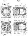
- the plug part 1 is a socket connector part or plug receiving part which is provided for mounting in a through hole in a wall.
- it has a mounting flange 27 arranged on the housing 5, as is known per se in the prior art.
- the sleeve plug part or plug receiving part is in this case the plug part, in which or in the housing of which the female light guides or receiving sleeves for the male light guides are arranged.
- Fig. 1 and 3 show views of this plug part 1, from the direction from which the corresponding male plug part or the plug is inserted.
- Fig. 1 shows the position in which the flap 4, the passage opening 7 completely closes.
- Fig. 2 shows the longitudinal section in this position according to the section line AA.
- Fig. 3 shows a top view like Fig. 1 However, here is the flap 4 folded back, so that the passage opening 7 completely open and the four arranged in this plug part light guide 3 can be seen.
- the attachment and storage of the light guide 3 in the optical fiber carrier 10 is carried out as known per se.
- ferrules which receive the optical fibers 3 are usually arranged at their ends.
- the ferrules can be arranged movably or fixedly in the optical waveguide 10.
- the ferrules and the optical fiber carrier can be designed as known per se as in the prior art.
- Fig. 4 shows a longitudinal section analogous to Fig. 2 however, by the in Fig. 3 shown opening position along the section line AA.
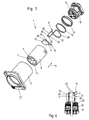
- Fig. 5 shows the individual components of this connector part 1 in an exploded view.
- Fig. 6 To illustrate the operation of the flip-reset spring 17 of this embodiment, the flap return spring 17 supported and mounted on the optical fiber carrier 10 in this embodiment is shown in which the left half of this illustration shows the flap 4 in the fully open position and the right part of FIG Fig. 6 the shutter 4 shows in its closed position. The remaining components of this connector part 1 are omitted in this illustration for the sake of clarity.
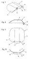
- the Fig. 7 to 10 show still different views of the flap 4 of this embodiment.
- the displacement part 6 is linearly displaceable in this embodiment, mounted along the direction of displacement 13 within the housing 5.
- the sliding directions 13 are conveniently parallel to the longitudinal central axis 21 of the plug part 1 and the housing 5.
- the sliding part 6 is slidably mounted in the concrete embodiment of the plug part 1 on the light guide carrier 10.
- the sealing ring 12 is provided. This is arranged in a direction parallel to the direction of displacement 13 of the sliding part 6 elongated, here annular jacket-shaped guide space 14. Due to the longitudinal extent of this guide space 14, it is possible that the sealing ring 12 shifts, for example, by rolling in the guide space 14 in the respective displacement direction 13, in which the displacement member 6 is moved relative to the light guide carrier 10. By this particular rolling displacement of the sealing ring 12, the frictional forces are primarily reduced.
- sealing ring not only on the concrete in Fig. 2 and 4 particularly good to see place or function can be used. Rather, it is also possible that this sealing ring is arranged between the displacement part 6 and the housing 5, or between the displacement part 6 and another preferably housing-fixed component of the plug part or acts.
- fixed to the housing is generally understood that between the housing-fixed component and the housing no relative movement takes place or can take place.
- the return spring 11 is provided to return the sliding part 6 of the in Fig. 4 shown position in, in Fig. 2 shown position corresponding to the closed position of the flap 4, the return spring 11 is provided.
- This is supported in the concretely shown embodiment of the plug part 1 on the light guide carrier 10, and carries on its opposite side the end face 9 away from the end of the sliding part 6 and is biased in such a way that the sliding part 6 in the in Fig. 2 shown position is pressed.
- this is a coil spring.
- other elastic bodies can be used.
- a support of the return spring 11 on the fiber optic carrier 10 is not absolutely necessary. Rather, a support can also be carried out directly on the housing 5 or on a preferably fixed to the housing connected component. The introduction of force to move the sliding part in the in Fig.
- the actuating element 8 arranged on the displacement part in this exemplary embodiment presses on the in Fig. 4 Dashed lines shown outer contour of the shutter 4, whereby the shutter from the in Fig. 2 shown closed position in the in Fig. 4 shown, fully open position is pivoted.
- the pivot axis 22, by which the closure flap 4 is pivoted, is in this embodiment a part of the flap return spring 17, which is particularly well in the exploded view according to FIG Fig. 5 you can see.
- this flap return spring 17 has two spring legs 23. These are biased towards each other, and act or press in this embodiment, two oppositely disposed inclined surfaces 24 which are provided on the closure flap 4. These inclined surfaces are arranged obliquely or in an angle deviating from 0 ° and 180 ° relative to the spring legs.
- the inclined surfaces 24 are arranged in the embodiment shown on a partially tubular axle guide 25 of the closure flap 4, wherein the pivot axis 22 about which the closure flap 4 is pivotable, is rotatably mounted in this axle guide 25.
- This storage is especially good in Fig. 6 to see.
- the storage and design of the inclined surfaces 24 goes particularly well from the FIGS. 7, 9 and 10 out.
- the pivot axis 22 is formed in the embodiment shown by two, compared to the remaining spring legs 23 angled and here facing each other extensions 26 of the respective spring leg 23. Between the two extensions 26, a gap is provided so that the spring legs 23 can be pressed apart from the inclined surfaces 24.
- the two spring legs 23 of the flap return spring 17 are integrally formed in the illustrated embodiment on a base sheet 28, which serves on the one hand for supporting and securing the flap return spring 17 - here at the light guide 10 and on the other hand can also contribute to the bias or spring action of the spring leg 23.
- any other attachment of the spring leg 23 to the fiber optic support 10 or to other components which are connected to the housing 5 or on the housing 5 itself conceivable.
- it does not necessarily have to be two in the direction of spring leg 23 biased towards each other. With correspondingly arranged inclined surfaces 24 on the closure flap 4, these spring legs 23 can also be biased in a direction pointing away from each other.
- pivot axis 22 is at least partially formed by at least one, preferably angled relative to the spring leg 23, extension 26 of the spring leg.
- This male plug part or plug-in part 2 is that plug part, on or in which or in the housing, the male or protruding light guide 3 are arranged, which are inserted into the female receptacles of the light guide of the socket 1.
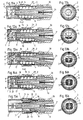
- the Fig. 11a to 15a show longitudinal sections through this plug part 2, wherein in Fig. 11a the closed position of the flap 4 and in Fig. 15a the completely open position of the closure flap 4 or the completely pushed back position of the displacement part 6 is shown. The position according to Fig.
- FIG. 15a is achieved when the male connector part 2 is fully inserted into the socket connector part 1.
- the Fig. 12a to 14a show different intermediate positions.
- the Fig. 11b to 15b show the respective views on the front side 9 of the connector part 2, wherein particularly particularly well the opening degree and the position of the closure flap in the position shown in each case can be seen.
- Fig. 16 again shows an exploded view of this connector part 2
- the Fig. 17 to 20 show different, each indicated in the individual figures sections through an arrangement of displacement part 6, additional sliding part 18 and shutter 4 of the connector part 2.
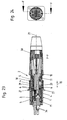
- Die FIGS. 21 and 22 show the flap 4 of this connector part 2 itself. Even if the individual components of the plug part 2 are formed differently than the corresponding components of the previously described connector part 1, so were the same designations and the same reference numerals are still selected for the components that each have the same function.
- a first significant difference forms the on the housing - here inside the housing 5 - relative to the housing 5 linearly displaceably mounted additional sliding part 18 which is linearly displaceable relative to the displacement part 6.
- additional sliding part 18 which is linearly displaceable relative to the displacement part 6.
- the valve return spring 17 acts, which is designed in this connector part 2 as a helical spring. Again, of course, any differently shaped and suitable elastic element can be used. From the flap return spring 17, the displacement part 6 is loaded or biased in the direction away from the additional displacement part 18. By this bias the flap return spring acts 17 also on the flap 4, as will be explained below.
- the closure flap 4 is rotatably mounted in this plug part 2 on the sliding part 6 and here likewise linearly displaceable in an additional guide groove 20 on or in the additional sliding part 18.
- a pair of axle pins 32 arranged opposite the closure flap legs 33 or on the closure flap 4 are predetermined, through which the pivot axis 22 runs.
- the axle journals 32 engage with this plug part 2 in each case in the axle journal receptacles 34 in the arms 35 of the sliding part 6. This is especially good in Fig. 19 to see.
- the axle journals 32 and the axle journal receptacle 34 also ensure that the closure flap 4 is displaced in a linear manner together with the displacement part 6 - in the case of the plug part 2 shown.
- an actuating element 8 is likewise provided in the case of this plug part 2. This is in the concrete example by the particularly good in the Fig. 16 and 17 to 19 such as 21 and 22 achieved to see peg-shaped actuators 8. In the concrete example, these are two pins arranged on the opposite closure flap legs 33 or pointing outwards. Of course, a pin would be sufficient as an actuator 8.
- the actuators 8 of this example are slidably mounted in Vietnamese cabinet, but this does not necessarily have to be so.
- the guide groove 19 along which the displacement part 6 can be displaced against the additional displacement part 18 is arranged orthogonally to the additional guide groove 8 in the case of the specifically shown plug part 2. But this does not necessarily have to be this way. It is also another, angular, that is not parallel arrangement of these two guide grooves 19 and 20 possible.
- Figs. 14a and 15a takes place at a corresponding load on the end face 9 but not only a relative displacement between the sliding part 6 and additional sliding part 18. These two components are rather pushed together into the housing interior. This is done under compression of the return spring 11, even with this plug part 2, this is supported on the fiber optic carrier 10, but what, as already explained above with respect to the connector part 1, not the only possible embodiment.
- the light guides 3 and a part of the light guide carrier 10 pass through the already opened through opening 7, which, as explained below, serves to connect the light guides 3 of the plug part 2 to the light guides 3 arranged in the plug part 1.
- the flap return spring 17 provides for the remaining provision in the in Fig. 11a shown closed position of the closure flap 4 in which the displacement part 6 from the additional sliding part 18 in the direction of displacement 13 and the here also parallel thereto direction of the longitudinal central axis 21 is spaced.
- the flap return spring 17 is advantageously softer or deformed with lower forces than the return spring 11. This is preferably true in general and in particular Plug part 1.
- the closure flap 4 for the reasons already mentioned on rounded areas. In the case of the plug part 2 shown, these are ball surface sections 16. Thus, the closure flap 4 in the closed position according to FIG Fig. 11a and Fig. 20 does not protrude beyond the sliding part 6, it has centrally a flattened area 31st
- the concrete plug part 2 predetermined by the axle 32 pivot axis 22 of the flap 4, in particular in the closed position of the flap 4, but here in all other positions relatively close to the longitudinal center axis 21. It also forms the center of the spherical surface sections 16, which leads to a space-optimized pivoting of the flap 4.
- the distance between the longitudinal central axis 21 of the housing 5 and the sliding part 6 and the pivot axis 22 about which the closure flap 4 is pivotable less than 10%, preferably less than 5%, of the maximum outer diameter of the sliding part ,
- the longitudinal central axis 21 and in most cases also the pivoting axis 22 are not actually physically present, continuous axes.
- the distance is the smallest distance between the longitudinal central axis 21 and pivot axis 22.
- the pivot axis 22 about which the closure flap 4 is pivotable, eccentric with respect to a longitudinal central axis 21 of the housing 5 and des Displacement parts 6 is arranged.
- Eccentric means that the pivot axis 22 does not intersect the longitudinal center axis 21, but is just arranged with a, although preferably small distance to this.
- housing end 30, which can be screwed in the connector part 2 shown on the housing 5. This is favorable in terms of a simple assembly of the plug part 2, but also not mandatory.
- the housing 5 may also have an integrally formed finish.
- a known per se locking sleeve 29 is provided on the plug part 2 also. This serves to lock the plug part 2 with the plug part 1 when they are completely pushed into each other and connected to prevent accidental release of this connection.
- the locking sleeve 29 and its latching on the plug part 1 can be carried out as known in the prior art, so that further explanations on this unnecessary.
- Fig. 23 now shows a partially sectioned view of the fully interconnected connector parts 1 and 2, in this position, the respective optical fiber 3 of the two connector parts are connected to each other so that light signals can be transmitted.
- Fig. 24 shows the section line FF the Fig. 23 , In the illustrated, contacted position, the two end faces 9 of the respective displacement parts 6 abut each other. The respective closing flaps 4 are fully opened, the sliding parts 6 are each inserted maximally into the respective housing 5, the light guide carrier 10 of the male plug part 2, together with its light guide, has penetrated the through openings 7 in both displacement parts 6, so that the light guides 3 of these two plug parts 1 and 2 vis-à-vis have been brought into contact with each other, as is well known.
- the light guide 3 of the connector part 1 can also be arranged fixed in this.
- the locking sleeve 29 To remove the plug part 2 from the plug part 1, the locking sleeve 29 must be operated accordingly, so that the predetermined connection between them is solved between the two plug parts, then the plug part 2 can be pulled out of the plug part 1, whereby the sliding parts 6 and the respective flaps 4 of the respective flap return springs 17 and the return springs 11 back in their closed positions in accordance with Fig. 11a and Fig. 1 and 2 be reset.
- the plug part 2 in the plug part 1 first meet the two end faces 9 of the sliding parts 6 to each other, causing them to move back and the shutter 4 are opened automatically, which by further insertion of the plug part 2 in the plug part 1 again in Fig. 23 shown connection position is achieved.
Description
Die vorliegende Erfindung betrifft ein Steckerteil gemäß des Oberbegriffs des Patentanspruchs 1.The present invention relates to a plug part according to the preamble of
Zur oben genannten Art ähnliche Steckerteile sind z.B. aus der
In den gattungsgemäßen Schriften
Bei diesen gattungsgemäßen Steckerteilen sind verschiedene Teile des Steckerteils gegeneinander verschiebbar. Um ein Eindringen von Verschmutzungen auch zwischen den relativ zueinander verschiebbaren Teilen des Steckerteils dauerhaft zu gewährleisten, benötigt man eine Art von Dichtung, welche mit möglichst geringem bzw. gar keinem Verschleiß das Verschieben von Teilen relativ zueinander innerhalb des Steckerteils erlaubt und trotzdem dauerhaft abdichtet.In these generic plug parts different parts of the plug part are mutually displaceable. In order to permanently ensure the penetration of dirt between the relatively displaceable parts of the plug part, one needs a kind of seal which allows with as little or no wear, the shifting of parts relative to each other within the plug part and still seals permanently.
Aufgabe der Erfindung ist es, gattungsgemäße Steckerteile dahingehend zu verbessern.The object of the invention is to improve the generic plug parts to the effect.
Erfindungsgemäß wird dies mit einem Steckerteil gemäß Patentanspruch 1 erreicht.This is achieved according to the invention with a plug part according to
Durch die genannte Längserstreckung des Führungsraums ist es möglich, dass sich derDue to the aforementioned longitudinal extension of the guide space, it is possible that the
Dichtungsring z.B. durch Abrollen im Führungsraum in die jeweilige Verschieberichtung verschiebt, in welche das Verschiebeteil gerade verschoben wird. Hierdurch werden die am Dichtungsring auftretenden Reibungskräfte reduziert. Zusätzlich wird auch die Abnutzung minimiert, sodass eine dauerhafte und sichere Abdichtung gewährleistet ist.Sealing ring e.g. shifts by rolling in the guide space in the respective displacement direction, in which the sliding part is being moved. As a result, the friction forces occurring on the sealing ring are reduced. In addition, the wear is minimized, so that a permanent and secure seal is guaranteed.
Die Verschlussklappe ist so am Steckerteil anzubringen, dass diese nicht nur, wie beim Stand der Technik bekannt, einzelne Aufnahmekanäle für Lichtleiter, sondern die Durchtrittsöffnung im Verschiebeteil an sich verschließt. Hierdurch ist der gesamte dahinterliegende Raum geschützt. Günstigerweise ist zwischen Verschiebeteil und Verschlussklappe dabei eine Dichtung vorgesehen, die die Verschlussklappe in ihrer Schließstellung gegen das Verschiebeteil abdichtet. Dabei kann sowohl ein staub- als auch feuchtigkeitsdichter Abschluss erreicht werden. Das Wort "verschlossen" umfasst aber auch die Fälle, in denen die Verschlussklappe die Durchtrittsöffnung lediglich abdeckt, wenn es mehr um einen rein mechanischen Schutz der Lichtleiter bzw. der anderen Bauteile innerhalb des Gehäuses geht. Auch der Begriff der Steckverbindung ist sehr allgemein aufzufassen. Es geht hierbei zunächst einmal um ein, vorzugsweise lineares, Zusammenführen von zwei Steckerteilen, wobei gegebenenfalls aber auch zusätzlich Schraub-, Dreh- oder sonstige Bewegungen zum Verbinden der Steckerteile notwendig bzw. vorgesehen sein können. Unter der Bezeichnung "innerhalb des Gehäuses" wird insbesondere verstanden, dass sich der jeweilige Bauteil zumindest zum Teil in einem vom Gehäuse ummantelten Innenraum befindet. Das relativ zum Gehäuse verschiebbare Verschiebeteil kann in diesem Sinne an dem Gehäuse oder insbesondere innerhalb des Gehäuses angeordnet sein. Es muss aber nicht zwingend direkt am Gehäuse gelagert sein. Diese Lagerung kann auch durch Zwischenschaltung von anderen Bauteilen erfolgen.The closure flap is to be attached to the plug part such that it not only closes off individual receiving channels for light guides, as is known in the prior art, but the passage opening in the displacement part itself. As a result, the entire space behind it is protected. Conveniently, a seal is provided between the sliding part and closure flap, which seals the closure flap in its closed position against the sliding part. In this case, both a dust-proof and moisture-proof finish can be achieved. However, the word "closed" also encompasses the cases in which the closure flap only covers the passage opening when it is more a matter of purely mechanical protection of the light guides or of the other components within the housing. Also the term of the plug-in connection is very general. This is initially about a, preferably linear, merging of two connector parts, but optionally also additional screw, rotary or other movements for connecting the connector parts may be necessary or provided. The term "inside the housing" is understood in particular to mean that the respective component is located at least partially in an interior encased by the housing. The displaceable relative to the housing displacement member may be arranged in this sense on the housing or in particular within the housing. But it does not necessarily have to be stored directly on the housing. This storage can also be done by interposing other components.
Um mit der Verschlussklappe einen möglichst großen Teil des Innenraums im Gehäuse abschirmen zu können, ist günstigerweise vorgesehen, dass das Verschiebeteil eine Stirnfläche aufweist, welche vorzugsweise zumindest in der Schließstellung der Verschlussklappe, auf einer vom Lichtleiter abgewandten Außenseite des Verschiebeteils angeordnet ist, und die Durchtrittsöffnung eine Öffnung in der Stirnfläche ist. Dies ermöglicht es, den Steckerteil mittels der Verschlusskappe möglichst weit vorne verschließen zu können. Die Stirnfläche ist günstigerweise die Fläche, auf die zum Verschieben des Verschiebeteils z.B. durch eine zweite Stirnfläche eines Verschiebeteils eines anderen Steckerteils eine Kraft ausgeübt wird. Die Stirnfläche ist somit günstigerweise der Teil des Verschiebeteils, der im normalen Gebrauch mit Kraft beaufschlagt wird, um das Verschiebeteil zu verschieben.In order to be able to shield as much of the interior as possible in the housing with the closure flap, it is expediently provided that the displacement part has an end face which is preferably arranged at least in the closed position of the closure flap, on an outside of the displacement part facing away from the light guide, and the passage opening an opening in the face is. This makes it possible to close the plug part as far as possible by means of the cap. The end face is conveniently the surface to which, for displacement of the sliding part, e.g. a force is exerted by a second end face of a sliding part of another plug part. The end face is thus conveniently the part of the sliding part which is acted upon in normal use with force to move the sliding part.
Erfindungsgemäße Steckerteile können insbesondere dafür eingesetzt werden, gleichzeitig mehrere Lichtleiter eines jeden Steckerteils durch einen einzigen Steckvorgang miteinander zu verbinden. In diesem Sinne ist günstigerweise vorgesehen, dass innerhalb des Gehäuses eines jeden Steckerteils zumindest zwei, vorzugsweise zumindest drei oder zumindest vier, Lichtleiter angeordnet sind. Dabei kann vorgesehen sein, dass die Lichtleiter, vorzugsweise gemeinsam, in einem Lichtleiterträger gehalten sind, welcher, vorzugsweise relativ zum Gehäuse unverschiebbar, innerhalb des Gehäuses angeordnet ist.Connector parts according to the invention can be used in particular for simultaneously connecting a plurality of light conductors of each plug part to one another by a single plug-in operation. In this sense, it is advantageously provided that at least two, preferably at least three or at least four, optical fibers are arranged within the housing of each plug part. It can be provided that the light guides, are preferably held together, in a light guide carrier, which is preferably arranged relative to the housing immovably within the housing.
Die Durchtrittsöffnung im Verschiebeteil, vorzugsweise in dessen Stirnfläche, ist günstigerweise so groß ausgeführt, dass die, vorzugsweise alle, innerhalb des Gehäuses des Steckerteils angeordneten Lichtleiter gemeinsam, vorzugsweise der innerhalb des Gehäuses des Steckerteils angeordnete Lichtleiterträger, oder die, vorzugsweise alle, Lichtleiter eines anderen Steckerteils der Steckverbindung gemeinsam und/oder ein Lichtleiterträger eines anderen Steckerteils der Steckverbindung in zumindest einer Stellung des Verschiebeteils, in der die Verschlussklappe die Durchtrittsöffnung, vorzugsweise vollständig, freigibt, durch die Durchtrittsöffnung hindurchgeführt sind (ist).The passage opening in the displacement part, preferably in its end face, is conveniently made so large that the, preferably all, disposed within the housing of the connector part light guide together, preferably arranged within the housing of the connector part light conductor carrier, or, preferably all, light guide of another Plug parts of the connector together and / or a fiber optic carrier of another plug part of the connector in at least one position of the sliding part, in which the closure flap, the passage opening, preferably completely, releases, are passed through the passage opening (is).
Im Sinne einer automatischen Rückstellung des Verschiebeteils nach Wegfall der Belastung der Stirnfläche ist günstigerweise vorgesehen, dass der Steckerteil zumindest eine Rückstellfeder für das Verschiebeteil aufweist, gegen deren Krafteinwirkung das Verschiebeteil aus seiner Stellung, in der die Verschlussklappe die Durchtrittsöffnung verschließt, in Richtung hin zu dem oder den Lichtleitern verschiebbar ist. Die Rückstellfeder ist günstigerweise am Gehäuse oder an einem Lichtleiterträger im Gehäuse abgestützt. Darüber hinaus ist bevorzugterweise eine Klappenrückstellfeder vorgesehen. Diese beaufschlagt die Verschlussklappe in Richtung ihrer Schließstellung, sodass die Verschlussklappe von der Klappenrückstellfeder wieder in ihre Schließstellung zurückgestellt wird, vorzugsweise wenn bzw. sobald es bei Entlastung des Verschiebeteils von, von außen auf diesen wirkenden Kräften kommt. Bei der Rückstellfeder für das Verschiebeteil und der Klappenrückstellfeder für die Verschlussklappe kann es sich um eine einzige Feder handeln. In den gezeigten Ausführungsbeispielen handelt es sich aber jeweils um zwei voneinander getrennte Federn. Natürlich sind auch mehr als zwei Federn möglich, falls dies in einer konkreten Ausführungsvariante sinnvoll erscheint. Darüber hinaus ist es auch möglich, dass die Klappenrückstellfeder als Drehlager für die Klappe dient bzw. dieses Drehlager bildet.In the sense of an automatic return of the sliding part after elimination of the load on the end face is advantageously provided that the plug part has at least one return spring for the sliding part, against the force of which the sliding part from its position in which the flap closes the passage opening in the direction towards the or the optical fibers is displaceable. The return spring is favorably supported on the housing or on a light guide carrier in the housing. In addition, a flap return spring is preferably provided. This acts on the flap in the direction of its closed position, so that the flap is returned by the flap return spring back into its closed position, preferably when or when it comes to relieving the displacement of, acting on the outside of these forces. The return spring for the sliding member and the flap return spring for the flap may be a single spring. In the embodiments shown, however, are each two separate springs. Of course, more than two springs are possible, if this makes sense in a specific embodiment. In addition, it is also possible that the flap return spring serves as a pivot bearing for the flap or forms this pivot bearing.
Gattungsgemäße Steckverbindungen bzw. Steckerteile haben häufig zumindest abschnittsweise eine im Querschnitt abgerundete, insbesondere zylindermantelförmige, Innen- und/oder Außenkonturen. Um den Platz innerhalb des Gehäuses optimal auszunutzen, ist es günstig, wenn die Verschlussklappe zumindest abschnittsweise eine gebogene, vorzugsweise in Form eines Rohrmantelabschnitts oder eines Zylindermantelabschnitts oder einer Kugeloberfläche ausgebildete, Außenkontur aufweist. Hierdurch kann die Verschlussklappe so groß ausgeführt werden, dass sie eine relativ große Durchtrittsöffnung verschließen kann, ohne dabei übermäßig Platz im Inneren des Gehäuses zu verbrauchen. Beim Begriff des Rohrmantelabschnittes handelt es sich um gebogene Bereiche, die nicht zwingend kreisförmig gebogen sein müssen, wie dies bei Zylindermantelabschnitten der Fall ist. Es können auch andere von der Kreisform abweichende Krümmungen im Querschnitt der Rohrmantelabschnitte vorgesehen sein.Generic connectors or connector parts often have at least partially a rounded in cross-section, in particular cylinder jacket-shaped, inner and / or outer contours. In order to optimally utilize the space within the housing, it is favorable if the closure flap has at least sections a curved outer contour, preferably in the form of a tube jacket section or a cylinder jacket section or a spherical surface. In this way, the closure flap can be made so large that it can close a relatively large passage opening, without consuming excessive space in the interior of the housing. The term of the pipe jacket section is curved regions which do not necessarily have to be bent in a circular manner, as is the case with cylinder jacket sections. Other deviations from the circular shape may also be provided in the cross section of the pipe jacket sections.
Weitere Merkmale und Einzelheiten bevorzugter Ausführungsbeispiele der Erfindung werden im Folgenden anhand der Figuren erläutert. Dabei zeigen:
-
Fig. 1 bis 10 verschiedene Darstellungen zu einem als Steckmuffe ausgebildeten erfindungsgemäßen Steckerteils einer optischen Steckverbindung; -
Fig. 11a bis 22 Darstellungen zu einem zu diesem Muffensteckerteil korrespondierenden, männlichen Steckerteil dieser optischen Steckverbindung; -
Fig. 23 und 24 Darstellungen dieser Steckverbindung, wenn der männliche Steckerteil vollständig in den Muffensteckerteil eingeschoben ist.
-
Fig. 1 to 10 various representations of a plug-in sleeve designed according to the invention plug part of an optical connector; -
Fig. 11a to 22nd Representations of a male connector part corresponding to this sleeve connector part of this optical connector; -
FIGS. 23 and 24 Representations of this connector, when the male connector part is fully inserted into the socket connector part.
Bei dem erfindungsgemäßen Steckerteil 1 gemäß der
Die
Der genauere Aufbau und die Funktionsweise des Steckerteils 1 wird anhand der soeben genannten Figuren erläutert.The detailed structure and operation of the
Das Verschiebeteil 6 ist in diesem Ausführungsbeispiel linear verschiebbar, entlang der Verschieberichtung 13 innerhalb des Gehäuses 5 gelagert. Die Verschieberichtungen 13 liegen günstigerweise parallel zur Längsmittelachse 21 des Steckerteils 1 bzw. des Gehäuses 5. Das Schiebeteil 6 ist im konkreten Ausführungsbeispiel des Steckerteils 1 verschiebbar am Lichtleiterträger 10 gelagert. Zur Abdichtung ist der Dichtungsring 12 vorgesehen. Dieser ist in einem parallel zu der Verschieberichtung 13 des Verschiebeteils 6 längserstreckten, hier ringmantelförmig ausgebildeten Führungsraum 14 angeordnet. Durch die Längserstreckung dieses Führungsraumes 14 ist es möglich, dass sich der Dichtungsring 12 z.B. durch Abrollen in dem Führungsraum 14 in die jeweilige Verschieberichtung 13 verschiebt, in welche das Verschiebeteil 6 gerade gegenüber dem Lichtleiterträger 10 verschoben wird. Durch dieses insbesondere rollende Verschieben des Dichtungsringes 12 werden vorrangig die Reibungskräfte reduziert. Zusätzlich wird die Abnutzung minimiert, sodass eine dauerhafte und sichere Abdichtung gewährleistet ist. Natürlich kann ein solcher, in einem längserstreckten Führungsraum 14 geführter Dichtungsring nicht nur an der konkret in
Zur Rückstellung des Verschiebeteils 6 von der in
Die beiden Federschenkel 23 der Klappenrückstellfeder 17 sind im gezeigten Ausführungsbeispiel an einem Basisbogen 28 einstückig angeformt, welcher einerseits zur Abstützung und Befestigung der Klappenrückstellfeder 17 - hier am Lichtleiterträger 10-dient und andererseits auch einen Beitrag zur Vorspannung bzw. Federwirkung der Federschenkel 23 haben kann. Natürlich ist auch jede andere Befestigung der Federschenkel 23 am Lichtleiterträger 10 oder an anderen Bauteilen, welche mit dem Gehäuse 5 verbunden sind oder am Gehäuse 5 selbst denkbar. Darüber hinaus muss es sich auch nicht zwingend um zwei in Richtung aufeinander zu vorgespannte Federschenkel 23 handeln. Bei entsprechend angeordneten Schrägflächen 24 an der Verschlussklappe 4, können diese Federschenkel 23 auch in eine voneinander weg weisende Richtung vorgespannt sein. Es ist auch denkbar, eine Konstruktion mit nur einem Federschenkel 23 und gegebenenfalls auch nur einer Schrägfläche 24 auszuführen, wobei die gegenüberliegende Seite der Lagerung bzw. der Verschwenkachse 22 starr ausgeführt sein kann. In diesem Sinne kann dann auch vorgesehen sein, dass die Verschwenkachse 22 zumindest zum Teil von zumindest einem, vorzugsweise gegenüber dem Federschenkel 23 abgewinkelten, Fortsatz 26 des Federschenkels gebildet ist.The two
In den verschiedenen Ansichten der Verschlussklappe 4 dieses Ausführungsbeispiels gemäß
Anhand der
Die folgende Beschreibung dieses Steckerteils 2 konzentriert sich auf die Unterschiede zum Steckerteil 1.The following description of this
Einen ersten wesentlichen Unterschied bildet das am Gehäuse - hier innerhalb des Gehäuses 5 - relativ zum Gehäuse 5 linear verschiebbar gelagerte Zusatzverschiebeteil 18, welches relativ zum Verschiebeteil 6 linear verschiebbar ist. Zur Verschiebung des Verschiebeteils 6 gegen das Zusatzverschiebeteil 18 sind im gezeigten Steckerteil 2 in letzterem zwei einander gegenüberliegende Führungsnuten 19 vorgesehen, in denen das Zusatzverschiebeteil 18 bzw. dessen Arme 35 verschiebbar geführt sind. Zwischen dem Verschiebeteil 6 und dem Zusatzverschiebeteil 18 wirkt die Klappenrückstellfeder 17, welche bei diesem Steckerteil 2 als Schraubenfeder ausgeführt ist. Auch hier kann natürlich jedes, anders ausgeformte und geeignete elastische Element zum Einsatz kommen. Von der Klappenrückstellfeder 17 wird das Verschiebeteil 6 in Richtung weg vom Zusatzverschiebeteil 18 belastet bzw. vorgespannt. Durch diese Vorspannung wirkt die Klappenrückstellfeder 17 auch auf die Verschlussklappe 4, wie dies im Folgenden erläutert wird. Die Verschlussklappe 4 ist bei diesem Steckerteil 2 drehbar am Verschiebeteil 6 und hier ebenfalls linear verschiebbar in einer Zusatzführungsnut 20 am oder im Zusatzverschiebeteil 18 gelagert. Zur drehbaren Lagerung der Verschlussklappe 4 im Verschiebeteil 6, ist im konkret gezeigten Steckerteil 2 ein Paar von gegenüberliegend an den Verschlussklappenschenkeln 33 bzw. an der Verschlussklappe 4 angeordneten Achszapfen 32 vorgegeben, durch welche die Verschwenkachse 22 verläuft. Die Achszapfen 32 greifen bei diesem Steckerteil 2 jeweils in die Achszapfenaufnahmen 34 in den Armen 35 des Verschiebeteils 6 ein. Dies ist z.B. besonders gut in
Wie insbesondere den
Wie insbesondere den
Wie insbesondere den
Zu erwähnen ist auch noch der Gehäuseendabschluss 30, welcher beim gezeigten Steckerteil 2 auf dessen Gehäuse 5 aufgeschraubt werden kann. Dies ist günstig im Sinne einer einfachen Montage des Steckerteils 2, aber auch nicht zwingend notwendig. Das Gehäuse 5 kann auch einen einstückig angeformten Abschluss aufweisen.Mention is also still the
Darüber hinaus ist am Steckerteil 2 auch noch eine an sich bekannte Arretierhülse 29 vorgesehen. Diese dient dazu, den Steckerteil 2 mit dem Steckerteil 1 zu verrasten, wenn diese vollständig ineinander geschoben und damit verbunden sind, um ein ungewolltes Lösen dieser Verbindung zu vermeiden. Die Arretierhülse 29 und ihr Verrasten auf dem Steckerteil 1 können wie beim Stand der Technik bekannt ausgeführt werden, sodass sich weitere Erläuterungen hierzu erübrigen.In addition, a known per se locking
Zum Entfernen des Steckerteils 2 aus dem Steckerteil 1 muss die Arretierhülse 29 entsprechend betätigt werden, sodass die durch sie vorgegebene Verbindung zwischen den beiden Steckerteilen gelöst wird, anschließend kann das Steckerteil 2 aus dem Steckerteil 1 herausgezogen werden, wodurch die Verschiebeteile 6 und die jeweiligen Verschlussklappen 4 von den jeweiligen Klappenrückstellfedern 17 und den Rückstellfedern 11 wieder in ihre Schließstellungen gemäß der
Claims (15)
- A plug part (1) for an optical plug-in connection for the connection to one another of light guides (3), wherein the plug part (1) has at least one pivotable closing flap (4) and a housing (5) and at least one light guide (3) which is arranged within the housing (5), and at least one displacement part (6), displaceable relative to the housing (5), in particular linearly, is mounted on the housing (5), in particular within the housing (5), wherein the displacement part (6) has at least one passage opening (7) and the plug part (1) has at least one operating member (8) for pivoting of the closing flap (4), wherein the operating member (8) pivots the closing flap (4) upon displacement of the displacement part (6), wherein the passage opening (7) in the displacement part (6) is closed by the closing flap (4), preferably completely, in at least one closing position of the closing flap (4), characterised in that at least one sealing ring (12) is arranged between the displacement part (6) and the housing (5) or between the displacement part (6) and another component part of the plug part (1), which component part is preferably fixed to the housing and is preferably a light guide support (10), wherein the sealing ring (12) is arranged in a guide space (14), extended longitudinally parallel to a displacement direction (13) of the displacement part (6) and preferably in the form of an annular jacket, and the sealing ring (12) of the displacement part (6) is displaceably mounted in the displacement direction (13) in the guide space (14).
- A plug part (1) according to claim 1, characterised in that the displacement part (6) has an end face (9) which, preferably at least in the closing position of the closing flap (4), is arranged on an outer surface, remote from the light guide (3), of the displacement part (6), and the passage opening (7) is an opening in the end face (9).
- A plug part (1) according to claim 1 or 2, characterised in that at least two, preferably at least three or at least four, light guides (3) are arranged within the housing (5).
- A plug part (1) according to claim 3, characterised in that the light guides (3) are, preferably jointly, held in a light guide support (10) which is arranged within the housing (5), preferably in a manner non-displaceable relative to the housing (5).
- A plug part (1) according to claim 3 or 4, characterised in that the light guide (3), preferably all light guides (3) jointly, arranged within the housing (5) of the plug part (1), preferably the light guide support (10) arranged within the housing (5) of the plug part (1), or the light guide (3), preferably all light guides (3) jointly, of another plug part (2) of the plug-in connection and/or a light guide support (10) of another plug part (2) of the plug-in connection is/are passed through the passage opening (7) in at least one position of the displacement part (6) in which the closing flap (4) frees the passage opening (7), preferably completely.
- A plug part (1) according to any one of claims 1 to 5, characterised in that it has at least one return spring (11), preferably supported on the housing (5) or on a light guide support (10), for the displacement part (6), against the force action of which the displacement part (6) is displaceable, from its position in which the closing flap (4) closes the passage opening (7), towards the light guide(s) (3).
- A plug part (1) according to any one of claims 1 to 6, characterised in that the sealing ring (12) of the displacement part (6) is displaceably mounted in the guide space (14) in a manner so as to roll in the displacement direction (13).
- A plug part (1) according to any one of claims 1 to 7, characterised in that at least portions of the closing flap (4) have a curved outer contour preferably in the form of a pipe jacket portion (15) or a cylinder jacket portion or a spherical surface (16).
- A plug part (1) according to any one of claims 1 to 8, characterised in that a flap return spring (17) is provided and acts upon the closing flap (4) in the direction of its closing position, preferably upon relieving the displacement part (6) of forces acting from the exterior restores the closing flap (4) into the closing position, and/or in that the plug part (1) has at least one additional displacement part (18) displaceably mounted on the housing (5), in particular within the housing (5), relative to the housing (5), in particular linearly, and the displacement part (6) is displaceably mounted relative to the additional displacement part (18), preferably linearly.
- A plug part (1) according to claim 9, characterised in that the flap return spring (17) acts between the displacement part (6) and the additional displacement part (18), is preferably arranged therebetween, and preferably loads the displacement part (6) in the direction away from the additional displacement part (18).
- A plug part (1) according to claim 9 or 10, characterised in that the displacement part (6) is displaceably mounted relative to the additional displacement part (8), preferably linearly, in at least one, preferably two facing, guide groove(s) (19) in or on the additional displacement part (18), and/or in that the closing flap (4) is rotatably mounted on the displacement part (6) and, preferably linearly, displaceably mounted in an additional guide groove (20) at or in the additional slide part (18).
- A plug part (1) according to any one of claims 1 to 11, characterised in that the distance between a longitudinal central axis (21) of the housing (5) or the displacement part (6) and a pivot axis (22) about which the closing flap (4) is pivotable is less than 10%, preferably less than 5%, of the maximum outer diameter of the displacement part, or in that a pivot axis (22) about which the closing flap (4) is pivotable is arranged in an eccentric manner with regard to a longitudinal central axis (21) of the housing (5) or the displacement part (6).
- A plug part (1) according to claim 9, characterised in that the flap return spring (17) has at least one, preferably at least two spring legs (23) pretensioned towards or away from one another, and the closing flap (4), preferably arranged and/or clamped between the spring legs (23), has at least one, preferably two, oblique face(s) (24), wherein for restoration of the closing flap (4) in the direction of its closing position, the spring leg(s) (23)acts(s) or press(es) upon the oblique face(s) (24) of the closing flap (4).
- A plug part (1) according to claim 13, characterised in that the oblique face(s) (24) is/are arranged on an axial guide (25), tubular in regions, of the closing flap (4), wherein a pivot axis (22), about which the closing flap (4) is pivotable, is rotatably mounted in this axial guide (25).
- A plug-in connection having a plug part (1), preferably having at least two plug parts (1), according to any one of claims 1 to 14.
Applications Claiming Priority (1)
| Application Number | Priority Date | Filing Date | Title |
|---|---|---|---|
| DE102008033232A DE102008033232A1 (en) | 2008-07-15 | 2008-07-15 | Plug part for an optical connector |
Publications (2)
| Publication Number | Publication Date |
|---|---|
| EP2146232A1 EP2146232A1 (en) | 2010-01-20 |
| EP2146232B1 true EP2146232B1 (en) | 2018-12-26 |
Family
ID=41016795
Family Applications (1)
| Application Number | Title | Priority Date | Filing Date |
|---|---|---|---|
| EP09008787.5A Active EP2146232B1 (en) | 2008-07-15 | 2009-07-04 | Connector for an optical connection |
Country Status (5)
| Country | Link |
|---|---|
| US (1) | US7857524B2 (en) |
| EP (1) | EP2146232B1 (en) |
| CN (1) | CN101630043B (en) |
| DE (1) | DE102008033232A1 (en) |
| TR (1) | TR201903876T4 (en) |
Families Citing this family (16)
| Publication number | Priority date | Publication date | Assignee | Title |
|---|---|---|---|---|
| JP5443201B2 (en) * | 2010-02-22 | 2014-03-19 | 三和電気工業株式会社 | Optical connector plug with shutter |
| WO2011116164A1 (en) * | 2010-03-19 | 2011-09-22 | Corning Incorporated | Fiber optic interface device with positionable cleaning cover |
| FR2975231B1 (en) | 2011-05-10 | 2014-08-22 | Souriau | SEALED CONNECTION ASSEMBLY |
| CN103018843B (en) * | 2011-09-23 | 2015-05-20 | 泰科电子(上海)有限公司 | Optical fiber connector plug |
| CN103018844B (en) * | 2011-09-23 | 2014-10-15 | 泰科电子(上海)有限公司 | Optical fiber connector plug |
| DE102011085034A1 (en) * | 2011-10-21 | 2013-04-25 | Tesa Se | Adhesive, in particular for encapsulating an electronic device |
| DE102013008266A1 (en) | 2013-05-15 | 2014-11-20 | Neutrik Ag | plug part |
| USD755720S1 (en) * | 2013-10-14 | 2016-05-10 | Neutrik Ag | Connector |
| DE202015101396U1 (en) | 2015-03-18 | 2015-04-14 | Neutrik Ag | plug part |
| DE102016101254A1 (en) * | 2016-01-25 | 2017-07-27 | Neutrik Ag | Interconnects |
| WO2018047829A1 (en) | 2016-09-12 | 2018-03-15 | 住友電気工業株式会社 | Optical connector, multiple optical connector, and optical connection structure |
| US10186804B2 (en) | 2017-06-20 | 2019-01-22 | Amphenol Corporation | Cable connector with backshell locking |
| USD840341S1 (en) | 2017-06-20 | 2019-02-12 | Amphenol Corporation | Cable connector |
| USD839193S1 (en) | 2017-06-20 | 2019-01-29 | Amphenol Corporation | Cable connector |
| TWI727144B (en) * | 2018-02-14 | 2021-05-11 | 普泰光電股份有限公司 | Waterproof optical fiber connector |
| CN110600917A (en) * | 2018-06-30 | 2019-12-20 | 中航光电科技股份有限公司 | Plug and connector |
Family Cites Families (21)
| Publication number | Priority date | Publication date | Assignee | Title |
|---|---|---|---|---|
| US6004147A (en) * | 1993-09-02 | 1999-12-21 | State Of Israel, Ministry Of Defence, Etc. | Line terminal particularly signal transmitter, connector assembly |
| EP0893716A1 (en) | 1997-07-21 | 1999-01-27 | Diamond S.A. | Receptacle in particular for an optical connector and connector for light guides |
| US6081647A (en) | 1998-01-05 | 2000-06-27 | Molex Incorporated | Fiber optic connector receptacle |
| US6108482A (en) | 1998-01-14 | 2000-08-22 | Molex Incorporated | Fiber optic connector receptacle |
| US6079881A (en) | 1998-04-08 | 2000-06-27 | Molex Incorporated | Fiber optic connector receptacle assembly |
| JP3207159B2 (en) * | 1998-06-05 | 2001-09-10 | ヒロセ電機株式会社 | Optical connector with shutter |
| DK1128199T3 (en) | 1998-07-27 | 2003-03-24 | Huber+Suhner Ag | Connector for light conductors |
| EP1037078A1 (en) | 1999-03-08 | 2000-09-20 | Diamond SA | Shielding element for covering the light emitting surface in an optical device,in particular in an optical connector |
| DE10108783A1 (en) * | 2001-02-23 | 2002-09-05 | Delphi Tech Inc | Plug connector for light conductor has part with protective cap for protecting ferrule that is spring-loaded in closed position and movable over defined region to expose light conductor end |
| ATE291749T1 (en) * | 2001-06-29 | 2005-04-15 | Diamond Sa | SOCKET PART AND PLUG PART FOR AN OPTICAL CONNECTION |
| EP1331499A1 (en) | 2002-01-25 | 2003-07-30 | Diamond S.A. | Optical connector |
| JP4028354B2 (en) | 2002-10-01 | 2007-12-26 | 株式会社フジクラ | Optical connector with shutter |
| US7144163B2 (en) * | 2003-01-27 | 2006-12-05 | Fujikura Ltd. | Optical connector with shutter, shutter unit, and inner piece |
| JP4328711B2 (en) * | 2003-12-05 | 2009-09-09 | 株式会社精工技研 | Optical connector plug and optical connector |
| JP4328712B2 (en) * | 2004-03-10 | 2009-09-09 | 株式会社精工技研 | Optical connector plug and optical connector |
| JP4084764B2 (en) | 2004-03-12 | 2008-04-30 | ホシデン株式会社 | Optical connector with shutter |
| DE102004025512A1 (en) * | 2004-05-21 | 2005-12-15 | Neutrik Aktiengesellschaft | Device for an optical connector |
| JP4354338B2 (en) * | 2004-06-07 | 2009-10-28 | タイコエレクトロニクスアンプ株式会社 | Multi-fiber optical connector assembly |
| EP1662286B1 (en) * | 2004-11-29 | 2007-08-22 | Seikoh Giken Co., Ltd. | Optical connector plug and optical connector |
| US7284912B2 (en) * | 2005-01-12 | 2007-10-23 | Illum Technologies, Inc. | Multi fiber optical interconnect system, with push—push type insertion/withdrawal mechanism, MT-type connector and shuttered adapter and method for using same |
| JP4832414B2 (en) * | 2006-12-20 | 2011-12-07 | 本多通信工業株式会社 | Optical connector plug with light shielding member |
-
2008
- 2008-07-15 DE DE102008033232A patent/DE102008033232A1/en not_active Ceased
-
2009
- 2009-07-04 EP EP09008787.5A patent/EP2146232B1/en active Active
- 2009-07-04 TR TR2019/03876T patent/TR201903876T4/en unknown
- 2009-07-10 US US12/500,746 patent/US7857524B2/en active Active
- 2009-07-14 CN CN200910152106.2A patent/CN101630043B/en active Active
Non-Patent Citations (1)
| Title |
|---|
| None * |
Also Published As
| Publication number | Publication date |
|---|---|
| EP2146232A1 (en) | 2010-01-20 |
| DE102008033232A1 (en) | 2010-01-21 |
| US7857524B2 (en) | 2010-12-28 |
| TR201903876T4 (en) | 2019-04-22 |
| CN101630043B (en) | 2014-12-17 |
| CN101630043A (en) | 2010-01-20 |
| US20100014812A1 (en) | 2010-01-21 |
Similar Documents
| Publication | Publication Date | Title |
|---|---|---|
| EP2146232B1 (en) | Connector for an optical connection | |
| EP3420168B1 (en) | Actuating arm drive | |
| EP2594473A1 (en) | Derailleur device for a bicycle gear system, in particular rear derailleur device | |
| EP1674779A1 (en) | Pipe coupling | |
| DE19707041A1 (en) | Quick connector | |
| EP0490066A2 (en) | Pliers for crimping wire end ferrules | |
| WO2012052351A1 (en) | Device for absorption of noise | |
| EP3625416B1 (en) | Spring pack for a lid holder | |
| WO2014005712A1 (en) | Articulated connecting device | |
| EP3420167B1 (en) | Actuating arm drive | |
| EP3776740A1 (en) | Terminal block | |
| WO2019185802A1 (en) | Conductor connection terminal, clamping spring of a conductor connection terminal and terminal block | |
| EP3776742A1 (en) | Conductor connection terminal, clamping spring of a conductor connection terminal and terminal block | |
| DE102019102253A1 (en) | Drive device for a closure element of a motor vehicle | |
| EP3057469B1 (en) | Gas spring with a device for triggering the gas spring | |
| EP3819513B1 (en) | Sliding bearing, equipment device with at least one sliding bearing and feature with at least one rotatable mounted bearing | |
| EP3025069B1 (en) | Device for triggering a gas spring | |
| DE10208704B4 (en) | Contact arrangement with longitudinally movable contact pieces and roller contact for making contact in such a contact arrangement | |
| EP1072917A1 (en) | Connector with protection flap for optical connection | |
| WO2020077375A1 (en) | Charging unit for charging a vehicle | |
| DE102022124179A1 (en) | Air guiding device of a motor vehicle body of a motor vehicle | |
| EP2362045B1 (en) | Door for an electrical cabinet | |
| DE10236315B4 (en) | Armrest, in particular for a motor vehicle | |
| DE102013012190A1 (en) | Device for triggering a gas spring | |
| DE102015000584A1 (en) | Latching switch for a motor vehicle and locking pin arrangement for the latching switch |
Legal Events
| Date | Code | Title | Description |
|---|---|---|---|
| PUAI | Public reference made under article 153(3) epc to a published international application that has entered the european phase |
Free format text: ORIGINAL CODE: 0009012 |
|
| AK | Designated contracting states |
Kind code of ref document: A1 Designated state(s): AT BE BG CH CY CZ DE DK EE ES FI FR GB GR HR HU IE IS IT LI LT LU LV MC MK MT NL NO PL PT RO SE SI SK SM TR |
|
| AX | Request for extension of the european patent |
Extension state: AL BA RS |
|
| 17P | Request for examination filed |
Effective date: 20100423 |
|
| 17Q | First examination report despatched |
Effective date: 20100607 |
|
| STAA | Information on the status of an ep patent application or granted ep patent |
Free format text: STATUS: EXAMINATION IS IN PROGRESS |
|
| RAP1 | Party data changed (applicant data changed or rights of an application transferred) |
Owner name: NEUTRIK AG |
|
| GRAP | Despatch of communication of intention to grant a patent |
Free format text: ORIGINAL CODE: EPIDOSNIGR1 |
|
| STAA | Information on the status of an ep patent application or granted ep patent |
Free format text: STATUS: GRANT OF PATENT IS INTENDED |
|
| RIC1 | Information provided on ipc code assigned before grant |
Ipc: G02B 6/42 20060101ALN20180731BHEP Ipc: G02B 6/38 20060101AFI20180731BHEP |
|
| INTG | Intention to grant announced |
Effective date: 20180904 |
|
| GRAS | Grant fee paid |
Free format text: ORIGINAL CODE: EPIDOSNIGR3 |
|
| GRAA | (expected) grant |
Free format text: ORIGINAL CODE: 0009210 |
|
| STAA | Information on the status of an ep patent application or granted ep patent |
Free format text: STATUS: THE PATENT HAS BEEN GRANTED |
|
| AK | Designated contracting states |
Kind code of ref document: B1 Designated state(s): AT BE BG CH CY CZ DE DK EE ES FI FR GB GR HR HU IE IS IT LI LT LU LV MC MK MT NL NO PL PT RO SE SI SK SM TR |
|
| REG | Reference to a national code |
Ref country code: GB Ref legal event code: FG4D Free format text: NOT ENGLISH |
|
| REG | Reference to a national code |
Ref country code: CH Ref legal event code: EP |
|
| REG | Reference to a national code |
Ref country code: AT Ref legal event code: REF Ref document number: 1082198 Country of ref document: AT Kind code of ref document: T Effective date: 20190115 |
|
| REG | Reference to a national code |
Ref country code: DE Ref legal event code: R096 Ref document number: 502009015522 Country of ref document: DE |
|
| REG | Reference to a national code |
Ref country code: IE Ref legal event code: FG4D Free format text: LANGUAGE OF EP DOCUMENT: GERMAN |
|
| REG | Reference to a national code |
Ref country code: CH Ref legal event code: NV Representative=s name: ALDO ROEMPLER PATENTANWALT, CH |
|
| PG25 | Lapsed in a contracting state [announced via postgrant information from national office to epo] |
Ref country code: FI Free format text: LAPSE BECAUSE OF FAILURE TO SUBMIT A TRANSLATION OF THE DESCRIPTION OR TO PAY THE FEE WITHIN THE PRESCRIBED TIME-LIMIT Effective date: 20181226 Ref country code: NO Free format text: LAPSE BECAUSE OF FAILURE TO SUBMIT A TRANSLATION OF THE DESCRIPTION OR TO PAY THE FEE WITHIN THE PRESCRIBED TIME-LIMIT Effective date: 20190326 Ref country code: LV Free format text: LAPSE BECAUSE OF FAILURE TO SUBMIT A TRANSLATION OF THE DESCRIPTION OR TO PAY THE FEE WITHIN THE PRESCRIBED TIME-LIMIT Effective date: 20181226 Ref country code: LT Free format text: LAPSE BECAUSE OF FAILURE TO SUBMIT A TRANSLATION OF THE DESCRIPTION OR TO PAY THE FEE WITHIN THE PRESCRIBED TIME-LIMIT Effective date: 20181226 Ref country code: BG Free format text: LAPSE BECAUSE OF FAILURE TO SUBMIT A TRANSLATION OF THE DESCRIPTION OR TO PAY THE FEE WITHIN THE PRESCRIBED TIME-LIMIT Effective date: 20190326 Ref country code: HR Free format text: LAPSE BECAUSE OF FAILURE TO SUBMIT A TRANSLATION OF THE DESCRIPTION OR TO PAY THE FEE WITHIN THE PRESCRIBED TIME-LIMIT Effective date: 20181226 |
|
| REG | Reference to a national code |
Ref country code: NL Ref legal event code: MP Effective date: 20181226 |
|
| REG | Reference to a national code |
Ref country code: LT Ref legal event code: MG4D |
|
| PG25 | Lapsed in a contracting state [announced via postgrant information from national office to epo] |
Ref country code: SE Free format text: LAPSE BECAUSE OF FAILURE TO SUBMIT A TRANSLATION OF THE DESCRIPTION OR TO PAY THE FEE WITHIN THE PRESCRIBED TIME-LIMIT Effective date: 20181226 Ref country code: GR Free format text: LAPSE BECAUSE OF FAILURE TO SUBMIT A TRANSLATION OF THE DESCRIPTION OR TO PAY THE FEE WITHIN THE PRESCRIBED TIME-LIMIT Effective date: 20190327 |
|
| PG25 | Lapsed in a contracting state [announced via postgrant information from national office to epo] |
Ref country code: NL Free format text: LAPSE BECAUSE OF FAILURE TO SUBMIT A TRANSLATION OF THE DESCRIPTION OR TO PAY THE FEE WITHIN THE PRESCRIBED TIME-LIMIT Effective date: 20181226 |
|
| PG25 | Lapsed in a contracting state [announced via postgrant information from national office to epo] |
Ref country code: CZ Free format text: LAPSE BECAUSE OF FAILURE TO SUBMIT A TRANSLATION OF THE DESCRIPTION OR TO PAY THE FEE WITHIN THE PRESCRIBED TIME-LIMIT Effective date: 20181226 Ref country code: IT Free format text: LAPSE BECAUSE OF FAILURE TO SUBMIT A TRANSLATION OF THE DESCRIPTION OR TO PAY THE FEE WITHIN THE PRESCRIBED TIME-LIMIT Effective date: 20181226 Ref country code: PL Free format text: LAPSE BECAUSE OF FAILURE TO SUBMIT A TRANSLATION OF THE DESCRIPTION OR TO PAY THE FEE WITHIN THE PRESCRIBED TIME-LIMIT Effective date: 20181226 Ref country code: ES Free format text: LAPSE BECAUSE OF FAILURE TO SUBMIT A TRANSLATION OF THE DESCRIPTION OR TO PAY THE FEE WITHIN THE PRESCRIBED TIME-LIMIT Effective date: 20181226 Ref country code: PT Free format text: LAPSE BECAUSE OF FAILURE TO SUBMIT A TRANSLATION OF THE DESCRIPTION OR TO PAY THE FEE WITHIN THE PRESCRIBED TIME-LIMIT Effective date: 20190426 |
|
| PG25 | Lapsed in a contracting state [announced via postgrant information from national office to epo] |
Ref country code: EE Free format text: LAPSE BECAUSE OF FAILURE TO SUBMIT A TRANSLATION OF THE DESCRIPTION OR TO PAY THE FEE WITHIN THE PRESCRIBED TIME-LIMIT Effective date: 20181226 Ref country code: SM Free format text: LAPSE BECAUSE OF FAILURE TO SUBMIT A TRANSLATION OF THE DESCRIPTION OR TO PAY THE FEE WITHIN THE PRESCRIBED TIME-LIMIT Effective date: 20181226 Ref country code: RO Free format text: LAPSE BECAUSE OF FAILURE TO SUBMIT A TRANSLATION OF THE DESCRIPTION OR TO PAY THE FEE WITHIN THE PRESCRIBED TIME-LIMIT Effective date: 20181226 Ref country code: IS Free format text: LAPSE BECAUSE OF FAILURE TO SUBMIT A TRANSLATION OF THE DESCRIPTION OR TO PAY THE FEE WITHIN THE PRESCRIBED TIME-LIMIT Effective date: 20190426 Ref country code: SK Free format text: LAPSE BECAUSE OF FAILURE TO SUBMIT A TRANSLATION OF THE DESCRIPTION OR TO PAY THE FEE WITHIN THE PRESCRIBED TIME-LIMIT Effective date: 20181226 |
|
| REG | Reference to a national code |
Ref country code: DE Ref legal event code: R097 Ref document number: 502009015522 Country of ref document: DE |
|
| PG25 | Lapsed in a contracting state [announced via postgrant information from national office to epo] |
Ref country code: DK Free format text: LAPSE BECAUSE OF FAILURE TO SUBMIT A TRANSLATION OF THE DESCRIPTION OR TO PAY THE FEE WITHIN THE PRESCRIBED TIME-LIMIT Effective date: 20181226 |
|
| PLBE | No opposition filed within time limit |
Free format text: ORIGINAL CODE: 0009261 |
|
| STAA | Information on the status of an ep patent application or granted ep patent |
Free format text: STATUS: NO OPPOSITION FILED WITHIN TIME LIMIT |
|
| REG | Reference to a national code |
Ref country code: CH Ref legal event code: NV Representative=s name: ABP PATENT NETWORK AG, CH |
|
| 26N | No opposition filed |
Effective date: 20190927 |
|
| REG | Reference to a national code |
Ref country code: DE Ref legal event code: R082 Ref document number: 502009015522 Country of ref document: DE Representative=s name: KAMINSKI HARMANN PATENTANWAELTE AG, LI Ref document number: 502009015522 Ref country code: DE Ref legal event code: R082 Country of ref document: DE Representative=s name: ABP BURGER RECHTSANWALTSGESELLSCHAFT MBH, DE |
|
| PG25 | Lapsed in a contracting state [announced via postgrant information from national office to epo] |
Ref country code: MC Free format text: LAPSE BECAUSE OF FAILURE TO SUBMIT A TRANSLATION OF THE DESCRIPTION OR TO PAY THE FEE WITHIN THE PRESCRIBED TIME-LIMIT Effective date: 20181226 Ref country code: SI Free format text: LAPSE BECAUSE OF FAILURE TO SUBMIT A TRANSLATION OF THE DESCRIPTION OR TO PAY THE FEE WITHIN THE PRESCRIBED TIME-LIMIT Effective date: 20181226 |
|
| REG | Reference to a national code |
Ref country code: BE Ref legal event code: MM Effective date: 20190731 |
|
| PG25 | Lapsed in a contracting state [announced via postgrant information from national office to epo] |
Ref country code: LU Free format text: LAPSE BECAUSE OF NON-PAYMENT OF DUE FEES Effective date: 20190704 Ref country code: BE Free format text: LAPSE BECAUSE OF NON-PAYMENT OF DUE FEES Effective date: 20190731 |
|
| PG25 | Lapsed in a contracting state [announced via postgrant information from national office to epo] |
Ref country code: IE Free format text: LAPSE BECAUSE OF NON-PAYMENT OF DUE FEES Effective date: 20190704 |
|
| PG25 | Lapsed in a contracting state [announced via postgrant information from national office to epo] |
Ref country code: CY Free format text: LAPSE BECAUSE OF FAILURE TO SUBMIT A TRANSLATION OF THE DESCRIPTION OR TO PAY THE FEE WITHIN THE PRESCRIBED TIME-LIMIT Effective date: 20181226 |
|
| PG25 | Lapsed in a contracting state [announced via postgrant information from national office to epo] |
Ref country code: MT Free format text: LAPSE BECAUSE OF FAILURE TO SUBMIT A TRANSLATION OF THE DESCRIPTION OR TO PAY THE FEE WITHIN THE PRESCRIBED TIME-LIMIT Effective date: 20181226 Ref country code: HU Free format text: LAPSE BECAUSE OF FAILURE TO SUBMIT A TRANSLATION OF THE DESCRIPTION OR TO PAY THE FEE WITHIN THE PRESCRIBED TIME-LIMIT; INVALID AB INITIO Effective date: 20090704 |
|
| PGFP | Annual fee paid to national office [announced via postgrant information from national office to epo] |
Ref country code: FR Payment date: 20210607 Year of fee payment: 13 |
|
| PGFP | Annual fee paid to national office [announced via postgrant information from national office to epo] |
Ref country code: TR Payment date: 20210608 Year of fee payment: 13 |
|
| PGFP | Annual fee paid to national office [announced via postgrant information from national office to epo] |
Ref country code: AT Payment date: 20210608 Year of fee payment: 13 |
|
| PG25 | Lapsed in a contracting state [announced via postgrant information from national office to epo] |
Ref country code: MK Free format text: LAPSE BECAUSE OF FAILURE TO SUBMIT A TRANSLATION OF THE DESCRIPTION OR TO PAY THE FEE WITHIN THE PRESCRIBED TIME-LIMIT Effective date: 20181226 |
|
| REG | Reference to a national code |
Ref country code: DE Ref legal event code: R082 Ref document number: 502009015522 Country of ref document: DE Representative=s name: KAMINSKI HARMANN PATENTANWAELTE AG, LI Ref country code: DE Ref legal event code: R082 Ref document number: 502009015522 Country of ref document: DE |
|
| REG | Reference to a national code |
Ref country code: DE Ref legal event code: R082 Ref document number: 502009015522 Country of ref document: DE Representative=s name: KAMINSKI HARMANN PATENTANWAELTE AG, LI |
|
| REG | Reference to a national code |
Ref country code: AT Ref legal event code: MM01 Ref document number: 1082198 Country of ref document: AT Kind code of ref document: T Effective date: 20220704 |
|
| PG25 | Lapsed in a contracting state [announced via postgrant information from national office to epo] |
Ref country code: FR Free format text: LAPSE BECAUSE OF NON-PAYMENT OF DUE FEES Effective date: 20220731 Ref country code: AT Free format text: LAPSE BECAUSE OF NON-PAYMENT OF DUE FEES Effective date: 20220704 |
|
| PGFP | Annual fee paid to national office [announced via postgrant information from national office to epo] |
Ref country code: GB Payment date: 20230720 Year of fee payment: 15 Ref country code: CH Payment date: 20230801 Year of fee payment: 15 |
|
| PGFP | Annual fee paid to national office [announced via postgrant information from national office to epo] |
Ref country code: DE Payment date: 20230719 Year of fee payment: 15 |