EP2146151A1 - Electrical component box for air conditioning apparatus and air conditioning apparatus provided with the electrical component box - Google Patents
Electrical component box for air conditioning apparatus and air conditioning apparatus provided with the electrical component box Download PDFInfo
- Publication number
- EP2146151A1 EP2146151A1 EP08738453A EP08738453A EP2146151A1 EP 2146151 A1 EP2146151 A1 EP 2146151A1 EP 08738453 A EP08738453 A EP 08738453A EP 08738453 A EP08738453 A EP 08738453A EP 2146151 A1 EP2146151 A1 EP 2146151A1
- Authority
- EP
- European Patent Office
- Prior art keywords
- electrical component
- component box
- control substrate
- substrate
- partition plate
- Prior art date
- Legal status (The legal status is an assumption and is not a legal conclusion. Google has not performed a legal analysis and makes no representation as to the accuracy of the status listed.)
- Granted
Links
Images


Classifications
-
- F—MECHANICAL ENGINEERING; LIGHTING; HEATING; WEAPONS; BLASTING
- F24—HEATING; RANGES; VENTILATING
- F24F—AIR-CONDITIONING; AIR-HUMIDIFICATION; VENTILATION; USE OF AIR CURRENTS FOR SCREENING
- F24F1/00—Room units for air-conditioning, e.g. separate or self-contained units or units receiving primary air from a central station
- F24F1/06—Separate outdoor units, e.g. outdoor unit to be linked to a separate room comprising a compressor and a heat exchanger
- F24F1/20—Electric components for separate outdoor units
- F24F1/22—Arrangement or mounting thereof
-
- F—MECHANICAL ENGINEERING; LIGHTING; HEATING; WEAPONS; BLASTING
- F24—HEATING; RANGES; VENTILATING
- F24F—AIR-CONDITIONING; AIR-HUMIDIFICATION; VENTILATION; USE OF AIR CURRENTS FOR SCREENING
- F24F1/00—Room units for air-conditioning, e.g. separate or self-contained units or units receiving primary air from a central station
- F24F1/06—Separate outdoor units, e.g. outdoor unit to be linked to a separate room comprising a compressor and a heat exchanger
- F24F1/20—Electric components for separate outdoor units
- F24F1/24—Cooling of electric components
-
- F—MECHANICAL ENGINEERING; LIGHTING; HEATING; WEAPONS; BLASTING
- F24—HEATING; RANGES; VENTILATING
- F24F—AIR-CONDITIONING; AIR-HUMIDIFICATION; VENTILATION; USE OF AIR CURRENTS FOR SCREENING
- F24F1/00—Room units for air-conditioning, e.g. separate or self-contained units or units receiving primary air from a central station
- F24F1/06—Separate outdoor units, e.g. outdoor unit to be linked to a separate room comprising a compressor and a heat exchanger
- F24F1/46—Component arrangements in separate outdoor units
Definitions
- the present invention relates to an air conditioner and, more particularly, to an electrical component box for the air conditioner.
- a conventional air conditioner is used with an electrical component box having a control substrate, on which a plurality of electrical components are mounted, to control the air conditioner (see, for example, Patent Document 1).
- Fig. 6 is an exploded perspective view depicting an example of a construction of an electrical component box as disclosed in Patent Document 1.
- the electrical component box 21 for an air conditioner includes substrate holders 22, 23 each having electrical components such as, for example, an inverter and the like, a printed wiring board 27 mounted horizontally on the substrate holder 22 so as to cover an upper surface thereof, and a printed wiring board 30 mounted vertically on the substrate holder 23 so as to cover a rear surface thereof.
- the printed wiring board 27 includes a set of radiating fins 26 exposed on one side of the substrate holder 22 and having exothermic electronic elements 24, 25 mounted thereon that are cooled by a cooling fan, while the printed wiring board 30 includes a set of radiating fins 29 exposed on the rear surface side of the substrate holder 23 and having an exothermic electronic element 28 mounted thereon that is cooled by the cooling fan.
- the substrate holders 22, 23 accommodate a reactor 31 therein such that an upper surface and a rear surface of the reactor 31 may be covered with the printed wiring board 27 and the printed wiring board 30, respectively.
- An inverter control device for driving a motor has been also proposed to control an air conditioner (see, for example, Patent Document 2).
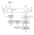
- Fig. 7 is a block diagram of such an inverter control device.
- a main circuit includes an AC power source 51, a diode bridge 52 for converting an AC power to a DC power, a reactor 61 having a small capacity less than 2mH, a capacitor 62 having a small capacity less than 100 ⁇ F, an inverter 53 for converting a DC power to an AC power, and a motor 54 driven with the AC power converted by the inverter 53.
- a control circuit includes a motor voltage command preparing means 64 for preparing a voltage command value for each phase of the motor 54 depending on a speed command ⁇ * for the motor 54 given from outside, a PN voltage detecting means 65 for detecting a DC voltage value applied to the inverter 53, and a PN voltage predicting means 69 for calculating a predicted DC voltage value at a timing when the inverter 53 actually outputs a voltage.
- the control circuit also includes a PN voltage correcting means 66 for first deriving a PN voltage correction factor by dividing a previously set DC voltage reference value of the inverter 53 by the predicted DC voltage value calculated by the PN voltage predicting means 69, and for subsequently setting, when the detected DC voltage value is less than zero, a previously set maximum value of the PN voltage correction factor to the PN voltage correction factor.
- the control circuit further includes a motor voltage command correcting means 67 for correcting the voltage command value for each phase by multiplying the voltage command value for each phase, prepared by the motor voltage command preparing means 64, by the PN voltage correction factor outputted from the PN voltage correcting means 66, and a PWM control means 68 for producing a PWM signal for the inverter 53 so that a motor voltage command correction value obtained by the motor voltage command correcting means 67 may be applied to the motor 54.
- a motor voltage command correcting means 67 for correcting the voltage command value for each phase by multiplying the voltage command value for each phase, prepared by the motor voltage command preparing means 64, by the PN voltage correction factor outputted from the PN voltage correcting means 66
- PWM control means 68 for producing a PWM signal for the inverter 53 so that a motor voltage command correction value obtained by the motor voltage command correcting means 67 may be applied to the motor 54.
- the use of the small-capacity capacitor and the small-capacity reactor realizes a small-sized, lightweight, and inexpensive inverter control device for drive of the motor, with which even if the motor drive becomes difficult or impossible due to considerable changes in inverter DC voltage, the inverter is operated to make the voltage applied to the motor substantially constant, thereby making it possible to ensure the motor drive.
- the present invention has been developed to overcome the above-described disadvantages.
- the electrical component box for an air conditioner includes a first control substrate having an exothermic element mounted thereon, a first substrate holder disposed above a partition plate, which partitions a compressor and a cooling fan from each other, to hold the first control substrate, a second control substrate having a non-exothermic element mounted thereon, a second substrate holder disposed generally perpendicular to the first substrate holder or generally horizontally on a compressor side with respect to the partition plate to hold the second control substrate, and a set of radiating fins mounted on the first control substrate so as to protrude therefrom on a fan side with respect to the partition plate.
- the size of the electrical component box for an air compressor be reduced, but the size of the air conditioner can also be reduced.
- a first invention includes a first control substrate having an exothermic element mounted thereon, a first substrate holder disposed above a partition plate, which partitions a compressor and a cooling fan from each other, to hold the first control substrate, a second control substrate having a non-exothermic element mounted thereon, a second substrate holder disposed generally perpendicular to the first substrate holder or generally horizontally on a compressor side with respect to the partition plate to hold the second control substrate, and a set of radiating fins mounted on the first control substrate so as to protrude therefrom on a fan side with respect to the partition plate.
- This construction can reduce the size of an electrical component box.
- the second substrate holder provided in the first invention has a slot defined therein into which the second control substrate is inserted.
- a third invention further includes a reactor mounted on the second control substrate. This construction can reduce the size of the electrical component box.
- a fourth invention is directed to an air conditioner including the electrical component box according to any one of the first to third inventions. This invention can reduce the size of the air conditioner. Embodiment 1.
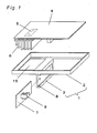
- Fig. 1 is an exploded perspective view depicting a construction of an electrical component box for an air conditioner according to a first embodiment of the present invention.
- the electrical component box 1 is integrally formed of a resinous material and includes a substrate holder 2 constituting a first substrate holder, and a substrate holder 3 constituting a second substrate holder and extending in a direction generally perpendicular to the substrate holder 2 (substantially vertically downwardly).
- a control substrate 4 constituting a first control substrate includes a plurality of electrical components mounted thereon and including an exothermic element 5, and is mounted on the substrate holder 2.
- a set of radiating fins 6 are mounted on the control substrate 4 to radiate heat emitted from the exothermic element 5.
- the exothermic element is an element that gives rise to a considerable power loss and heat generation incidental thereto and, hence, requires radiating fins for cooling.
- Exothermic elements include a diode for use in a rectifying circuit that constitutes an inverter control device for a motor required to drive an air conditioner to convert an AC power to a DC power, as disclosed in Patent Document 2, an IGBT for use in an inverter circuit for converting a DC power to an AC power, and the like.
- a control substrate 7 constituting a second control substrate includes a reactor 9 and a plurality of electrical elements mounted thereon and including no exothermic elements (electrical elements not producing much heat and requiring no radiating fins, or non-exothermic elements).
- This control substrate 7 is inserted into a slot 8 defined in the substrate holder 3. Because of this, the control substrate 4 and the control substrate 7 are arranged generally perpendicular to each other.
- Fig. 2 is a front view of an outdoor unit 10 of an air conditioner provided with the electrical component box according to this embodiment.
- the outdoor unit 10 accommodates a compressor 11 and a cooling fan 12 therein, and the compressor 11 and the cooling fan 12 are separated by a vertically extending partition plate 13.
- the electrical component box 1 is disposed above the partition plate 13 within the outdoor unit 10.
- the control substrate 7 is disposed in a compressor side compartment with respect to the partition plate 13 so as to extend parallel to the partition plate 13.
- the radiating fins 6 protrude downwardly through an opening 15 defined in the substrate holder 2 within a fan side compartment with respect to the partition plate 13. Accordingly, radiation from the radiating fins 6 is promoted by the cooling fan 12 driven by a fan motor 14.
- control substrate 4 the control substrate 7, the compressor 11, and the fan motor 14 are connected to one another by a wire harness or the like.
- control substrate 4 and the control substrate 7 are disposed generally perpendicular to each other, and the reactor 9 is mounted on the control substrate 7.
- This construction can reduce the size of the whole electrical component box, thereby making it possible to locate the electrical component box 1 at a position not interfering with the compressor 11 or the cooling fan 12.
- the outdoor unit 10 can be reduced in size.
- control substrate 7 is attached to the electrical component box 1 by inserting the former into the slot 8 in the latter, attachment of the control substrate 7 is easy.
- Embodiment 2
- Fig. 3 is an exploded perspective view depicting a construction of an electrical component box for an air conditioner according to a second embodiment of the present invention.
- like parts are designated by like reference numerals, and explanation thereof is omitted.
- the electrical component box 101 is integrally formed of a resinous material and includes a substrate holder 102 constituting a first substrate holder, and a substrate holder 103 constituting a second substrate holder and extending in a direction generally parallel to the substrate holder 102.
- a control substrate 104 constituting a first control substrate includes a plurality of electrical components mounted thereon and including an exothermic element 5, and is mounted on the substrate holder 102.
- a set of radiating fins 6 are mounted on the control substrate 104 to radiate heat emitted from the exothermic element 5.
- a control substrate 107 constituting a second control substrate includes a reactor 9 and a plurality of electrical elements mounted thereon and including no exothermic elements. This control substrate 107 is inserted into a slot 108 defined in the substrate holder 103. Because of this, the control substrate 104 and the control substrate 107 are both arranged generally horizontally. As described above, because the reactor 9 can be reduced in size and weight, it can be readily attached to the control substrate 107.
- control substrate 104 and the control substrate 107.
- high lead elements such as, for example, capacitors, reactors, and the like are mounted on the control substrate 104 and the control substrate 107.
- control substrate 104 and the control substrate 107 are both attached to the electrical component box 101 such that an element surface of the former on which the lead elements are mounted and an element surface of the latter on which the lead elements are mounted are opposed to each other and, hence, all the lead elements mounted on the two control substrates 104, 107 are positioned so as not to be in contact with each other.
- control substrate 104 In applications where a single-sided substrate is used for the control substrate 104, and surface-mount elements such as a microcomputer 117 and the like are mounted on the control substrate 104, a space is created on a surface (lead element surface) opposite to the surface on which the surface-mount elements are mounted.
- the control substrate 107 By designing the control substrate 107 such that the high elements mounted thereon and including the reactor 9 are positioned in such a space, the control substrates can be efficiently accommodated in the electrical component box 101.
- Fig. 4 is a front view of an outdoor unit 10 of an air conditioner provided with the electrical component box 101 according to this embodiment.
- the outdoor unit 10 accommodates a compressor 11 and a cooling fan 12 therein, and the compressor 11 and the cooling fan 12 are separated by a vertically extending partition plate 13.
- the electrical component box 101 is disposed above the partition plate 13 within the outdoor unit 10.
- the control substrate 107 is disposed in a compressor side compartment with respect to the partition plate 13.
- the radiating fins 6 protrude downwardly through an opening 15 defined in the substrate holder 102 within a fan side compartment with respect to the partition plate 13. Accordingly, radiation from the radiating fins 6 is promoted by the cooling fan 12 driven by a fan motor 14.
- control substrate 104 the control substrate 107, the compressor 11, and the fan motor 14 are connected to one another by a wire harness or the like.
- control substrate 104 and the control substrate 107 are disposed generally horizontally, and the reactor 9 is mounted on the control substrate 107.
- This construction can reduce the size of the whole electrical component box, thereby making it possible to locate the electrical component box 101 at a position not interfering with the compressor 11 or the cooling fan 12.
- the electrical component box 101 can be efficiently accommodated within a space delimited by the compressor 11, the partition plate 13, and a rear surface (not shown) and a side surface 16 of the outdoor unit 10, the size of the outdoor unit 10 can be reduced.
- control substrate 107 is attached to the electrical component box by inserting the former into the slot 108 in the latter, attachment of the control substrate 107 is easy.
- Fig. 5 is a front view of an outdoor unit 10 of an air conditioner provided with the electrical component box according to this embodiment.
- the electrical component box 17 constituting a first substrate holder and a fixing plate 18 constituting a second substrate holder are separated from each other.
- the electrical component box 17 is disposed above the partition plate 13, while the fixing plate 18 is placed on the partition plate 13 on the side of the compressor 11.
- the electrical component box 17 By arranging the electrical component box 17 above the partition plate 13 and arranging a control substrate 7 on a side surface of the partition plate 13 in the aforementioned manner, not only can the size of the electrical component box 17 be reduced, but the electrical component box 17 and the control substrate 7 can also be efficiently accommodated within a space delimited by the compressor 11, the partition plate 13, and a rear surface (not shown) and a side surface 16 of the outdoor unit 10, thereby making it possible to reduce the size of the outdoor unit 10.
- the electrical component box according to the present invention can be reduced in size, it can be effectively utilized as an electrical component box for an air conditioner.
Landscapes
- Engineering & Computer Science (AREA)
- Chemical & Material Sciences (AREA)
- Combustion & Propulsion (AREA)
- Mechanical Engineering (AREA)
- General Engineering & Computer Science (AREA)
- Cooling Or The Like Of Electrical Apparatus (AREA)
- Inverter Devices (AREA)
Abstract
Description
- The present invention relates to an air conditioner and, more particularly, to an electrical component box for the air conditioner.
- A conventional air conditioner is used with an electrical component box having a control substrate, on which a plurality of electrical components are mounted, to control the air conditioner (see, for example, Patent Document 1).
-
Fig. 6 is an exploded perspective view depicting an example of a construction of an electrical component box as disclosed inPatent Document 1. As shown inFig. 6 , theelectrical component box 21 for an air conditioner includessubstrate holders wiring board 27 mounted horizontally on thesubstrate holder 22 so as to cover an upper surface thereof, and a printedwiring board 30 mounted vertically on thesubstrate holder 23 so as to cover a rear surface thereof. The printedwiring board 27 includes a set of radiatingfins 26 exposed on one side of thesubstrate holder 22 and having exothermicelectronic elements wiring board 30 includes a set of radiatingfins 29 exposed on the rear surface side of thesubstrate holder 23 and having an exothermicelectronic element 28 mounted thereon that is cooled by the cooling fan. - The
substrate holders reactor 31 therein such that an upper surface and a rear surface of thereactor 31 may be covered with the printedwiring board 27 and the printedwiring board 30, respectively. - An inverter control device for driving a motor has been also proposed to control an air conditioner (see, for example, Patent Document 2).
-
Fig. 7 is a block diagram of such an inverter control device. As shown inFig. 7 , a main circuit includes anAC power source 51, adiode bridge 52 for converting an AC power to a DC power, areactor 61 having a small capacity less than 2mH, acapacitor 62 having a small capacity less than 100µF, aninverter 53 for converting a DC power to an AC power, and amotor 54 driven with the AC power converted by theinverter 53. On the other hand, a control circuit includes a motor voltage command preparing means 64 for preparing a voltage command value for each phase of themotor 54 depending on a speed command ω* for themotor 54 given from outside, a PN voltage detecting means 65 for detecting a DC voltage value applied to theinverter 53, and a PN voltage predicting means 69 for calculating a predicted DC voltage value at a timing when theinverter 53 actually outputs a voltage. The control circuit also includes a PN voltage correcting means 66 for first deriving a PN voltage correction factor by dividing a previously set DC voltage reference value of theinverter 53 by the predicted DC voltage value calculated by the PNvoltage predicting means 69, and for subsequently setting, when the detected DC voltage value is less than zero, a previously set maximum value of the PN voltage correction factor to the PN voltage correction factor. The control circuit further includes a motor voltage command correcting means 67 for correcting the voltage command value for each phase by multiplying the voltage command value for each phase, prepared by the motor voltage command preparing means 64, by the PN voltage correction factor outputted from the PN voltage correcting means 66, and a PWM control means 68 for producing a PWM signal for theinverter 53 so that a motor voltage command correction value obtained by the motor voltage command correcting means 67 may be applied to themotor 54. - By this construction, the use of the small-capacity capacitor and the small-capacity reactor realizes a small-sized, lightweight, and inexpensive inverter control device for drive of the motor, with which even if the motor drive becomes difficult or impossible due to considerable changes in inverter DC voltage, the inverter is operated to make the voltage applied to the motor substantially constant, thereby making it possible to ensure the motor drive.
- Patent Document 1: Japanese Laid-Open Patent Publication No.
11-63574 - Patent Document 2: Japanese Laid-Open Patent Publication No.
2005-304248 - In the case of the conventional electrical component box for the air conditioner as described above, however, because the exothermic elements are separately mounted on the first printed wiring board and the second printed wiring board, two sets of radiating fins are required. Also, because the reactor is independently arranged, and the first printed wiring board and the second printed wiring board are arranged so as to cover the reactor, miniaturization of the whole electrical component box may be difficult.
- The present invention has been developed to overcome the above-described disadvantages.
- It is accordingly an objective of the present invention to provide an electrical component box that can be reduced in size.
- In accomplishing the above objective, the electrical component box for an air conditioner according to the present invention includes a first control substrate having an exothermic element mounted thereon, a first substrate holder disposed above a partition plate, which partitions a compressor and a cooling fan from each other, to hold the first control substrate, a second control substrate having a non-exothermic element mounted thereon, a second substrate holder disposed generally perpendicular to the first substrate holder or generally horizontally on a compressor side with respect to the partition plate to hold the second control substrate, and a set of radiating fins mounted on the first control substrate so as to protrude therefrom on a fan side with respect to the partition plate.
- According to the present invention, not only can the size of the electrical component box for an air compressor be reduced, but the size of the air conditioner can also be reduced.
-
-
Fig. 1 . is an exploded perspective view depicting a construction of an electrical component box for an air conditioner according to a first embodiment of the present invention. -
Fig. 2 is a front view of an outdoor unit provided with the electrical component box ofFig. 1 . -
Fig. 3 is an exploded perspective view depicting a construction of an electrical component box for an air conditioner according to a second embodiment of the present invention. -
Fig. 4 is a front view of an outdoor unit provided with the electrical component box ofFig. 3 . -
Fig. 5 is a front view of an outdoor unit provided with an electrical component box according to a third embodiment of the present invention. -
Fig. 6 is an exploded perspective view depicting a construction of a conventional electrical component box for an air conditioner. -
Fig. 7 is a block diagram of a conventional inverter control device for drive of a motor. -
- 1
- Electrical component box
- 2
- Substrate holder
- 3
- Substrate holder
- 4
- Control substrate
- 5
- Exothermic component
- 6
- Radiating fins
- 7
- Control substrate
- 8
- Slot
- 9
- Reactor
- 10
- Outdoor unit
- 11
- Compressor
- 12
- Cooling fan
- 13
- Partition plate
- 14
- Fan motor
- 15
- Opening
- 16
- Side surface of outdoor unit
- 17
- Electrical component box
- 18
- Fixing plate
- 101
- Electrical component box
- 102
- Substrate holder
- 103
- Substrate holder
- A first invention includes a first control substrate having an exothermic element mounted thereon, a first substrate holder disposed above a partition plate, which partitions a compressor and a cooling fan from each other, to hold the first control substrate, a second control substrate having a non-exothermic element mounted thereon, a second substrate holder disposed generally perpendicular to the first substrate holder or generally horizontally on a compressor side with respect to the partition plate to hold the second control substrate, and a set of radiating fins mounted on the first control substrate so as to protrude therefrom on a fan side with respect to the partition plate. This construction can reduce the size of an electrical component box.
- In a second invention, the second substrate holder provided in the first invention has a slot defined therein into which the second control substrate is inserted. By this construction, not only can the size of the electrical component box be reduced, but the second control substrate can also be easily attached.
- In the first or second invention, a third invention further includes a reactor mounted on the second control substrate. This construction can reduce the size of the electrical component box.
- A fourth invention is directed to an air conditioner including the electrical component box according to any one of the first to third inventions. This invention can reduce the size of the air conditioner.
Embodiment 1. -
Fig. 1 is an exploded perspective view depicting a construction of an electrical component box for an air conditioner according to a first embodiment of the present invention. - As shown in
Fig. 1 , theelectrical component box 1 is integrally formed of a resinous material and includes asubstrate holder 2 constituting a first substrate holder, and asubstrate holder 3 constituting a second substrate holder and extending in a direction generally perpendicular to the substrate holder 2 (substantially vertically downwardly). - A
control substrate 4 constituting a first control substrate includes a plurality of electrical components mounted thereon and including anexothermic element 5, and is mounted on thesubstrate holder 2. A set of radiatingfins 6 are mounted on thecontrol substrate 4 to radiate heat emitted from theexothermic element 5. It is noted here that the exothermic element is an element that gives rise to a considerable power loss and heat generation incidental thereto and, hence, requires radiating fins for cooling. Exothermic elements include a diode for use in a rectifying circuit that constitutes an inverter control device for a motor required to drive an air conditioner to convert an AC power to a DC power, as disclosed inPatent Document 2, an IGBT for use in an inverter circuit for converting a DC power to an AC power, and the like. - A
control substrate 7 constituting a second control substrate includes areactor 9 and a plurality of electrical elements mounted thereon and including no exothermic elements (electrical elements not producing much heat and requiring no radiating fins, or non-exothermic elements). Thiscontrol substrate 7 is inserted into aslot 8 defined in thesubstrate holder 3. Because of this, thecontrol substrate 4 and thecontrol substrate 7 are arranged generally perpendicular to each other. By performing the control as proposed inPatent Document 2 in which an inverter control device for drive of a motor is disclosed, even the use of a small-capacity reactor can ensure the motor drive, i.e., the operation of the air conditioner. Accordingly, the reactor can be reduced in size and weight and, hence, the illustratedreactor 9 can be readily attached to thecontrol substrate 7. -
Fig. 2 is a front view of anoutdoor unit 10 of an air conditioner provided with the electrical component box according to this embodiment. As shown inFig. 2 , theoutdoor unit 10 accommodates acompressor 11 and a coolingfan 12 therein, and thecompressor 11 and the coolingfan 12 are separated by a vertically extendingpartition plate 13. Theelectrical component box 1 is disposed above thepartition plate 13 within theoutdoor unit 10. - The
control substrate 7 is disposed in a compressor side compartment with respect to thepartition plate 13 so as to extend parallel to thepartition plate 13. - The radiating
fins 6 protrude downwardly through anopening 15 defined in thesubstrate holder 2 within a fan side compartment with respect to thepartition plate 13. Accordingly, radiation from the radiatingfins 6 is promoted by the coolingfan 12 driven by afan motor 14. - It is noted here that the
control substrate 4, thecontrol substrate 7, thecompressor 11, and thefan motor 14 are connected to one another by a wire harness or the like. - In the
electrical component box 1 structured as described above, thecontrol substrate 4 and thecontrol substrate 7 are disposed generally perpendicular to each other, and thereactor 9 is mounted on thecontrol substrate 7. This construction can reduce the size of the whole electrical component box, thereby making it possible to locate theelectrical component box 1 at a position not interfering with thecompressor 11 or the coolingfan 12. - Also, because the
electrical component box 1 can be efficiently accommodated within a space delimited by thecompressor 11, thepartition plate 13, and a rear surface (not shown) and aside surface 16 of theoutdoor unit 10, theoutdoor unit 10 can be reduced in size. - Further, because the
control substrate 7 is attached to theelectrical component box 1 by inserting the former into theslot 8 in the latter, attachment of thecontrol substrate 7 is easy.Embodiment 2. -
Fig. 3 is an exploded perspective view depicting a construction of an electrical component box for an air conditioner according to a second embodiment of the present invention. In this embodiment and the first embodiment, like parts are designated by like reference numerals, and explanation thereof is omitted. - As shown in
Fig. 3 , theelectrical component box 101 is integrally formed of a resinous material and includes asubstrate holder 102 constituting a first substrate holder, and a substrate holder 103 constituting a second substrate holder and extending in a direction generally parallel to thesubstrate holder 102. - A
control substrate 104 constituting a first control substrate includes a plurality of electrical components mounted thereon and including anexothermic element 5, and is mounted on thesubstrate holder 102. A set of radiatingfins 6 are mounted on thecontrol substrate 104 to radiate heat emitted from theexothermic element 5. - A
control substrate 107 constituting a second control substrate includes areactor 9 and a plurality of electrical elements mounted thereon and including no exothermic elements. Thiscontrol substrate 107 is inserted into aslot 108 defined in the substrate holder 103. Because of this, thecontrol substrate 104 and thecontrol substrate 107 are both arranged generally horizontally. As described above, because thereactor 9 can be reduced in size and weight, it can be readily attached to thecontrol substrate 107. - It is noted here that high lead elements such as, for example, capacitors, reactors, and the like are mounted on the
control substrate 104 and thecontrol substrate 107. - The
control substrate 104 and thecontrol substrate 107 are both attached to theelectrical component box 101 such that an element surface of the former on which the lead elements are mounted and an element surface of the latter on which the lead elements are mounted are opposed to each other and, hence, all the lead elements mounted on the twocontrol substrates - By way of example, in applications where a single-sided substrate is used for the
control substrate 104, and surface-mount elements such as amicrocomputer 117 and the like are mounted on thecontrol substrate 104, a space is created on a surface (lead element surface) opposite to the surface on which the surface-mount elements are mounted. By designing thecontrol substrate 107 such that the high elements mounted thereon and including thereactor 9 are positioned in such a space, the control substrates can be efficiently accommodated in theelectrical component box 101. -
Fig. 4 is a front view of anoutdoor unit 10 of an air conditioner provided with theelectrical component box 101 according to this embodiment. As shown inFig. 4 , theoutdoor unit 10 accommodates acompressor 11 and a coolingfan 12 therein, and thecompressor 11 and the coolingfan 12 are separated by a vertically extendingpartition plate 13. Theelectrical component box 101 is disposed above thepartition plate 13 within theoutdoor unit 10. - The
control substrate 107 is disposed in a compressor side compartment with respect to thepartition plate 13. The radiatingfins 6 protrude downwardly through anopening 15 defined in thesubstrate holder 102 within a fan side compartment with respect to thepartition plate 13. Accordingly, radiation from the radiatingfins 6 is promoted by the coolingfan 12 driven by afan motor 14. - It is noted here that the
control substrate 104, thecontrol substrate 107, thecompressor 11, and thefan motor 14 are connected to one another by a wire harness or the like. - In the
electrical component box 101 structured as described above, thecontrol substrate 104 and thecontrol substrate 107 are disposed generally horizontally, and thereactor 9 is mounted on thecontrol substrate 107. This construction can reduce the size of the whole electrical component box, thereby making it possible to locate theelectrical component box 101 at a position not interfering with thecompressor 11 or the coolingfan 12. - Also, because the
electrical component box 101 can be efficiently accommodated within a space delimited by thecompressor 11, thepartition plate 13, and a rear surface (not shown) and aside surface 16 of theoutdoor unit 10, the size of theoutdoor unit 10 can be reduced. - Further, because the
control substrate 107 is attached to the electrical component box by inserting the former into theslot 108 in the latter, attachment of thecontrol substrate 107 is easy.Embodiment 3. - An electrical component box for an air conditioner according to a third embodiment of the present invention is explained hereinafter with reference to the drawings. In this embodiment and the first embodiment, like parts are designated by like reference numerals, and explanation thereof is omitted.
-
Fig. 5 is a front view of anoutdoor unit 10 of an air conditioner provided with the electrical component box according to this embodiment. - In this embodiment as shown in
Fig. 5 , theelectrical component box 17 constituting a first substrate holder and a fixingplate 18 constituting a second substrate holder are separated from each other. Theelectrical component box 17 is disposed above thepartition plate 13, while the fixingplate 18 is placed on thepartition plate 13 on the side of thecompressor 11. - By arranging the
electrical component box 17 above thepartition plate 13 and arranging acontrol substrate 7 on a side surface of thepartition plate 13 in the aforementioned manner, not only can the size of theelectrical component box 17 be reduced, but theelectrical component box 17 and thecontrol substrate 7 can also be efficiently accommodated within a space delimited by thecompressor 11, thepartition plate 13, and a rear surface (not shown) and aside surface 16 of theoutdoor unit 10, thereby making it possible to reduce the size of theoutdoor unit 10. - As described hereinabove, because the electrical component box according to the present invention can be reduced in size, it can be effectively utilized as an electrical component box for an air conditioner.
Claims (4)
- An electrical component box for an air conditioner that includes a compressor and a cooling fan separated from each other by a partition plate, said electrical component box comprising:a first control substrate having an exothermic element mounted thereon;a first substrate holder disposed above the partition plate to hold the first control substrate;a second control substrate having a non-exothermic element mounted thereon;a second substrate holder disposed generally perpendicular to the first substrate holder or generally horizontally on a compressor side with respect to the partition plate to hold the second control substrate; anda set of radiating fins mounted on the first control substrate so as to protrude therefrom on a fan side with respect to the partition plate.
- The electrical component box for an air conditioner according to claim 1, wherein the second substrate holder has a slot defined therein into which the second control substrate is inserted.
- The electrical component box for an air conditioner according to claim 1 or 2, further comprising a reactor mounted on the second control substrate.
- An air conditioner comprising the electrical component box according to any one of claims 1 to 3.
Applications Claiming Priority (2)
| Application Number | Priority Date | Filing Date | Title |
|---|---|---|---|
| JP2007101528 | 2007-04-09 | ||
| PCT/JP2008/000841 WO2008126390A1 (en) | 2007-04-09 | 2008-04-01 | Electrical component box for air conditioning apparatus and air conditioning apparatus provided with the electrical component box |
Publications (3)
| Publication Number | Publication Date |
|---|---|
| EP2146151A1 true EP2146151A1 (en) | 2010-01-20 |
| EP2146151A4 EP2146151A4 (en) | 2013-07-24 |
| EP2146151B1 EP2146151B1 (en) | 2018-10-17 |
Family
ID=39863550
Family Applications (1)
| Application Number | Title | Priority Date | Filing Date |
|---|---|---|---|
| EP08738453.3A Not-in-force EP2146151B1 (en) | 2007-04-09 | 2008-04-01 | Electrical component box and air conditioner having same |
Country Status (5)
| Country | Link |
|---|---|
| EP (1) | EP2146151B1 (en) |
| JP (1) | JPWO2008126390A1 (en) |
| CN (1) | CN101680669B (en) |
| MY (1) | MY169630A (en) |
| WO (1) | WO2008126390A1 (en) |
Cited By (7)
| Publication number | Priority date | Publication date | Assignee | Title |
|---|---|---|---|---|
| JP2012159224A (en) * | 2011-01-31 | 2012-08-23 | Fujitsu General Ltd | Air conditioner outdoor unit |
| EP2985537A1 (en) * | 2014-08-04 | 2016-02-17 | Mitsubishi Electric Corporation | Heat source side unit for air conditioning apparatus |
| US20190024911A1 (en) * | 2016-03-04 | 2019-01-24 | Mitsubishi Electric Corporation | Electrical component module, and outdoor unit of air-conditioning apparatus |
| US10746418B2 (en) | 2015-11-06 | 2020-08-18 | Mitsubishi Electric Corporation | Outdoor unit and air-conditioning apparatus using the same |
| CN112789449A (en) * | 2018-10-11 | 2021-05-11 | 三菱电机株式会社 | Outdoor machine |
| US11339977B2 (en) | 2019-09-06 | 2022-05-24 | Carrier Corporation | Apparatus and method for providing adequate cooling inside an electrical equipment |
| US12526968B2 (en) | 2022-01-06 | 2026-01-13 | Carrier Corporation | Heatsink for power electronics cooling |
Families Citing this family (14)
| Publication number | Priority date | Publication date | Assignee | Title |
|---|---|---|---|---|
| JP5873994B2 (en) * | 2011-04-28 | 2016-03-01 | パナソニックIpマネジメント株式会社 | Air conditioner outdoor unit |
| JP2014096968A (en) * | 2012-11-12 | 2014-05-22 | Murata Mfg Co Ltd | Inverter device |
| CN103822315B (en) * | 2012-11-16 | 2016-07-13 | 珠海格力电器股份有限公司 | Outdoor machine of air conditioner |
| KR102166764B1 (en) | 2013-10-10 | 2020-10-19 | 삼성전자주식회사 | Control box and outdoor unit for air conditioner |
| CN204335267U (en) * | 2015-01-05 | 2015-05-13 | 广东美的制冷设备有限公司 | Air conditioner and its electric control box assembly |
| EP3330623A4 (en) * | 2015-07-31 | 2019-03-20 | Hitachi-Johnson Controls Air Conditioning, Inc. | INDOOR UNIT FOR AIR CONDITIONER, AND AIR CONDITIONER |
| JP6513284B2 (en) * | 2016-03-14 | 2019-05-15 | 三菱電機株式会社 | Outdoor unit of air conditioner |
| JPWO2018062170A1 (en) * | 2016-09-27 | 2019-01-10 | 三菱電機株式会社 | Air conditioner outdoor unit and air conditioner |
| CN106793690B (en) * | 2016-12-19 | 2019-11-26 | 四川长虹空调有限公司 | Convertible frequency air-conditioner heat spreader structures |
| WO2018179083A1 (en) * | 2017-03-28 | 2018-10-04 | 三菱電機株式会社 | Refrigeration cycle device |
| JP6882716B2 (en) * | 2017-04-28 | 2021-06-02 | 株式会社富士通ゼネラル | Outdoor unit of air conditioner |
| JP2018189263A (en) * | 2017-04-28 | 2018-11-29 | 株式会社富士通ゼネラル | Air conditioner outdoor unit |
| JP7770779B2 (en) * | 2021-04-14 | 2025-11-17 | 三菱重工サーマルシステムズ株式会社 | outdoor unit |
| CN116437624A (en) | 2022-01-11 | 2023-07-14 | 开利公司 | mechanical enclosure |
Family Cites Families (6)
| Publication number | Priority date | Publication date | Assignee | Title |
|---|---|---|---|---|
| JPH01163574A (en) | 1987-12-18 | 1989-06-27 | Sanyo Electric Co Ltd | Cooling vessel |
| JP3665450B2 (en) * | 1997-08-25 | 2005-06-29 | 三菱電機株式会社 | Air conditioner outdoor unit |
| JP2000074422A (en) | 1998-09-02 | 2000-03-14 | Toshiba Corp | Control device for air conditioner |
| JP2001317767A (en) * | 2000-05-09 | 2001-11-16 | Mitsubishi Electric Corp | Outdoor unit of air conditioner |
| JP4660130B2 (en) * | 2003-09-30 | 2011-03-30 | 三洋電機株式会社 | Air conditioner outdoor unit |
| JP2005304248A (en) | 2004-04-15 | 2005-10-27 | Matsushita Electric Ind Co Ltd | Motor drive inverter control device and electrical equipment |
-
2008
- 2008-04-01 CN CN2008800109702A patent/CN101680669B/en not_active Expired - Fee Related
- 2008-04-01 WO PCT/JP2008/000841 patent/WO2008126390A1/en not_active Ceased
- 2008-04-01 MY MYPI20094197A patent/MY169630A/en unknown
- 2008-04-01 JP JP2009508907A patent/JPWO2008126390A1/en active Pending
- 2008-04-01 EP EP08738453.3A patent/EP2146151B1/en not_active Not-in-force
Cited By (7)
| Publication number | Priority date | Publication date | Assignee | Title |
|---|---|---|---|---|
| JP2012159224A (en) * | 2011-01-31 | 2012-08-23 | Fujitsu General Ltd | Air conditioner outdoor unit |
| EP2985537A1 (en) * | 2014-08-04 | 2016-02-17 | Mitsubishi Electric Corporation | Heat source side unit for air conditioning apparatus |
| US10746418B2 (en) | 2015-11-06 | 2020-08-18 | Mitsubishi Electric Corporation | Outdoor unit and air-conditioning apparatus using the same |
| US20190024911A1 (en) * | 2016-03-04 | 2019-01-24 | Mitsubishi Electric Corporation | Electrical component module, and outdoor unit of air-conditioning apparatus |
| CN112789449A (en) * | 2018-10-11 | 2021-05-11 | 三菱电机株式会社 | Outdoor machine |
| US11339977B2 (en) | 2019-09-06 | 2022-05-24 | Carrier Corporation | Apparatus and method for providing adequate cooling inside an electrical equipment |
| US12526968B2 (en) | 2022-01-06 | 2026-01-13 | Carrier Corporation | Heatsink for power electronics cooling |
Also Published As
| Publication number | Publication date |
|---|---|
| CN101680669B (en) | 2012-06-13 |
| EP2146151B1 (en) | 2018-10-17 |
| WO2008126390A1 (en) | 2008-10-23 |
| MY169630A (en) | 2019-04-24 |
| JPWO2008126390A1 (en) | 2010-07-22 |
| CN101680669A (en) | 2010-03-24 |
| EP2146151A4 (en) | 2013-07-24 |
Similar Documents
| Publication | Publication Date | Title |
|---|---|---|
| EP2146151B1 (en) | Electrical component box and air conditioner having same | |
| US6501662B2 (en) | Motor driving inverter | |
| US7746648B2 (en) | Modular heat-radiation structure and controller including the structure | |
| JP6173763B2 (en) | Inverter-integrated electric compressor | |
| JP5529477B2 (en) | Inverter-integrated electric compressor | |
| JP5704760B2 (en) | Quick charger | |
| JP2017172509A (en) | Inverter integrated type electric compressor | |
| JP7012874B2 (en) | Outdoor unit of air conditioner | |
| JP2008261508A (en) | Air conditioner electrical component box and air conditioner equipped with the same | |
| JP4093479B2 (en) | Power supply | |
| WO2018088317A1 (en) | Capacitor unit, and electric compressor | |
| JP6723142B2 (en) | Capacitor unit, electric compressor | |
| JP2023057988A (en) | Power conversion device, connector fixing structure, and method for manufacturing power conversion device | |
| EP2816591B1 (en) | Electrical component cooling device and heat source equipment for a refrigeration cycle apparatus provided with same | |
| JP6028222B2 (en) | Electrical equipment | |
| JP2013085399A (en) | Quick charger | |
| JP6492822B2 (en) | Rotating electrical machine structure | |
| JP6451571B2 (en) | Power converter | |
| JP2018076848A (en) | Motor compressor | |
| CN105827178B (en) | Motor control device | |
| CN111865105A (en) | Inverter unit | |
| CN112655086A (en) | Control device and maintenance method for control device | |
| JP2003199360A (en) | Power supply | |
| JP6610765B2 (en) | Power converter | |
| CN118870705A (en) | Power conversion device and motor unit |
Legal Events
| Date | Code | Title | Description |
|---|---|---|---|
| PUAI | Public reference made under article 153(3) epc to a published international application that has entered the european phase |
Free format text: ORIGINAL CODE: 0009012 |
|
| 17P | Request for examination filed |
Effective date: 20091109 |
|
| AK | Designated contracting states |
Kind code of ref document: A1 Designated state(s): AT BE BG CH CY CZ DE DK EE ES FI FR GB GR HR HU IE IS IT LI LT LU LV MC MT NL NO PL PT RO SE SI SK TR |
|
| AX | Request for extension of the european patent |
Extension state: AL BA MK RS |
|
| DAX | Request for extension of the european patent (deleted) | ||
| A4 | Supplementary search report drawn up and despatched |
Effective date: 20130626 |
|
| RIC1 | Information provided on ipc code assigned before grant |
Ipc: F24F 1/24 20110101AFI20130620BHEP Ipc: F24F 1/22 20110101ALI20130620BHEP |
|
| STAA | Information on the status of an ep patent application or granted ep patent |
Free format text: STATUS: EXAMINATION IS IN PROGRESS |
|
| 17Q | First examination report despatched |
Effective date: 20161110 |
|
| GRAP | Despatch of communication of intention to grant a patent |
Free format text: ORIGINAL CODE: EPIDOSNIGR1 |
|
| STAA | Information on the status of an ep patent application or granted ep patent |
Free format text: STATUS: GRANT OF PATENT IS INTENDED |
|
| INTG | Intention to grant announced |
Effective date: 20171115 |
|
| GRAJ | Information related to disapproval of communication of intention to grant by the applicant or resumption of examination proceedings by the epo deleted |
Free format text: ORIGINAL CODE: EPIDOSDIGR1 |
|
| STAA | Information on the status of an ep patent application or granted ep patent |
Free format text: STATUS: EXAMINATION IS IN PROGRESS |
|
| INTC | Intention to grant announced (deleted) | ||
| RIN1 | Information on inventor provided before grant (corrected) |
Inventor name: SUGIMOTO, TOMOHIRO Inventor name: OGAWA, MASANORI |
|
| GRAP | Despatch of communication of intention to grant a patent |
Free format text: ORIGINAL CODE: EPIDOSNIGR1 |
|
| STAA | Information on the status of an ep patent application or granted ep patent |
Free format text: STATUS: GRANT OF PATENT IS INTENDED |
|
| INTG | Intention to grant announced |
Effective date: 20180430 |
|
| GRAS | Grant fee paid |
Free format text: ORIGINAL CODE: EPIDOSNIGR3 |
|
| GRAA | (expected) grant |
Free format text: ORIGINAL CODE: 0009210 |
|
| STAA | Information on the status of an ep patent application or granted ep patent |
Free format text: STATUS: THE PATENT HAS BEEN GRANTED |
|
| AK | Designated contracting states |
Kind code of ref document: B1 Designated state(s): AT BE BG CH CY CZ DE DK EE ES FI FR GB GR HR HU IE IS IT LI LT LU LV MC MT NL NO PL PT RO SE SI SK TR |
|
| REG | Reference to a national code |
Ref country code: GB Ref legal event code: FG4D |
|
| REG | Reference to a national code |
Ref country code: CH Ref legal event code: EP |
|
| REG | Reference to a national code |
Ref country code: IE Ref legal event code: FG4D |
|
| REG | Reference to a national code |
Ref country code: DE Ref legal event code: R096 Ref document number: 602008057446 Country of ref document: DE Ref country code: AT Ref legal event code: REF Ref document number: 1054517 Country of ref document: AT Kind code of ref document: T Effective date: 20181115 |
|
| REG | Reference to a national code |
Ref country code: NL Ref legal event code: MP Effective date: 20181017 |
|
| REG | Reference to a national code |
Ref country code: LT Ref legal event code: MG4D |
|
| REG | Reference to a national code |
Ref country code: AT Ref legal event code: MK05 Ref document number: 1054517 Country of ref document: AT Kind code of ref document: T Effective date: 20181017 |
|
| PG25 | Lapsed in a contracting state [announced via postgrant information from national office to epo] |
Ref country code: NL Free format text: LAPSE BECAUSE OF FAILURE TO SUBMIT A TRANSLATION OF THE DESCRIPTION OR TO PAY THE FEE WITHIN THE PRESCRIBED TIME-LIMIT Effective date: 20181017 |
|
| PG25 | Lapsed in a contracting state [announced via postgrant information from national office to epo] |
Ref country code: LV Free format text: LAPSE BECAUSE OF FAILURE TO SUBMIT A TRANSLATION OF THE DESCRIPTION OR TO PAY THE FEE WITHIN THE PRESCRIBED TIME-LIMIT Effective date: 20181017 Ref country code: AT Free format text: LAPSE BECAUSE OF FAILURE TO SUBMIT A TRANSLATION OF THE DESCRIPTION OR TO PAY THE FEE WITHIN THE PRESCRIBED TIME-LIMIT Effective date: 20181017 Ref country code: ES Free format text: LAPSE BECAUSE OF FAILURE TO SUBMIT A TRANSLATION OF THE DESCRIPTION OR TO PAY THE FEE WITHIN THE PRESCRIBED TIME-LIMIT Effective date: 20181017 Ref country code: LT Free format text: LAPSE BECAUSE OF FAILURE TO SUBMIT A TRANSLATION OF THE DESCRIPTION OR TO PAY THE FEE WITHIN THE PRESCRIBED TIME-LIMIT Effective date: 20181017 Ref country code: NO Free format text: LAPSE BECAUSE OF FAILURE TO SUBMIT A TRANSLATION OF THE DESCRIPTION OR TO PAY THE FEE WITHIN THE PRESCRIBED TIME-LIMIT Effective date: 20190117 Ref country code: IS Free format text: LAPSE BECAUSE OF FAILURE TO SUBMIT A TRANSLATION OF THE DESCRIPTION OR TO PAY THE FEE WITHIN THE PRESCRIBED TIME-LIMIT Effective date: 20190217 Ref country code: FI Free format text: LAPSE BECAUSE OF FAILURE TO SUBMIT A TRANSLATION OF THE DESCRIPTION OR TO PAY THE FEE WITHIN THE PRESCRIBED TIME-LIMIT Effective date: 20181017 Ref country code: BG Free format text: LAPSE BECAUSE OF FAILURE TO SUBMIT A TRANSLATION OF THE DESCRIPTION OR TO PAY THE FEE WITHIN THE PRESCRIBED TIME-LIMIT Effective date: 20190117 Ref country code: PL Free format text: LAPSE BECAUSE OF FAILURE TO SUBMIT A TRANSLATION OF THE DESCRIPTION OR TO PAY THE FEE WITHIN THE PRESCRIBED TIME-LIMIT Effective date: 20181017 Ref country code: HR Free format text: LAPSE BECAUSE OF FAILURE TO SUBMIT A TRANSLATION OF THE DESCRIPTION OR TO PAY THE FEE WITHIN THE PRESCRIBED TIME-LIMIT Effective date: 20181017 |
|
| PG25 | Lapsed in a contracting state [announced via postgrant information from national office to epo] |
Ref country code: SE Free format text: LAPSE BECAUSE OF FAILURE TO SUBMIT A TRANSLATION OF THE DESCRIPTION OR TO PAY THE FEE WITHIN THE PRESCRIBED TIME-LIMIT Effective date: 20181017 Ref country code: PT Free format text: LAPSE BECAUSE OF FAILURE TO SUBMIT A TRANSLATION OF THE DESCRIPTION OR TO PAY THE FEE WITHIN THE PRESCRIBED TIME-LIMIT Effective date: 20190217 Ref country code: GR Free format text: LAPSE BECAUSE OF FAILURE TO SUBMIT A TRANSLATION OF THE DESCRIPTION OR TO PAY THE FEE WITHIN THE PRESCRIBED TIME-LIMIT Effective date: 20190118 |
|
| REG | Reference to a national code |
Ref country code: DE Ref legal event code: R097 Ref document number: 602008057446 Country of ref document: DE |
|
| PG25 | Lapsed in a contracting state [announced via postgrant information from national office to epo] |
Ref country code: DK Free format text: LAPSE BECAUSE OF FAILURE TO SUBMIT A TRANSLATION OF THE DESCRIPTION OR TO PAY THE FEE WITHIN THE PRESCRIBED TIME-LIMIT Effective date: 20181017 Ref country code: CZ Free format text: LAPSE BECAUSE OF FAILURE TO SUBMIT A TRANSLATION OF THE DESCRIPTION OR TO PAY THE FEE WITHIN THE PRESCRIBED TIME-LIMIT Effective date: 20181017 Ref country code: IT Free format text: LAPSE BECAUSE OF FAILURE TO SUBMIT A TRANSLATION OF THE DESCRIPTION OR TO PAY THE FEE WITHIN THE PRESCRIBED TIME-LIMIT Effective date: 20181017 |
|
| PLBE | No opposition filed within time limit |
Free format text: ORIGINAL CODE: 0009261 |
|
| STAA | Information on the status of an ep patent application or granted ep patent |
Free format text: STATUS: NO OPPOSITION FILED WITHIN TIME LIMIT |
|
| PG25 | Lapsed in a contracting state [announced via postgrant information from national office to epo] |
Ref country code: RO Free format text: LAPSE BECAUSE OF FAILURE TO SUBMIT A TRANSLATION OF THE DESCRIPTION OR TO PAY THE FEE WITHIN THE PRESCRIBED TIME-LIMIT Effective date: 20181017 Ref country code: EE Free format text: LAPSE BECAUSE OF FAILURE TO SUBMIT A TRANSLATION OF THE DESCRIPTION OR TO PAY THE FEE WITHIN THE PRESCRIBED TIME-LIMIT Effective date: 20181017 Ref country code: SK Free format text: LAPSE BECAUSE OF FAILURE TO SUBMIT A TRANSLATION OF THE DESCRIPTION OR TO PAY THE FEE WITHIN THE PRESCRIBED TIME-LIMIT Effective date: 20181017 |
|
| 26N | No opposition filed |
Effective date: 20190718 |
|
| PG25 | Lapsed in a contracting state [announced via postgrant information from national office to epo] |
Ref country code: SI Free format text: LAPSE BECAUSE OF FAILURE TO SUBMIT A TRANSLATION OF THE DESCRIPTION OR TO PAY THE FEE WITHIN THE PRESCRIBED TIME-LIMIT Effective date: 20181017 |
|
| REG | Reference to a national code |
Ref country code: CH Ref legal event code: PL |
|
| REG | Reference to a national code |
Ref country code: BE Ref legal event code: MM Effective date: 20190430 |
|
| GBPC | Gb: european patent ceased through non-payment of renewal fee |
Effective date: 20190401 |
|
| PG25 | Lapsed in a contracting state [announced via postgrant information from national office to epo] |
Ref country code: LU Free format text: LAPSE BECAUSE OF NON-PAYMENT OF DUE FEES Effective date: 20190401 Ref country code: MC Free format text: LAPSE BECAUSE OF FAILURE TO SUBMIT A TRANSLATION OF THE DESCRIPTION OR TO PAY THE FEE WITHIN THE PRESCRIBED TIME-LIMIT Effective date: 20181017 |
|
| PG25 | Lapsed in a contracting state [announced via postgrant information from national office to epo] |
Ref country code: GB Free format text: LAPSE BECAUSE OF NON-PAYMENT OF DUE FEES Effective date: 20190401 Ref country code: CH Free format text: LAPSE BECAUSE OF NON-PAYMENT OF DUE FEES Effective date: 20190430 Ref country code: LI Free format text: LAPSE BECAUSE OF NON-PAYMENT OF DUE FEES Effective date: 20190430 |
|
| PG25 | Lapsed in a contracting state [announced via postgrant information from national office to epo] |
Ref country code: FR Free format text: LAPSE BECAUSE OF NON-PAYMENT OF DUE FEES Effective date: 20190430 Ref country code: BE Free format text: LAPSE BECAUSE OF NON-PAYMENT OF DUE FEES Effective date: 20190430 |
|
| PG25 | Lapsed in a contracting state [announced via postgrant information from national office to epo] |
Ref country code: TR Free format text: LAPSE BECAUSE OF FAILURE TO SUBMIT A TRANSLATION OF THE DESCRIPTION OR TO PAY THE FEE WITHIN THE PRESCRIBED TIME-LIMIT Effective date: 20181017 |
|
| PG25 | Lapsed in a contracting state [announced via postgrant information from national office to epo] |
Ref country code: IE Free format text: LAPSE BECAUSE OF NON-PAYMENT OF DUE FEES Effective date: 20190401 |
|
| PG25 | Lapsed in a contracting state [announced via postgrant information from national office to epo] |
Ref country code: CY Free format text: LAPSE BECAUSE OF FAILURE TO SUBMIT A TRANSLATION OF THE DESCRIPTION OR TO PAY THE FEE WITHIN THE PRESCRIBED TIME-LIMIT Effective date: 20181017 |
|
| PG25 | Lapsed in a contracting state [announced via postgrant information from national office to epo] |
Ref country code: HU Free format text: LAPSE BECAUSE OF FAILURE TO SUBMIT A TRANSLATION OF THE DESCRIPTION OR TO PAY THE FEE WITHIN THE PRESCRIBED TIME-LIMIT; INVALID AB INITIO Effective date: 20080401 Ref country code: MT Free format text: LAPSE BECAUSE OF FAILURE TO SUBMIT A TRANSLATION OF THE DESCRIPTION OR TO PAY THE FEE WITHIN THE PRESCRIBED TIME-LIMIT Effective date: 20181017 |
|
| PGFP | Annual fee paid to national office [announced via postgrant information from national office to epo] |
Ref country code: DE Payment date: 20240418 Year of fee payment: 17 |
|
| REG | Reference to a national code |
Ref country code: DE Ref legal event code: R119 Ref document number: 602008057446 Country of ref document: DE |
|
| PG25 | Lapsed in a contracting state [announced via postgrant information from national office to epo] |
Ref country code: DE Free format text: LAPSE BECAUSE OF NON-PAYMENT OF DUE FEES Effective date: 20251104 |