EP2146064A1 - Exhaust gas purification apparatus for internal combustion engine - Google Patents
Exhaust gas purification apparatus for internal combustion engine Download PDFInfo
- Publication number
- EP2146064A1 EP2146064A1 EP08740143A EP08740143A EP2146064A1 EP 2146064 A1 EP2146064 A1 EP 2146064A1 EP 08740143 A EP08740143 A EP 08740143A EP 08740143 A EP08740143 A EP 08740143A EP 2146064 A1 EP2146064 A1 EP 2146064A1
- Authority
- EP
- European Patent Office
- Prior art keywords
- catalyst
- ammonia
- upper limit
- temperature
- allowable upper
- Prior art date
- Legal status (The legal status is an assumption and is not a legal conclusion. Google has not performed a legal analysis and makes no representation as to the accuracy of the status listed.)
- Granted
Links
Images




Classifications
-
- F—MECHANICAL ENGINEERING; LIGHTING; HEATING; WEAPONS; BLASTING
- F01—MACHINES OR ENGINES IN GENERAL; ENGINE PLANTS IN GENERAL; STEAM ENGINES
- F01N—GAS-FLOW SILENCERS OR EXHAUST APPARATUS FOR MACHINES OR ENGINES IN GENERAL; GAS-FLOW SILENCERS OR EXHAUST APPARATUS FOR INTERNAL-COMBUSTION ENGINES
- F01N3/00—Exhaust or silencing apparatus having means for purifying, rendering innocuous, or otherwise treating exhaust
- F01N3/08—Exhaust or silencing apparatus having means for purifying, rendering innocuous, or otherwise treating exhaust for rendering innocuous
- F01N3/10—Exhaust or silencing apparatus having means for purifying, rendering innocuous, or otherwise treating exhaust for rendering innocuous by thermal or catalytic conversion of noxious components of exhaust
- F01N3/18—Exhaust or silencing apparatus having means for purifying, rendering innocuous, or otherwise treating exhaust for rendering innocuous by thermal or catalytic conversion of noxious components of exhaust characterised by methods of operation; Control
- F01N3/20—Exhaust or silencing apparatus having means for purifying, rendering innocuous, or otherwise treating exhaust for rendering innocuous by thermal or catalytic conversion of noxious components of exhaust characterised by methods of operation; Control specially adapted for catalytic conversion
- F01N3/206—Adding periodically or continuously substances to exhaust gases for promoting purification, e.g. catalytic material in liquid form, NOx reducing agents
- F01N3/208—Control of selective catalytic reduction [SCR], e.g. by adjusting the dosing of reducing agent
-
- B—PERFORMING OPERATIONS; TRANSPORTING
- B01—PHYSICAL OR CHEMICAL PROCESSES OR APPARATUS IN GENERAL
- B01D—SEPARATION
- B01D53/00—Separation of gases or vapours; Recovering vapours of volatile solvents from gases; Chemical or biological purification of waste gases, e.g. engine exhaust gases, smoke, fumes, flue gases, aerosols
- B01D53/34—Chemical or biological purification of waste gases
- B01D53/92—Chemical or biological purification of waste gases of engine exhaust gases
- B01D53/94—Chemical or biological purification of waste gases of engine exhaust gases by catalytic processes
- B01D53/9404—Removing only nitrogen compounds
- B01D53/9409—Nitrogen oxides
-
- B—PERFORMING OPERATIONS; TRANSPORTING
- B01—PHYSICAL OR CHEMICAL PROCESSES OR APPARATUS IN GENERAL
- B01D—SEPARATION
- B01D53/00—Separation of gases or vapours; Recovering vapours of volatile solvents from gases; Chemical or biological purification of waste gases, e.g. engine exhaust gases, smoke, fumes, flue gases, aerosols
- B01D53/34—Chemical or biological purification of waste gases
- B01D53/92—Chemical or biological purification of waste gases of engine exhaust gases
- B01D53/94—Chemical or biological purification of waste gases of engine exhaust gases by catalytic processes
- B01D53/9495—Controlling the catalytic process
-
- F—MECHANICAL ENGINEERING; LIGHTING; HEATING; WEAPONS; BLASTING
- F01—MACHINES OR ENGINES IN GENERAL; ENGINE PLANTS IN GENERAL; STEAM ENGINES
- F01N—GAS-FLOW SILENCERS OR EXHAUST APPARATUS FOR MACHINES OR ENGINES IN GENERAL; GAS-FLOW SILENCERS OR EXHAUST APPARATUS FOR INTERNAL-COMBUSTION ENGINES
- F01N13/00—Exhaust or silencing apparatus characterised by constructional features
- F01N13/009—Exhaust or silencing apparatus characterised by constructional features having two or more separate purifying devices arranged in series
-
- F—MECHANICAL ENGINEERING; LIGHTING; HEATING; WEAPONS; BLASTING
- F01—MACHINES OR ENGINES IN GENERAL; ENGINE PLANTS IN GENERAL; STEAM ENGINES
- F01N—GAS-FLOW SILENCERS OR EXHAUST APPARATUS FOR MACHINES OR ENGINES IN GENERAL; GAS-FLOW SILENCERS OR EXHAUST APPARATUS FOR INTERNAL-COMBUSTION ENGINES
- F01N13/00—Exhaust or silencing apparatus characterised by constructional features
- F01N13/009—Exhaust or silencing apparatus characterised by constructional features having two or more separate purifying devices arranged in series
- F01N13/0097—Exhaust or silencing apparatus characterised by constructional features having two or more separate purifying devices arranged in series the purifying devices are arranged in a single housing
-
- F—MECHANICAL ENGINEERING; LIGHTING; HEATING; WEAPONS; BLASTING
- F01—MACHINES OR ENGINES IN GENERAL; ENGINE PLANTS IN GENERAL; STEAM ENGINES
- F01N—GAS-FLOW SILENCERS OR EXHAUST APPARATUS FOR MACHINES OR ENGINES IN GENERAL; GAS-FLOW SILENCERS OR EXHAUST APPARATUS FOR INTERNAL-COMBUSTION ENGINES
- F01N3/00—Exhaust or silencing apparatus having means for purifying, rendering innocuous, or otherwise treating exhaust
- F01N3/08—Exhaust or silencing apparatus having means for purifying, rendering innocuous, or otherwise treating exhaust for rendering innocuous
- F01N3/10—Exhaust or silencing apparatus having means for purifying, rendering innocuous, or otherwise treating exhaust for rendering innocuous by thermal or catalytic conversion of noxious components of exhaust
- F01N3/105—General auxiliary catalysts, e.g. upstream or downstream of the main catalyst
- F01N3/106—Auxiliary oxidation catalysts
-
- F—MECHANICAL ENGINEERING; LIGHTING; HEATING; WEAPONS; BLASTING
- F01—MACHINES OR ENGINES IN GENERAL; ENGINE PLANTS IN GENERAL; STEAM ENGINES
- F01N—GAS-FLOW SILENCERS OR EXHAUST APPARATUS FOR MACHINES OR ENGINES IN GENERAL; GAS-FLOW SILENCERS OR EXHAUST APPARATUS FOR INTERNAL-COMBUSTION ENGINES
- F01N3/00—Exhaust or silencing apparatus having means for purifying, rendering innocuous, or otherwise treating exhaust
- F01N3/08—Exhaust or silencing apparatus having means for purifying, rendering innocuous, or otherwise treating exhaust for rendering innocuous
- F01N3/10—Exhaust or silencing apparatus having means for purifying, rendering innocuous, or otherwise treating exhaust for rendering innocuous by thermal or catalytic conversion of noxious components of exhaust
- F01N3/18—Exhaust or silencing apparatus having means for purifying, rendering innocuous, or otherwise treating exhaust for rendering innocuous by thermal or catalytic conversion of noxious components of exhaust characterised by methods of operation; Control
- F01N3/20—Exhaust or silencing apparatus having means for purifying, rendering innocuous, or otherwise treating exhaust for rendering innocuous by thermal or catalytic conversion of noxious components of exhaust characterised by methods of operation; Control specially adapted for catalytic conversion
- F01N3/206—Adding periodically or continuously substances to exhaust gases for promoting purification, e.g. catalytic material in liquid form, NOx reducing agents
-
- F—MECHANICAL ENGINEERING; LIGHTING; HEATING; WEAPONS; BLASTING
- F01—MACHINES OR ENGINES IN GENERAL; ENGINE PLANTS IN GENERAL; STEAM ENGINES
- F01N—GAS-FLOW SILENCERS OR EXHAUST APPARATUS FOR MACHINES OR ENGINES IN GENERAL; GAS-FLOW SILENCERS OR EXHAUST APPARATUS FOR INTERNAL-COMBUSTION ENGINES
- F01N3/00—Exhaust or silencing apparatus having means for purifying, rendering innocuous, or otherwise treating exhaust
- F01N3/08—Exhaust or silencing apparatus having means for purifying, rendering innocuous, or otherwise treating exhaust for rendering innocuous
- F01N3/10—Exhaust or silencing apparatus having means for purifying, rendering innocuous, or otherwise treating exhaust for rendering innocuous by thermal or catalytic conversion of noxious components of exhaust
- F01N3/18—Exhaust or silencing apparatus having means for purifying, rendering innocuous, or otherwise treating exhaust for rendering innocuous by thermal or catalytic conversion of noxious components of exhaust characterised by methods of operation; Control
- F01N3/20—Exhaust or silencing apparatus having means for purifying, rendering innocuous, or otherwise treating exhaust for rendering innocuous by thermal or catalytic conversion of noxious components of exhaust characterised by methods of operation; Control specially adapted for catalytic conversion
- F01N3/206—Adding periodically or continuously substances to exhaust gases for promoting purification, e.g. catalytic material in liquid form, NOx reducing agents
- F01N3/2066—Selective catalytic reduction [SCR]
- F01N3/2073—Means for generating a reducing substance from the exhaust gases
-
- B—PERFORMING OPERATIONS; TRANSPORTING
- B01—PHYSICAL OR CHEMICAL PROCESSES OR APPARATUS IN GENERAL
- B01D—SEPARATION
- B01D2251/00—Reactants
- B01D2251/20—Reductants
- B01D2251/206—Ammonium compounds
- B01D2251/2067—Urea
-
- B—PERFORMING OPERATIONS; TRANSPORTING
- B01—PHYSICAL OR CHEMICAL PROCESSES OR APPARATUS IN GENERAL
- B01D—SEPARATION
- B01D2258/00—Sources of waste gases
- B01D2258/01—Engine exhaust gases
- B01D2258/014—Stoichiometric gasoline engines
-
- B—PERFORMING OPERATIONS; TRANSPORTING
- B01—PHYSICAL OR CHEMICAL PROCESSES OR APPARATUS IN GENERAL
- B01D—SEPARATION
- B01D53/00—Separation of gases or vapours; Recovering vapours of volatile solvents from gases; Chemical or biological purification of waste gases, e.g. engine exhaust gases, smoke, fumes, flue gases, aerosols
- B01D53/34—Chemical or biological purification of waste gases
- B01D53/92—Chemical or biological purification of waste gases of engine exhaust gases
- B01D53/94—Chemical or biological purification of waste gases of engine exhaust gases by catalytic processes
- B01D53/9459—Removing one or more of nitrogen oxides, carbon monoxide, or hydrocarbons by multiple successive catalytic functions; systems with more than one different function, e.g. zone coated catalysts
- B01D53/9477—Removing one or more of nitrogen oxides, carbon monoxide, or hydrocarbons by multiple successive catalytic functions; systems with more than one different function, e.g. zone coated catalysts with catalysts positioned on separate bricks, e.g. exhaust systems
-
- F—MECHANICAL ENGINEERING; LIGHTING; HEATING; WEAPONS; BLASTING
- F01—MACHINES OR ENGINES IN GENERAL; ENGINE PLANTS IN GENERAL; STEAM ENGINES
- F01N—GAS-FLOW SILENCERS OR EXHAUST APPARATUS FOR MACHINES OR ENGINES IN GENERAL; GAS-FLOW SILENCERS OR EXHAUST APPARATUS FOR INTERNAL-COMBUSTION ENGINES
- F01N2560/00—Exhaust systems with means for detecting or measuring exhaust gas components or characteristics
- F01N2560/06—Exhaust systems with means for detecting or measuring exhaust gas components or characteristics the means being a temperature sensor
-
- F—MECHANICAL ENGINEERING; LIGHTING; HEATING; WEAPONS; BLASTING
- F01—MACHINES OR ENGINES IN GENERAL; ENGINE PLANTS IN GENERAL; STEAM ENGINES
- F01N—GAS-FLOW SILENCERS OR EXHAUST APPARATUS FOR MACHINES OR ENGINES IN GENERAL; GAS-FLOW SILENCERS OR EXHAUST APPARATUS FOR INTERNAL-COMBUSTION ENGINES
- F01N2610/00—Adding substances to exhaust gases
- F01N2610/02—Adding substances to exhaust gases the substance being ammonia or urea
-
- F—MECHANICAL ENGINEERING; LIGHTING; HEATING; WEAPONS; BLASTING
- F01—MACHINES OR ENGINES IN GENERAL; ENGINE PLANTS IN GENERAL; STEAM ENGINES
- F01N—GAS-FLOW SILENCERS OR EXHAUST APPARATUS FOR MACHINES OR ENGINES IN GENERAL; GAS-FLOW SILENCERS OR EXHAUST APPARATUS FOR INTERNAL-COMBUSTION ENGINES
- F01N2610/00—Adding substances to exhaust gases
- F01N2610/14—Arrangements for the supply of substances, e.g. conduits
- F01N2610/1453—Sprayers or atomisers; Arrangement thereof in the exhaust apparatus
- F01N2610/146—Control thereof, e.g. control of injectors or injection valves
-
- F—MECHANICAL ENGINEERING; LIGHTING; HEATING; WEAPONS; BLASTING
- F01—MACHINES OR ENGINES IN GENERAL; ENGINE PLANTS IN GENERAL; STEAM ENGINES
- F01N—GAS-FLOW SILENCERS OR EXHAUST APPARATUS FOR MACHINES OR ENGINES IN GENERAL; GAS-FLOW SILENCERS OR EXHAUST APPARATUS FOR INTERNAL-COMBUSTION ENGINES
- F01N2900/00—Details of electrical control or of the monitoring of the exhaust gas treating apparatus
- F01N2900/06—Parameters used for exhaust control or diagnosing
- F01N2900/14—Parameters used for exhaust control or diagnosing said parameters being related to the exhaust gas
- F01N2900/1402—Exhaust gas composition
-
- F—MECHANICAL ENGINEERING; LIGHTING; HEATING; WEAPONS; BLASTING
- F01—MACHINES OR ENGINES IN GENERAL; ENGINE PLANTS IN GENERAL; STEAM ENGINES
- F01N—GAS-FLOW SILENCERS OR EXHAUST APPARATUS FOR MACHINES OR ENGINES IN GENERAL; GAS-FLOW SILENCERS OR EXHAUST APPARATUS FOR INTERNAL-COMBUSTION ENGINES
- F01N2900/00—Details of electrical control or of the monitoring of the exhaust gas treating apparatus
- F01N2900/06—Parameters used for exhaust control or diagnosing
- F01N2900/16—Parameters used for exhaust control or diagnosing said parameters being related to the exhaust apparatus, e.g. particulate filter or catalyst
- F01N2900/1622—Catalyst reducing agent absorption capacity or consumption amount
-
- F—MECHANICAL ENGINEERING; LIGHTING; HEATING; WEAPONS; BLASTING
- F01—MACHINES OR ENGINES IN GENERAL; ENGINE PLANTS IN GENERAL; STEAM ENGINES
- F01N—GAS-FLOW SILENCERS OR EXHAUST APPARATUS FOR MACHINES OR ENGINES IN GENERAL; GAS-FLOW SILENCERS OR EXHAUST APPARATUS FOR INTERNAL-COMBUSTION ENGINES
- F01N3/00—Exhaust or silencing apparatus having means for purifying, rendering innocuous, or otherwise treating exhaust
- F01N3/02—Exhaust or silencing apparatus having means for purifying, rendering innocuous, or otherwise treating exhaust for cooling, or for removing solid constituents of, exhaust
- F01N3/021—Exhaust or silencing apparatus having means for purifying, rendering innocuous, or otherwise treating exhaust for cooling, or for removing solid constituents of, exhaust by means of filters
- F01N3/033—Exhaust or silencing apparatus having means for purifying, rendering innocuous, or otherwise treating exhaust for cooling, or for removing solid constituents of, exhaust by means of filters in combination with other devices
- F01N3/035—Exhaust or silencing apparatus having means for purifying, rendering innocuous, or otherwise treating exhaust for cooling, or for removing solid constituents of, exhaust by means of filters in combination with other devices with catalytic reactors
-
- Y—GENERAL TAGGING OF NEW TECHNOLOGICAL DEVELOPMENTS; GENERAL TAGGING OF CROSS-SECTIONAL TECHNOLOGIES SPANNING OVER SEVERAL SECTIONS OF THE IPC; TECHNICAL SUBJECTS COVERED BY FORMER USPC CROSS-REFERENCE ART COLLECTIONS [XRACs] AND DIGESTS
- Y02—TECHNOLOGIES OR APPLICATIONS FOR MITIGATION OR ADAPTATION AGAINST CLIMATE CHANGE
- Y02T—CLIMATE CHANGE MITIGATION TECHNOLOGIES RELATED TO TRANSPORTATION
- Y02T10/00—Road transport of goods or passengers
- Y02T10/10—Internal combustion engine [ICE] based vehicles
- Y02T10/12—Improving ICE efficiencies
Definitions
- the present invention relates to an exhaust gas purification system of an internal combustion engine.
- part of the urea fed to the catalyst is stored once in the catalyst. From this stored urea, the urea-derived substance such as ammonia is produced. Part of the urea-derived substances is used for reducing the NOx, while the remainder is discharged from the catalyst without being used for reducing the NOx. In this case, the amount of the urea-derived substances released from the catalyst becomes greater the greater the amount of urea stored in the catalyst. Therefore, when the catalyst stores a large amount of urea, a large amount of urea-derived substances is liable to be undesirably discharged from the catalyst.
- an object of the present invention is to provide an exhaust purification system of an internal combustion engine able to block a large amount of ammonia generating compound from being discharged from a catalyst.
- an exhaust purification system of an internal combustion engine arranging a catalyst suitable for reducing NOx in the exhaust gas by ammonia under an excess of oxygen in an engine exhaust passage
- the system comprising: a feeding means for feeding an ammonia generating compound to the catalyst; and a feed controlling means for controlling the amount of feed of the ammonia generating compound, the catalyst having a function of storing at least part of the ammonia generating compound fed to the catalyst in the catalyst and generating ammonia from the ammonia generating compound stored in the catalyst and using the generated ammonia to reduce the NOx in the exhaust gas
- the system further comprising a judging means for judging if a storage capacity of the catalyst is larger than a preset allowable upper limit capacity, wherein the feed controlling means prohibits the feed of the ammonia generating compound when the storage capacity of the catalyst is larger than the allowable upper limit capacity.
- FIG. 1 shows the case of application of the present invention to a compression ignition type internal combustion engine. Note that the present invention can also be applied to a gasoline engine.
- 1 is an engine body
- 2 is a combustion chamber of each cylinder
- 3 is an electronic control type fuel injector for injecting fuel into each combustion chamber
- 4 is an intake manifold
- 5 is an exhaust manifold.
- the intake manifold 4 is connected through an intake duct 6 to an outlet of a compressor 7a of an exhaust turbocharger 7.
- An inlet of the compressor 7a is connected through an air flow meter 8 to an air cleaner 9.
- an electrical control type throttle valve 10 is arranged inside the intake duct 6, an electrical control type throttle valve 10 is arranged.
- a cooling device 11 is arranged to cool the intake air flowing inside the intake duct 6.
- the engine cooling water is guided into the cooling device 11 where the engine cooling water is used to cool the intake air.
- the exhaust manifold 5 is connected to an inlet of an exhaust turbine 7b of the exhaust turbocharger 7.
- the outlet of the exhaust turbine 7b is connected to an exhaust post-treatment device 20.
- the exhaust manifold 5 and the intake manifold 4 are connected with each other through an exhaust gas recirculation (hereinafter referred to as an "EGR") passage 12.
- EGR exhaust gas recirculation
- an electrical control type EGR control valve 13 is arranged inside the EGR passage 12.
- a cooling device 14 is arranged for cooling the EGR gas flowing through the EGR passage.
- engine cooling water is guided into the cooling device 14 where the engine cooling water is used to cool the EGR gas.
- each fuel injector 3 is connected through a fuel feed tube 15 to a common rail 16.
- This common rail 16 is connected through an electronic control type variable discharge fuel pump 17 to a fuel tank 18.
- the fuel in the fuel tank 18 is fed by the fuel pump 17 inside the common rail 16.
- the fuel fed into the common rail 16 is fed through each fuel feed tube 15 to each fuel injector 3.
- the exhaust post-treatment device 20 is provided with an upstream side catalytic converter 22 connected through an exhaust pipe 21 to an outlet of the exhaust turbine 7b and a downstream side catalytic converter 24 connected through an exhaust pipe 23 to the upstream side catalytic converter 22.
- a catalyst 25 and catalyst 26 are arranged in that order from the upstream side.
- a catalyst 27 and catalyst 28 are arranged in that order from the upstream side.
- the catalysts 25, 26, and 28 are comprised of catalysts having oxidation functions, for example, oxidation catalysts or three-way catalysts.
- the catalyst 27 is comprised of an NOx selective reduction catalyst suitable for reducing the NOx in the exhaust gas by ammonia under an excess of oxygen.
- the catalysts 25, 27, and 28 are carried on honeycomb carriers.
- the catalyst 26 is carried on a particulate filter for trapping particulate in the exhaust gas.
- a temperature sensor 29 for detecting the exhaust gas flowing into the downstream side catalytic converter 24 is arranged. The temperature of the exhaust gas flowing into the downstream side catalytic converter 24 expresses the temperature of the catalyst 27.
- a liquid containing an ammonia generating compound which generates ammonia is stored in a tank 30.
- the liquid containing the ammonia generating compound stored in the tank 30 is fed into the exhaust pipe 23 through a feed pump 31 and an electromagnetically controlled addition control valve 32.
- the electronic control unit 40 is comprised of a digital computer which is provided with components connected to each other by a bidirectional bus 41 such as a ROM (read only memory) 42, RAM (random access memory) 43, CPU (microprocessor) 44, input port 45, and output port 46.
- the air flow meter 8 generates an output voltage proportional to the intake air amount. This output voltage is input through a corresponding AD converter 47 to the input port 45.
- the output signal of the temperature sensor 29 is input through a corresponding AD converter 47 to the input port 45.
- An accelerator pedal 49 has a load sensor 50 connected to it for generating an output voltage proportional to the amount of depression of the accelerator pedal 49. The output voltage of the load sensor 50 is input through a corresponding AD converter 47 to the input port 45.
- the input port 45 has a crank angle sensor 51 connected to it for generating an output pulse each time the crankshaft rotates by for example 30°.
- the output port 46 is connected through a corresponding drive circuit 48 to the fuel injector 3, throttle valve 10 drive device, EGR control valve 13, fuel pump 17, feed pump 31, and addition control valve 32.
- the exhaust pipe 23 upstream of the catalyst 27 is fed a liquid containing an ammonia generating compound.
- the ammonia generating compound able to generate ammonia there are various compounds. Therefore, various compounds can be used as the ammonia generating compound.
- urea is used as the ammonia generating compound.
- an aqueous urea solution is used as the liquid containing the ammonia generating compound. Therefore, below, the present invention will be explained taking as an example the case of feeding an aqueous urea solution into the exhaust pipe 23 upstream of the catalyst 27.
- the catalyst 27 is comprised of a NOx selective reduction catalyst.
- a catalyst V 2 O 5 /TiO 2 using titania as the carrier and carrying vanadium oxide on this carrier hereinafter referred to as a "vanadium titania catalyst”
- a catalyst Cu/ZSM5 using zeolite as the carrier and carrying copper on this carrier hereinafter referred to as a "copper zeolite catalyst”
- the NO contained in the exhaust gas is reduced by the ammonia NH 3 generated from the urea CO(NH 2 ) 2 on the catalyst 27 (for example, 2NH 3 +2NO+1/2O 2 ⁇ 2N 2 +3H 2 O).
- the urea in the fed aqueous urea solution first deposits on the catalyst 27.
- the temperature of the catalyst 27 is high, for example, substantially 350°C or more, the urea thermally decomposes all at once and generates ammonia.
- the urea when the temperature of the catalyst 27 is from about 132°C to about 350°C, the urea is stored once inside the catalyst 27, then ammonia is generated and released a little bit at a time from the urea stored inside the catalyst 27.
- the ammonia is generated in this case probably because the urea morphologically changes in the catalyst 27.
- the urea changes to biuret at about 132°C.
- the biuret changes to cyanuric acid at about 190°C.
- the cyanuric acid changes to cyanic acid or isocyanic acid at about 360°C.
- the urea changes to biuret.
- the biuret changes to cyanuric acid, and the cyanuric acid changes to cyanic acid or isocyanic acid. It is thought that ammonia is generated a little bit at a time in the process of this kind of morphological change.
- the temperature of the catalyst 27 is equal to or lower than about 132°C which is the thermal decomposition temperature of urea, if feeding the aqueous urea solution to the catalyst 27, the urea in the aqueous urea solution will be stored in the catalyst 27. At this time, almost no ammonia is generated from the stored urea.
- the amount of the urea-derived substances discharged from the catalyst 27 becomes greater the greater the amount of urea stored in the catalyst 27. Therefore, if the catalyst 27 stores a large amount of urea, a large amount of urea-derived substances is liable to be undesirably discharged from the catalyst 27.
- the catalyst 27 can only store the urea up to its storage capacity.
- This storage capacity varies in accordance with the atmosphere of the catalyst 27, for example, the temperature of the catalyst 27, therefore when the storage capacity of the catalyst 27 is large, the catalyst 27 can store a large amount of urea, while when the storage capacity of the catalyst 27 is small, the catalyst 27 can only store a small amount of urea.
- the storage capacity SC of the catalyst 27 becomes larger when the temperature TC of the catalyst 27 is high compared to when it is low.
- the storage capacity SC of the catalyst 27 becomes the upper limit amount SCU.
- the temperature TC where the storage capacity SC of the catalyst 27 becomes the allowable upper limit capacity SCU is set as a preset temperature TCX.
- TCX the temperature TC of the catalyst 27 is lower than this preset temperature TCX, it is judged that the storage capacity SC of the catalyst 27 is greater than the allowable upper limit capacity SCU. At this time, the feed of the aqueous urea solution is prohibited.
- the temperature of the catalyst 27 is higher than the preset temperature TCX, it is judged that the storage capacity SC of the catalyst 27 is smaller than the allowable upper limit capacity SCU. At this time, the feed of the aqueous urea solution is allowed.
- aqueous urea solution is fed to the catalyst 27 by an amount corresponding to the amount of NOx discharged from the engine.
- the amount of urea stored in the catalyst 27 will never exceed the allowable upper limit capacity SCU. Therefore, even without finding the amount of urea actually stored in the catalyst 27, it is possible to block a large amount of urea from being stored in the catalyst 27.
- the allowable upper limit capacity SCU may be set in any way.
- the allowable upper limit capacity SCU is set as follows.
- FIG. 3 shows an example of the relationship between the amount Q of urea stored in the catalyst 27 and the concentration CA of ammonia discharged from the catalyst 27 for example at the time of engine acceleration.
- the allowable upper limit capacity SCU is set to the upper limit amount QAU for ammonia. As a result, the concentration of ammonia discharged later from the catalyst 27 is blocked from exceeding the allowable upper limit value CAU.
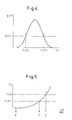
- the NOx purification rate EFF of the catalyst 27, as shown in FIG. 4 becomes lower than the allowable lower limit rate EFFL if the temperature TC of the catalyst 27 is lower than the lower limit temperature TCEL or higher than the upper limit temperature TCEH, and becomes higher than the allowable lower limit rate EEFL if the temperature TC of the catalyst 27 is from the lower limit temperature TCEL to the upper limit temperature TCEH.
- the above-mentioned preset temperature TCX is higher than this lower limit temperature TCEL.
- aqueous urea solution feed start timing after the engine has started.
- X in FIG. 5 when the engine is started, the temperature TC of the catalyst 27 gradually rises. At this time, the feed of the aqueous urea solution is stopped.
- Y in FIG. 5 even if the temperature TC of the catalyst 27 reaches the lower limit temperature TCEL, the feed of the aqueous urea solution is not started.
- Z in FIG. 5 if the temperature TC of the catalyst 27 reaches the preset temperature TCX, the feed of the aqueous urea solution is started.
- the feed of the aqueous urea solution is not started. Only when the temperature TC of the catalyst 27 rises to the temperature able to block the discharge of a large amount of urea-derived substances is the feed of the aqueous urea solution finally started.
- FIG. 6 shows the routine for controlling the feed of the aqueous urea solution in an embodiment according to the present invention. This routine is executed by interruption every fixed time interval.
- step 100 it is judged if the temperature TC of the catalyst 27 is lower than the preset temperature TCX.
- TC ⁇ TCX next the routine proceeds to step 101 where the feed of the aqueous urea solution is allowed.
- step 102 next the routine proceeds to step 102 where the feed of the aqueous urea solution is prohibited.
- the allowable upper limit capacity SCU can be set as follows:
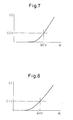
- FIG. 7 shows an example of the relationship between the amount of urea Q stored in the catalyst 27 and the concentration of hydrogen cyanide CC discharged from the catalyst 27 later, for example, at the time of engine acceleration
- FIG. 8 shows an example of the relationship between the amount of urea Q stored in the catalyst 27 and the concentration of isocyanic acid CI discharged from the catalyst 27 later, for example, at the time of engine acceleration.
- the allowable upper limit capacity SCU it is also possible to set the allowable upper limit capacity SCU to the smallest of the upper limit amounts QAU, QCU, and QIU for the ammonia, hydrogen cyanide, and isocyanic acid. By doing this, it is possible to block the ammonia, hydrogen cyanide, and isocyanic acid from exceeding the allowable upper limit values CAU, CCU, and CIU, respectively.
Landscapes
- Engineering & Computer Science (AREA)
- Chemical & Material Sciences (AREA)
- Chemical Kinetics & Catalysis (AREA)
- Combustion & Propulsion (AREA)
- Mechanical Engineering (AREA)
- General Engineering & Computer Science (AREA)
- Health & Medical Sciences (AREA)
- Toxicology (AREA)
- Materials Engineering (AREA)
- Biomedical Technology (AREA)
- Environmental & Geological Engineering (AREA)
- Analytical Chemistry (AREA)
- General Chemical & Material Sciences (AREA)
- Oil, Petroleum & Natural Gas (AREA)
- Exhaust Gas After Treatment (AREA)
- Exhaust Gas Treatment By Means Of Catalyst (AREA)
Abstract
Description
- The present invention relates to an exhaust gas purification system of an internal combustion engine.
- Known in the art is an internal combustion engine arranging a catalyst suitable for reducing NOx in exhaust gas by ammonia in the presence of excess oxygen in an engine exhaust passage, feeding an aqueous urea solution to this catalyst, storing part of the urea fed to the catalyst in the catalyst, and using the ammonia generated from the urea stored in the catalyst to reduce the NOx in the exhaust gas (see
U.S. Patent No. 5,628,186 andWO 99/67511 - In this internal combustion engine, part of the urea fed to the catalyst is stored once in the catalyst. From this stored urea, the urea-derived substance such as ammonia is produced. Part of the urea-derived substances is used for reducing the NOx, while the remainder is discharged from the catalyst without being used for reducing the NOx. In this case, the amount of the urea-derived substances released from the catalyst becomes greater the greater the amount of urea stored in the catalyst. Therefore, when the catalyst stores a large amount of urea, a large amount of urea-derived substances is liable to be undesirably discharged from the catalyst.
- In this regard, it may be considered that, if feeding an aqueous urea solution to the catalyst in an amount commensurate with the amount of NOx discharged from the engine, it is possible to block the catalyst from storing a large amount of urea, therefore it is possible to block a large amount of urea-derived substances from being discharged from the catalyst. However, it is difficult to accurately find the amount of NOx discharged from the engine or the amount of urea commensurate with this. Alternatively, it may be considered that, if finding the amount of urea stored in the catalyst and controlling the amount of aqueous urea solution fed to the catalyst so that this stored amount of urea does not exceed an allowable upper limit, it is possible to block the catalyst from storing a large amount of urea. However, accurately finding the amount of urea stored in the catalyst is difficult. Whatever the case, there is the problem that it is not possible to reliably block the discharge of a large amount of urea-derived substances from the catalyst. If reducing the amount of aqueous urea solution fed to the catalyst, it is possible to block the catalyst from storing a large amount of urea, but in this case it is no longer possible to reduce the NOx well.
- Therefore, an object of the present invention is to provide an exhaust purification system of an internal combustion engine able to block a large amount of ammonia generating compound from being discharged from a catalyst.
- According to the present invention, there is provided an exhaust purification system of an internal combustion engine arranging a catalyst suitable for reducing NOx in the exhaust gas by ammonia under an excess of oxygen in an engine exhaust passage, the system comprising: a feeding means for feeding an ammonia generating compound to the catalyst; and a feed controlling means for controlling the amount of feed of the ammonia generating compound, the catalyst having a function of storing at least part of the ammonia generating compound fed to the catalyst in the catalyst and generating ammonia from the ammonia generating compound stored in the catalyst and using the generated ammonia to reduce the NOx in the exhaust gas, the system further comprising a judging means for judging if a storage capacity of the catalyst is larger than a preset allowable upper limit capacity, wherein the feed controlling means prohibits the feed of the ammonia generating compound when the storage capacity of the catalyst is larger than the allowable upper limit capacity.
-
-
FIG. 1 is an overview of an internal combustion engine,FIG. 2 is a graph showing a storage capacity of a catalyst,FIG. 3 is a graph showing an example of the relationship between an amount of urea stored in the catalyst and a concentration of ammonia later discharged from the catalyst,FIG. 4 is a graph showing an NOx purification rate,FIG. 5 is a time chart for explaining an embodiment according to the present invention,FIG. 6 is a flowchart showing a control routine for feed of an aqueous urea solution,FIG. 7 is a graph showing an example of a relationship of an amount of urea stored in the catalyst and a concentration of hydrogen cyanide later discharged from the catalyst, andFIG. 8 is a graph showing a relationship between an amount of urea stored in a catalyst and a concentration of isocyanic acid later discharged from the catalyst. -
FIG. 1 shows the case of application of the present invention to a compression ignition type internal combustion engine. Note that the present invention can also be applied to a gasoline engine. - Referring to
FIG. 1, 1 is an engine body, 2 is a combustion chamber of each cylinder, 3 is an electronic control type fuel injector for injecting fuel into eachcombustion chamber intake manifold 4 is connected through anintake duct 6 to an outlet of a compressor 7a of anexhaust turbocharger 7. An inlet of the compressor 7a is connected through anair flow meter 8 to anair cleaner 9. Inside theintake duct 6, an electrical controltype throttle valve 10 is arranged. Further, around theintake duct 6, acooling device 11 is arranged to cool the intake air flowing inside theintake duct 6. In the embodiment shown inFIG. 1 , the engine cooling water is guided into thecooling device 11 where the engine cooling water is used to cool the intake air. On the other hand, theexhaust manifold 5 is connected to an inlet of an exhaust turbine 7b of theexhaust turbocharger 7. The outlet of the exhaust turbine 7b is connected to anexhaust post-treatment device 20. - The
exhaust manifold 5 and theintake manifold 4 are connected with each other through an exhaust gas recirculation (hereinafter referred to as an "EGR")passage 12. Inside theEGR passage 12, an electrical control typeEGR control valve 13 is arranged. Further, around the EGRpassage 12, acooling device 14 is arranged for cooling the EGR gas flowing through the EGR passage. In the embodiment shown inFIG. 1 , engine cooling water is guided into thecooling device 14 where the engine cooling water is used to cool the EGR gas. On the other hand, each fuel injector 3 is connected through afuel feed tube 15 to acommon rail 16. Thiscommon rail 16 is connected through an electronic control type variabledischarge fuel pump 17 to afuel tank 18. The fuel in thefuel tank 18 is fed by thefuel pump 17 inside thecommon rail 16. The fuel fed into thecommon rail 16 is fed through eachfuel feed tube 15 to each fuel injector 3. - The
exhaust post-treatment device 20 is provided with an upstream sidecatalytic converter 22 connected through anexhaust pipe 21 to an outlet of the exhaust turbine 7b and a downstream sidecatalytic converter 24 connected through anexhaust pipe 23 to the upstream sidecatalytic converter 22. Inside the upstream sidecatalytic converter 22, a catalyst 25 and catalyst 26 are arranged in that order from the upstream side. Inside the downstream sidecatalytic converter 24, acatalyst 27 andcatalyst 28 are arranged in that order from the upstream side. Thecatalysts 25, 26, and 28 are comprised of catalysts having oxidation functions, for example, oxidation catalysts or three-way catalysts. As opposed to this, thecatalyst 27 is comprised of an NOx selective reduction catalyst suitable for reducing the NOx in the exhaust gas by ammonia under an excess of oxygen. Further, thecatalysts exhaust pipe 23, atemperature sensor 29 for detecting the exhaust gas flowing into the downstream sidecatalytic converter 24 is arranged. The temperature of the exhaust gas flowing into the downstream sidecatalytic converter 24 expresses the temperature of thecatalyst 27. - On the other hand, a liquid containing an ammonia generating compound which generates ammonia is stored in a
tank 30. The liquid containing the ammonia generating compound stored in thetank 30 is fed into theexhaust pipe 23 through afeed pump 31 and an electromagnetically controlledaddition control valve 32. - The
electronic control unit 40 is comprised of a digital computer which is provided with components connected to each other by a bidirectional bus 41 such as a ROM (read only memory) 42, RAM (random access memory) 43, CPU (microprocessor) 44,input port 45, andoutput port 46. Theair flow meter 8 generates an output voltage proportional to the intake air amount. This output voltage is input through acorresponding AD converter 47 to theinput port 45. On the other hand, the output signal of thetemperature sensor 29 is input through acorresponding AD converter 47 to theinput port 45. Anaccelerator pedal 49 has aload sensor 50 connected to it for generating an output voltage proportional to the amount of depression of theaccelerator pedal 49. The output voltage of theload sensor 50 is input through acorresponding AD converter 47 to theinput port 45. Furthermore, theinput port 45 has acrank angle sensor 51 connected to it for generating an output pulse each time the crankshaft rotates by for example 30°. On the other hand, theoutput port 46 is connected through acorresponding drive circuit 48 to the fuel injector 3,throttle valve 10 drive device,EGR control valve 13,fuel pump 17,feed pump 31, andaddition control valve 32. - As explained above, the
exhaust pipe 23 upstream of thecatalyst 27 is fed a liquid containing an ammonia generating compound. Regarding the ammonia generating compound able to generate ammonia, there are various compounds. Therefore, various compounds can be used as the ammonia generating compound. In the embodiment according to the present invention, urea is used as the ammonia generating compound. As the liquid containing the ammonia generating compound, an aqueous urea solution is used. Therefore, below, the present invention will be explained taking as an example the case of feeding an aqueous urea solution into theexhaust pipe 23 upstream of thecatalyst 27. - On the other hand, as explained above, the
catalyst 27 is comprised of a NOx selective reduction catalyst. In the embodiment shown inFIG. 1 , as this NOx selective reduction catalyst, a catalyst V2O5/TiO2 using titania as the carrier and carrying vanadium oxide on this carrier (hereinafter referred to as a "vanadium titania catalyst") or a catalyst Cu/ZSM5 using zeolite as the carrier and carrying copper on this carrier (hereinafter referred to as a "copper zeolite catalyst") is used. - If feeding the aqueous urea solution into exhaust gas containing an excess of oxygen, the NO contained in the exhaust gas is reduced by the ammonia NH3 generated from the urea CO(NH2)2 on the catalyst 27 (for example, 2NH3+2NO+1/2O2→2N2+3H2O).
- Namely, the urea in the fed aqueous urea solution first deposits on the
catalyst 27. At this time, if the temperature of thecatalyst 27 is high, for example, substantially 350°C or more, the urea thermally decomposes all at once and generates ammonia. - On the other hand, when the temperature of the
catalyst 27 is from about 132°C to about 350°C, the urea is stored once inside thecatalyst 27, then ammonia is generated and released a little bit at a time from the urea stored inside thecatalyst 27. The ammonia is generated in this case probably because the urea morphologically changes in thecatalyst 27. Namely, the urea changes to biuret at about 132°C. The biuret changes to cyanuric acid at about 190°C. The cyanuric acid changes to cyanic acid or isocyanic acid at about 360°C. Alternatively, as the elapsed time becomes longer, the urea changes to biuret. The biuret changes to cyanuric acid, and the cyanuric acid changes to cyanic acid or isocyanic acid. It is thought that ammonia is generated a little bit at a time in the process of this kind of morphological change. - When the temperature of the
catalyst 27 is equal to or lower than about 132°C which is the thermal decomposition temperature of urea, if feeding the aqueous urea solution to thecatalyst 27, the urea in the aqueous urea solution will be stored in thecatalyst 27. At this time, almost no ammonia is generated from the stored urea. - However, after this, for example, if the engine is operated to accelerate and the temperature of the
catalyst 27 becomes high, the above-mentioned ammonia, biuret, cyanuric acid, cyanic acid, isocyanic acid, etc. are produced from the urea stored in thecatalyst 27. Furthermore, sometimes these products and the hydrocarbons HC in the exhaust gas react whereby hydrogen cyanide is produced. Part of the urea-derived substances produced from the urea in this way are used for reducing the NOx in the exhaust gas, but the remainder ends up being discharged from thecatalyst 27 without reducing the NOx. - The amount of the urea-derived substances discharged from the
catalyst 27 becomes greater the greater the amount of urea stored in thecatalyst 27. Therefore, if thecatalyst 27 stores a large amount of urea, a large amount of urea-derived substances is liable to be undesirably discharged from thecatalyst 27. - On the other hand, there is a limit to the amount of urea which can be stored in the
catalyst 27. That is, thecatalyst 27 can only store the urea up to its storage capacity. This storage capacity varies in accordance with the atmosphere of thecatalyst 27, for example, the temperature of thecatalyst 27, therefore when the storage capacity of thecatalyst 27 is large, thecatalyst 27 can store a large amount of urea, while when the storage capacity of thecatalyst 27 is small, thecatalyst 27 can only store a small amount of urea. - This being the case, when the storage capacity of the
catalyst 27 is large, if prohibiting the feed of the aqueous urea solution to thecatalyst 27, it is possible to block thecatalyst 27 from storing a large amount of urea. This is the basic thinking in the present invention. - That is, in the embodiment according to the present invention, it is judged if the storage capacity of the
catalyst 27 is larger than the predetermined allowable upper limit capacity. When it is judged that the storage capacity of thecatalyst 27 is larger than the allowable upper limit capacity, the feed of the aqueous urea solution is prohibited. In this case, it is difficult to directly find the storage capacity of thecatalyst 27. On the other hand, the storage capacity SC of thecatalyst 27, as shown inFIG. 2 , becomes larger when the temperature TC of thecatalyst 27 is high compared to when it is low. When the temperature TC of thecatalyst 27 is TCX, the storage capacity SC of thecatalyst 27 becomes the upper limit amount SCU. - Therefore, in an embodiment according to the present invention, the temperature TC where the storage capacity SC of the
catalyst 27 becomes the allowable upper limit capacity SCU is set as a preset temperature TCX. When the temperature TC of thecatalyst 27 is lower than this preset temperature TCX, it is judged that the storage capacity SC of thecatalyst 27 is greater than the allowable upper limit capacity SCU. At this time, the feed of the aqueous urea solution is prohibited. On the other hand, when the temperature of thecatalyst 27 is higher than the preset temperature TCX, it is judged that the storage capacity SC of thecatalyst 27 is smaller than the allowable upper limit capacity SCU. At this time, the feed of the aqueous urea solution is allowed. That is, for example, aqueous urea solution is fed to thecatalyst 27 by an amount corresponding to the amount of NOx discharged from the engine. By doing this, the amount of urea stored in thecatalyst 27 will never exceed the allowable upper limit capacity SCU. Therefore, even without finding the amount of urea actually stored in thecatalyst 27, it is possible to block a large amount of urea from being stored in thecatalyst 27. - The allowable upper limit capacity SCU may be set in any way. In the embodiment according to the present invention, the allowable upper limit capacity SCU is set as follows.
- As explained above, the amount of the urea-derived substances discharged from the
catalyst 27 becomes greater the greater the amount of urea stored in thecatalyst 27.FIG. 3 shows an example of the relationship between the amount Q of urea stored in thecatalyst 27 and the concentration CA of ammonia discharged from thecatalyst 27 for example at the time of engine acceleration. As will be understood fromFIG. 3 , when the stored amount of urea Q is large, compared to when the stored amount of urea Q is small, a high concentration of ammonia is discharged from thecatalyst 27. - Here, to prevent the ammonia discharged concentration CA from exceeding the preset allowable upper limit value CAU, as will be understood from
FIG. 3 , it is necessary to prevent the amount of urea Q stored in thecatalyst 27 from exceeding the upper limit amount QAU. - On the other hand, as explained above, the amount of urea stored in the
catalyst 27 will never exceed the allowable upper limit capacity SCU. Therefore, in the embodiment according to the present invention, the allowable upper limit capacity SCU is set to the upper limit amount QAU for ammonia. As a result, the concentration of ammonia discharged later from thecatalyst 27 is blocked from exceeding the allowable upper limit value CAU. - Note that, it is also possible to set the allowable upper limit capacity SCU smaller than the upper limit amount QAU for the ammonia. However, if setting the allowable upper limit capacity SCU to this upper limit amount QAU, it becomes possible to feed a sufficient amount of urea for reduction of NOx to the
catalyst 27 and reduce the amount of ammonia discharged from thecatalyst 27. - In this regard, the NOx purification rate EFF of the
catalyst 27, as shown inFIG. 4 , becomes lower than the allowable lower limit rate EFFL if the temperature TC of thecatalyst 27 is lower than the lower limit temperature TCEL or higher than the upper limit temperature TCEH, and becomes higher than the allowable lower limit rate EEFL if the temperature TC of thecatalyst 27 is from the lower limit temperature TCEL to the upper limit temperature TCEH. The above-mentioned preset temperature TCX is higher than this lower limit temperature TCEL. - Here, for example consider the aqueous urea solution feed start timing after the engine has started. As shown by X in
FIG. 5 , when the engine is started, the temperature TC of thecatalyst 27 gradually rises. At this time, the feed of the aqueous urea solution is stopped. Next, as shown by Y inFIG. 5 , even if the temperature TC of thecatalyst 27 reaches the lower limit temperature TCEL, the feed of the aqueous urea solution is not started. Next, as shown by Z inFIG. 5 , if the temperature TC of thecatalyst 27 reaches the preset temperature TCX, the feed of the aqueous urea solution is started. That is, in the embodiment according to the present invention, even if thecatalyst 27 is sufficiently activated for reduction of NOx, the feed of the aqueous urea solution is not started. Only when the temperature TC of thecatalyst 27 rises to the temperature able to block the discharge of a large amount of urea-derived substances is the feed of the aqueous urea solution finally started. -
FIG. 6 shows the routine for controlling the feed of the aqueous urea solution in an embodiment according to the present invention. This routine is executed by interruption every fixed time interval. - Referring to
FIG. 6 , first, atstep 100, it is judged if the temperature TC of thecatalyst 27 is lower than the preset temperature TCX. When TC≥TCX, next the routine proceeds to step 101 where the feed of the aqueous urea solution is allowed. As opposed to this, when TC<TCX, next the routine proceeds to step 102 where the feed of the aqueous urea solution is prohibited. - The allowable upper limit capacity SCU can be set as follows:
-
FIG. 7 shows an example of the relationship between the amount of urea Q stored in thecatalyst 27 and the concentration of hydrogen cyanide CC discharged from thecatalyst 27 later, for example, at the time of engine acceleration,FIG. 8 shows an example of the relationship between the amount of urea Q stored in thecatalyst 27 and the concentration of isocyanic acid CI discharged from thecatalyst 27 later, for example, at the time of engine acceleration. As will be understood fromFIGS. 7 and 8 , to prevent the concentration of discharge of hydrogen cyanide CC from exceeding the preset allowable upper limit value CCU, it is sufficient to prevent the amount of urea Q stored in thecatalyst 27 from exceeding the upper limit amount QCU. To prevent the concentration of discharge of isocyanic acid CI from exceeding the preset allowable upper limit value CIU, it is sufficient to prevent the amount of urea Q stored in thecatalyst 27 from exceeding the upper limit amount QIU. - Therefore, it is also possible to set the allowable upper limit capacity SCU to the upper limit amount QCU for the hydrogen cyanide or set the upper limit amount QIU for the isocyanic acid.
- Alternatively, it is also possible to set the allowable upper limit capacity SCU to the smallest of the upper limit amounts QAU, QCU, and QIU for the ammonia, hydrogen cyanide, and isocyanic acid. By doing this, it is possible to block the ammonia, hydrogen cyanide, and isocyanic acid from exceeding the allowable upper limit values CAU, CCU, and CIU, respectively.
Claims (7)
- An exhaust purification system of an internal combustion engine arranging a catalyst suitable for reducing NOx in the exhaust gas by ammonia under an excess of oxygen in an engine exhaust passage, the system comprising:a feeding means for feeding an ammonia generating compound to the catalyst; anda feed controlling means for controlling the amount of feed of the ammonia generating compound,the catalyst having a function of storing at least part of the ammonia generating compound fed to the catalyst in the catalyst and generating ammonia from the ammonia generating compound stored in the catalyst and using the generated ammonia to reduce the NOx in the exhaust gas,the system further comprising a judging means for judging if a storage capacity of the catalyst is larger than a preset allowable upper limit capacity,wherein the feed controlling means prohibits the feed of the ammonia generating compound when the storage capacity of the catalyst is larger than the allowable upper limit capacity.
- An exhaust purification system of an internal combustion engine as set forth in claim 1, wherein the allowable upper limit capacity is set so that the amount of a substance derived from the ammonia generating compound discharged from the catalyst later does not exceed the allowable upper limit amount.
- An exhaust purification system of an internal combustion engine as set forth in claim 2, wherein the substance derived from the ammonia generating compound is at least one substance selected from ammonia, hydrogen cyanide, and isocyanic acid.
- An exhaust purification system of an internal combustion engine as set forth in claim 2, wherein the allowable upper limit capacity is set so that the ammonia, hydrogen cyanide, and isocyanic acid discharged later from the catalyst all do not exceed the respective allowable upper limit amounts.
- An exhaust purification system of an internal combustion engine as set forth in claim 1, wherein the storage capacity of the catalyst becomes larger when the temperature of the catalyst is low compared with when the temperature of the catalyst is high, and wherein the judging means judges that the storage capacity of the catalyst is larger than the allowable upper limit capacity when the temperature of the catalyst is lower than a preset temperature set to a temperature where the storage capacity of the catalyst becomes the allowable upper limit capacity.
- An exhaust purification system of an internal combustion engine as set forth in claim 5, wherein an NOx reduction rate of the catalyst becomes higher when the temperature of the catalyst is high compared with when the temperature of the catalyst is low, and wherein the preset temperature is set higher than the temperature where the NOx purification rate of the catalyst becomes a preset allowable lower limit rate.
- An exhaust purification system of an internal combustion engine as set forth in claim 1, wherein the feed controlling means allows the feed of the ammonia generating compound when the storage capacity of the catalyst is smaller than the allowable upper limit capacity.
Applications Claiming Priority (2)
| Application Number | Priority Date | Filing Date | Title |
|---|---|---|---|
| JP2007100649A JP4710863B2 (en) | 2007-04-06 | 2007-04-06 | Exhaust gas purification device for internal combustion engine |
| PCT/JP2008/057040 WO2008126876A1 (en) | 2007-04-06 | 2008-04-03 | Exhaust gas purification apparatus for internal combustion engine |
Publications (3)
| Publication Number | Publication Date |
|---|---|
| EP2146064A1 true EP2146064A1 (en) | 2010-01-20 |
| EP2146064A4 EP2146064A4 (en) | 2011-03-16 |
| EP2146064B1 EP2146064B1 (en) | 2012-10-17 |
Family
ID=39863973
Family Applications (1)
| Application Number | Title | Priority Date | Filing Date |
|---|---|---|---|
| EP08740143A Not-in-force EP2146064B1 (en) | 2007-04-06 | 2008-04-03 | Exhaust gas purification apparatus for internal combustion engine |
Country Status (5)
| Country | Link |
|---|---|
| US (1) | US20100050610A1 (en) |
| EP (1) | EP2146064B1 (en) |
| JP (1) | JP4710863B2 (en) |
| CN (1) | CN101646845B (en) |
| WO (1) | WO2008126876A1 (en) |
Cited By (3)
| Publication number | Priority date | Publication date | Assignee | Title |
|---|---|---|---|---|
| EP2447487A1 (en) * | 2010-10-27 | 2012-05-02 | PSA Peugeot Citroen Automobiles S.A. | Device for treating the exhaust gas of a petrol engine with particle filter, corresponding exhaust line and vehicle |
| WO2013135735A1 (en) * | 2012-03-12 | 2013-09-19 | Jaguar Land Rover Limited | Scr treatement of engine exhaust gases using temperature control |
| DK178097B1 (en) * | 2013-10-31 | 2015-05-18 | Man Diesel & Turbo Deutschland | A combustion engine system |
Families Citing this family (9)
| Publication number | Priority date | Publication date | Assignee | Title |
|---|---|---|---|---|
| JP4720773B2 (en) * | 2007-04-06 | 2011-07-13 | トヨタ自動車株式会社 | Exhaust gas purification device for internal combustion engine |
| CN101680331B (en) * | 2008-03-04 | 2012-06-27 | 丰田自动车株式会社 | Exhaust gas purification system for internal combustion engine |
| JP5251596B2 (en) * | 2009-02-26 | 2013-07-31 | マツダ株式会社 | Exhaust gas purification device |
| DE102011002425A1 (en) | 2011-01-04 | 2012-07-05 | Robert Bosch Gmbh | Conveying device for supplying an exhaust aftertreatment system of an internal combustion engine with a reducing agent and method |
| JP5716687B2 (en) | 2012-01-27 | 2015-05-13 | トヨタ自動車株式会社 | Exhaust gas purification device for internal combustion engine |
| DE102014108253A1 (en) * | 2014-06-12 | 2015-12-17 | Emitec France S.A.S | Pump for conveying a liquid |
| CN105736094A (en) * | 2016-04-12 | 2016-07-06 | 苏州水木康桥环境工程技术有限公司 | Gaseous ammonia generating system used for marine tail gas purification device |
| US12367412B2 (en) | 2019-12-05 | 2025-07-22 | 1372934 B.C. Ltd. | Systems and methods for fabricating flux trap mitigating superconducting integrated circuits |
| US12376501B2 (en) | 2020-05-11 | 2025-07-29 | 1372934 B.C. Ltd. | Kinetic inductance devices, methods for fabricating kinetic inductance devices, and articles employing the same |
Family Cites Families (9)
| Publication number | Priority date | Publication date | Assignee | Title |
|---|---|---|---|---|
| DE4315278A1 (en) | 1993-05-07 | 1994-11-10 | Siemens Ag | Method and device for metering a reducing agent into a nitrogen-containing exhaust gas |
| JP2001303934A (en) * | 1998-06-23 | 2001-10-31 | Toyota Motor Corp | Exhaust gas purification device for internal combustion engine |
| US6415602B1 (en) * | 2000-10-16 | 2002-07-09 | Engelhard Corporation | Control system for mobile NOx SCR applications |
| JP3956738B2 (en) * | 2002-03-27 | 2007-08-08 | 三菱ふそうトラック・バス株式会社 | NOx purification device for internal combustion engine |
| JP3979150B2 (en) * | 2002-04-01 | 2007-09-19 | 三菱ふそうトラック・バス株式会社 | NOx purification device for internal combustion engine |
| US6993900B2 (en) * | 2002-10-21 | 2006-02-07 | Ford Global Technologies, Llc | Exhaust gas aftertreatment systems |
| DE102004031624A1 (en) * | 2004-06-30 | 2006-02-02 | Robert Bosch Gmbh | Method for operating a catalyst used for cleaning the exhaust gas of an internal combustion engine and apparatus for carrying out the method |
| JP4211749B2 (en) * | 2005-03-24 | 2009-01-21 | トヨタ自動車株式会社 | Exhaust gas purification device for internal combustion engine |
| DE102005041841A1 (en) * | 2005-09-02 | 2007-03-08 | Emitec Gesellschaft Für Emissionstechnologie Mbh | Method and device for adding a reactant to an exhaust gas of an internal combustion engine |
-
2007
- 2007-04-06 JP JP2007100649A patent/JP4710863B2/en not_active Expired - Fee Related
-
2008
- 2008-04-03 WO PCT/JP2008/057040 patent/WO2008126876A1/en not_active Ceased
- 2008-04-03 EP EP08740143A patent/EP2146064B1/en not_active Not-in-force
- 2008-04-03 US US12/312,598 patent/US20100050610A1/en not_active Abandoned
- 2008-04-03 CN CN2008800103725A patent/CN101646845B/en not_active Expired - Fee Related
Cited By (5)
| Publication number | Priority date | Publication date | Assignee | Title |
|---|---|---|---|---|
| EP2447487A1 (en) * | 2010-10-27 | 2012-05-02 | PSA Peugeot Citroen Automobiles S.A. | Device for treating the exhaust gas of a petrol engine with particle filter, corresponding exhaust line and vehicle |
| FR2966870A1 (en) * | 2010-10-27 | 2012-05-04 | Peugeot Citroen Automobiles Sa | DEVICE FOR TREATING GAS ENGINE EXHAUST GAS WITH PARTICLE FILTER, EXHAUST LINE AND CORRESPONDING VEHICLE |
| WO2013135735A1 (en) * | 2012-03-12 | 2013-09-19 | Jaguar Land Rover Limited | Scr treatement of engine exhaust gases using temperature control |
| US9222384B2 (en) | 2012-03-12 | 2015-12-29 | Jaguar Land Rover Limited | SCR treatment of engine exhaust gases using temperature control |
| DK178097B1 (en) * | 2013-10-31 | 2015-05-18 | Man Diesel & Turbo Deutschland | A combustion engine system |
Also Published As
| Publication number | Publication date |
|---|---|
| JP2008255937A (en) | 2008-10-23 |
| WO2008126876A1 (en) | 2008-10-23 |
| CN101646845B (en) | 2012-07-04 |
| EP2146064B1 (en) | 2012-10-17 |
| CN101646845A (en) | 2010-02-10 |
| US20100050610A1 (en) | 2010-03-04 |
| JP4710863B2 (en) | 2011-06-29 |
| EP2146064A4 (en) | 2011-03-16 |
Similar Documents
| Publication | Publication Date | Title |
|---|---|---|
| EP2146064B1 (en) | Exhaust gas purification apparatus for internal combustion engine | |
| EP2256311B1 (en) | Exhaust gas purifier for internal-combustion engine | |
| EP1106799B1 (en) | Exhaust emission control device of internal combustion engine | |
| US8122712B2 (en) | Exhaust system with improved NOX emission control | |
| US8713916B2 (en) | NOx purification system and method for control of NOx purification system | |
| US8371106B2 (en) | Exhaust gas purification system of internal combustion engine | |
| EP2133524B1 (en) | Apparatus for purifying exhaust gas in internal combustion engine | |
| JP4730336B2 (en) | Exhaust gas recirculation control device for internal combustion engine | |
| US10641153B1 (en) | Exhaust after-treatment system having an oxidation component bypass for low temperature SCR | |
| JP4211749B2 (en) | Exhaust gas purification device for internal combustion engine | |
| CN120265865A (en) | System including a hydrogen internal combustion engine and an aftertreatment system | |
| JP4737143B2 (en) | Exhaust gas purification device for internal combustion engine | |
| EP2264291B1 (en) | Exhaust gas purification system for internal combustion engine | |
| US10947885B2 (en) | Passive nitric oxide storage catalyst management | |
| JP4720773B2 (en) | Exhaust gas purification device for internal combustion engine | |
| JP2011117458A (en) | Exhaust emission control device of internal combustion device | |
| JP4779774B2 (en) | Exhaust gas purification device for internal combustion engine | |
| JP2010038022A (en) | Exhaust emission control device of internal-combustion engine |
Legal Events
| Date | Code | Title | Description |
|---|---|---|---|
| PUAI | Public reference made under article 153(3) epc to a published international application that has entered the european phase |
Free format text: ORIGINAL CODE: 0009012 |
|
| 17P | Request for examination filed |
Effective date: 20091106 |
|
| AK | Designated contracting states |
Kind code of ref document: A1 Designated state(s): AT BE BG CH CY CZ DE DK EE ES FI FR GB GR HR HU IE IS IT LI LT LU LV MC MT NL NO PL PT RO SE SI SK TR |
|
| AX | Request for extension of the european patent |
Extension state: AL BA MK RS |
|
| DAX | Request for extension of the european patent (deleted) | ||
| A4 | Supplementary search report drawn up and despatched |
Effective date: 20110214 |
|
| 17Q | First examination report despatched |
Effective date: 20111124 |
|
| GRAP | Despatch of communication of intention to grant a patent |
Free format text: ORIGINAL CODE: EPIDOSNIGR1 |
|
| GRAS | Grant fee paid |
Free format text: ORIGINAL CODE: EPIDOSNIGR3 |
|
| GRAA | (expected) grant |
Free format text: ORIGINAL CODE: 0009210 |
|
| AK | Designated contracting states |
Kind code of ref document: B1 Designated state(s): AT BE BG CH CY CZ DE DK EE ES FI FR GB GR HR HU IE IS IT LI LT LU LV MC MT NL NO PL PT RO SE SI SK TR |
|
| REG | Reference to a national code |
Ref country code: GB Ref legal event code: FG4D |
|
| REG | Reference to a national code |
Ref country code: CH Ref legal event code: EP |
|
| REG | Reference to a national code |
Ref country code: IE Ref legal event code: FG4D |
|
| REG | Reference to a national code |
Ref country code: AT Ref legal event code: REF Ref document number: 580014 Country of ref document: AT Kind code of ref document: T Effective date: 20121115 |
|
| REG | Reference to a national code |
Ref country code: DE Ref legal event code: R096 Ref document number: 602008019446 Country of ref document: DE Effective date: 20121213 |
|
| RAP2 | Party data changed (patent owner data changed or rights of a patent transferred) |
Owner name: TOYOTA JIDOSHA KABUSHIKI KAISHA |
|
| REG | Reference to a national code |
Ref country code: AT Ref legal event code: MK05 Ref document number: 580014 Country of ref document: AT Kind code of ref document: T Effective date: 20121017 |
|
| REG | Reference to a national code |
Ref country code: NL Ref legal event code: VDEP Effective date: 20121017 |
|
| REG | Reference to a national code |
Ref country code: LT Ref legal event code: MG4D |
|
| PG25 | Lapsed in a contracting state [announced via postgrant information from national office to epo] |
Ref country code: ES Free format text: LAPSE BECAUSE OF FAILURE TO SUBMIT A TRANSLATION OF THE DESCRIPTION OR TO PAY THE FEE WITHIN THE PRESCRIBED TIME-LIMIT Effective date: 20130128 Ref country code: LT Free format text: LAPSE BECAUSE OF FAILURE TO SUBMIT A TRANSLATION OF THE DESCRIPTION OR TO PAY THE FEE WITHIN THE PRESCRIBED TIME-LIMIT Effective date: 20121017 Ref country code: FI Free format text: LAPSE BECAUSE OF FAILURE TO SUBMIT A TRANSLATION OF THE DESCRIPTION OR TO PAY THE FEE WITHIN THE PRESCRIBED TIME-LIMIT Effective date: 20121017 Ref country code: NL Free format text: LAPSE BECAUSE OF FAILURE TO SUBMIT A TRANSLATION OF THE DESCRIPTION OR TO PAY THE FEE WITHIN THE PRESCRIBED TIME-LIMIT Effective date: 20121017 Ref country code: NO Free format text: LAPSE BECAUSE OF FAILURE TO SUBMIT A TRANSLATION OF THE DESCRIPTION OR TO PAY THE FEE WITHIN THE PRESCRIBED TIME-LIMIT Effective date: 20130117 Ref country code: SE Free format text: LAPSE BECAUSE OF FAILURE TO SUBMIT A TRANSLATION OF THE DESCRIPTION OR TO PAY THE FEE WITHIN THE PRESCRIBED TIME-LIMIT Effective date: 20121017 Ref country code: HR Free format text: LAPSE BECAUSE OF FAILURE TO SUBMIT A TRANSLATION OF THE DESCRIPTION OR TO PAY THE FEE WITHIN THE PRESCRIBED TIME-LIMIT Effective date: 20121017 Ref country code: IS Free format text: LAPSE BECAUSE OF FAILURE TO SUBMIT A TRANSLATION OF THE DESCRIPTION OR TO PAY THE FEE WITHIN THE PRESCRIBED TIME-LIMIT Effective date: 20130217 |
|
| PG25 | Lapsed in a contracting state [announced via postgrant information from national office to epo] |
Ref country code: SI Free format text: LAPSE BECAUSE OF FAILURE TO SUBMIT A TRANSLATION OF THE DESCRIPTION OR TO PAY THE FEE WITHIN THE PRESCRIBED TIME-LIMIT Effective date: 20121017 Ref country code: GR Free format text: LAPSE BECAUSE OF FAILURE TO SUBMIT A TRANSLATION OF THE DESCRIPTION OR TO PAY THE FEE WITHIN THE PRESCRIBED TIME-LIMIT Effective date: 20130118 Ref country code: PL Free format text: LAPSE BECAUSE OF FAILURE TO SUBMIT A TRANSLATION OF THE DESCRIPTION OR TO PAY THE FEE WITHIN THE PRESCRIBED TIME-LIMIT Effective date: 20121017 Ref country code: PT Free format text: LAPSE BECAUSE OF FAILURE TO SUBMIT A TRANSLATION OF THE DESCRIPTION OR TO PAY THE FEE WITHIN THE PRESCRIBED TIME-LIMIT Effective date: 20130218 Ref country code: CY Free format text: LAPSE BECAUSE OF FAILURE TO SUBMIT A TRANSLATION OF THE DESCRIPTION OR TO PAY THE FEE WITHIN THE PRESCRIBED TIME-LIMIT Effective date: 20121017 Ref country code: LV Free format text: LAPSE BECAUSE OF FAILURE TO SUBMIT A TRANSLATION OF THE DESCRIPTION OR TO PAY THE FEE WITHIN THE PRESCRIBED TIME-LIMIT Effective date: 20121017 Ref country code: BE Free format text: LAPSE BECAUSE OF FAILURE TO SUBMIT A TRANSLATION OF THE DESCRIPTION OR TO PAY THE FEE WITHIN THE PRESCRIBED TIME-LIMIT Effective date: 20121017 |
|
| PG25 | Lapsed in a contracting state [announced via postgrant information from national office to epo] |
Ref country code: AT Free format text: LAPSE BECAUSE OF FAILURE TO SUBMIT A TRANSLATION OF THE DESCRIPTION OR TO PAY THE FEE WITHIN THE PRESCRIBED TIME-LIMIT Effective date: 20121017 |
|
| PG25 | Lapsed in a contracting state [announced via postgrant information from national office to epo] |
Ref country code: BG Free format text: LAPSE BECAUSE OF FAILURE TO SUBMIT A TRANSLATION OF THE DESCRIPTION OR TO PAY THE FEE WITHIN THE PRESCRIBED TIME-LIMIT Effective date: 20130117 Ref country code: SK Free format text: LAPSE BECAUSE OF FAILURE TO SUBMIT A TRANSLATION OF THE DESCRIPTION OR TO PAY THE FEE WITHIN THE PRESCRIBED TIME-LIMIT Effective date: 20121017 Ref country code: DK Free format text: LAPSE BECAUSE OF FAILURE TO SUBMIT A TRANSLATION OF THE DESCRIPTION OR TO PAY THE FEE WITHIN THE PRESCRIBED TIME-LIMIT Effective date: 20121017 Ref country code: EE Free format text: LAPSE BECAUSE OF FAILURE TO SUBMIT A TRANSLATION OF THE DESCRIPTION OR TO PAY THE FEE WITHIN THE PRESCRIBED TIME-LIMIT Effective date: 20121017 Ref country code: CZ Free format text: LAPSE BECAUSE OF FAILURE TO SUBMIT A TRANSLATION OF THE DESCRIPTION OR TO PAY THE FEE WITHIN THE PRESCRIBED TIME-LIMIT Effective date: 20121017 |
|
| PLBE | No opposition filed within time limit |
Free format text: ORIGINAL CODE: 0009261 |
|
| STAA | Information on the status of an ep patent application or granted ep patent |
Free format text: STATUS: NO OPPOSITION FILED WITHIN TIME LIMIT |
|
| PG25 | Lapsed in a contracting state [announced via postgrant information from national office to epo] |
Ref country code: IT Free format text: LAPSE BECAUSE OF FAILURE TO SUBMIT A TRANSLATION OF THE DESCRIPTION OR TO PAY THE FEE WITHIN THE PRESCRIBED TIME-LIMIT Effective date: 20121017 Ref country code: RO Free format text: LAPSE BECAUSE OF FAILURE TO SUBMIT A TRANSLATION OF THE DESCRIPTION OR TO PAY THE FEE WITHIN THE PRESCRIBED TIME-LIMIT Effective date: 20121017 |
|
| 26N | No opposition filed |
Effective date: 20130718 |
|
| REG | Reference to a national code |
Ref country code: DE Ref legal event code: R097 Ref document number: 602008019446 Country of ref document: DE Effective date: 20130718 |
|
| PG25 | Lapsed in a contracting state [announced via postgrant information from national office to epo] |
Ref country code: MC Free format text: LAPSE BECAUSE OF FAILURE TO SUBMIT A TRANSLATION OF THE DESCRIPTION OR TO PAY THE FEE WITHIN THE PRESCRIBED TIME-LIMIT Effective date: 20121017 |
|
| REG | Reference to a national code |
Ref country code: CH Ref legal event code: PL |
|
| GBPC | Gb: european patent ceased through non-payment of renewal fee |
Effective date: 20130403 |
|
| REG | Reference to a national code |
Ref country code: IE Ref legal event code: MM4A |
|
| PG25 | Lapsed in a contracting state [announced via postgrant information from national office to epo] |
Ref country code: GB Free format text: LAPSE BECAUSE OF NON-PAYMENT OF DUE FEES Effective date: 20130403 Ref country code: LI Free format text: LAPSE BECAUSE OF NON-PAYMENT OF DUE FEES Effective date: 20130430 Ref country code: CH Free format text: LAPSE BECAUSE OF NON-PAYMENT OF DUE FEES Effective date: 20130430 |
|
| PG25 | Lapsed in a contracting state [announced via postgrant information from national office to epo] |
Ref country code: IE Free format text: LAPSE BECAUSE OF NON-PAYMENT OF DUE FEES Effective date: 20130403 |
|
| REG | Reference to a national code |
Ref country code: DE Ref legal event code: R084 Ref document number: 602008019446 Country of ref document: DE |
|
| PG25 | Lapsed in a contracting state [announced via postgrant information from national office to epo] |
Ref country code: MT Free format text: LAPSE BECAUSE OF FAILURE TO SUBMIT A TRANSLATION OF THE DESCRIPTION OR TO PAY THE FEE WITHIN THE PRESCRIBED TIME-LIMIT Effective date: 20121017 |
|
| REG | Reference to a national code |
Ref country code: DE Ref legal event code: R084 Ref document number: 602008019446 Country of ref document: DE Effective date: 20150126 |
|
| PG25 | Lapsed in a contracting state [announced via postgrant information from national office to epo] |
Ref country code: TR Free format text: LAPSE BECAUSE OF FAILURE TO SUBMIT A TRANSLATION OF THE DESCRIPTION OR TO PAY THE FEE WITHIN THE PRESCRIBED TIME-LIMIT Effective date: 20121017 |
|
| PG25 | Lapsed in a contracting state [announced via postgrant information from national office to epo] |
Ref country code: LU Free format text: LAPSE BECAUSE OF NON-PAYMENT OF DUE FEES Effective date: 20130403 Ref country code: HU Free format text: LAPSE BECAUSE OF FAILURE TO SUBMIT A TRANSLATION OF THE DESCRIPTION OR TO PAY THE FEE WITHIN THE PRESCRIBED TIME-LIMIT; INVALID AB INITIO Effective date: 20080403 |
|
| REG | Reference to a national code |
Ref country code: FR Ref legal event code: PLFP Year of fee payment: 9 |
|
| PGFP | Annual fee paid to national office [announced via postgrant information from national office to epo] |
Ref country code: FR Payment date: 20160309 Year of fee payment: 9 |
|
| PGFP | Annual fee paid to national office [announced via postgrant information from national office to epo] |
Ref country code: DE Payment date: 20160330 Year of fee payment: 9 |
|
| REG | Reference to a national code |
Ref country code: DE Ref legal event code: R119 Ref document number: 602008019446 Country of ref document: DE |
|
| REG | Reference to a national code |
Ref country code: FR Ref legal event code: ST Effective date: 20171229 |
|
| PG25 | Lapsed in a contracting state [announced via postgrant information from national office to epo] |
Ref country code: FR Free format text: LAPSE BECAUSE OF NON-PAYMENT OF DUE FEES Effective date: 20170502 Ref country code: DE Free format text: LAPSE BECAUSE OF NON-PAYMENT OF DUE FEES Effective date: 20171103 |