EP2146000A1 - Laundry machine with a fluff-removing device - Google Patents
Laundry machine with a fluff-removing device Download PDFInfo
- Publication number
- EP2146000A1 EP2146000A1 EP08160353A EP08160353A EP2146000A1 EP 2146000 A1 EP2146000 A1 EP 2146000A1 EP 08160353 A EP08160353 A EP 08160353A EP 08160353 A EP08160353 A EP 08160353A EP 2146000 A1 EP2146000 A1 EP 2146000A1
- Authority
- EP
- European Patent Office
- Prior art keywords
- fluff
- machine
- filter
- opening
- bin
- Prior art date
- Legal status (The legal status is an assumption and is not a legal conclusion. Google has not performed a legal analysis and makes no representation as to the accuracy of the status listed.)
- Withdrawn
Links
Images


Classifications
-
- D—TEXTILES; PAPER
- D06—TREATMENT OF TEXTILES OR THE LIKE; LAUNDERING; FLEXIBLE MATERIALS NOT OTHERWISE PROVIDED FOR
- D06F—LAUNDERING, DRYING, IRONING, PRESSING OR FOLDING TEXTILE ARTICLES
- D06F58/00—Domestic laundry dryers
- D06F58/20—General details of domestic laundry dryers
- D06F58/22—Lint collecting arrangements
Definitions
- the present invention relates to a laundry machine with a fluff-removing device.
- the present invention relates to a laundry machine comprising a fluff-removing device in turn comprising a filter for catching fluff conveyed by a stream of air; cleaning means connected or associated to, and for detaching fluff from, the filter; and a fluff bin connected to, and for collecting fluff detached from, the filter.
- the fluff bin is housed in a seat formed inside the machine and accessible from outside the machine through an opening, is of relatively small capacity, only capable of collecting fluff from one machine operating cycle, and must therefore be emptied by the user after each operating cycle and before starting the next cycle.
- numeral 1 indicates as a whole a laundry machine, in the example shown, a front-loading laundry drier.
- Laundry drier 1 comprises a front wall 2; and an opening 3 formed at one end of front wall 2 and communicating with a seat 4 formed in laundry drier 1 to house a fluff drawer 5 having a front wall 6 defining a bottom portion of front wall 2 of laundry drier 1.
- Drawer 5 is accessible and can be removed periodically by the user of laundry drier 1 from seat 4 to remove the fluff collected inside drawer 5.
- a stream of hot air is fed into the drum (not shown) and over the laundry.
- the air flowing out of the drum, after flowing through the laundry, also takes with it a certain amount of fluff detached from the laundry, and which is filtered and collected by a fluff-removing device 7.
- fluff-removing device 7 comprises a fluff filter 8, an intermediate bin 9, and final fluff drawer 5 located downstream from intermediate bin 9 and accessible by the user.
- filter 8 is pocket-shaped, and the fluff-containing air stream flows over two major lateral walls 10 designed to trap the fluff in the mesh of filter 8.
- Filter 8 is associated to cleaning means adapted to detach fluff from the filter 8.
- a vibrating device 11 is connected to the filter 8 and operated periodically to vibrate major lateral walls 10 and easily detach the fluff collected on filter 8 to prevent clogging of filter 8.
- intermediate bin 9 located directly below filter 8. More specifically, intermediate bin 9 has an opening 12 having a central portion formed through a bottom wall 13, and two lateral portions formed respectively in two major lateral walls 14 and 15. The central portion of opening 12 is formed substantially halfway along bottom wall 13, and divides bottom wall 13 into two downward-sloping half-walls 16 which are lowest at opening 12. The fluff detached from filter 8 drops onto bottom wall 13 and slides by gravity along the two sloping half-walls 16 to opening 12 and into drawer 5. Intermediate bin 9 is also connected to vibrating device 11 to vibrate the two half-walls 16 to assist downward flow by gravity to opening 12 of the fluff deposited on bottom wall 13. It is important to note that opening 12 is formed substantially halfway along bottom wall 13 to minimize the distance travelled by the fluff.
- the fluff issuing from intermediate bin 9 through opening 12 collects by gravity inside drawer 5, which has a large enough capacity to hold the fluff collected in a number of operating cycles of laundry drier 1.
- laundry drier 1 provides for a substantial reduction in fluff removal time, by virtue of the fluff being detached from filter 8 and transferred from intermediate bin 9 to drawer 5 practically simultaneously by vibrating device 11.
- opening 12 is formed substantially at one end of bottom wall 13, which slopes downwards and is lowest at opening 12.
- Figures 3 and 4 show two different embodiments of intermediate bin 9, which are similar to intermediate bin 9 in Figure 2 , and the corresponding parts of which are indicated, where possible, using the same reference numbers.
- intermediate bin 9 has an opening 17 formed through the bottom wall 13, substantially at one end of the bottom wall 13.
- An Archimedean screw 18 is contained within the intermediate bin 9 and is turned by a motor (not shown) so as to deliver fluff to the opening 17.
- the fluff detached from filter 8 drops by gravity into the intermediate bin 9 and is conveyed by the Archimedean screw 18 to opening 17; through the opening 17, the fluff collects by gravity inside drawer 5, which has a large enough capacity to hold the fluff collected in a number of operating cycles of laundry drier 1.
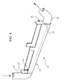
- Figure 4 shows in detail a variation of intermediate bin 9, which may be used to advantage when laundry drier 1 is connected to a second laundry machine, in this case a washing machine (not shown), to form a laundry unit.
- drier 1 in the course of the drying cycle, hot air is fed into the drum (not shown) and over the laundry to dry and evaporate the moisture in the laundry. Since the air flowing out of the drum (not shown) is therefore typically saturated with moisture, drier 1 comprises condensing means (not shown), and a condensate collecting tank (not shown) located inside drier 1.
- Intermediate bin 9 has two openings 19 and 20 formed through two minor lateral walls 21 and 22, and bottom wall 13 slopes downwards and is lowest at opening 20. Part of the condensate produced during the drying cycle is fed by a tube 23 from the tank into intermediate bin 9 through opening 19, and flows out of intermediate bin 9 through opening 20 to flush out the fluff deposited on bottom wall 13.
- the washing machine comprises a wash water drain system, and is connected to laundry drier 1 so that the drying cycle condensate and fluff flowing out of laundry drier 1 through opening 18 are fed into a tube 24 in turn connected to the washing machine drain system.
- This embodiment has no removable drawer 5, in that the fluff is flushed out periodically and automatically at each operating cycle, and therefore need not be removed by the user.
- filter 8 is connected or associated to mechanical means, for example a brush, which ARE adapted to detach fluff from the filter 8.
- the brush is connected to a supporting element and is adapted to wipingly slide upon the lateral walls 10 of filter 8 for periodically detaching fluff.
- Embodiments of laundry drier 1 described above have numerous advantages, by reducing or even totally eliminating intervention by the user to empty the fluff drawer 5.
Abstract
Description
- The present invention relates to a laundry machine with a fluff-removing device.
- More specifically, the present invention relates to a laundry machine comprising a fluff-removing device in turn comprising a filter for catching fluff conveyed by a stream of air; cleaning means connected or associated to, and for detaching fluff from, the filter; and a fluff bin connected to, and for collecting fluff detached from, the filter.
- In known devices of the above type, as described for example in
JP2002113291 DE7117465 , the fluff bin is housed in a seat formed inside the machine and accessible from outside the machine through an opening, is of relatively small capacity, only capable of collecting fluff from one machine operating cycle, and must therefore be emptied by the user after each operating cycle and before starting the next cycle. - Besides being an inconvenience to the user, repeatedly emptying the bin after each cycle also involves awkward manoeuvring on the part of the user in the event the bin is located in a part of the machine that is hard to reach.
- It is an object of the present invention to provide a laundry machine designed to eliminate the above drawbacks.
- According to the present invention, there is provided a laundry machine as claimed in the accompanying Claims.
- A number of non-limiting embodiments of the present invention will be described by way of example with reference to the accompanying drawings, in which:
-
Figure 1 shows a view in perspective of a preferred embodiment of the laundry machine according to the present invention; -
Figure 2 shows a partly exploded view in perspective of a detail inFigure 1 ; -
Figure 3 shows a second embodiment of a detail inFigure 2 . -
Figure 4 shows a third embodiment of a detail inFigure 2 . - In
Figure 1 , numeral 1 indicates as a whole a laundry machine, in the example shown, a front-loading laundry drier. - Laundry drier 1 comprises a
front wall 2; and anopening 3 formed at one end offront wall 2 and communicating with a seat 4 formed in laundry drier 1 to house afluff drawer 5 having afront wall 6 defining a bottom portion offront wall 2 of laundry drier 1.Drawer 5 is accessible and can be removed periodically by the user of laundry drier 1 from seat 4 to remove the fluff collected insidedrawer 5. - To dry the laundry inside a drum (not shown) of laundry drier 1, a stream of hot air is fed into the drum (not shown) and over the laundry. The air flowing out of the drum, after flowing through the laundry, also takes with it a certain amount of fluff detached from the laundry, and which is filtered and collected by a fluff-removing
device 7. - As shown more clearly in
Figure 2 , fluff-removingdevice 7 comprises a fluff filter 8, anintermediate bin 9, andfinal fluff drawer 5 located downstream fromintermediate bin 9 and accessible by the user. - More specifically, filter 8 is pocket-shaped, and the fluff-containing air stream flows over two major
lateral walls 10 designed to trap the fluff in the mesh of filter 8. Filter 8 is associated to cleaning means adapted to detach fluff from the filter 8. In this case, avibrating device 11 is connected to the filter 8 and operated periodically to vibrate majorlateral walls 10 and easily detach the fluff collected on filter 8 to prevent clogging of filter 8. - The fluff vibrated off filter 8 drops by gravity into
intermediate bin 9 located directly below filter 8. More specifically,intermediate bin 9 has anopening 12 having a central portion formed through abottom wall 13, and two lateral portions formed respectively in two majorlateral walls bottom wall 13, and dividesbottom wall 13 into two downward-sloping half-walls 16 which are lowest at opening 12. The fluff detached from filter 8 drops ontobottom wall 13 and slides by gravity along the two sloping half-walls 16 to opening 12 and intodrawer 5.Intermediate bin 9 is also connected to vibratingdevice 11 to vibrate the two half-walls 16 to assist downward flow by gravity to opening 12 of the fluff deposited onbottom wall 13. It is important to note that opening 12 is formed substantially halfway alongbottom wall 13 to minimize the distance travelled by the fluff. - The fluff issuing from
intermediate bin 9 through opening 12 collects by gravity insidedrawer 5, which has a large enough capacity to hold the fluff collected in a number of operating cycles of laundry drier 1. - Moreover, laundry drier 1 provides for a substantial reduction in fluff removal time, by virtue of the fluff being detached from filter 8 and transferred from
intermediate bin 9 todrawer 5 practically simultaneously by vibratingdevice 11. - In a variation not shown,
opening 12 is formed substantially at one end ofbottom wall 13, which slopes downwards and is lowest at opening 12. -
Figures 3 and4 show two different embodiments ofintermediate bin 9, which are similar tointermediate bin 9 inFigure 2 , and the corresponding parts of which are indicated, where possible, using the same reference numbers. - More specifically, as regards
Figure 3 ,intermediate bin 9 has anopening 17 formed through thebottom wall 13, substantially at one end of thebottom wall 13. An Archimedeanscrew 18 is contained within theintermediate bin 9 and is turned by a motor (not shown) so as to deliver fluff to theopening 17. - The fluff detached from filter 8 drops by gravity into the
intermediate bin 9 and is conveyed by the Archimedeanscrew 18 to opening 17; through theopening 17, the fluff collects by gravity insidedrawer 5, which has a large enough capacity to hold the fluff collected in a number of operating cycles of laundry drier 1. -
Figure 4 , instead, shows in detail a variation ofintermediate bin 9, which may be used to advantage when laundry drier 1 is connected to a second laundry machine, in this case a washing machine (not shown), to form a laundry unit. - As regards laundry drier 1, in the course of the drying cycle, hot air is fed into the drum (not shown) and over the laundry to dry and evaporate the moisture in the laundry. Since the air flowing out of the drum (not shown) is therefore typically saturated with moisture, drier 1 comprises condensing means (not shown), and a condensate collecting tank (not shown) located inside drier 1.
-
Intermediate bin 9 has twoopenings lateral walls bottom wall 13 slopes downwards and is lowest at opening 20. Part of the condensate produced during the drying cycle is fed by atube 23 from the tank intointermediate bin 9 through opening 19, and flows out ofintermediate bin 9 through opening 20 to flush out the fluff deposited onbottom wall 13. - The washing machine comprises a wash water drain system, and is connected to laundry drier 1 so that the drying cycle condensate and fluff flowing out of laundry drier 1 through opening 18 are fed into a
tube 24 in turn connected to the washing machine drain system. - This embodiment has no
removable drawer 5, in that the fluff is flushed out periodically and automatically at each operating cycle, and therefore need not be removed by the user. - In a variation not shown, filter 8 is connected or associated to mechanical means, for example a brush, which ARE adapted to detach fluff from the filter 8. The brush is connected to a supporting element and is adapted to wipingly slide upon the
lateral walls 10 of filter 8 for periodically detaching fluff. - Embodiments of laundry drier 1 described above have numerous advantages, by reducing or even totally eliminating intervention by the user to empty the
fluff drawer 5.
Claims (15)
- A laundry machine (1) comprising a fluff-removing device (7); the fluff-removing device (7) comprising:a filter (8) for catching fluff conveyed in a stream of air;cleaning means (11) adapted to detach fluff from the filter (8); anda bin (9) fitted to the filter (8) to collect the fluff detached from the filter (8);the machine (1) being characterized in that the bin (9) has at least one fluff outlet opening (12; 17; 20); and the bin (9) comprising conveying means (13; 18; 11) to assist fluff flow to the outlet opening (12; 17; 20).
- A machine as claimed in Claim 1, wherein the cleaning means comprise mechanical means adapted to wipingly slide upon the filter (8) to detach fluff from the filter (8) itself.
- A machine as claimed in Claim 1, wherein the cleaning means (11) comprise a first vibrating device (11) which is associated to the filter (8) to detach fluff from the filter (8) itself.
- A machine as claimed in Claim 2 or 3, wherein the conveying means (18) comprise a mobile pushing element (18) provided within the intermediate bin (9) to deliver fluff to the opening (17).
- A machine as claimed in Claim 4, wherein the bin (9) has a bottom wall (13), the opening (17) being formed through the bottom wall (13), substantially at one end of the bottom wall (13).
- A machine as claimed in Claim 5, wherein the mobile pushing element (18) is an Archimedean screw (18).
- A machine as claimed in Claim 2 or 3, wherein the conveying means (13) comprise at least one bottom wall (13) which slopes downwards and is lowest at the outlet opening (12) to assist fluff flow to the outlet opening (12).
- A machine as claimed in Claim 7, wherein the conveying means (13) comprise a second vibrating device associated to the bin (9) to assist fluff flow to the outlet opening (12).
- A machine as claimed in Claim 3 and 7, wherein the cleaning means (11) comprise a first vibrating device (11) which is associated to the filter (8) to detach fluff from the filter (8) itself and the conveying means (13; 11) also comprise the first vibrating device (11), which is associated to the bin (9) to assist fluff flow to the outlet opening (12).
- A machine as claimed in Claim 7, 8 or 9, wherein the outlet opening (12) is located halfway along the bottom wall (13); the bottom wall (13) being divided into two half-walls (16), each of which slopes downwards and is lowest at the outlet opening (12).
- A machine as claimed in Claim 7, 8 or 9, wherein the outlet opening (12) is located at one end of the bottom wall (13); and the bottom wall (13) slopes downwards and is lowest at the outlet opening (12).
- A machine as claimed in one of Claims 1 to 9, wherein the fluff-removing device (7) comprises a drawer (5) for collecting the fluff issuing from the bin (9) through the outlet opening (12; 17); and the machine (1) comprises a seat (4) housing the drawer (5) and communicating with the outside through an opening (3) formed in the machine (1) to permit user access to the drawer (5).
- A machine as claimed in Claim 2 or 3, wherein the bin (9) has a first (19) and a second (20) opening located at opposite ends of the bottom wall (13); and the conveying means comprise a stream of water, which is fed into the bin (9) through the first opening (19), and flows out of the bin (9) through the second opening (20) to flush out the fluff deposited on the bottom wall (13).
- A machine as claimed in Claim 13, wherein the conveying means (13) also comprise the bottom wall (13) which slopes downwards from the first opening (19) to the second opening (20).
- A machine as claimed in Claim 14, wherein the machine is a laundry drier (1), and is connected to a laundry washing machine having a laundry wash water drain system; the drier (1) being connected to the washing machine so that the water and fluff issuing from the drier (1) through the second opening (20) are fed into a tube (24) connected to the drain system of the washing machine.
Priority Applications (1)
| Application Number | Priority Date | Filing Date | Title |
|---|---|---|---|
| EP08160353A EP2146000A1 (en) | 2008-07-14 | 2008-07-14 | Laundry machine with a fluff-removing device |
Applications Claiming Priority (1)
| Application Number | Priority Date | Filing Date | Title |
|---|---|---|---|
| EP08160353A EP2146000A1 (en) | 2008-07-14 | 2008-07-14 | Laundry machine with a fluff-removing device |
Publications (1)
| Publication Number | Publication Date |
|---|---|
| EP2146000A1 true EP2146000A1 (en) | 2010-01-20 |
Family
ID=40086408
Family Applications (1)
| Application Number | Title | Priority Date | Filing Date |
|---|---|---|---|
| EP08160353A Withdrawn EP2146000A1 (en) | 2008-07-14 | 2008-07-14 | Laundry machine with a fluff-removing device |
Country Status (1)
| Country | Link |
|---|---|
| EP (1) | EP2146000A1 (en) |
Cited By (10)
| Publication number | Priority date | Publication date | Assignee | Title |
|---|---|---|---|---|
| EP2341182A1 (en) * | 2009-12-29 | 2011-07-06 | Samsung Electronics Co., Ltd. | Filter cleaning device |
| WO2012022642A1 (en) * | 2010-08-20 | 2012-02-23 | BSH Bosch und Siemens Hausgeräte GmbH | Laundry treatment device comprising a lint filter |
| EP2458070A1 (en) * | 2010-10-12 | 2012-05-30 | Samsung Electronics Co., Ltd. | Clothes dryer and lint cleaning device thereof |
| WO2011139092A3 (en) * | 2010-05-07 | 2012-07-19 | Lg Electronics Inc. | Clothes treating apparatus and filter technology |
| EP2567017A2 (en) * | 2010-05-04 | 2013-03-13 | LG Electronics Inc. | Clothes treating apparatus |
| JP2013128531A (en) * | 2011-12-20 | 2013-07-04 | Panasonic Corp | Clothes dryer |
| CN103911801A (en) * | 2012-12-31 | 2014-07-09 | Lg电子株式会社 | Laundry Treatment Apparatus |
| US8869421B2 (en) | 2010-05-04 | 2014-10-28 | Lg Electronics Inc. | Control technology for clothes treatment apparatus |
| DE102014223966A1 (en) * | 2014-11-25 | 2016-05-25 | BSH Hausgeräte GmbH | Filter housing, removable filter unit with such and household appliance with such |
| EP3066254A4 (en) * | 2013-11-05 | 2017-06-21 | Barrett, Kenneth A. | Dryer lint collection system |
Citations (6)
| Publication number | Priority date | Publication date | Assignee | Title |
|---|---|---|---|---|
| DE7117465U (en) | 1971-04-30 | 1972-10-05 | Siemens-Electrogeraete Gmbh | Tumble dryer working according to the drum principle |
| DE8224528U1 (en) * | 1982-08-31 | 1983-02-03 | Licentia Patent-Verwaltungs-Gmbh, 6000 Frankfurt | ELECTRIC LAUNDRY DRYER |
| DE3438575A1 (en) | 1984-10-20 | 1986-04-30 | Herbert Kannegiesser Gmbh + Co, 4973 Vlotho | Appliance for the drying of laundry |
| US4700492A (en) * | 1986-02-05 | 1987-10-20 | Whirlpool Corporation | Air actuated automatic lint screen cleaning system for dryer |
| US5628122A (en) * | 1994-10-05 | 1997-05-13 | Peter And Theordore Spinardi Investments | Lint remover for a clothes drying machine |
| JP2002113291A (en) | 2000-10-10 | 2002-04-16 | Tosen Machinery Corp | Dryer |
-
2008
- 2008-07-14 EP EP08160353A patent/EP2146000A1/en not_active Withdrawn
Patent Citations (6)
| Publication number | Priority date | Publication date | Assignee | Title |
|---|---|---|---|---|
| DE7117465U (en) | 1971-04-30 | 1972-10-05 | Siemens-Electrogeraete Gmbh | Tumble dryer working according to the drum principle |
| DE8224528U1 (en) * | 1982-08-31 | 1983-02-03 | Licentia Patent-Verwaltungs-Gmbh, 6000 Frankfurt | ELECTRIC LAUNDRY DRYER |
| DE3438575A1 (en) | 1984-10-20 | 1986-04-30 | Herbert Kannegiesser Gmbh + Co, 4973 Vlotho | Appliance for the drying of laundry |
| US4700492A (en) * | 1986-02-05 | 1987-10-20 | Whirlpool Corporation | Air actuated automatic lint screen cleaning system for dryer |
| US5628122A (en) * | 1994-10-05 | 1997-05-13 | Peter And Theordore Spinardi Investments | Lint remover for a clothes drying machine |
| JP2002113291A (en) | 2000-10-10 | 2002-04-16 | Tosen Machinery Corp | Dryer |
Cited By (23)
| Publication number | Priority date | Publication date | Assignee | Title |
|---|---|---|---|---|
| EP2341182A1 (en) * | 2009-12-29 | 2011-07-06 | Samsung Electronics Co., Ltd. | Filter cleaning device |
| EP2567017A4 (en) * | 2010-05-04 | 2014-01-15 | Lg Electronics Inc | Clothes treating apparatus |
| EP3584362A1 (en) * | 2010-05-04 | 2019-12-25 | LG Electronics Inc. | Clothes treating apparatus |
| US9096970B2 (en) | 2010-05-04 | 2015-08-04 | Lg Electronics Inc. | Clothes treating apparatus |
| US8869421B2 (en) | 2010-05-04 | 2014-10-28 | Lg Electronics Inc. | Control technology for clothes treatment apparatus |
| EP2567017A2 (en) * | 2010-05-04 | 2013-03-13 | LG Electronics Inc. | Clothes treating apparatus |
| EP2567018A4 (en) * | 2010-05-04 | 2017-12-27 | LG Electronics Inc. | Control technology for clothes treatment apparatus |
| AU2011249152B2 (en) * | 2010-05-07 | 2013-11-07 | Lg Electronics Inc. | Clothes treating apparatus and filter technology |
| US8789287B2 (en) | 2010-05-07 | 2014-07-29 | Lg Electronics Inc. | Clothes treating apparatus and filter technology |
| EP2567016A2 (en) * | 2010-05-07 | 2013-03-13 | LG Electronics Inc. | Clothes treating apparatus and filter technology |
| WO2011139092A3 (en) * | 2010-05-07 | 2012-07-19 | Lg Electronics Inc. | Clothes treating apparatus and filter technology |
| EP2567016A4 (en) * | 2010-05-07 | 2014-01-15 | Lg Electronics Inc | Clothes treating apparatus and filter technology |
| CN102884244A (en) * | 2010-05-07 | 2013-01-16 | Lg电子株式会社 | Clothes treating apparatus and filter technology |
| CN102884244B (en) * | 2010-05-07 | 2015-08-26 | Lg电子株式会社 | Device for clothing processing and filtering technique |
| WO2012022642A1 (en) * | 2010-08-20 | 2012-02-23 | BSH Bosch und Siemens Hausgeräte GmbH | Laundry treatment device comprising a lint filter |
| EP2458070A1 (en) * | 2010-10-12 | 2012-05-30 | Samsung Electronics Co., Ltd. | Clothes dryer and lint cleaning device thereof |
| US8667705B2 (en) | 2010-10-12 | 2014-03-11 | Samsung Electronics Co., Ltd. | Clothes dryer and lint cleaning device thereof |
| JP2013128531A (en) * | 2011-12-20 | 2013-07-04 | Panasonic Corp | Clothes dryer |
| CN103911801B (en) * | 2012-12-31 | 2016-07-06 | Lg电子株式会社 | Device for clothing processing |
| US9316440B2 (en) | 2012-12-31 | 2016-04-19 | Lg Electronics Inc. | Laundry treatment apparatus |
| CN103911801A (en) * | 2012-12-31 | 2014-07-09 | Lg电子株式会社 | Laundry Treatment Apparatus |
| EP3066254A4 (en) * | 2013-11-05 | 2017-06-21 | Barrett, Kenneth A. | Dryer lint collection system |
| DE102014223966A1 (en) * | 2014-11-25 | 2016-05-25 | BSH Hausgeräte GmbH | Filter housing, removable filter unit with such and household appliance with such |
Similar Documents
| Publication | Publication Date | Title |
|---|---|---|
| EP2146000A1 (en) | Laundry machine with a fluff-removing device | |
| CN105937179B (en) | Household ironing appliance comprising a filter for retaining scale particles conveyed by steam | |
| CN103269632B (en) | Table-ware washing machine including storage box | |
| EP3004450B1 (en) | Laundry dryer and method of operating a laundry dryer | |
| US6016610A (en) | Self-cleaning lint trap and gravity assisted lint trap | |
| EP2938776B1 (en) | A laundry dryer comprising a filter | |
| CN108411596B (en) | Iron comprising means for intercepting scale particles conveyed by steam | |
| JP2006225846A (en) | Refuse and oil removing device and refuse and oil collection bag for the device | |
| EP1881101B1 (en) | Domestic washing machine with improved filter | |
| EP1464265A2 (en) | Vacuum cleaner | |
| US20080235978A1 (en) | Self-cleaning lint collector | |
| US6101741A (en) | Gravity assisted lint trap | |
| EP2719819B1 (en) | Heat pump laundry dryer | |
| JP2019150391A (en) | Filtration device for washing machine and washing machine having the same attached thereto | |
| CN112424416B (en) | Washing machine | |
| KR20170004400U (en) | cat's sand collecter | |
| EP1947232B1 (en) | Household clothes drying machine with vibrating lint filter | |
| KR20100026746A (en) | Cyclone dust collecting apparatus for vacuum cleaner and dust separating method | |
| US10426314B2 (en) | Fluid pump volute diversion system, solids collection system and related methods for a washing machine | |
| EP3138952B1 (en) | A laundry dryer | |
| KR20100006488U (en) | An apparatus for dehydrating of a wet umbrella | |
| JP4245611B2 (en) | Filtration distillation apparatus, filter used therefor, and dry cleaning apparatus | |
| KR101918729B1 (en) | Wet type vacuum cleaner | |
| JP3198267U (en) | Grease trap cleaning device | |
| SE521117C2 (en) | Method and apparatus for separating granules from cleaning liquid in a cleaning machine |
Legal Events
| Date | Code | Title | Description |
|---|---|---|---|
| PUAI | Public reference made under article 153(3) epc to a published international application that has entered the european phase |
Free format text: ORIGINAL CODE: 0009012 |
|
| AK | Designated contracting states |
Kind code of ref document: A1 Designated state(s): AT BE BG CH CY CZ DE DK EE ES FI FR GB GR HR HU IE IS IT LI LT LU LV MC MT NL NO PL PT RO SE SI SK TR |
|
| AX | Request for extension of the european patent |
Extension state: AL BA MK RS |
|
| 17P | Request for examination filed |
Effective date: 20100705 |
|
| 17Q | First examination report despatched |
Effective date: 20100730 |
|
| AKX | Designation fees paid |
Designated state(s): AT BE BG CH CY CZ DE DK EE ES FI FR GB GR HR HU IE IS IT LI LT LU LV MC MT NL NO PL PT RO SE SI SK TR |
|
| RAP1 | Party data changed (applicant data changed or rights of an application transferred) |
Owner name: ELECTROLUX HOME PRODUCTS CORPORATION N.V. |
|
| RAP1 | Party data changed (applicant data changed or rights of an application transferred) |
Owner name: ELECTROLUX HOME PRODUCTS CORPORATION N.V. |
|
| STAA | Information on the status of an ep patent application or granted ep patent |
Free format text: STATUS: THE APPLICATION IS DEEMED TO BE WITHDRAWN |
|
| 18D | Application deemed to be withdrawn |
Effective date: 20150203 |