EP2145737B1 - A fastener drive device, a trigger assembly and a method of selecting a mode of operation of a fastener driving device - Google Patents
A fastener drive device, a trigger assembly and a method of selecting a mode of operation of a fastener driving device Download PDFInfo
- Publication number
- EP2145737B1 EP2145737B1 EP09165811A EP09165811A EP2145737B1 EP 2145737 B1 EP2145737 B1 EP 2145737B1 EP 09165811 A EP09165811 A EP 09165811A EP 09165811 A EP09165811 A EP 09165811A EP 2145737 B1 EP2145737 B1 EP 2145737B1
- Authority
- EP
- European Patent Office
- Prior art keywords
- trigger
- mode
- driving device
- fastener driving
- mode selector
- Prior art date
- Legal status (The legal status is an assumption and is not a legal conclusion. Google has not performed a legal analysis and makes no representation as to the accuracy of the status listed.)
- Active
Links
Images






Classifications
-
- B—PERFORMING OPERATIONS; TRANSPORTING
- B25—HAND TOOLS; PORTABLE POWER-DRIVEN TOOLS; MANIPULATORS
- B25C—HAND-HELD NAILING OR STAPLING TOOLS; MANUALLY OPERATED PORTABLE STAPLING TOOLS
- B25C1/00—Hand-held nailing tools; Nail feeding devices
- B25C1/008—Safety devices
-
- B—PERFORMING OPERATIONS; TRANSPORTING
- B25—HAND TOOLS; PORTABLE POWER-DRIVEN TOOLS; MANIPULATORS
- B25C—HAND-HELD NAILING OR STAPLING TOOLS; MANUALLY OPERATED PORTABLE STAPLING TOOLS
- B25C1/00—Hand-held nailing tools; Nail feeding devices
- B25C1/04—Hand-held nailing tools; Nail feeding devices operated by fluid pressure, e.g. by air pressure
- B25C1/041—Hand-held nailing tools; Nail feeding devices operated by fluid pressure, e.g. by air pressure with fixed main cylinder
- B25C1/043—Trigger valve and trigger mechanism
Definitions
- the present invention relates to a fastener driving device, a trigger assembly and a method of selecting a mode of operation of a fastener driving device.
- this invention relates to fastener driving devices and, more particularly, to fastener driving devices having a mode selector and trigger lock and a method of selecting mode of operation.
- Fastener driving tools for driving fasteners such as nails, staples or the like are commonly used in industry and commerce.
- the fasteners are generally supplied from a collated strip of fasteners disposed in a magazine coupled to a nosepiece portion of the fastener driving tool.
- the fastener driving tool also comprises a housing to store compressed air, a cylinder within the housing, a piston within the cylinder, a driver connected to the piston, and a main valve to provide pressurized air to operate the piston.
- Fastener driving tools also include a work contacting element coupled to a tool controlling mechanism operable as a safety feature to enable and disable the fastener driving tool. In some instances, this work contacting element is coupled with a depth adjusting mechanism that allows control and adjustment of the depth at which the fastener is driven into a work piece.
- the tool is positioned in contact with a workpiece, such as wood or drywall, in such a manner as to allow the contacting element or the depth adjusting mechanism to be in direct contact with the work piece.
- the trigger is manually pulled to actuate a trigger valve which in turn operates the main valve that provides compressed air to move the piston.
- the trigger can also be made to be remotely controllable if desired.
- US2001/0006183 discloses a fastener driving tool including a fastener driving mechanism and a trigger assembly, according to the preamble to claim 1, that is movable from an OFF position to an ON position for actuating the fastener drive mechanism.
- a mode change device is operable to selectively change a tool mode among a first drive mode, a second drive mode and a drive inhibit mode for the fastener drive mechanism.
- the mode change device includes an operation member that is operable by an operator. The operation member has a plurality of operational positions that correspond to the changeable modes.
- a trigger assembly according to claim 1.
- the mode selector is rotatably mounted to the frame.
- the trigger assembly further comprises a rocker rotatably mounted to the trigger lever.
- the rocker is biased toward the trigger lever by a resilient membere.
- the trigger assembly further comprises a linkage member rotatably linked to the rocker and to the trigger lever.
- the trigger assembly further comprises a cam shaft and a first extremity of the linkage member and a first extremity of the rocker are mounted to the cam shaft, the cam shaft being movably mounted to the trigger lever.
- the mode selector comprises an eccentric pin and a knob, wherein a second extremity of the linkage member is connected to the eccentric pin and a second extremity of the rocker is free to move.
- the fastener drive device further comprises a contact trip assembly operatively disposed within a nosepiece of fastener driving device, wherein the second extremity of the rocker extends to a position near a top of the contact trip assembly.
- the knob is rotatable to switch between a sequential mode of operation of the fastener driving device and a bump mode of operation of the fastener driving device.
- a rotation of the knob results in a translation of the first extremity of the linkage member and a displacement of the second extremity of the rocker relative to the contact arm.
- the second extremity of the rocker moves at a forward position within a path of the contact trip assembly, and when the knob is in a second position corresponding to the sequential mode of operation, the second extremity of the rocker moves away from the path of the contact trip assembly.
- the trigger lock comprises a trigger lock handle, wherein the knob comprises a pair of notches configured to receive the trigger lock handle when the trigger lock is in the first position.
- moving the trigger lock in the first direction comprises pushing a trigger lock pin handle inwardly towards a frame of the fastener driving device.
- moving the mode selector switch to the desired mode of operation of the fastener driving device comprises rotating the mode selector 180 degrees to a first position for operating the fastener driving device in sequential mode or to a second position for operating the fastener driving device in bump mode.
- moving the trigger lock in the second direction comprises pushing a trigger lock pin button towards a frame of the fastener driving device so as to move a trigger lock pin handle outwardly away from the frame.
- moving the trigger lock in the first direction comprises pushing a trigger lock pin handle inwardly towards the frame of the fastener driving device.
- moving the mode selector switch to the desired mode of operation of the fastener driving device comprises rotating the mode selector 180 degrees to a first position for operating the fastener driving device in a sequential mode or to a second position for operating the fastener driving device in a bump mode.
- moving the trigger lock in the second direction comprises pushing a trigger lock pin button towards the frame of the fastener driving device so as to move a trigger lock pin handle outwardly away from the frame.
- a fastener driving device configured to be mounted to the fastener driving device, the trigger lock being movable between a first position wherein movement of the trigger lever to the actuated position is permitted and a second position wherein movement of the trigger lever to the actuation position is prevented, wherein, in the first position, the trigger lock engages the mode selector to prevent the mode selector from moving, wherein, in the second position, the trigger lock disengages the mode selector to permit movement of the mode selector to select the mode of operation of the fastener driving device.
- a fastener driving device comprises a frame, a fastener driver reciprocally mounted in the frame, and a trigger assembly.
- the trigger assembly comprises a trigger lever configured to be moved to an actuated position to actuate the fastener driving device, a mode selector movably mounted to the frame, the mode selector being configured to move to select a mode of operation of the fastener driving device, and a trigger lock mounted to the frame, the trigger lock being movable between a first position wherein actuation of the trigger lever is permitted and a second position wherein actuation of the trigger lever is prevented.
- the trigger lock engages the mode selector to prevent the mode selector from moving.
- the trigger lock disengages the mode selector to permit movement of the mode selector to select the mode of operation of the fastener driving device.
- a method of selecting a mode of operation of a fastener driving device comprises moving a trigger lock in a first direction to lock the trigger and release an engagement of the trigger lock with the mode selector switch; moving the mode selector switch to a desired mode of operation of the fastener driving device; and moving the trigger lock in a second direction opposite to the first direction to unlock the trigger and lock the mode selector switch.
- Yet another embodiment method of selecting a mode of operation of a fastener driving device comprises moving a trigger lock in a first direction to lock the trigger; moving the mode selector switch by applying a counteracting force to counteract a biasing force biasing the mode selector switch towards a frame of the fastener driving device so as to release an engagement of the trigger lock with the mode selector switch; moving the mode selector switch to a desired mode of operation of the fastener driving device; releasing the counteracting force applied to the mode selector switch; and moving the trigger lock in a second direction opposite to the first direction to unlock the trigger and lock the mode selector switch.
- a further embodiment comprises a trigger assembly for a fastener driving device
- the trigger assembly includes a trigger lever configured to be moved to an actuated position, a mode selector configured to be movably mounted to the fastener driving device, the mode selector being configured to move to select a mode of operation of the fastener driving device, and a trigger lock configured to be mounted to the fastener driving device.
- the trigger lock is movable between a first position wherein movement of the trigger lever to the actuated position is permitted and a second position wherein movement of the trigger lever to the actuation position is prevented. In the first position, the trigger lock engages the mode selector to prevent the mode selector from moving. In the second position, the trigger lock disengages the mode selector to permit movement of the mode selector to select the mode of operation of the fastener driving device.
- FIG. 1 illustrates a fastener driving device 10, according to an embodiment of the present invention.
- the device 10 includes a housing 12.
- the housing 12 is preferably constructed from a lightweight yet durable material, such as magnesium.
- the housing 12 includes a cylinder containing body portion 14, a handle portion 16, and a cap portion 18.
- the size and shape of these components can vary considerably depending on the type of fastener and application, but all have in common an internal air chamber 20 for containing compressed air, for example, from an external source.
- the compressed air chamber 20 is pressurized from an air supply line through an inlet 21 provided in the handle 16.
- the cap 18 is attached to the body portion 14 with screws (not shown). Part of the volume in cap 18 is used to enlarge the volume of the compressed air chamber 20.
- the lower portion of the housing 12 is connected to a fastener carrying rail or magazine 28.
- the front of the magazine 28 is joined with nosepiece 30, which is provided with a fastener drive track 32.
- a fastener pusher within the magazine 28 (not shown) delivers the fastener into the drive track 32 underneath the end of a fastener striker or driver 33.
- the driver 33 is fixed to the piston 26 and function together as a unit.
- a cylinder 34 is mounted in the housing 12.
- the piston 26 reciprocates in cylinder 34 during operation.
- a trigger valve 36 positioned near the handle 16 and a main valve 38 are employed.
- the trigger valve includes a valve stem 37 that is movable when a force is applied on trigger 39, i.e., when the trigger 39 is rotated toward the valve stem 37.
- a contact trip assembly 46 is mounted so as to have a forward end extend outwardly of the nosepiece 30 to be actuated when the device 10 is moved into operative engagement with a workpiece.
- the contact trip assembly 46 includes a portion which is co-operable with the trigger 39 such that movement of the trigger lever is totally prevented until the contact trip engages the workpiece. As a result, the device 10 is prevented from being actuated until the contact trip assembly 46 is engaged with the workpiece.
- the contact trip assembly 46 is configured to cooperate with the trigger 39 so as to allow a sequential drive of a fastener into the workpiece or a bump drive of a fastener into the workpiece.
- a sequential drive mode or sequential trip (ST) mode the contact trip assembly 46 is brought in contact with a workpiece and the trigger 39 is actuated to drive a fastener and the trigger is released to repeat the fastener driving operation.
- a bump drive mode or contact trip (CT) mode the trigger 39 is actuated and the fastener is driven into a workpiece by "bumping" the contact trip assembly 46 onto the workpiece. This drive operation can be repeated without having to release the trigger 39.
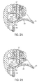
- FIGS. 2A and 2B are cross-sectional views of the trigger or trigger assembly, according to an embodiment of the present invention.
- the trigger or trigger assembly 39 includes a rocker 50 and a trigger lever 51.
- the rocker 50 is biased towards the trigger lever 51 by resilient member (e.g., coil spring) 52.
- resilient member e.g., coil spring
- valve stem 37 is raised when contacted by rocker 50 of the trigger 39 to initiate a drive stroke.
- FIG. 2A shows a position of an extremity 46A of the contact trip 46 relative to a rocker 50 of the trigger 39 where the rocker 50 is in the path of the contact trip 46 when the trigger lever 51 is pulled. In this position, the rocker 50 can be moved by actuating the contract trip assembly 46.
- the device 10 can operate in bump drive mode or contact trip mode.
- FIG. 2B shows a position of the extremity 46A of the contact trip 46 relative to the rocker 50 where the rocker 50 is out of the path of the contact trip 46 when the trigger lever 51 is pulled. In this position, the rocker 50 cannot be moved by actuating the contact trip assembly 46. In this configuration, the device 10 can operate in a sequential drive mode.
- FIG. 3 is an elevational external view of a portion of the device 10 showing the mode selector 60, according to one embodiment of the present invention.
- the mode selector 60 is disposed in the vicinity of the trigger 39.
- the mode selector 60 is movable to one of two positions. One position is indicated on the device 10 by the symbol 62A, which depicts one fastener, for selecting a sequential mode operation and another position is indicated on the device 10 by the symbol 62B, which depicts a plurality of fasteners, for selecting a bump mode operation.
- the device 10 also includes a trigger lock 64.
- the trigger lock 64 operatively engages the mode selector 60.
- the trigger lock 64 can be switched between a locked position to prevent movement of the trigger lever 51 and an unlocked position to permit movement of the trigger lever 51.
- the trigger lock 64 can be switched from a locked to unlocked position by pushing the trigger lock 64 from one side of the device to an opposite side of the device 10, as will be described further in detail in the following paragraphs.
- the unlocked position the trigger lock 64 engages the mode selector 60 to prevent the mode selector 60 from moving, i.e. rotating.
- the trigger lock 64 disengages from the mode selector 60 so as to permit rotation of mode selector 60, for example to select a desired operational mode of the device 10.
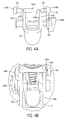
- FIGS. 4A and 5A are elevational views showing the relative positions of the trigger lever 51, the mode selector 60 and the trigger lock 64, according to an embodiment of the present invention.
- FIGS. 4B and 5B are elevational views showing the position of the trigger lever 51, the mode selector 60, and the trigger lock 64 relative to the body of housing 12 of the device 10.
- the trigger lock 64 comprises trigger lock pin 64A, trigger lock handle 64B and trigger lock button 64C.
- the trigger lock pin 64A extends through two frame walls 12A, 12B of the housing 12.
- the trigger lock handle 64B is mounted to one end of the trigger lock pin 64A and is disposed adjacent wall 12A in the vicinity and operatively engaging the mode selector 60.
- the trigger lock button 64C is mounted to an opposite end of the trigger lock pin 64A adjacent opposite frame wall 12B. As shown in FIGS. 4A and 5A , the trigger lock pin 64A has two notches 64D.
- the trigger lock pin handle 64B When the trigger lock pin handle 64B is pushed inwardly towards the frame wall 12A into a locked position, as shown in FIG. 4B , the trigger lock pin 64A interferes and prevents movement of the trigger lever 51 from a down-unactuated position to an up-actuated position.
- the notches 64D in the trigger lock pin 64A are positioned such that adjacent two portions 51A and 51B of the trigger lever 51 are not aligned with the notches 64D and abut on the trigger lock pin 64A hence preventing movement of the trigger lever 51.
- the trigger lock pin handle 64B When the trigger lock button 64C is pushed inwardly towards the frame wall 12B, the trigger lock pin handle 64B is pushed outwardly away from the frame wall 12A into an unlocked position, as shown in FIG. 5B . In this position, the notches 64D in the trigger lock pin 64A align with the two portions 51A and 51B of the trigger lever 51, as shown in FIG. 5A , hence allowing movement of the trigger lever 51.
- the trigger lock pin 64A may be held in the locked and unlocked positions by O-rings 65 mounted on each end of the trigger lock pin 64A for creating a friction fit with apertures formed in the tool frame walls 12A and 12B through which the pin extends.
- the trigger lock button 64C may include a flat edge engaging a land formed on the tool frame wall 12B to prevent the trigger lock pin 64A from rotating.
- the openings or notches 64D in the trigger lock pin 64A are sized and positioned relative to the portions 51A and 51B of the trigger body so that the trigger body portions 51A and 51B move out of the openings 64D only when the trigger lever 51 is all the way down (away from the valve stem 37) in the unactuated position. This ensures that the mode selector 60 can only be adjusted/rotated when the trigger lever 51 is all the way down by permitting movement of the trigger lock pin 64A transversely. If the trigger lock 64 is pushed while the trigger lever 51 is not fully down, the trigger body portions 51A and 51B being inside the notches or openings 64D will prevent movement of the trigger lock pin 64A.
- FIG. 6 is an exploded view of the trigger assembly 39 including the trigger lever 51, trigger lock 64 and mode selector 60, according to an embodiment of the present invention.
- the mode selector 60 comprises an eccentric pin 60A and a knob 60B.
- the eccentric pin 60A is mounted to the trigger lever 51 through an opening or hole 51C in the trigger lever 51.
- One end 60A1 of the eccentric pin 60A is connected to the knob 60B via a cylindrical piece 60D having an eccentric opening 60D1.
- the cylindrical piece 60D is adapted and sized to rotatably fit in hole 51C in the trigger lever 51.
- An opposite end 60A2 of eccentric pin 60A is provided with a stop portion that is adapted to abut against body portion 51A of the trigger lever 51 when the eccentric pin 60A is mounted through the opening 51C.
- FIG. 7 is a perspective view of the trigger assembly 39 including the trigger lever 51, mode selector 60, rocker 50 and linkage member 54, according to an embodiment of the present invention.
- one end 54A of linkage member 54 is rotatably linked to extremity 50A of the rocker 50.
- Both the end 54A of the linkage member 54 and the extremity 50A of the rocker 50 are rotatably mounted to body portions 51A and 51B of the trigger lever 51 via a cam shaft 55.
- the cam shaft 55 is movably mounted to the body portions 51A and 51B of the trigger lever 51 through slots 51D.
- the cam shaft 55 can both rotate and translate within the slots 51D.
- the slots 51D are positioned in the body portions 51A and 51B of the trigger lever 51 so as to allow the linkage member 54 and the rocker 50 to move.
- a resilient member 60E is provided axially within the eccentric pin 60A.
- the resilient member 60E abuts against stop portion 60A2 of the eccentric pin 60A on one end and on the opposite end abuts against end portion 54B of the linkage member 54.
- the resilient member 60E biases the knob 60B mounted to the end 60A1 of the eccentric pin 60A towards the body portion 51 B of the trigger lever 51.
- the end 50B of the rocker 50 extends to a position near a top of the contact trip assembly 46 (as shown in FIGS. 2A and 2B ).
- This position of the rocker is changed/moved to switch between sequential and bump modes by rotating the knob 60B of the mode selector switch 60.
- a rotation of the knob 60B of the mode selector switch 60 causes the eccentric pin 60A to rotate.
- the pin 60A is eccentric relative to axis AA of rotation of the knob 60B
- a rotation of the eccentric pin 60A results in a translation of the end 54A of the linkage member 54 and hence of a displacement of the end 50A of the rocker 50 and ultimately in a position change of the end 50B of the rocker 50 relative to the contact trip assembly 46 (shown in FIGS. 2A and 2B ).
- the pivot point of the trigger lever 51 does not move.
- the knob 60B of the mode selector switch 60 has a pair of notches 60B1 and 60B2.
- the notches 60B1 and 60B2 are configured to receive the trigger lock pin handle 64B of the trigger lock pin 64 when the trigger lock pin 64 is in an unlocked position. In this position, the engagement of the trigger lock pin handle 64B with the knob 60B prevents rotation of the mode selector switch 60.
- the mode selector switch 60 is configured such that it cannot be inadvertently rotated since the trigger lock pin handle 64B must be pushed into the locked position out of engagement with the mode selector switch knob 60B in order to rotate the knob 60B.
- a raised boss may be formed on the outer frame body 12A (see FIGS. 4B and 5B ).
- the fastener device 10 is configured so as to prevent operation with the mode selector switch 60 in an intermediate position, i.e., where the knob 60B is rotated to a position other than a position indicated by the marks 62A and 62B (see FIG. 3 ) corresponding to the ST and CT mode positions. Indeed, in order to move the mode selector switch knob 60B into an intermediate position, the trigger lock pin 64 must be pushed to disengage from the mode selector switch knob 60B.
- disengaging the trigger lock pin 60 i.e., disengaging the handle 64B
- disengaging the handle 64B from the selector switch knob 60B also causes the trigger lock pin 60 to lock the trigger 39 in the de-actuated position by blocking the movement of the trigger lever 51 by shifting the notches 64D in the trigger lock pin 60 from the trajectory of the trigger lever frame portions 51A and 51B.
- interlock assembly is described herein as being used in a pneumatic type fastener driving device, as it can be appreciated the interlock assembly may be used on any fastener driving tool, such as a nail or staple gun, having a trigger and a mode selector switch.
- the fastener driving tool may be operated/powered by any means such as pneumatic, spring, pressurized gas, combustion, flywheel, electric motor, and any combination of these.
- FIG. 8 is a cross-sectional view of the trigger assembly 39 showing the position of the rocker 50 relative to an end of the contact trip 46, according to an embodiment of the present invention.
- the trigger lever 51 is shown actuated or pulled before actuating the contact trip 46 by placing the device 10 against a workpiece.
- the linkage member 54 will be moved by the eccentric pin 60A of the mode selector switch 60, as discussed in the above paragraphs.
- the rocker 50 will correspondingly be moved into or away from the path of the contact trip 46.
- the rocker 50 is positioned at a forward position (the rocker with a solid line).
- the rocker 50 is in the path of the contact trip 46.
- the contact trip 46 will move, i.e., rotate, the rocker 50 upwardly which in turn presses on valve stem 37 to initiate a drive stroke.
- the rocker 50 is positioned at backward position (the rocker with a dotted line). In this position, the rocker 50 is not in the path of the contact trip 46.
- the contact trip 46 will not move the rocker 50 and as a result the device 10 will not be actuated.
- FIG. 9 is a cross-sectional view of the trigger assembly 39 showing the position of the rocker 50 relative to the contact trip 46, according to an embodiment of the present invention.
- the device 10 is first placed against the workpiece.
- the solid line rocker 50 and the dotted line rocker 50 in FIG. 9 indicate the position of the rocker 50 when the mode selector switch is rotated to either contact mode or sequential mode, respectively.
- the rocker 50 In contact mode, the rocker 50 has a greater extension over a thickness of the contact trip 46, i.e., path of the contact trip 46. While in sequential mode, the excursion of the rocker 50 into the path of the contact trip 46 (indicated in dotted lines in FIG. 9 ) is smaller.
- FIG. 10 is a cross-sectional view of the trigger assembly showing the trajectory of the tip of the rocker 50 relative to the tip of the contact trip 46, according to an embodiment of the present invention.
- FIG. 10 shows the trigger lever 51 actuated after the device 10 is placed against the workpiece.
- the solid circle C shows the trajectory of the tip of the rocker 50 when the device 10 is operated in contact mode and the dotted circle C' shows the trajectory of the tip of the rocker 50 when the device 10 is operated in sequential mode.
- the solid circle trajectory C of the tip of the rocker 50 shows that the rocker 50 will always remain above the contact trip 46 before and after actuation of the trigger lever 51.
- the device 10 can be actuated and re-set and re-activated again.
- the circle C' trajectory shows that the tip of the rocker 50 will slip off the path of the contact trip 46 after the tip of the contact trip 46 drops below a certain threshold (e.g., about 5 mm from the full extension of the tip of contact trip 46).
- a certain threshold e.g., about 5 mm from the full extension of the tip of contact trip 46.
- the device can only be actuated by sequentially placing the device 10 against the workpiece to actuate the contact trip 46 and then actuating the trigger lever 51. If the trigger lever 51 is actuated before placing the device 10 against the workpiece, the device 10 will not be actuated.
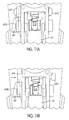
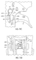
- FIGS. 11A-11D depict a sequence for selecting the mode of operation of the device (i.e., for switching from a sequential mode to a contact trip mode or vice versa), according to an embodiment of the present invention.
- the selection can be accomplished in a three-step process.
- FIG. 11A when the trigger lock 64 is in the unlocked position, the trigger lever 51 is not locked. However, the selector switch 60 is locked as the trigger lock pin handle 64B engages notch 60B 1 or notch 60B2 of the mode selector switch 60.
- the trigger lock pin handle 64B is pushed against the frame of the device 10, in a first step, as indicated by the arrow in FIG.
- the trigger lever 51 is locked and cannot be actuated (as explained in the above paragraphs).
- the selector switch 60 is free to rotate as the trigger lock pin handle 64B is released from the notch 60B1 or 60B2 of the mode selector switch 60.
- the mode selector switch can then be rotated (e.g., for example one half turn counter-clockwise) to the desired mode, as indicated in FIG. 11C .
- the trigger lock button 64C of the trigger lock 64 can then be pushed in the direction of the arrow as indicated in FIG. 11D .
- the selector switch 60 is no longer free to rotate as the trigger lock handle 64B engages the notch 60B1 or 60B1 in the mode selector knob 60B.
- the trigger lever 51 is not locked. Hence, the device 10 can be actuated.
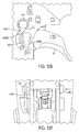
- FIGS. 12A-12F depict a sequence for selecting the mode of operation of the device (i.e., for switching from a sequential mode to a contact trip mode or vice versa), according to another embodiment of the present invention.
- the selection can be accomplished in a four-step process.
- the four-step process is similar to the three-step process described above except that an additional step is required between the first and second steps of the three-step process.
- the trigger lock 60 is pushed against the frame of the device 10
- in a first step as indicated by the arrow in FIG. 12A
- the trigger lever 51 is locked and cannot be actuated.
- the selector switch 60 is not yet free to rotate as the trigger lock pin handle 64B remains engaged with the notch 60B1 or 60B2 of the mode selector switch 60.
- a second step in order to allow the mode selector switch 60 to be rotated (e.g., for example one half turn counter-clockwise) to the desired selection mode, as indicated in FIG. 12B , because the selector switch 60 is biased by the spring 60E (shown in FIG. 6 ) to automatically push the knob 60B of the selector switch 60 towards the frame of the device 10, as shown by the arrow in FIG. 12C , the stop end 60A2 of the eccentric pin 60A of the selector switch 60 should be pushed opposite to the arrow in FIG.
- the mode selector switch 60 can then be rotated (e.g., one half turn counter-clockwise) to the desired selection mode, as indicated in FIG. 12E .
- the user can then release the counteracting force applied to the end stop 60A2.
- the mode selector switch 60 Once the mode selector switch 60 is positioned at the desired mode (sequential mode or contact/bump mode) and the user releases the force applied to the end stop 60A2, the mode selector switch 60 moves automatically towards the frame due to the biasing spring force when either notch 60B1 or 60B2 is aligned with the arm 64B.
- the trigger lock button 64C of the trigger lock 64 can then be pushed in the direction of the arrow, as indicated in FIG. 12F .
- the selector switch 60 is no longer free to rotate.
- the trigger lever 51 is not locked.
- the device 10 can be actuated.
Landscapes
- Engineering & Computer Science (AREA)
- Mechanical Engineering (AREA)
- Physics & Mathematics (AREA)
- Fluid Mechanics (AREA)
- Portable Nailing Machines And Staplers (AREA)
Description
- The present invention relates to a fastener driving device, a trigger assembly and a method of selecting a mode of operation of a fastener driving device.
- In embodiments, this invention relates to fastener driving devices and, more particularly, to fastener driving devices having a mode selector and trigger lock and a method of selecting mode of operation.
- Fastener driving tools for driving fasteners such as nails, staples or the like are commonly used in industry and commerce. The fasteners are generally supplied from a collated strip of fasteners disposed in a magazine coupled to a nosepiece portion of the fastener driving tool. The fastener driving tool also comprises a housing to store compressed air, a cylinder within the housing, a piston within the cylinder, a driver connected to the piston, and a main valve to provide pressurized air to operate the piston. Fastener driving tools also include a work contacting element coupled to a tool controlling mechanism operable as a safety feature to enable and disable the fastener driving tool. In some instances, this work contacting element is coupled with a depth adjusting mechanism that allows control and adjustment of the depth at which the fastener is driven into a work piece.
- During operation of such tools, the tool is positioned in contact with a workpiece, such as wood or drywall, in such a manner as to allow the contacting element or the depth adjusting mechanism to be in direct contact with the work piece. The trigger is manually pulled to actuate a trigger valve which in turn operates the main valve that provides compressed air to move the piston. The trigger can also be made to be remotely controllable if desired.
-
US2001/0006183 discloses a fastener driving tool including a fastener driving mechanism and a trigger assembly, according to the preamble to claim 1, that is movable from an OFF position to an ON position for actuating the fastener drive mechanism. A mode change device is operable to selectively change a tool mode among a first drive mode, a second drive mode and a drive inhibit mode for the fastener drive mechanism. The mode change device includes an operation member that is operable by an operator. The operation member has a plurality of operational positions that correspond to the changeable modes. - According to a first aspect of the present invention, there is provided a trigger assembly according to claim 1.
- Preferably, the mode selector is rotatably mounted to the frame.
- Preferably, the trigger assembly further comprises a rocker rotatably mounted to the trigger lever.
- Preferably, the rocker is biased toward the trigger lever by a resilient membere.
- Preferably, the trigger assembly further comprises a linkage member rotatably linked to the rocker and to the trigger lever.
- Preferably, the trigger assembly further comprises a cam shaft and a first extremity of the linkage member and a first extremity of the rocker are mounted to the cam shaft, the cam shaft being movably mounted to the trigger lever.
- Preferably, the mode selector comprises an eccentric pin and a knob, wherein a second extremity of the linkage member is connected to the eccentric pin and a second extremity of the rocker is free to move.
- Preferably, the fastener drive device further comprises a contact trip assembly operatively disposed within a nosepiece of fastener driving device, wherein the second extremity of the rocker extends to a position near a top of the contact trip assembly.
- Preferably, the knob is rotatable to switch between a sequential mode of operation of the fastener driving device and a bump mode of operation of the fastener driving device.
- Preferably, a rotation of the knob results in a translation of the first extremity of the linkage member and a displacement of the second extremity of the rocker relative to the contact arm.
- Preferably, when the knob is in a first position corresponding to the bump mode of operation, the second extremity of the rocker moves at a forward position within a path of the contact trip assembly, and when the knob is in a second position corresponding to the sequential mode of operation, the second extremity of the rocker moves away from the path of the contact trip assembly.
- Preferably, the trigger lock comprises a trigger lock handle, wherein the knob comprises a pair of notches configured to receive the trigger lock handle when the trigger lock is in the first position.
- According to a second aspect of the present invention, there is provided a method of selecting a mode of operation of a fastener driving device according to
claim 10. - Preferably, moving the trigger lock in the first direction comprises pushing a trigger lock pin handle inwardly towards a frame of the fastener driving device.
- Preferably, moving the mode selector switch to the desired mode of operation of the fastener driving device comprises rotating the mode selector 180 degrees to a first position for operating the fastener driving device in sequential mode or to a second position for operating the fastener driving device in bump mode.
- Preferably, moving the trigger lock in the second direction comprises pushing a trigger lock pin button towards a frame of the fastener driving device so as to move a trigger lock pin handle outwardly away from the frame.
- Preferably, moving the trigger lock in the first direction comprises pushing a trigger lock pin handle inwardly towards the frame of the fastener driving device.
- Preferably, moving the mode selector switch to the desired mode of operation of the fastener driving device comprises rotating the mode selector 180 degrees to a first position for operating the fastener driving device in a sequential mode or to a second position for operating the fastener driving device in a bump mode.
- Preferably, moving the trigger lock in the second direction comprises pushing a trigger lock pin button towards the frame of the fastener driving device so as to move a trigger lock pin handle outwardly away from the frame.
- According to a third aspect of the present invention, there is provided a fastener driving device according to claim 15 configured to be mounted to the fastener driving device, the trigger lock being movable between a first position wherein movement of the trigger lever to the actuated position is permitted and a second position wherein movement of the trigger lever to the actuation position is prevented, wherein, in the first position, the trigger lock engages the mode selector to prevent the mode selector from moving, wherein, in the second position, the trigger lock disengages the mode selector to permit movement of the mode selector to select the mode of operation of the fastener driving device.
- Features expressed herein as being "preferable" may be provided in combination with any of the aspects of the invention either alone or together with other of such features.
- In one embodiment a fastener driving device comprises a frame, a fastener driver reciprocally mounted in the frame, and a trigger assembly. The trigger assembly comprises a trigger lever configured to be moved to an actuated position to actuate the fastener driving device, a mode selector movably mounted to the frame, the mode selector being configured to move to select a mode of operation of the fastener driving device, and a trigger lock mounted to the frame, the trigger lock being movable between a first position wherein actuation of the trigger lever is permitted and a second position wherein actuation of the trigger lever is prevented. In the first position, the trigger lock engages the mode selector to prevent the mode selector from moving. In the second position, the trigger lock disengages the mode selector to permit movement of the mode selector to select the mode of operation of the fastener driving device.
- In one embodiment a method of selecting a mode of operation of a fastener driving device comprises moving a trigger lock in a first direction to lock the trigger and release an engagement of the trigger lock with the mode selector switch; moving the mode selector switch to a desired mode of operation of the fastener driving device; and moving the trigger lock in a second direction opposite to the first direction to unlock the trigger and lock the mode selector switch.
- Yet another embodiment method of selecting a mode of operation of a fastener driving device comprises moving a trigger lock in a first direction to lock the trigger; moving the mode selector switch by applying a counteracting force to counteract a biasing force biasing the mode selector switch towards a frame of the fastener driving device so as to release an engagement of the trigger lock with the mode selector switch; moving the mode selector switch to a desired mode of operation of the fastener driving device; releasing the counteracting force applied to the mode selector switch; and moving the trigger lock in a second direction opposite to the first direction to unlock the trigger and lock the mode selector switch.
- A further embodiment comprises a trigger assembly for a fastener driving device, the trigger assembly includes a trigger lever configured to be moved to an actuated position, a mode selector configured to be movably mounted to the fastener driving device, the mode selector being configured to move to select a mode of operation of the fastener driving device, and a trigger lock configured to be mounted to the fastener driving device. The trigger lock is movable between a first position wherein movement of the trigger lever to the actuated position is permitted and a second position wherein movement of the trigger lever to the actuation position is prevented. In the first position, the trigger lock engages the mode selector to prevent the mode selector from moving. In the second position, the trigger lock disengages the mode selector to permit movement of the mode selector to select the mode of operation of the fastener driving device.
- Other aspects of the present invention are to provide a device of the type describe above which is combined with other features hereafter described in detail.
- These and other aspects of the present invention, as well as the methods of operation and functions of the related elements of structure and the combination of parts and economies of manufacture, will become more apparent upon consideration of the following description and the appended claims with reference to the accompanying drawings, all of which form a part of this specification, wherein like reference numerals designate corresponding parts in the various figures. In one embodiment of the invention, the structural components illustrated herein are drawn to scale. It is to be expressly understood, however, that the drawings are for the purpose of illustration and description only and are not a limitation of the invention. In addition, it should be appreciated that structural features shown or described in any one embodiment herein can be used in other embodiments as well. As used in the specification and in the claims, the singular form of "a", "an", and "the" include plural referents unless the context clearly dictates otherwise.
- Features of the invention are shown in the drawings, in which like reference numerals designate like elements. The drawings form part of this original disclosure. Examples of embodiments of the present invention will now be described in detail with reference to the accompanying drawings, in which:
-
FIG. 1 is a sectional view of the fastener driving device, according to an embodiment of the present invention; -
FIGS. 2A and 2B are cross-sectional views of a trigger assembly, according to an embodiment of the present invention; -
FIG. 3 is an elevational external view of a portion of the fastener driving depicted inFIG. 1 showing a mode selector, according to an embodiment of the present invention; -
FIGS. 4A and 4B are elevational views showing the relative positions of a trigger lever, the mode selector, and a trigger lock when the trigger lock is in a locked position, according to an embodiment of the present invention; -
FIGS. 5A and 5B are elevational views showing the relative positions of the trigger lever, the mode selector, and the trigger lock when the trigger lock is in an unlocked position, according to an embodiment of the present invention; -
FIG. 6 is an exploded view of the trigger assembly including the trigger lever, trigger lock, and mode selector, according to an embodiment of the present invention; -
FIG. 7 is a perspective view of the trigger assembly including the trigger lever, mode selector, a rocker and linkage member, according to an embodiment of the present invention; -
FIG. 8 is a cross-sectional view of the trigger assembly showing the position of the rocker relative to an end of a contact trip, according to an embodiment of the present invention; -
FIG. 9 is a cross-sectional view of the trigger assembly showing the position of the rocker relative to the contact trip, according to an embodiment of the present invention; -
FIG. 10 is a cross-sectional view of the trigger assembly showing the trajectory of a tip of the rocker relative to a tip of the contact trip, according to an embodiment of the present invention; -
FIGS. 11A-11D depict a sequence for selecting the mode of operation of the fastener driving device, according to an embodiment of the present invention; and -
FIGS. 12A-12F depict a sequence for selecting the mode of operation of the fastener driving device, according to another embodiment of the present invention. -
FIG. 1 illustrates afastener driving device 10, according to an embodiment of the present invention. A detailed description of a fastener driving device can be found inU.S. Patent No. 6,854,631 andU.S. Patent Application Publication No. 2007/0075113 . Thedevice 10 includes ahousing 12. Thehousing 12 is preferably constructed from a lightweight yet durable material, such as magnesium. Thehousing 12 includes a cylinder containingbody portion 14, ahandle portion 16, and acap portion 18. The size and shape of these components can vary considerably depending on the type of fastener and application, but all have in common aninternal air chamber 20 for containing compressed air, for example, from an external source. - The
compressed air chamber 20 is pressurized from an air supply line through aninlet 21 provided in thehandle 16. In this particular embodiment, thecap 18 is attached to thebody portion 14 with screws (not shown). Part of the volume incap 18 is used to enlarge the volume of thecompressed air chamber 20. - The lower portion of the
housing 12 is connected to a fastener carrying rail ormagazine 28. The front of themagazine 28 is joined withnosepiece 30, which is provided with afastener drive track 32. A fastener pusher within the magazine 28 (not shown) delivers the fastener into thedrive track 32 underneath the end of a fastener striker ordriver 33. Thedriver 33 is fixed to thepiston 26 and function together as a unit. Acylinder 34 is mounted in thehousing 12. Thepiston 26 reciprocates incylinder 34 during operation. To control the movement of thepiston 26, atrigger valve 36 positioned near thehandle 16 and amain valve 38 are employed. The trigger valve includes avalve stem 37 that is movable when a force is applied ontrigger 39, i.e., when thetrigger 39 is rotated toward thevalve stem 37. - A
contact trip assembly 46 is mounted so as to have a forward end extend outwardly of thenosepiece 30 to be actuated when thedevice 10 is moved into operative engagement with a workpiece. Thecontact trip assembly 46 includes a portion which is co-operable with thetrigger 39 such that movement of the trigger lever is totally prevented until the contact trip engages the workpiece. As a result, thedevice 10 is prevented from being actuated until thecontact trip assembly 46 is engaged with the workpiece. In addition, thecontact trip assembly 46 is configured to cooperate with thetrigger 39 so as to allow a sequential drive of a fastener into the workpiece or a bump drive of a fastener into the workpiece. In a sequential drive mode or sequential trip (ST) mode, thecontact trip assembly 46 is brought in contact with a workpiece and thetrigger 39 is actuated to drive a fastener and the trigger is released to repeat the fastener driving operation. In a bump drive mode or contact trip (CT) mode, thetrigger 39 is actuated and the fastener is driven into a workpiece by "bumping" thecontact trip assembly 46 onto the workpiece. This drive operation can be repeated without having to release thetrigger 39. -
FIGS. 2A and 2B are cross-sectional views of the trigger or trigger assembly, according to an embodiment of the present invention. The trigger or triggerassembly 39 includes arocker 50 and atrigger lever 51. Therocker 50 is biased towards thetrigger lever 51 by resilient member (e.g., coil spring) 52. When thetrigger lever 51 is pulled against the bias of thecoil spring 52, valve stem 37 is raised when contacted byrocker 50 of thetrigger 39 to initiate a drive stroke.FIG. 2A shows a position of anextremity 46A of thecontact trip 46 relative to arocker 50 of thetrigger 39 where therocker 50 is in the path of thecontact trip 46 when thetrigger lever 51 is pulled. In this position, therocker 50 can be moved by actuating thecontract trip assembly 46. In this configuration, thedevice 10 can operate in bump drive mode or contact trip mode.FIG. 2B shows a position of theextremity 46A of thecontact trip 46 relative to therocker 50 where therocker 50 is out of the path of thecontact trip 46 when thetrigger lever 51 is pulled. In this position, therocker 50 cannot be moved by actuating thecontact trip assembly 46. In this configuration, thedevice 10 can operate in a sequential drive mode. - To select between these two modes of operation of the
device 10, the device is provided with amode selector 60.FIG. 3 is an elevational external view of a portion of thedevice 10 showing themode selector 60, according to one embodiment of the present invention. In one embodiment, themode selector 60 is disposed in the vicinity of thetrigger 39. Themode selector 60 is movable to one of two positions. One position is indicated on thedevice 10 by thesymbol 62A, which depicts one fastener, for selecting a sequential mode operation and another position is indicated on thedevice 10 by thesymbol 62B, which depicts a plurality of fasteners, for selecting a bump mode operation. Thedevice 10 also includes atrigger lock 64. Thetrigger lock 64 operatively engages themode selector 60. Thetrigger lock 64 can be switched between a locked position to prevent movement of thetrigger lever 51 and an unlocked position to permit movement of thetrigger lever 51. In one embodiment, thetrigger lock 64 can be switched from a locked to unlocked position by pushing thetrigger lock 64 from one side of the device to an opposite side of thedevice 10, as will be described further in detail in the following paragraphs. In the unlocked position, thetrigger lock 64 engages themode selector 60 to prevent themode selector 60 from moving, i.e. rotating. In the locked position, thetrigger lock 64 disengages from themode selector 60 so as to permit rotation ofmode selector 60, for example to select a desired operational mode of thedevice 10. -
FIGS. 4A and5A are elevational views showing the relative positions of thetrigger lever 51, themode selector 60 and thetrigger lock 64, according to an embodiment of the present invention.FIGS. 4B and5B are elevational views showing the position of thetrigger lever 51, themode selector 60, and thetrigger lock 64 relative to the body ofhousing 12 of thedevice 10. As shown inFIGS. 4A and5A , thetrigger lock 64 comprisestrigger lock pin 64A,trigger lock handle 64B and triggerlock button 64C. As shown inFIGS. 4B and5B , thetrigger lock pin 64A extends through twoframe walls housing 12. Thetrigger lock handle 64B is mounted to one end of thetrigger lock pin 64A and is disposedadjacent wall 12A in the vicinity and operatively engaging themode selector 60. Thetrigger lock button 64C is mounted to an opposite end of thetrigger lock pin 64A adjacentopposite frame wall 12B. As shown inFIGS. 4A and5A , thetrigger lock pin 64A has twonotches 64D. - When the trigger
lock pin handle 64B is pushed inwardly towards theframe wall 12A into a locked position, as shown inFIG. 4B , thetrigger lock pin 64A interferes and prevents movement of thetrigger lever 51 from a down-unactuated position to an up-actuated position. In the locked position, as shown inFIG. 4A , thenotches 64D in thetrigger lock pin 64A are positioned such that adjacent twoportions trigger lever 51 are not aligned with thenotches 64D and abut on thetrigger lock pin 64A hence preventing movement of thetrigger lever 51. When thetrigger lock button 64C is pushed inwardly towards theframe wall 12B, the triggerlock pin handle 64B is pushed outwardly away from theframe wall 12A into an unlocked position, as shown inFIG. 5B . In this position, thenotches 64D in thetrigger lock pin 64A align with the twoportions trigger lever 51, as shown inFIG. 5A , hence allowing movement of thetrigger lever 51. - The
trigger lock pin 64A may be held in the locked and unlocked positions by O-rings 65 mounted on each end of thetrigger lock pin 64A for creating a friction fit with apertures formed in thetool frame walls - The
trigger lock button 64C may include a flat edge engaging a land formed on thetool frame wall 12B to prevent thetrigger lock pin 64A from rotating. The openings ornotches 64D in thetrigger lock pin 64A are sized and positioned relative to theportions trigger body portions openings 64D only when thetrigger lever 51 is all the way down (away from the valve stem 37) in the unactuated position. This ensures that themode selector 60 can only be adjusted/rotated when thetrigger lever 51 is all the way down by permitting movement of thetrigger lock pin 64A transversely. If thetrigger lock 64 is pushed while thetrigger lever 51 is not fully down, thetrigger body portions openings 64D will prevent movement of thetrigger lock pin 64A. -
FIG. 6 is an exploded view of thetrigger assembly 39 including thetrigger lever 51,trigger lock 64 andmode selector 60, according to an embodiment of the present invention. Themode selector 60 comprises aneccentric pin 60A and aknob 60B. Theeccentric pin 60A is mounted to thetrigger lever 51 through an opening orhole 51C in thetrigger lever 51. One end 60A1 of theeccentric pin 60A is connected to theknob 60B via acylindrical piece 60D having an eccentric opening 60D1. Thecylindrical piece 60D is adapted and sized to rotatably fit inhole 51C in thetrigger lever 51. An opposite end 60A2 ofeccentric pin 60A is provided with a stop portion that is adapted to abut againstbody portion 51A of thetrigger lever 51 when theeccentric pin 60A is mounted through theopening 51C. -
FIG. 7 is a perspective view of thetrigger assembly 39 including thetrigger lever 51,mode selector 60,rocker 50 andlinkage member 54, according to an embodiment of the present invention. As shown inFIG. 7 , oneend 54A oflinkage member 54 is rotatably linked toextremity 50A of therocker 50. Both theend 54A of thelinkage member 54 and theextremity 50A of therocker 50 are rotatably mounted tobody portions trigger lever 51 via acam shaft 55. Thecam shaft 55 is movably mounted to thebody portions trigger lever 51 throughslots 51D. Thecam shaft 55 can both rotate and translate within theslots 51D. Theslots 51D are positioned in thebody portions trigger lever 51 so as to allow thelinkage member 54 and therocker 50 to move. - As shown in
FIGS. 6 and7 , anotherend 54B of thelinkage member 54 connects to theeccentric pin 60A while anotherend 50B of therocker 50 is free to move (e.g., rotate). A resilient member (e.g., spring) 60E is provided axially within theeccentric pin 60A. When theeccentric pin 60A is mounted in thetrigger assembly 39, theresilient member 60E abuts against stop portion 60A2 of theeccentric pin 60A on one end and on the opposite end abuts againstend portion 54B of thelinkage member 54. As a result, theresilient member 60E biases theknob 60B mounted to the end 60A1 of theeccentric pin 60A towards thebody portion 51 B of thetrigger lever 51. - The
end 50B of therocker 50 extends to a position near a top of the contact trip assembly 46 (as shown inFIGS. 2A and 2B ). This position of the rocker is changed/moved to switch between sequential and bump modes by rotating theknob 60B of themode selector switch 60. A rotation of theknob 60B of themode selector switch 60 causes theeccentric pin 60A to rotate. Because thepin 60A is eccentric relative to axis AA of rotation of theknob 60B, a rotation of theeccentric pin 60A results in a translation of theend 54A of thelinkage member 54 and hence of a displacement of theend 50A of therocker 50 and ultimately in a position change of theend 50B of therocker 50 relative to the contact trip assembly 46 (shown inFIGS. 2A and 2B ). The pivot point of thetrigger lever 51 does not move. - As shown in
FIG. 3 , theknob 60B of themode selector switch 60 has a pair of notches 60B1 and 60B2. The notches 60B1 and 60B2 are configured to receive the triggerlock pin handle 64B of thetrigger lock pin 64 when thetrigger lock pin 64 is in an unlocked position. In this position, the engagement of the triggerlock pin handle 64B with theknob 60B prevents rotation of themode selector switch 60. Hence, themode selector switch 60 is configured such that it cannot be inadvertently rotated since the triggerlock pin handle 64B must be pushed into the locked position out of engagement with the modeselector switch knob 60B in order to rotate theknob 60B. In one embodiment, to minimize the likelihood that an inadvertent pushing force is applied to the triggerlock pin handle 64B, a raised boss may be formed on theouter frame body 12A (seeFIGS. 4B and5B ). - In addition, the
fastener device 10 is configured so as to prevent operation with themode selector switch 60 in an intermediate position, i.e., where theknob 60B is rotated to a position other than a position indicated by themarks FIG. 3 ) corresponding to the ST and CT mode positions. Indeed, in order to move the modeselector switch knob 60B into an intermediate position, thetrigger lock pin 64 must be pushed to disengage from the modeselector switch knob 60B. However, disengaging the trigger lock pin 60 (i.e., disengaging thehandle 64B) from theselector switch knob 60B also causes thetrigger lock pin 60 to lock thetrigger 39 in the de-actuated position by blocking the movement of thetrigger lever 51 by shifting thenotches 64D in thetrigger lock pin 60 from the trajectory of the triggerlever frame portions - In addition, although the interlock assembly is described herein as being used in a pneumatic type fastener driving device, as it can be appreciated the interlock assembly may be used on any fastener driving tool, such as a nail or staple gun, having a trigger and a mode selector switch. The fastener driving tool may be operated/powered by any means such as pneumatic, spring, pressurized gas, combustion, flywheel, electric motor, and any combination of these.
-
FIG. 8 is a cross-sectional view of thetrigger assembly 39 showing the position of therocker 50 relative to an end of thecontact trip 46, according to an embodiment of the present invention. InFIG. 8 , thetrigger lever 51 is shown actuated or pulled before actuating thecontact trip 46 by placing thedevice 10 against a workpiece. When themode selector switch 60 is rotated by 180 degree, thelinkage member 54 will be moved by theeccentric pin 60A of themode selector switch 60, as discussed in the above paragraphs. As a result, therocker 50 will correspondingly be moved into or away from the path of thecontact trip 46. Specifically, in contact or bump mode, therocker 50 is positioned at a forward position (the rocker with a solid line). In this position, therocker 50 is in the path of thecontact trip 46. When a user places thedevice 10 against the workpiece, thecontact trip 46 will move, i.e., rotate, therocker 50 upwardly which in turn presses onvalve stem 37 to initiate a drive stroke. In sequential mode, therocker 50 is positioned at backward position (the rocker with a dotted line). In this position, therocker 50 is not in the path of thecontact trip 46. When a user places thedevice 10 against the workpiece while thetrigger lever 51 is actuated, thecontact trip 46 will not move therocker 50 and as a result thedevice 10 will not be actuated. -
FIG. 9 is a cross-sectional view of thetrigger assembly 39 showing the position of therocker 50 relative to thecontact trip 46, according to an embodiment of the present invention. InFIG. 9 , thedevice 10 is first placed against the workpiece. Thesolid line rocker 50 and the dottedline rocker 50 inFIG. 9 indicate the position of therocker 50 when the mode selector switch is rotated to either contact mode or sequential mode, respectively. In contact mode, therocker 50 has a greater extension over a thickness of thecontact trip 46, i.e., path of thecontact trip 46. While in sequential mode, the excursion of therocker 50 into the path of the contact trip 46 (indicated in dotted lines inFIG. 9 ) is smaller. As a result, in sequential mode, when thetrigger lever 51 is actuated or pulled, the rocker will push upon thevalve stem 37 to actuate the device. However, once the tip ofcontact trip 46 drops below a certain threshold (e.g. about 5 mm from a full extension of the contact trip 46) due to either the user raising thedevice 10 from the workpiece or to the recoil motion of thedevice 10, therocker 50 will slip off the tip of thecontact trip 46 and hence thedevice 10 cannot be actuated again unless the user releases thetrigger lever 51. Thus, thedevice 10 resets automatically. Another actuation cannot be implemented until the user releases thetrigger lever 51 and raises thedevice 10 from the workpiece. -
FIG. 10 is a cross-sectional view of the trigger assembly showing the trajectory of the tip of therocker 50 relative to the tip of thecontact trip 46, according to an embodiment of the present invention.FIG. 10 shows thetrigger lever 51 actuated after thedevice 10 is placed against the workpiece. The solid circle C shows the trajectory of the tip of therocker 50 when thedevice 10 is operated in contact mode and the dotted circle C' shows the trajectory of the tip of therocker 50 when thedevice 10 is operated in sequential mode. In contact mode, the solid circle trajectory C of the tip of therocker 50 shows that therocker 50 will always remain above thecontact trip 46 before and after actuation of thetrigger lever 51. As a result, either by actuating thetrigger lever 51 or pushing thedevice 10 against the workpiece, thedevice 10 can be actuated and re-set and re-activated again. Whereas, in sequential mode, the circle C' trajectory shows that the tip of therocker 50 will slip off the path of thecontact trip 46 after the tip of thecontact trip 46 drops below a certain threshold (e.g., about 5 mm from the full extension of the tip of contact trip 46). Hence, thedevice 10 cannot be actuated again unless the user releases thetrigger lever 51. - In sequential mode, the device can only be actuated by sequentially placing the
device 10 against the workpiece to actuate thecontact trip 46 and then actuating thetrigger lever 51. If thetrigger lever 51 is actuated before placing thedevice 10 against the workpiece, thedevice 10 will not be actuated. -
FIGS. 11A-11D depict a sequence for selecting the mode of operation of the device (i.e., for switching from a sequential mode to a contact trip mode or vice versa), according to an embodiment of the present invention. In this embodiment, the selection can be accomplished in a three-step process. As shown inFIG. 11A , when thetrigger lock 64 is in the unlocked position, thetrigger lever 51 is not locked. However, theselector switch 60 is locked as the triggerlock pin handle 64B engagesnotch 60B 1 or notch 60B2 of themode selector switch 60. When the triggerlock pin handle 64B is pushed against the frame of thedevice 10, in a first step, as indicated by the arrow inFIG. 11B , thetrigger lever 51 is locked and cannot be actuated (as explained in the above paragraphs). However, theselector switch 60 is free to rotate as the triggerlock pin handle 64B is released from the notch 60B1 or 60B2 of themode selector switch 60. In a second step, the mode selector switch can then be rotated (e.g., for example one half turn counter-clockwise) to the desired mode, as indicated inFIG. 11C . In a third step, thetrigger lock button 64C of thetrigger lock 64 can then be pushed in the direction of the arrow as indicated inFIG. 11D . In this position of the trigger lock 64 (unlocked), theselector switch 60 is no longer free to rotate as thetrigger lock handle 64B engages the notch 60B1 or 60B1 in themode selector knob 60B. However, thetrigger lever 51 is not locked. Hence, thedevice 10 can be actuated. -
FIGS. 12A-12F depict a sequence for selecting the mode of operation of the device (i.e., for switching from a sequential mode to a contact trip mode or vice versa), according to another embodiment of the present invention. In this embodiment, the selection can be accomplished in a four-step process. The four-step process is similar to the three-step process described above except that an additional step is required between the first and second steps of the three-step process. Similar to the above embodiment, when thetrigger lock 60 is pushed against the frame of thedevice 10, in a first step, as indicated by the arrow inFIG. 12A , thetrigger lever 51 is locked and cannot be actuated. However, contrary to the three-step process, theselector switch 60 is not yet free to rotate as the triggerlock pin handle 64B remains engaged with the notch 60B1 or 60B2 of themode selector switch 60. In a second step, in order to allow themode selector switch 60 to be rotated (e.g., for example one half turn counter-clockwise) to the desired selection mode, as indicated inFIG. 12B , because theselector switch 60 is biased by thespring 60E (shown inFIG. 6 ) to automatically push theknob 60B of theselector switch 60 towards the frame of thedevice 10, as shown by the arrow inFIG. 12C , the stop end 60A2 of theeccentric pin 60A of theselector switch 60 should be pushed opposite to the arrow inFIG. 12C to counteract the biasing force of the spring, as shown inFIG. 12D , so as to release the lock pin handle 64 from the notch 60B1 or 60B2. In a third step, themode selector switch 60 can then be rotated (e.g., one half turn counter-clockwise) to the desired selection mode, as indicated inFIG. 12E . The user can then release the counteracting force applied to the end stop 60A2. Once themode selector switch 60 is positioned at the desired mode (sequential mode or contact/bump mode) and the user releases the force applied to the end stop 60A2, themode selector switch 60 moves automatically towards the frame due to the biasing spring force when either notch 60B1 or 60B2 is aligned with thearm 64B. In a fourth step, thetrigger lock button 64C of thetrigger lock 64 can then be pushed in the direction of the arrow, as indicated inFIG. 12F . In this position of thetrigger lock 64, theselector switch 60 is no longer free to rotate. However, thetrigger lever 51 is not locked. Hence, thedevice 10 can be actuated. - It must be understood the terms such as upper, lower, above, downward and the like are used in reference to the figures shown in the drawings solely for the purpose of clarity. While the preferred embodiment of the present invention has been shown, it is anticipated those skilled in the art may make numerous changes and modifications without departing from the spirit of this invention which is intended to be limited only by the scope of the following appended claims.
- While the invention has been described in connection with particular embodiments, it is to be understood that the invention is not limited to only the embodiments described, but on the contrary it is intended to cover all modifications and arrangements included within the scope of the invention as defined by the claims, which follow.
- Embodiments of the present invention have been described with particular reference to the examples illustrated. However, it will be appreciated that variations and modifications may be made to the examples described within the scope of the present invention.
Claims (18)
- A trigger assembly (39) for a fastener driving device (10), the trigger assembly comprising:a trigger lever (51) configured to be moved to an actuated position;a mode selector (60) configured to be movably mounted to the fastener driving device (10), the mode selector (60) being configured to move to select a mode of operation of the fastener driving device (10); anda trigger lock (64) configured to be mounted to the fastener driving device (10), the trigger lock (64) being movable between a first position wherein movement of the trigger lever (51) to the actuated position is permitted and a second position wherein movement of the trigger lever to the actuation position is prevented,wherein, in the first position, the trigger lock (64) engages the mode selector characterized in that in the first position the mode selector is prevented from moving,wherein, in the second position, the trigger lock (64) disengages the mode selector (60) to permit movement of the mode selector (60) to select the mode of operation of the fastener driving device (10).
- A trigger assembly according to claim 1, wherein the trigger assembly (39) further comprises a rocker (50) rotatably mounted to the trigger lever (51).
- A trigger assembly according to claim 2, wherein the rocker (50) is biased toward the trigger lever (51) by a resilient member (52).
- A trigger assembly according to claims 2 or 3, further comprising a linkage member (54) rotatably linked to the rocker (50) and to the trigger lever (51).
- A trigger assembly according to claim 4, further comprising a cam shaft (55) and a first extremity of the linkage member (54) and a first extremity of the rocker (50) are mounted to the cam shaft (55), the cam shaft (55) being movably mounted to the trigger lever (51).
- A trigger assembly according to claims 4 or 5, wherein the mode selector (60) comprises an eccentric pin (60A) and a knob 60B), wherein a second extremity of the linkage member (54)is connected to the eccentric pin (60A) and a second extremity of the rocker (50) is free to move.
- A trigger assembly according to claim 6, wherein the knob (60B) is rotatable to switch between a sequential mode of operation of the fastener driving device (10) and a bump mode of operation of the fastener driving device (10).
- A trigger assembly according to claim 6, wherein a rotation of the knob (60B) results in a translation of the first extremity of the linkage member (54) and a displacement of the second extremity of the rocker (50) relative to the contact arm.
- A trigger assembly according to claim 6, wherein the trigger lock (64) comprises a trigger lock handle (64B), wherein the knob (60B) comprises a pair of notches (64D) configured to receive the trigger lock handle (64B) when the trigger lock (64) is in the first position.
- A method of selecting a mode of operation of a fastener driving device (10) having a trigger (39), a trigger lock (64), and a mode selector switch (60), the method comprising:moving a trigger lock (64) in a first direction to lock the trigger (39) and release an engagement of the trigger lock (64) with the mode selector switch (60);moving the mode selector switch (60) to a desired mode of operation of the fastener driving device (10); andmoving the trigger lock (64) in a second direction opposite to the first direction to unlock the trigger (39) and lock the mode selector switch (60).
- A method of selecting a mode of operation according to claim 10 wherein:moving the mode selector switch (60) comprises applying a counteracting force to counteract a biasing force biasing the mode selector switch (60) towards a frame of the fastener driving device (10) so as to release an engagement of the trigger lock (64) with the mode selector switch (60) and the method comprises:releasing the counteracting force applied to the mode selector switch (60).
- The method according to claim 10 or 11, wherein moving the trigger lock (64) in the first direction comprises pushing a trigger lock pin handle (64) inwardly towards a or the frame of the fastener driving device (10).
- The method according to claim 10 or 11, wherein moving the mode selector switch (60) to the desired mode of operation of the fastener driving device (10) comprises rotating the mode selector (60) 180 degrees to a first position for operating the fastener driving device (10) in a sequential mode or to a second position for operating the fastener driving device (10) in a bump mode.
- The method according to claim 10 or 11, wherein moving the trigger lock (64) in the second direction comprises pushing a trigger lock pin button (64C) towards a or the frame of the fastener driving device (10) so as to move a trigger lock pin handle (64B) outwardly away from the frame.
- A fastener driving device (10) comprising:a frame;a fastener driver reciprocally mounted in the frame; anda trigger assembly according to claims 1 to 9.
- A fastener driving device according to claim 15, wherein the mode selector is rotatably mounted to the frame.
- A fastener driving device (10) according to claims 15 or 16 when dependent on claims 4 to 6, further comprising a contact trip assembly (46) operatively disposed within a nosepiece (30) of fastener driving device (10), wherein the second extremity of the rocker (50) extends to a position near a top of the contact trip assembly (46).
- A fastener driving device (10) according to claims 15 to 17 when dependent on claim 8, wherein, when the knob (60B) is in a first position corresponding to the bump mode of operation, the second extremity of the rocker (50) moves at a forward position within a path of the contact trip assembly (46), and when the knob (60B) is in a second position corresponding to the sequential mode of operation, the second extremity of the rocker (50) moves away from the path of the contact trip assembly (46).
Applications Claiming Priority (2)
| Application Number | Priority Date | Filing Date | Title |
|---|---|---|---|
| US12976108P | 2008-07-17 | 2008-07-17 | |
| US12/504,117 US8800835B2 (en) | 2008-07-17 | 2009-07-16 | Fastener driving device with mode selector and trigger interlock |
Publications (2)
| Publication Number | Publication Date |
|---|---|
| EP2145737A1 EP2145737A1 (en) | 2010-01-20 |
| EP2145737B1 true EP2145737B1 (en) | 2013-01-09 |
Family
ID=41268438
Family Applications (1)
| Application Number | Title | Priority Date | Filing Date |
|---|---|---|---|
| EP09165811A Active EP2145737B1 (en) | 2008-07-17 | 2009-07-17 | A fastener drive device, a trigger assembly and a method of selecting a mode of operation of a fastener driving device |
Country Status (4)
| Country | Link |
|---|---|
| US (1) | US8800835B2 (en) |
| EP (1) | EP2145737B1 (en) |
| AU (1) | AU2009202885B2 (en) |
| CA (1) | CA2672107C (en) |
Families Citing this family (41)
| Publication number | Priority date | Publication date | Assignee | Title |
|---|---|---|---|---|
| TW200948553A (en) * | 2008-05-16 | 2009-12-01 | Apach Ind Co Ltd | Switching device for single discharge and continuous discharge of nail gun |
| US7975890B2 (en) * | 2008-08-26 | 2011-07-12 | Jhih-Siang Tang | Switching mechanism for stapling modes of a stapler |
| TWI404603B (en) * | 2009-04-03 | 2013-08-11 | Basso Ind Corp | Safety device for preventing a tool misfire |
| JP5360692B2 (en) * | 2010-03-31 | 2013-12-04 | 日立工機株式会社 | Combustion type driving machine |
| US8833626B2 (en) | 2010-09-29 | 2014-09-16 | Stanley Fastening Systems, L.P. | Fastening tool |
| US8573450B2 (en) * | 2011-08-15 | 2013-11-05 | Techway Industrial Co., Ltd. | Electrical caulking gun |
| US9770819B2 (en) * | 2012-06-14 | 2017-09-26 | Stanley Fastening Systems, L.P. | Pneumatically actuated mechanical hand tool |
| JP2014046424A (en) * | 2012-08-31 | 2014-03-17 | Hitachi Koki Co Ltd | Driving machine |
| DE102012025309A1 (en) * | 2012-12-22 | 2014-06-26 | Andreas Stihl Ag & Co. Kg | Hand-guided implement with a drive motor for driving at least one tool and method for its operation |
| US8998056B2 (en) * | 2013-01-30 | 2015-04-07 | Apach Industrial Co., Ltd. | Nail gun structure |
| DE102013106657A1 (en) * | 2013-06-25 | 2015-01-08 | Illinois Tool Works Inc. | Driving tool for driving fasteners into a workpiece |
| JP6090086B2 (en) * | 2013-09-27 | 2017-03-08 | 日立工機株式会社 | Driving machine |
| TWM479194U (en) * | 2014-01-09 | 2014-06-01 | Basso Ind Corp | Sectional trigger device of pneumatic tool |
| AU2015378403B2 (en) * | 2015-01-22 | 2018-12-06 | Techtronic Industries Company Limited | Power tools containing locking mechanisms and method of engaging such locking mechanisms |
| JP6382142B2 (en) * | 2015-03-27 | 2018-08-29 | 日東工器株式会社 | Pneumatic tool |
| JP6501611B2 (en) * | 2015-05-22 | 2019-04-17 | 日本電産コパル電子株式会社 | Trigger switch |
| USD771767S1 (en) * | 2015-12-04 | 2016-11-15 | Agency Arms, Llc | Trigger |
| JP6819045B2 (en) * | 2016-01-26 | 2021-01-27 | 工機ホールディングス株式会社 | Driving machine |
| TWI600510B (en) * | 2016-08-22 | 2017-10-01 | Trigger mechanism to switch firing mode pneumatic tools | |
| DE102016125435A1 (en) * | 2016-12-22 | 2018-06-28 | C. & E. Fein Gmbh | Hand tool |
| DE102017002353A1 (en) * | 2017-03-11 | 2018-09-13 | Andreas Stihl Ag & Co. Kg | Hand-held implement |
| US10433842B2 (en) | 2017-04-07 | 2019-10-08 | Lexington Medical, Inc. | Surgical handle assembly |
| WO2018226609A1 (en) * | 2017-06-04 | 2018-12-13 | Friedman Bert | Universal pressure tool for fastening |
| DE202017104073U1 (en) * | 2017-07-07 | 2018-10-09 | Joh. Friedrich Behrens Ag | Pneumatic nailer with automatic operation and a touch probe |
| TWI767933B (en) * | 2017-08-25 | 2022-06-21 | 鑽全實業股份有限公司 | Nail gun and its actuating device |
| TWI746637B (en) * | 2017-09-14 | 2021-11-21 | 鑽全實業股份有限公司 | Nail gun and its driving device |
| TWM563327U (en) * | 2018-01-11 | 2018-07-11 | 永大霖企業股份有限公司 | Trigger switching device of nailer |
| TWI781157B (en) * | 2018-03-29 | 2022-10-21 | 鑽全實業股份有限公司 | Nailless and unfireable nail gun |
| EP3778126A4 (en) * | 2018-03-29 | 2021-12-29 | Koki Holdings Co., Ltd. | Driver machine |
| US11407094B2 (en) * | 2018-04-06 | 2022-08-09 | Black & Decker, Inc. | Fastening tool having a low nail, lockout mechanism |
| CN112218740B (en) * | 2018-06-05 | 2024-06-07 | 工机控股株式会社 | Nailing machine |
| US11420313B2 (en) * | 2019-07-08 | 2022-08-23 | Apex Mfg. Co., Ltd. | Staple gun |
| US11491623B2 (en) * | 2019-10-02 | 2022-11-08 | Illinois Tool Works Inc. | Fastener driving tool |
| CN111843934B (en) * | 2020-05-25 | 2024-05-24 | 浙江普莱得电器股份有限公司 | A pneumatic nail gun |
| US11345011B2 (en) * | 2020-06-08 | 2022-05-31 | Jenn Feng New Energy Co., Ltd. | Trigger switch device of power tool for preventing accidental triggering |
| US12162125B2 (en) | 2020-10-30 | 2024-12-10 | Milwaukee Electric Tool Corporation | Powered fastener driver |
| US11622764B2 (en) | 2021-04-27 | 2023-04-11 | Lexington Medical, Inc. | Surgical handle assembly |
| US12343009B2 (en) | 2021-06-07 | 2025-07-01 | Lexington Medical, Inc. | Motorized surgical handle assembly |
| CN216803314U (en) | 2022-01-17 | 2022-06-24 | 台州市钉霸电动工具有限公司 | Pneumatic nailing gun |
| DE102022201366A1 (en) * | 2022-02-10 | 2023-08-10 | Robert Bosch Gesellschaft mit beschränkter Haftung | Method of operating a power tool |
| US12539590B2 (en) * | 2023-01-12 | 2026-02-03 | Milwaukee Electric Tool Corporation | Printed circuit board assembly with multiple conduction paths |
Family Cites Families (133)
| Publication number | Priority date | Publication date | Assignee | Title |
|---|---|---|---|---|
| US3023413A (en) * | 1960-06-21 | 1962-03-06 | Chicago Pneumatic Tool Co | Portable, air-operated, magazine-fed nailing machine |
| US3172124A (en) * | 1963-04-01 | 1965-03-09 | Spotnails | Pneumatically operated fastener driving machines |
| US3208353A (en) * | 1963-04-01 | 1965-09-28 | Fastener Corp | Fastener driving apparatus |
| DE1277166B (en) * | 1963-04-27 | 1968-09-05 | Behrens Friedrich Joh | Device operated with compressed air for driving in nails, staples or the like. |
| US3612379A (en) * | 1965-05-24 | 1971-10-12 | Spotnails | Pneumatically operated fastener-driving machine |
| DE1603829A1 (en) * | 1967-02-24 | 1971-06-16 | Dieter Haubold Ind Nagelgeraet | Trigger lock for a hand tool operated with compressed air for driving in fasteners |
| US3498517A (en) * | 1967-04-21 | 1970-03-03 | Fastener Corp | Fastener driving tool |
| US3601300A (en) * | 1970-01-23 | 1971-08-24 | Edgar P Anstett | Pneumatically operated nailing machine |
| US3677456A (en) * | 1970-07-15 | 1972-07-18 | Fastener Corp | Safety for fastener driving tool |
| US3708096A (en) * | 1971-04-28 | 1973-01-02 | Textron Inc | Pneumatically actuated fastener driving device with improved piston return air system |
| DE2131849B2 (en) * | 1971-06-26 | 1973-08-23 | Bukama GmbH Hannover, 3005 Hem mingen Westerfeld | RELEASE LOCK ON A PNEUMATIC NAILER |
| DE2136523C3 (en) * | 1971-07-21 | 1983-11-03 | Hilti AG, 9494 Schaan | Electric hammer |
| US3784077A (en) | 1972-05-05 | 1974-01-08 | Textron Inc | Portable pneumatic fastener driving device with improved actuating mechanism |
| US3888404A (en) * | 1973-09-13 | 1975-06-10 | Duo Fast Corp | Safety for fastener driving tool |
| DE2718942C3 (en) * | 1977-04-28 | 1980-02-14 | Senco Products, Inc., Cincinnati, Ohio (V.St.A.) | Release protection on a pneumatic nailer |
| IT1102221B (en) * | 1978-02-07 | 1985-10-07 | Beretta Armi Spa | CONTROLLED RAFFIC SHOOTING DEVICE FOR AUTOMATIC WEAPONS IN GENERAL |
| US4339065A (en) * | 1978-07-24 | 1982-07-13 | Haytayan Harry M | Pneumatic tool |
| US4196833A (en) * | 1978-10-10 | 1980-04-08 | Haytayan Harry M | Pneumatic tacking tool |
| US4227637A (en) * | 1978-11-30 | 1980-10-14 | Haytayan Harry M | Pneumatic fastening tool |
| US4264028A (en) | 1979-05-03 | 1981-04-28 | Duo-Fast Corporation | Locking mechanism for a trigger of a fastener driving tool |
| US4260092A (en) * | 1979-07-02 | 1981-04-07 | Duo-Fast Corporation | Safety assembly for a tool for driving fasteners |
| IT7904909U1 (en) | 1979-08-09 | 1981-02-09 | Fasco Srl | TRIGGER MECHANISM FOR HEAD VALVE NAILER GUN. |
| US4523646A (en) | 1980-06-02 | 1985-06-18 | Duo-Fast Corporation | Fastener driving tool |
| DE3047638A1 (en) * | 1980-12-17 | 1982-07-22 | Hilti AG, 9494 Schaan | Pneumatic nailer |
| DE3142237A1 (en) * | 1981-10-24 | 1983-05-05 | Signode Corp., Glenview, Ill. | PNEUMATICALLY ACTUATED FASTENER DRIVER |
| DE3205407C2 (en) | 1982-02-16 | 1986-05-15 | Heinz Emil 2000 Norderstedt Bade | Bullet protection with contact release for compressed air driven driving devices for staples, pins or the like. |
| US4432483A (en) | 1982-03-12 | 1984-02-21 | Joh. Friedrich Behrens Ag | Safety release mechanism for fastening devices |
| US4452387A (en) * | 1982-04-15 | 1984-06-05 | Pneutek, Inc. | Self-centering fastening tool |
| US4550643A (en) | 1984-05-02 | 1985-11-05 | Duo-Fast Corporation | Fastener driving tool |
| US4629106A (en) | 1985-05-29 | 1986-12-16 | Signode Corporation | Actuating means for fastener driving tool |
| GB2178355A (en) | 1985-07-29 | 1987-02-11 | Umberto Monacelli | Fastener driving apparatus having a trigger arrangement |
| US4679719A (en) | 1985-12-27 | 1987-07-14 | Senco Products, Inc. | Electronic control for a pneumatic fastener driving tool |
| US4784308A (en) * | 1986-04-03 | 1988-11-15 | Duo-Fast Corporation | Fastener driving tool |
| US4811882A (en) * | 1987-10-26 | 1989-03-14 | Sencorp | Restrictive trigger actuated valve arrangement for a fastener driving tool |
| US5131579A (en) | 1988-03-02 | 1992-07-21 | Max Co., Ltd. | Nailing machine |
| ATE108117T1 (en) * | 1988-04-07 | 1994-07-15 | Umberto Monacelli | PNEUMATIC FASTENER DRIVER. |
| US5080273A (en) * | 1989-12-19 | 1992-01-14 | Duo-Fast Corporation | Trigger valve and safety mechanism for fastener driving tool |
| DE8914926U1 (en) * | 1989-12-19 | 1990-02-01 | Joh. Friedrich Behrens AG, 2070 Ahrensburg | Trigger-protected fastener driver |
| US5174485A (en) | 1989-12-19 | 1992-12-29 | Duo-Fast Corporation | Fastener driving tool |
| US5035354A (en) | 1990-05-15 | 1991-07-30 | Duo-Fast Corporation | Safety dual-interlock system for fastener driving tool |
| US5083694A (en) | 1991-06-11 | 1992-01-28 | Stanley-Bostitch, Inc. | Fastener driving device with sequential actuation trigger assembly |
| US5193730A (en) * | 1991-06-14 | 1993-03-16 | Max Co., Ltd. | Pneumatic nailing machine |
| US5332046A (en) * | 1991-12-13 | 1994-07-26 | Sugano Farm Machinery Mfg. Co., Ltd. | Agricultural machine with plow having changeable penetrating angle |
| US5366132A (en) | 1993-04-14 | 1994-11-22 | Stanley-Bostitch, Inc. | Portable fastener driving device with inadvertent impact activation prevention |
| DE9305760U1 (en) * | 1993-04-16 | 1993-06-17 | Joh. Friedrich Behrens AG, 2070 Ahrensburg | Trigger safety device on a fastener driving tool |
| JP2727960B2 (en) * | 1994-02-28 | 1998-03-18 | マックス株式会社 | Nail driving device |
| JPH07246575A (en) | 1994-03-11 | 1995-09-26 | Makita Corp | Nailing machine |
| JP3419535B2 (en) | 1994-03-11 | 2003-06-23 | 株式会社マキタ | Nailing machine |
| US5551621A (en) | 1994-08-10 | 1996-09-03 | Stanley-Bostitch, Inc. | Convertible contact/sequential trip trigger with double actuation prevention structure |
| US5551620A (en) | 1994-08-10 | 1996-09-03 | Stanley-Bostitch, Inc. | Convertible contact/sequential trip trigger |
| WO1996012591A1 (en) | 1994-10-21 | 1996-05-02 | Senco Products, Inc. | Pneumatic fastener driving tool and an electronic control system therefor |
| US5522532A (en) * | 1995-03-14 | 1996-06-04 | Testo Industry Corp. | Single-shooting/continuous-shooting control switch for penumatic nail guns |
| IT1281548B1 (en) | 1995-04-19 | 1998-02-18 | Fasco Spa | TRIP MECHANISM WITH SAFETY DEVICE FOR COMPRESSED AIR FIXER |
| JP3137227B2 (en) | 1995-06-09 | 2001-02-19 | マックス株式会社 | Nail driver safety mechanism |
| US5687897A (en) | 1995-07-28 | 1997-11-18 | Campbell Hausfeld/Scott Fetzer Company | Dual mode pneumatic tool |
| IT1279670B1 (en) * | 1995-11-02 | 1997-12-16 | Fasco Spa | COMPRESSED AIR FIXING MACHINE WITH VALVE IN THE HEAD OPERATING WITH SINGLE SHOT AND REPEAT. |
| US5829660A (en) | 1995-12-07 | 1998-11-03 | Stanley-Bostitch, Inc. | Automatic-type fastener driving device |
| DE59608809D1 (en) * | 1995-12-13 | 2002-04-04 | Steyr Daimler Puch Ag | FIREARMS WITH DEDUCTION LOCK |
| JPH09225855A (en) | 1996-02-16 | 1997-09-02 | Hitachi Koki Co Ltd | Drive control device for driving machine |
| US5669542A (en) | 1996-05-17 | 1997-09-23 | Stanley-Bostitch, Inc. | Fastener driving device having full cycle valve |
| US5692663A (en) | 1996-07-11 | 1997-12-02 | Testo Industry Corp. | Trigger structure |
| US5791545A (en) | 1996-07-23 | 1998-08-11 | Lin; Joseph | Nail stapler capable of firing interruptedly or continuously |
| WO1998024598A1 (en) | 1996-12-06 | 1998-06-11 | Stanley-Bostitch, Inc. | Fastener driving device with improved actuating assembly |
| US5797533A (en) | 1997-01-21 | 1998-08-25 | Lee; Yun-Chung | Stapler safety trigger |
| JP3825866B2 (en) | 1997-03-24 | 2006-09-27 | 株式会社マキタ | Trigger device for fixing tool driving machine |
| DE19722512C1 (en) | 1997-05-30 | 1998-11-19 | Behrens Ag Friedrich Joh | Driving tool for fasteners |
| US5836501A (en) | 1997-06-23 | 1998-11-17 | Basso Industry Corp. | Safety trigger mechanism for stapler |
| US5862969A (en) | 1997-09-17 | 1999-01-26 | De Poan Pneumatic Corporation | Safety trigger for nailer |
| JP3520754B2 (en) * | 1997-12-19 | 2004-04-19 | 日立工機株式会社 | Driving machine |
| DE19925864C1 (en) * | 1999-06-07 | 2000-08-10 | Heckler & Koch Gmbh | Grenade launcher for fixture to rifle has launching barrel pivotable around static cross axis near to mouth, with base housing supporting trigger mechanism |
| US6257116B1 (en) * | 1999-07-27 | 2001-07-10 | Luiz M. Vianna Camargo | Pistol |
| US6371348B1 (en) | 1999-08-06 | 2002-04-16 | Stanley Fastening Systems, Lp | Fastener driving device with enhanced sequential actuation |
| DE19937767B4 (en) * | 1999-08-10 | 2004-09-09 | Hilti Ag | Hand-held electric combi hammer |
| US6059161A (en) | 1999-08-19 | 2000-05-09 | Nailermate Enterprise Corporation | Assembly of a power stapler |
| US6675999B2 (en) * | 1999-12-24 | 2004-01-13 | Makita Corporation | Fastener driving tools having improved drive mode change devices |
| US6745928B2 (en) | 2000-01-24 | 2004-06-08 | Hitachi Co., Ltd | Trigger valve apparatus for pneumatic tool |
| US6116488A (en) | 2000-02-23 | 2000-09-12 | Lee; Yun-Chung | Trigger switching structure of contact/full sequential actuation fastening tool |
| JP3780822B2 (en) | 2000-05-23 | 2006-05-31 | 日立工機株式会社 | Nailer |
| US6213372B1 (en) | 2000-08-14 | 2001-04-10 | Mu-Yu Chen | Drive device for a nailing machine |
| US6422446B1 (en) | 2000-11-13 | 2002-07-23 | Park Liu | Adjusting apparatus of a trigger of a pneumatic nailer |
| US6604664B2 (en) * | 2001-01-16 | 2003-08-12 | Illinois Tool Works Inc. | Safe trigger with time delay for pneumatic fastener driving tools |
| US20020117531A1 (en) * | 2001-02-07 | 2002-08-29 | Schell Craig A. | Fastener tool |
| US6543664B2 (en) * | 2001-03-16 | 2003-04-08 | Illinois Tool Works Inc | Selectable trigger |
| US6357647B1 (en) | 2001-05-23 | 2002-03-19 | Panrex Industrial Co., Ltd. | Nail-driving gun having a single shot operation and a continuous shooting operation which can be selected by controlling acutation order of two members |
| WO2003013796A1 (en) * | 2001-08-08 | 2003-02-20 | Max Co., Ltd. | Safety device of air impact screwdriver |
| US6581814B1 (en) | 2001-12-31 | 2003-06-24 | Nailermate Enterprise Corp. | Single/continuous dual firing mode trigger structure for air nailing gun |
| US6419140B1 (en) | 2002-02-21 | 2002-07-16 | Panrex Industrial Co., Ltd. | Nail-driving gun having a single shot operation and a continuous shooting operation which can be selected by controlling acutation order of two members |
| US6450387B1 (en) | 2002-03-04 | 2002-09-17 | Panrex Industrial Co., Ltd. | Nail-driving gun with safety device |
| US6854631B2 (en) | 2002-04-05 | 2005-02-15 | Stanley Fastening Systems, L.P. | Pneumatic tool with self-sealing diaphragm valve system |
| JP3818234B2 (en) * | 2002-07-19 | 2006-09-06 | 日立工機株式会社 | Nailer |
| US6926186B2 (en) | 2002-07-22 | 2005-08-09 | North American Green, Inc. | Fastener insertion device |
| US8454628B2 (en) * | 2002-09-20 | 2013-06-04 | Syntheon, Llc | Surgical fastener aligning instrument particularly for transoral treatment of gastroesophageal reflux disease |
| US6588642B1 (en) | 2002-11-26 | 2003-07-08 | Basso Industry Corp. | Single and automatic trigger device for staplers |
| US6662989B1 (en) | 2002-12-27 | 2003-12-16 | Basso Industry Corp. | Device for adjusting single or auto shooting for staple guns |
| US6659324B1 (en) | 2003-05-20 | 2003-12-09 | Liu Chung-Ho | Single-firing trigger mechanism for a nailing machine |
| US20050001007A1 (en) * | 2003-05-29 | 2005-01-06 | Butzen Robert W. | Pneumatic nailer |
| US7143918B2 (en) | 2003-07-30 | 2006-12-05 | Stanley Fastening Systems, L.P. | Fastener driving device with automatic dual-mode trigger assembly |
| US6843400B1 (en) * | 2003-09-22 | 2005-01-18 | Yun-Chung Lee | Pneumatic motor driving valve of screw nail gun |
| US6860416B1 (en) | 2003-10-27 | 2005-03-01 | Aplus Pneumatic Corp. | Single-shot nail stapler |
| ITBO20030740A1 (en) * | 2003-12-10 | 2005-06-11 | Fasco Spa | PNEUMATIC FIXING MACHINE |
| US6886729B1 (en) | 2004-01-22 | 2005-05-03 | Hsing-Chang Lee | Trigger used in single shooting and double shooting of nail drivers |
| TWI273955B (en) | 2004-02-20 | 2007-02-21 | Black & Decker Inc | Dual mode pneumatic fastener actuation mechanism |
| US6929165B1 (en) | 2004-08-04 | 2005-08-16 | Rexon Industrial Corp., Ltd. | Pneumatic nail gun |
| US7004367B1 (en) * | 2004-09-10 | 2006-02-28 | Acuman Power Tools Corp. | Safety switch for an electric nailer |
| EP1640118B1 (en) * | 2004-09-22 | 2007-11-14 | BLACK & DECKER INC. | Lockable trigger button for hammer drill |
| GB0503558D0 (en) * | 2005-02-22 | 2005-03-30 | Black & Decker Inc | Actuation apparatus for power tool |
| GB0503784D0 (en) * | 2005-02-24 | 2005-03-30 | Black & Decker Inc | Hammer drill |
| US7152773B2 (en) | 2005-03-23 | 2006-12-26 | Rexon Industrial Corp., Ltd. | Trigger selector for a nail gun |
| US7191927B2 (en) * | 2005-06-13 | 2007-03-20 | Illinois Tool Works Inc. | Fastener-driving tool having trigger control mechanism for alternatively permitting bump firing and sequential firing modes of operation |
| DE602006015970D1 (en) * | 2005-08-29 | 2010-09-16 | Demain Technology Pty Ltd | Powered tool |
| US7677426B2 (en) | 2005-09-19 | 2010-03-16 | Stanley Fastening Systems, L.P. | Fastener driving device |
| US7357287B2 (en) * | 2005-09-29 | 2008-04-15 | Ethicon Endo-Surgery, Inc. | Surgical stapling instrument having preloaded firing assistance mechanism |
| TW200740572A (en) * | 2006-04-17 | 2007-11-01 | Samson Power Tool Co Ltd | Serial switch structure for nail gun |
| TW200740570A (en) | 2006-04-24 | 2007-11-01 | Basso Ind Corp | Switch structure in poke rod type of trigger |
| US7464844B2 (en) * | 2006-05-01 | 2008-12-16 | Fpc Corporation | Stapler device and method |
| DE102006000287A1 (en) * | 2006-06-09 | 2007-12-13 | Hilti Ag | Hand tool with vibration reducing device |
| JP4687572B2 (en) * | 2006-06-14 | 2011-05-25 | 日立工機株式会社 | Driving machine |
| US20100151775A1 (en) * | 2006-09-05 | 2010-06-17 | Dynabrade, Inc. | Locking random orbital dual-action head assembly with centering |
| US7213733B1 (en) | 2006-12-20 | 2007-05-08 | De Poan Pneumatic Corp. | Nail gun switch mechanism for switching dual actuation modes |
| US7464843B2 (en) * | 2007-02-06 | 2008-12-16 | De Poan Pneumatic Corp. | Trigger switch mechanism of nail gun |
| JP5073380B2 (en) * | 2007-06-28 | 2012-11-14 | 株式会社マキタ | Electric driving tool |
| US7810688B2 (en) * | 2007-12-21 | 2010-10-12 | De Poan Pneumatic Corp. | Nail gun switch mechanism |
| US7762442B2 (en) * | 2008-07-15 | 2010-07-27 | De Poan Pneumatic Corp. | Control mechanism for pneumatic nail guns |
| US20100012698A1 (en) * | 2008-07-15 | 2010-01-21 | Chia-Sheng Liang | Control mechanism for Pneumatic Nail Guns |
| EP2147753B1 (en) * | 2008-07-25 | 2017-01-18 | AEG Electric Tools GmbH | Electric tool with transmission switch |
| US20100038398A1 (en) * | 2008-08-17 | 2010-02-18 | Chia-Sheng Liang | Linkage Mechanism for Control Valve in Pneumatic Nail Guns |
| JP5405864B2 (en) * | 2009-03-23 | 2014-02-05 | 株式会社マキタ | Impact tool |
| US7875029B1 (en) * | 2009-05-04 | 2011-01-25 | Cardica, Inc. | Surgical device switchable between clip application and coagulation modes |
| US8061573B2 (en) * | 2009-05-04 | 2011-11-22 | Campbell Hausfeld | Mode switch for fastener driving tool |
| US8474169B2 (en) * | 2009-11-18 | 2013-07-02 | Slide Fire Solutions, Lp | Handle for a semi-automatic firearm |
| US8833626B2 (en) * | 2010-09-29 | 2014-09-16 | Stanley Fastening Systems, L.P. | Fastening tool |
| DE102010053086A1 (en) * | 2010-12-01 | 2012-06-06 | Andreas Stihl Ag & Co. Kg | Hand-held implement |
| JP5837750B2 (en) * | 2011-02-01 | 2015-12-24 | 株式会社マキタ | Work tools |
-
2009
- 2009-07-16 US US12/504,117 patent/US8800835B2/en active Active
- 2009-07-17 CA CA2672107A patent/CA2672107C/en not_active Expired - Fee Related
- 2009-07-17 AU AU2009202885A patent/AU2009202885B2/en not_active Ceased
- 2009-07-17 EP EP09165811A patent/EP2145737B1/en active Active
Also Published As
| Publication number | Publication date |
|---|---|
| CA2672107A1 (en) | 2010-01-17 |
| US8800835B2 (en) | 2014-08-12 |
| US20100012700A1 (en) | 2010-01-21 |
| AU2009202885B2 (en) | 2015-09-17 |
| CA2672107C (en) | 2016-11-22 |
| EP2145737A1 (en) | 2010-01-20 |
| AU2009202885A1 (en) | 2010-02-04 |
Similar Documents
| Publication | Publication Date | Title |
|---|---|---|
| CA2672107C (en) | Fastener driving device with mode selector and trigger interlock | |
| US6675999B2 (en) | Fastener driving tools having improved drive mode change devices | |
| EP2666594B1 (en) | Fastening tool | |
| AU765980B2 (en) | Selectable trigger | |
| JP6950423B2 (en) | Driving tool | |
| EP2012976B1 (en) | Fastener-driving tool having trigger control mechanism for alternatively permitting bump firing and sequential firing modes of operation | |
| US7464843B2 (en) | Trigger switch mechanism of nail gun | |
| JP7043771B2 (en) | Driving tool | |
| JP2018144122A (en) | Driving tool | |
| US20120160889A1 (en) | Fastening Tool for Adjusting a Driving Depth of a Fastener | |
| US20060278678A1 (en) | Fastener-driving tool having trigger control mechanism for alternatively permitting bump firing and sequential firing modes of operation | |
| JP4964624B2 (en) | Driving machine | |
| JP6950424B2 (en) | Driving tool | |
| JP5055817B2 (en) | Contact mechanism in driving tools | |
| JP2007111819A (en) | Driving tool | |
| US11766771B2 (en) | Clinch fastener system | |
| JP5071286B2 (en) | Pneumatic tool | |
| JP2022131117A (en) | work machine | |
| JPH0639902Y2 (en) | Operation mode switching device for nailer | |
| EP4217149B1 (en) | Fastener driving tool trigger assembly | |
| JPH0890449A (en) | Operation switching device for air nailing machine | |
| JPH0616670Y2 (en) | Safety device for nailer | |
| JPH09109058A (en) | Action switching mechanism for driving tool | |
| JP2011194543A (en) | Driving machine |
Legal Events
| Date | Code | Title | Description |
|---|---|---|---|
| PUAI | Public reference made under article 153(3) epc to a published international application that has entered the european phase |
Free format text: ORIGINAL CODE: 0009012 |
|
| AK | Designated contracting states |
Kind code of ref document: A1 Designated state(s): AT BE BG CH CY CZ DE DK EE ES FI FR GB GR HR HU IE IS IT LI LT LU LV MC MK MT NL NO PL PT RO SE SI SK SM TR |
|
| AX | Request for extension of the european patent |
Extension state: AL BA RS |
|
| 17P | Request for examination filed |
Effective date: 20100209 |
|
| GRAP | Despatch of communication of intention to grant a patent |
Free format text: ORIGINAL CODE: EPIDOSNIGR1 |
|
| GRAS | Grant fee paid |
Free format text: ORIGINAL CODE: EPIDOSNIGR3 |
|
| GRAA | (expected) grant |
Free format text: ORIGINAL CODE: 0009210 |
|
| AK | Designated contracting states |
Kind code of ref document: B1 Designated state(s): AT BE BG CH CY CZ DE DK EE ES FI FR GB GR HR HU IE IS IT LI LT LU LV MC MK MT NL NO PL PT RO SE SI SK SM TR |
|
| REG | Reference to a national code |
Ref country code: GB Ref legal event code: FG4D |
|
| REG | Reference to a national code |
Ref country code: CH Ref legal event code: EP Ref country code: AT Ref legal event code: REF Ref document number: 592457 Country of ref document: AT Kind code of ref document: T Effective date: 20130115 |
|
| REG | Reference to a national code |
Ref country code: SE Ref legal event code: TRGR |
|
| REG | Reference to a national code |
Ref country code: IE Ref legal event code: FG4D |
|
| REG | Reference to a national code |
Ref country code: DE Ref legal event code: R096 Ref document number: 602009012604 Country of ref document: DE Effective date: 20130307 |
|
| REG | Reference to a national code |
Ref country code: NO Ref legal event code: T2 Effective date: 20130109 |
|
| REG | Reference to a national code |
Ref country code: NL Ref legal event code: T3 |
|
| PG25 | Lapsed in a contracting state [announced via postgrant information from national office to epo] |
Ref country code: SI Free format text: LAPSE BECAUSE OF FAILURE TO SUBMIT A TRANSLATION OF THE DESCRIPTION OR TO PAY THE FEE WITHIN THE PRESCRIBED TIME-LIMIT Effective date: 20130109 |
|
| REG | Reference to a national code |
Ref country code: AT Ref legal event code: MK05 Ref document number: 592457 Country of ref document: AT Kind code of ref document: T Effective date: 20130109 |
|
| REG | Reference to a national code |
Ref country code: LT Ref legal event code: MG4D |
|
| PG25 | Lapsed in a contracting state [announced via postgrant information from national office to epo] |
Ref country code: LT Free format text: LAPSE BECAUSE OF FAILURE TO SUBMIT A TRANSLATION OF THE DESCRIPTION OR TO PAY THE FEE WITHIN THE PRESCRIBED TIME-LIMIT Effective date: 20130109 Ref country code: BG Free format text: LAPSE BECAUSE OF FAILURE TO SUBMIT A TRANSLATION OF THE DESCRIPTION OR TO PAY THE FEE WITHIN THE PRESCRIBED TIME-LIMIT Effective date: 20130409 Ref country code: ES Free format text: LAPSE BECAUSE OF FAILURE TO SUBMIT A TRANSLATION OF THE DESCRIPTION OR TO PAY THE FEE WITHIN THE PRESCRIBED TIME-LIMIT Effective date: 20130420 Ref country code: IS Free format text: LAPSE BECAUSE OF FAILURE TO SUBMIT A TRANSLATION OF THE DESCRIPTION OR TO PAY THE FEE WITHIN THE PRESCRIBED TIME-LIMIT Effective date: 20130509 Ref country code: AT Free format text: LAPSE BECAUSE OF FAILURE TO SUBMIT A TRANSLATION OF THE DESCRIPTION OR TO PAY THE FEE WITHIN THE PRESCRIBED TIME-LIMIT Effective date: 20130109 |
|
| PG25 | Lapsed in a contracting state [announced via postgrant information from national office to epo] |
Ref country code: LV Free format text: LAPSE BECAUSE OF FAILURE TO SUBMIT A TRANSLATION OF THE DESCRIPTION OR TO PAY THE FEE WITHIN THE PRESCRIBED TIME-LIMIT Effective date: 20130109 Ref country code: PT Free format text: LAPSE BECAUSE OF FAILURE TO SUBMIT A TRANSLATION OF THE DESCRIPTION OR TO PAY THE FEE WITHIN THE PRESCRIBED TIME-LIMIT Effective date: 20130509 Ref country code: GR Free format text: LAPSE BECAUSE OF FAILURE TO SUBMIT A TRANSLATION OF THE DESCRIPTION OR TO PAY THE FEE WITHIN THE PRESCRIBED TIME-LIMIT Effective date: 20130410 Ref country code: PL Free format text: LAPSE BECAUSE OF FAILURE TO SUBMIT A TRANSLATION OF THE DESCRIPTION OR TO PAY THE FEE WITHIN THE PRESCRIBED TIME-LIMIT Effective date: 20130109 Ref country code: FI Free format text: LAPSE BECAUSE OF FAILURE TO SUBMIT A TRANSLATION OF THE DESCRIPTION OR TO PAY THE FEE WITHIN THE PRESCRIBED TIME-LIMIT Effective date: 20130109 |
|
| PG25 | Lapsed in a contracting state [announced via postgrant information from national office to epo] |
Ref country code: HR Free format text: LAPSE BECAUSE OF FAILURE TO SUBMIT A TRANSLATION OF THE DESCRIPTION OR TO PAY THE FEE WITHIN THE PRESCRIBED TIME-LIMIT Effective date: 20130109 |
|
| PG25 | Lapsed in a contracting state [announced via postgrant information from national office to epo] |
Ref country code: DK Free format text: LAPSE BECAUSE OF FAILURE TO SUBMIT A TRANSLATION OF THE DESCRIPTION OR TO PAY THE FEE WITHIN THE PRESCRIBED TIME-LIMIT Effective date: 20130109 Ref country code: EE Free format text: LAPSE BECAUSE OF FAILURE TO SUBMIT A TRANSLATION OF THE DESCRIPTION OR TO PAY THE FEE WITHIN THE PRESCRIBED TIME-LIMIT Effective date: 20130109 Ref country code: SK Free format text: LAPSE BECAUSE OF FAILURE TO SUBMIT A TRANSLATION OF THE DESCRIPTION OR TO PAY THE FEE WITHIN THE PRESCRIBED TIME-LIMIT Effective date: 20130109 Ref country code: RO Free format text: LAPSE BECAUSE OF FAILURE TO SUBMIT A TRANSLATION OF THE DESCRIPTION OR TO PAY THE FEE WITHIN THE PRESCRIBED TIME-LIMIT Effective date: 20130109 Ref country code: CZ Free format text: LAPSE BECAUSE OF FAILURE TO SUBMIT A TRANSLATION OF THE DESCRIPTION OR TO PAY THE FEE WITHIN THE PRESCRIBED TIME-LIMIT Effective date: 20130109 |
|
| PLBE | No opposition filed within time limit |
Free format text: ORIGINAL CODE: 0009261 |
|
| STAA | Information on the status of an ep patent application or granted ep patent |
Free format text: STATUS: NO OPPOSITION FILED WITHIN TIME LIMIT |
|
| PG25 | Lapsed in a contracting state [announced via postgrant information from national office to epo] |
Ref country code: CY Free format text: LAPSE BECAUSE OF FAILURE TO SUBMIT A TRANSLATION OF THE DESCRIPTION OR TO PAY THE FEE WITHIN THE PRESCRIBED TIME-LIMIT Effective date: 20130109 |
|
| 26N | No opposition filed |
Effective date: 20131010 |
|
| PG25 | Lapsed in a contracting state [announced via postgrant information from national office to epo] |
Ref country code: IT Free format text: LAPSE BECAUSE OF FAILURE TO SUBMIT A TRANSLATION OF THE DESCRIPTION OR TO PAY THE FEE WITHIN THE PRESCRIBED TIME-LIMIT Effective date: 20130109 |
|
| REG | Reference to a national code |
Ref country code: DE Ref legal event code: R097 Ref document number: 602009012604 Country of ref document: DE Effective date: 20131010 |
|
| PG25 | Lapsed in a contracting state [announced via postgrant information from national office to epo] |
Ref country code: MC Free format text: LAPSE BECAUSE OF FAILURE TO SUBMIT A TRANSLATION OF THE DESCRIPTION OR TO PAY THE FEE WITHIN THE PRESCRIBED TIME-LIMIT Effective date: 20130109 |
|
| REG | Reference to a national code |
Ref country code: CH Ref legal event code: PL |
|
| REG | Reference to a national code |
Ref country code: IE Ref legal event code: MM4A |
|
| PG25 | Lapsed in a contracting state [announced via postgrant information from national office to epo] |
Ref country code: CH Free format text: LAPSE BECAUSE OF NON-PAYMENT OF DUE FEES Effective date: 20130731 Ref country code: LI Free format text: LAPSE BECAUSE OF NON-PAYMENT OF DUE FEES Effective date: 20130731 |
|
| PG25 | Lapsed in a contracting state [announced via postgrant information from national office to epo] |
Ref country code: IE Free format text: LAPSE BECAUSE OF NON-PAYMENT OF DUE FEES Effective date: 20130717 |
|
| PG25 | Lapsed in a contracting state [announced via postgrant information from national office to epo] |
Ref country code: SM Free format text: LAPSE BECAUSE OF FAILURE TO SUBMIT A TRANSLATION OF THE DESCRIPTION OR TO PAY THE FEE WITHIN THE PRESCRIBED TIME-LIMIT Effective date: 20130109 |
|
| PG25 | Lapsed in a contracting state [announced via postgrant information from national office to epo] |
Ref country code: TR Free format text: LAPSE BECAUSE OF FAILURE TO SUBMIT A TRANSLATION OF THE DESCRIPTION OR TO PAY THE FEE WITHIN THE PRESCRIBED TIME-LIMIT Effective date: 20130109 Ref country code: MT Free format text: LAPSE BECAUSE OF FAILURE TO SUBMIT A TRANSLATION OF THE DESCRIPTION OR TO PAY THE FEE WITHIN THE PRESCRIBED TIME-LIMIT Effective date: 20130109 |
|
| PG25 | Lapsed in a contracting state [announced via postgrant information from national office to epo] |
Ref country code: LU Free format text: LAPSE BECAUSE OF NON-PAYMENT OF DUE FEES Effective date: 20130717 Ref country code: MK Free format text: LAPSE BECAUSE OF FAILURE TO SUBMIT A TRANSLATION OF THE DESCRIPTION OR TO PAY THE FEE WITHIN THE PRESCRIBED TIME-LIMIT Effective date: 20130109 Ref country code: HU Free format text: LAPSE BECAUSE OF FAILURE TO SUBMIT A TRANSLATION OF THE DESCRIPTION OR TO PAY THE FEE WITHIN THE PRESCRIBED TIME-LIMIT; INVALID AB INITIO Effective date: 20090717 |
|
| REG | Reference to a national code |
Ref country code: FR Ref legal event code: PLFP Year of fee payment: 8 |
|
| REG | Reference to a national code |
Ref country code: FR Ref legal event code: PLFP Year of fee payment: 9 |
|
| REG | Reference to a national code |
Ref country code: FR Ref legal event code: PLFP Year of fee payment: 10 |
|
| PGFP | Annual fee paid to national office [announced via postgrant information from national office to epo] |
Ref country code: BE Payment date: 20180524 Year of fee payment: 10 |
|
| PGFP | Annual fee paid to national office [announced via postgrant information from national office to epo] |
Ref country code: NO Payment date: 20180710 Year of fee payment: 10 |
|
| PGFP | Annual fee paid to national office [announced via postgrant information from national office to epo] |
Ref country code: TR Payment date: 20180718 Year of fee payment: 10 |
|
| PGFP | Annual fee paid to national office [announced via postgrant information from national office to epo] |
Ref country code: FR Payment date: 20190619 Year of fee payment: 11 |
|
| REG | Reference to a national code |
Ref country code: NO Ref legal event code: MMEP |
|
| REG | Reference to a national code |
Ref country code: SE Ref legal event code: EUG |
|
| REG | Reference to a national code |
Ref country code: BE Ref legal event code: MM Effective date: 20190731 |
|
| PG25 | Lapsed in a contracting state [announced via postgrant information from national office to epo] |
Ref country code: NO Free format text: LAPSE BECAUSE OF NON-PAYMENT OF DUE FEES Effective date: 20190731 Ref country code: SE Free format text: LAPSE BECAUSE OF NON-PAYMENT OF DUE FEES Effective date: 20190718 Ref country code: NL Free format text: LAPSE BECAUSE OF NON-PAYMENT OF DUE FEES Effective date: 20190801 |
|
| REG | Reference to a national code |
Ref country code: NL Ref legal event code: MM Effective date: 20190801 |
|
| PG25 | Lapsed in a contracting state [announced via postgrant information from national office to epo] |
Ref country code: BE Free format text: LAPSE BECAUSE OF NON-PAYMENT OF DUE FEES Effective date: 20190731 |
|
| PG25 | Lapsed in a contracting state [announced via postgrant information from national office to epo] |
Ref country code: FR Free format text: LAPSE BECAUSE OF NON-PAYMENT OF DUE FEES Effective date: 20200731 |
|
| PGFP | Annual fee paid to national office [announced via postgrant information from national office to epo] |
Ref country code: DE Payment date: 20250722 Year of fee payment: 17 |
|
| PGFP | Annual fee paid to national office [announced via postgrant information from national office to epo] |
Ref country code: GB Payment date: 20250724 Year of fee payment: 17 |