EP2145605B1 - Système de remplacement de genou - Google Patents
Système de remplacement de genou Download PDFInfo
- Publication number
- EP2145605B1 EP2145605B1 EP09164478A EP09164478A EP2145605B1 EP 2145605 B1 EP2145605 B1 EP 2145605B1 EP 09164478 A EP09164478 A EP 09164478A EP 09164478 A EP09164478 A EP 09164478A EP 2145605 B1 EP2145605 B1 EP 2145605B1
- Authority
- EP
- European Patent Office
- Prior art keywords
- flexion
- rotation
- tibial
- femoral component
- axis
- Prior art date
- Legal status (The legal status is an assumption and is not a legal conclusion. Google has not performed a legal analysis and makes no representation as to the accuracy of the status listed.)
- Active
Links
- 238000013150 knee replacement Methods 0.000 title claims abstract description 31
- 230000008878 coupling Effects 0.000 claims abstract description 12
- 238000010168 coupling process Methods 0.000 claims abstract description 12
- 238000005859 coupling reaction Methods 0.000 claims abstract description 12
- 210000002303 tibia Anatomy 0.000 description 86
- 210000003127 knee Anatomy 0.000 description 71
- 238000004088 simulation Methods 0.000 description 30
- 238000005452 bending Methods 0.000 description 27
- 210000000689 upper leg Anatomy 0.000 description 16
- 210000000629 knee joint Anatomy 0.000 description 15
- 238000005096 rolling process Methods 0.000 description 13
- 238000013519 translation Methods 0.000 description 9
- 210000004872 soft tissue Anatomy 0.000 description 8
- 238000013461 design Methods 0.000 description 7
- 230000000694 effects Effects 0.000 description 7
- 239000007943 implant Substances 0.000 description 6
- 210000000426 patellar ligament Anatomy 0.000 description 6
- 210000002967 posterior cruciate ligament Anatomy 0.000 description 6
- 230000008859 change Effects 0.000 description 5
- 230000000803 paradoxical effect Effects 0.000 description 5
- 210000003205 muscle Anatomy 0.000 description 4
- 210000002435 tendon Anatomy 0.000 description 4
- 210000001264 anterior cruciate ligament Anatomy 0.000 description 3
- 210000000988 bone and bone Anatomy 0.000 description 3
- 210000002414 leg Anatomy 0.000 description 3
- 210000003041 ligament Anatomy 0.000 description 3
- 210000004417 patella Anatomy 0.000 description 3
- 230000002441 reversible effect Effects 0.000 description 3
- 210000001519 tissue Anatomy 0.000 description 3
- 0 CC(C*)C(C(C)**C(*)C(C)C(*)C(C)C(*)C(C)C(C)N=O)N=O Chemical compound CC(C*)C(C(C)**C(*)C(C)C(*)C(C)C(*)C(C)C(C)N=O)N=O 0.000 description 2
- 210000000544 articulatio talocruralis Anatomy 0.000 description 2
- 230000003247 decreasing effect Effects 0.000 description 2
- 230000003993 interaction Effects 0.000 description 2
- 230000000717 retained effect Effects 0.000 description 2
- 230000007704 transition Effects 0.000 description 2
- 241001227561 Valgus Species 0.000 description 1
- 241000469816 Varus Species 0.000 description 1
- 230000002159 abnormal effect Effects 0.000 description 1
- 238000013459 approach Methods 0.000 description 1
- 210000001188 articular cartilage Anatomy 0.000 description 1
- 210000001306 articular ligament Anatomy 0.000 description 1
- 230000008901 benefit Effects 0.000 description 1
- 210000004439 collateral ligament Anatomy 0.000 description 1
- 230000006866 deterioration Effects 0.000 description 1
- 238000011161 development Methods 0.000 description 1
- 201000010099 disease Diseases 0.000 description 1
- 208000037265 diseases, disorders, signs and symptoms Diseases 0.000 description 1
- 238000002594 fluoroscopy Methods 0.000 description 1
- 230000006870 function Effects 0.000 description 1
- 230000005021 gait Effects 0.000 description 1
- 210000001624 hip Anatomy 0.000 description 1
- 210000004394 hip joint Anatomy 0.000 description 1
- 230000007774 longterm Effects 0.000 description 1
- 230000005499 meniscus Effects 0.000 description 1
- 238000000034 method Methods 0.000 description 1
- 230000003278 mimic effect Effects 0.000 description 1
- 230000003387 muscular Effects 0.000 description 1
- 210000003314 quadriceps muscle Anatomy 0.000 description 1
- 238000011160 research Methods 0.000 description 1
- 230000035807 sensation Effects 0.000 description 1
- 210000001179 synovial fluid Anatomy 0.000 description 1
- 238000012360 testing method Methods 0.000 description 1
- 238000010200 validation analysis Methods 0.000 description 1
Images


Classifications
-
- A—HUMAN NECESSITIES
- A61—MEDICAL OR VETERINARY SCIENCE; HYGIENE
- A61F—FILTERS IMPLANTABLE INTO BLOOD VESSELS; PROSTHESES; DEVICES PROVIDING PATENCY TO, OR PREVENTING COLLAPSING OF, TUBULAR STRUCTURES OF THE BODY, e.g. STENTS; ORTHOPAEDIC, NURSING OR CONTRACEPTIVE DEVICES; FOMENTATION; TREATMENT OR PROTECTION OF EYES OR EARS; BANDAGES, DRESSINGS OR ABSORBENT PADS; FIRST-AID KITS
- A61F2/00—Filters implantable into blood vessels; Prostheses, i.e. artificial substitutes or replacements for parts of the body; Appliances for connecting them with the body; Devices providing patency to, or preventing collapsing of, tubular structures of the body, e.g. stents
- A61F2/02—Prostheses implantable into the body
- A61F2/30—Joints
- A61F2/38—Joints for elbows or knees
- A61F2/3868—Joints for elbows or knees with sliding tibial bearing
Definitions
- This invention relates to a knee replacement system.
- the knee joint provides six degrees of motion during dynamic activities.
- One such activity is deep flexion or bending of the knee joint.
- the six degrees of motion are effected by complex movements or kinematics of the bones and soft tissue in the knee joint.
- Most individuals are capable of controlling the complex movement of a knee joint without thought.
- the absence of conscious control causes the intricate interactions between a number of different components which are necessary to effect activities such as flexion and extension (when the leg is straightened) of a knee joint to appear simple.
- the knee joint includes the bone interface of the distal end of the femur and the proximal end of the tibia.
- the patella is positioned over the distal end of the femur and is positioned within the tendon of the long muscle (quadriceps) on the front of the thigh. This tendon inserts into the tibial tuberosity and the posterior surface of the patella is smooth and glides over the femur.
- the femur is configured with two large eminences (the medial condyle and the lateral condyle) which are substantially smooth and articulate with the medial plateau and the lateral plateau of the tibia, respectively.
- the plateaus of the tibia are substantially smooth and slightly cupped thereby providing a slight receptacle for receipt of the femoral condyles.
- the complex interactions of the femur, the tibia and the patella are constrained by the geometry of the bony structures of the knee joint, the meniscuses, the muscular attachments via tendons, and the ligaments.
- the ligaments of the knee joint include the patellar ligament, the medial and lateral collateral ligaments, the anterior cruciate ligament (ACL) and the posterior cruciate ligament (PCL).
- the kinematics of the knee are further influenced by synovial fluid which lubricates the joint.
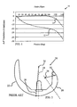
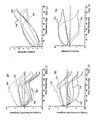
- the line 12 of the graph 10 indicates that the lateral condyle exhibits a constant anterior to posterior translation through deep flexion while the line 14 indicates that the medial condyle remains at about the same location on the tibial plateau until about 90° of flexion. Beyond 90° of flexion, the medial condyle exhibits anterior to posterior translation.
- the medial and lateral condyle low (tangency) points are not the actual contact points between the condyles and the femoral plane. Rather, the points represent the lowest portion of the condyle that can be viewed using fluoroscopy. The actual contact point is generally at a location more posterior to the low (tangency) points. Nonetheless, the use of low (tangency) points provides a valid basis for comparison of the effect of changing design variables between components.
- the PCL is retained.
- patients frequently encounter an unnatural (paradoxical) anterior translation of the contact point between the lateral condyle of the femur and the tibia during deep knee-bend movements.
- Paradoxical anterior translation is typically initiated between 30 and 40° of flexion although it can commence at up to about 120° of flexion.
- the resulting loss of joint stability can accelerate wear, cause a sensation of instability during certain activities of daily living, result in abnormal knee joint motion (kinematics), and/or result in a reduced dynamic moment arm to the quadriceps requiring increased force to control movement.
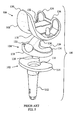
- FIG. 2 depicts a sagittal view of a typical prior art femoral component 20 which attempts to mimic the shape of a native knee.
- the femoral component 20 includes an extension region 22 which is generally anterior to the line 24 and a flexion region 26 which is posterior to the line 24.
- the extension region 22 is formed with a large radius of curvature (R c ) 28 while a small R c 30 is used in the posterior portion of the flexion region 26 in order to fit within the joint space while providing as much flexion as possible.
- R c radius of curvature
- a consequence of the change of the radius of curvature is that the origin of the radius of curvature changes from the origin 32 for the R c 28 to the origin 34 for the R c 30.
- the results of a deep knee bending simulation using a typical prior art femoral component with condylar surfaces in the flexion area defined by a reduced radius of curvature are shown in the translation chart 40 of FIG. 3 which shows the position on the tibial component (y-axis) at which the medial and lateral condyles contact the tibial component as the device is moved through flexion (x-axis).
- the simulation was conducted on a multibody dynamics program commercially available from Biomechanics Research Group, Inc. of San Clemente, California, under the name LifeMOD/KneeSIM.
- the model included tibio-femoral and patello-femoral contact, passive soft tissue, and active muscle elements.
- the lines 42 and 44 in the chart 40 show the estimated low (tangency) points for the lateral condylar surface and the medial condylar surface, respectively. Both of the lines 42 and 44 initially track posteriorly (downwardly as viewed in FIG. 3 ) between 0° and about 30° of flexion. This indicates that the femoral component is rolling posteriorly on the tibial component as the flexion angle increases. Beyond about 30° of flexion, the estimated lateral condyle low (tangency) point line 42 drifts slightly anteriorly from about 5 mm translation while the estimated medial condylar low (tangency) point line 44 moves rapidly anteriorly. Movement of both surfaces in the anterior direction shows that paradoxical anterior translation is occurring beyond about 30°. A comparison of the lines 42 and 44 beyond 30° of flexion with the lines 12 and 14 of FIG. 1 reveals a striking disparity in kinematics between the native knee and the replacement knee which mimics the geometry of the native knee.
- the forces exerted by soft-tissues on the knee are coordinated to provide a smooth movement based, in part, upon the length of the R c 28 and the origin 32.
- the knee may initially be controlled as if it will continue to move along the R c 28.
- the femoral component 20 continues to move, the actual configuration of the knee diverges from the configuration that would be achieved if the surface in contact with the tibial component (not shown) was still defined by the R c 28.
- the soft-tissue forces are rapidly re-configured to a configuration appropriate for movement along the surface defined by the R c 30 with the origin 34. This sudden change in configuration, which is not believed to occur with a native knee, contributes to the sense of instability.
- an initial ratio of about 0.008° of external rotation per degree of flexion is exhibited between 0° and 120° of flexion which increases to a ratio of 0.67° of external rotation per degree of flexion between 120° and 150° of flexion. This rotation allows the knee to move into deep flexion.
- the reported external rotation of the native knee is supported by the data in FIG. 1 .
- the slope of the line 12 is constantly downward indicating that the lowest point of the lateral condylar surface is continuously tracking posteriorly.
- the line 14, however, is moving anteriorly from about 9° of flexion through 90° of flexion.
- the femoral component is externally rotating as the knee moved from about 9° of flexion to about 90° of flexion.
- the lines 12 and 14 show that both condylar surfaces are moving posteriorly.
- the lateral condylar surface is moving more rapidly in the posterior direction. Accordingly, the gap between the lines 12 and 14 continues to expand beyond 90°, indicating that additional external rotation of the knee is occurring.
- FIG. 4 shows the internal rotation of the tibia with respect to the femur (which from a modelling perspective is the same as external rotation of the femur with respect to the tibia, both of which are identified herein as " ⁇ i-e ”) during the testing that provided the results of FIG. 3 .
- the graph 50 includes a line 52 which shows that as the tested component was manipulated to 130° of flexion, the ⁇ i-e reached a maximum of about 7°. Between about 0° of flexion and 20° of flexion, the ⁇ i-e varies from 1° to 0° for a change rate of-0.05° of internal rotation per degree of flexion.
- the internal rotation varies from 0° to 1° for a change rate of 0.03° of internal rotation per degree of flexion.
- the graph 50 exhibits a nearly linear increase in internal rotation from about 1° to about 7° for a change rate of 0.075° of internal rotation per degree of flexion. Accordingly, the ⁇ i-e of a knee joint incorporating the prior art femoral component differs significantly from the ⁇ i-e of a native knee.
- RP rotating platform
- the axis of rotation of the tibial insert on a tibial plateau has typically been positioned between locations coincident with the tibio-femoral dwell points (the low or tangency points of the femoral component when the joint is in full extension) and locations removed from the tibio-femoral dwell points in the anterior direction.
- US-5395401 discloses a knee joint prosthesis which comprises a tibial part having a downwardly extending post and a femoral part.
- a bearing is mounted on the tibial part so that it can slide on the upward face of the tibial part.
- the bearing has a guide track formed in its tibial-engaging surface.
- a coupling part can rotate around an axis defined by the post on the tibial part.
- the coupling part includes a guide portion which extends parallel to the upward face of the tibial part and can be received in the guide track in the bearing, to define a sliding path for the bearing on the tibial part.
- the invention provides a knee prosthesis which more closely reproduces the inherent stability and kinematics of a native knee by managing ⁇ i-e , especially while allowing a degree of rollback of the femoral component on the tibial plateau.
- the invention provides a knee replacement system as defined in claim 1.
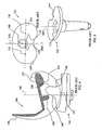
- FIG. 5 shows a knee replacement system 100 which includes a tibial tray 102, a tibial bearing insert 104 and a femoral component 106 having two femoral condyle elements 108 and 110.
- the tibial tray 102 includes an inferior stem 112 for attaching the tibial tray 102 to the tibia of a patient and a superior plateau 114 for receiving the tibial bearing insert 104.
- a coupling member 116 is located on the superior plateau 114.
- the tibial bearing insert 104 includes an inferior tibial tray contacting surface 118 and a superior tibial bearing surface 120
- the superior tibial bearing surface 120 includes a bearing surface 122 and a bearing surface 124 configured to articulate with the femoral condyle elements 108 and 110.
- a spine 126 extends upwardly from between the bearing surface 122 and the bearing surface 124.
- a coupling member 128 extends downwardly from the tibial tray contacting surface 118
- the femoral component 106 is configured to be attached to the femur of a patient.
- a trochlear groove 130 is formed between the femoral condyle elements 108 and 110 which, in this embodiment, are symmetrical.
- the trochlear groove 130 provides an articulation surface for a patellar component (not shown).
- a cam compartment 132 is located between posterior portions 134 and 136 of the femoral condyle elements 108 and 110, respectively.
- Two pegs 138 and 140 are used to mount the femoral component 106 on to the femur of a patient.
- FIG. 6 shows a cross sectional view of the femoral component 106 taken through the cam compartment 132 and a side plan view of the tibial bearing insert 104.
- An anterior cam 142 and a posterior cam 144 are located within the cam compartment 136.
- the spine 126 includes an anterior camming portion 146 and a posterior camming portion 148.
- the anterior cam 142 is configured with the anterior camming portion 146 to preclude undesired posterior slippage when the femoral component 106 is positioned on the tibial bearing insert 104 in extension as shown in FIG. 6 .
- the femoral component 106 is shown in FIG. 6 in full extension.
- the low or tangency point of the femoral component 106 is identified as condylar dwell point 150.
- the condylar dwell point 150 and the condylar dwell point 152 for the condyle element 110 shown projected on to the superior plateau in FIG. 7 , defme a dwell axis 154.
- the dwell axis 154 intersects the centerline 156 of the tibial superior bearing surface 120 at a point defined herein as the "dwell point" 158.
- the dwell point 158 is located posteriorly to the coupling member 116 which, along with the coupling member 128, defines an axis of rotation 160 for the tibial bearing insert 104 (see FIG. 8 ).
- the axis of rotation 160 is positioned anteriorly of the dwell point 158.
- a deep knee bending simulation was conducted on an existing device similar to the knee replacement system 100.
- the existing device was a rotating platform total knee system commercially available from Zimmer Inc of Warsaw Indiana under the trade mark NexGen LPS-flex.
- the design parameters of the existing device that were modelled for the simulation were obtained by reverse engineering.
- the simulation was conducted using the LifeMOD/KneeSIM version 2007.1.0 Beta 12 and later (LMKS) dynamics program discussed above.
- the LMKS was configured to model the MCL, and LCL, as well as capsular tissue, as linear springs and the patellar tendon and ligament allowed to wrap around the implants.
- the components were positioned so that the dwell point of the insert of the tibio-femoral contact surface lined up in the sagittal plane with the mechanical axis of the leg and the original joint line of the knee was restored.
- the patellar ligament angle in the sagittal plane at full extension was determined by placing the patellar component at an appropriate supero-inferior position, centered within the trochlear groove of the femoral component and the patellar ligament in the coronal plane was determined by using the default settings of LMKS, which resulted in a Q-angle of about 12° in the coronal plane with the knee at full extension.
- the rectus femoris coronal angle at full extension was about 7° and the coronal patellar ligament angle at full extension was about 5° from the vertical mechanical axis of the leg at full extension.
- the results of the above defined modelling exercise included the anterior-posterior positions of the lowest points on the femoral lateral and medial condyles closest to the tibial tray which were recorded relative to the dwell points. Additionally, rotation of the tibia relative to the femur and rotation of the tibial insert relative to the tibial tray was reported using the Grood & Suntay coordinate system.
- the reference numbers for the corresponding component of the knee replacement system 100 will be referenced, with the condyle 108 designated as the medial condyle and the condyle 110 designated as the lateral condyle.
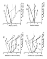
- the graph 170 includes lines 172 and 174 which show the estimated low (tangency) points for the lateral condylar surface 110 and the medial condylar surface 108, respectively, of the femoral component 106 on the tibial bearing insert 104.
- the graph 170 further includes lines 176 and 178 which show the estimated low (tangency) points for the lateral condylar surface 110 and the medial condylar surface 108, respectively, of the femoral component 106 with respect to the tibial tray 102.
- the lower portion of the lines 172, 174, 176 and 178 were generated as the components were moving into flexion.
- the graph 170 generally shows the femoral component 106 is moving posteriorly or "rolling back" on the tibial bearing insert 104 until about 20° of flexion and again from about 90° of flexion to 150° of flexion.
- the amount of rollback of the lateral condylar surface 110 and the medial condylar surface 108 is not the same. This difference indicates that the femoral component 106 is rotating.
- This conclusion is supported by the LMKS Modelling Results for the femoral component 106 on the tibial bearing insert 104 shown in the graph 180 of FIG. 10 in which the line 182 of the graph 180 identifies the ⁇ i-e of the femoral component 106 with respect to the tibia.
- the line 182 reveals that between 0° of flexion and about 100° of flexion, the ⁇ i-e for the femoral component 106 with respect to the tibia is steadily increasing to about 3.5°.
- the graph 180 further includes a line 184 which identifies the rotation of the tibial bearing insert 104 with respect to the tibia.
- the line 184 in contrast to the line 182, reveals that between 0° of flexion and about 90° of flexion, the rotation for the tibial bearing insert 104 with respect to the tibia is steadily decreasing to about -2.5°, indicating a maximum difference in rotation between the femoral component 106 and the tibial bearing insert 104 of about 5° between about 90 and about 110° of flexion.
- Reverse engineering of the prior art system used in the foregoing Modelling scenario indicates that the axis of rotation 160 of the tibial bearing insert 104 of the existing device was located 12.7 mm (0.5 inch) anterior to the dwell point 158 (the "0.5A configuration").
- the model of the existing device was then modified to place the axis of rotation 160 of the tibial bearing insert 104 at 5.0 mm (0.2 inch) anterior to the dwell point 158 (the "0.2A configuration”).
- LMKS Modelling Results for the 0.2A configuration are shown in FIG.
- the graph 190 includes lines 192 and 194 which show the estimated low (tangency) points for the lateral condylar surface 110 and the medial condylar surface 108, respectively, of the femoral component 106 on the tibial bearing insert 104.
- the graph 190 further includes lines 196 and 198 which show the estimated low (tangency) points for the lateral condylar surface 110 and the medial condylar surface 108, respectively, of the femoral component 106 with respect to the tibial tray 102.
- the lower portion of the lines 192, 194, 196, and 198 were generated as the components were moving into flexion.
- the graph 190 generally shows the femoral component 106 is moving posteriorly or "rolling back" on the tibial bearing insert 104 until about 20° of flexion and again from about 90° of flexion to 150° of flexion.
- the rollback exhibited with the 0.2A configuration is substantially the same as the rollback exhibited in the 0.5A configuration.
- the graph 200 of FIG. 12 includes the line 202 which identifies the ⁇ i-e of the femoral component 106 with respect to the tibia.
- the line 202 reveals that between 0° of flexion and about 100° of flexion, the ⁇ i-e for the femoral component 106 with respect to the tibia is steadily increasing to over 4°.
- the graph 200 further includes a line 204 which identifies the rotation of the tibial bearing insert 104 with respect to the tibia.
- the line 204 reveals that between 0° of flexion and about 20° of flexion, there is a slight decrease in the rotation of the tibial bearing insert 104 with respect to the tibia, followed by a steady increase through about 120° of flexion.
- the maximum difference in rotation between the femoral component 106 and the tibial bearing insert 104 is reduced to less than 4° at about 90° of flexion.
- the model of the existing device was then modified to place the axis of rotation 160 of the tibial bearing insert 104 at the dwell point 158 (the "0.0 configuration").
- LMKS Modelling Results for the 0.0A configuration are shown in FIG. 13 in which the graph 210 includes lines 212 and 214 which show the estimated low (tangency) points for the lateral condylar surface 110 and the medial condylar surface 108, respectively, of the femoral component 106 on the tibial bearing insert 104.
- the graph 210 further includes lines 216 and 218 which show the estimated low (tangency) points for the lateral condylar surface 110 and the medial condylar surface 108, respectively, of the femoral component 106 with respect to the tibial tray 102.
- the lower portion of the lines 212, 214, 216 and 218 were generated as the components were moving into flexion.
- the graph 210 generally shows the femoral component 106 is moving posteriorly or "rolling back" on the tibial bearing insert 104 until about 20° of flexion and again from about 90° of flexion to 150° of flexion.
- the rollback exhibited with the 0.0 configuration is substantially the same as the rollback exhibited in the 0.5A configuration.
- the graph 220 of FIG. 14 includes the line 222 which identifies the ⁇ i-e of the femoral component 106 with respect to the tibia.
- the line 222 reveals that between 0° of flexion and about 100 of flexion, the ⁇ i-e for the femoral component 106 with respect to the tibia is steadily increasing to almost 5°.
- the graph 220 further includes a line 224 which identifies the rotation of the tibial bearing insert 104 with respect to the tibia.
- the line 224 reveals that between 0° of flexion and about 20° of flexion, there is a slight decrease in the rotation of the tibial bearing insert 104 with respect to the tibia, followed by a steady increase through about 120° of flexion.
- the maximum difference in rotation between the femoral component 106 and the tibial bearing insert 104 is reduced to less than 2.5° at about 90° of flexion.
- the maximum difference in rotation remains about the same, but the line 224 conforms more closely to the line 222.
- the model of the existing device was then modified to place the axis of rotation 160 of the tibial bearing insert 104 at 12.7 mm (0.5 inch) posterior to the dwell point 158 (the "0.5P configuration").
- LMKS Modelling Results for the 0.5P configuration are shown in FIG. 15 in which the graph 230 includes lines 232 and 234 which show the estimated low (tangency) points for the lateral condylar surface 110 and the medial condylar surface 108, respectively, of the femoral component 106 on the tibial bearing insert 104.
- the graph 230 further includes lines 236 and 238 which show the estimated low (tangency) points for the lateral condylar surface 110 and the medial condylar surface 108, respectively, of the femoral component 106 with respect to the tibial tray 102.
- the lower portion of the lines 232, 234, 236, and 238 were generated as the components were moving into flexion.
- the graph 230 generally shows the femoral component 106 is moving posteriorly or "rolling back" on the tibial bearing insert 104 until about 20° of flexion and again from about 90° of flexion to 150° of flexion.
- the rollback exhibited with the 0.5P configuration is substantially the same as the rollback exhibited in the 0.5A configuration.
- the graph 240 of FIG. 16 includes the line 242 which identifies the ⁇ i-e of the femoral component 106 with respect to the tibia.
- the line 242 reveals that between 0° of flexion and about 100° of flexion, the ⁇ i-e for the femoral component 106 with respect to the tibia is steadily increasing to almost 6°.
- the graph 240 further includes a line 244 which identifies the rotation of the tibial bearing insert 104 with respect to the tibia.
- the line 244 reveals that between 0° of flexion and about 10° of flexion, there is a slight decrease in the rotation of the tibial bearing insert 104 with respect to the tibia, followed by a steady increase through about 120° of flexion. Accordingly, the maximum difference in rotation between the femoral component 106 and the tibial bearing insert 104 is reduced to just over 1° at about 95° of flexion.
- the line 244 conforms very closely with the line 242.
- the excursion of the line 244 above the line 242 as the joint travels toward a flexed position in the 0.5P configuration is somewhat larger than the excursion of the line 224 above the line 222 in the 0.0 configuration.
- FIGs. 9 to 16 show that, as the axis of rotation 160 is moved posteriorly, increased fidelity between the rotation of the femoral component 106 with respect to the tibial tray 102 and the rotation of the tibial bearing insert 104 with respect to the tibial tray 102 is realized. Additionally, the ⁇ i-e for the femoral component 106 with respect to the tibia more than doubles.
- the model of the differently configured device was established with the axis of rotation 160 of the tibial bearing insert 104 at the centerline 156 and 8.0 mm (0.317 inch) anterior to the dwell point 158 (the "0/0.317A configuration").
- LMKS Modelling Results for the 0/0.317A configuration are shown in FIG. 17 in which the graph 250 includes lines 252 and 254 which show the estimated low (tangency) points for the lateral condylar surface 110 and the medial condylar surface 108, respectively, of the femoral component 106 on the tibial bearing insert 104.
- the graph 250 further includes lines 256 and 258 which show the estimated low (tangency) points for the lateral condylar surface 110 and the medial condylar surface 108, respectively, of the femoral component 106 with respect to the tibial tray 102.
- the lower portion of the lines 252, 254, 256, and 258 were generated as the components were moving into flexion.
- the graph 250 generally shows the femoral component 106 is moving posteriorly or "rolling back" on the tibial bearing insert 104 until about 30° of flexion and again from about 105° of flexion to 130° of flexion.
- the graph 260 of FIG. 18 includes the line 262 which identifies the ⁇ i-e of the femoral component 106 with respect to the tibia.
- the line 262 reveals that between 0° of flexion and about 120° of flexion, the ⁇ i-e for the femoral component 106 with respect to the tibia is steadily increasing to just over 5°.
- the graph 260 further includes a line 264 which identifies the rotation of the tibial bearing insert 104 with respect to the tibia.
- the line 264 reveals that between 0° of flexion and about 70° of flexion, there is a steady decrease in the rotation of the tibial bearing insert 104 with respect to the tibia, followed by a relatively constant rotation angle through about 130° of flexion.
- the maximum difference in rotation between the femoral component 106 and the tibial bearing insert 104 constantly increases to about 10° at about 120° of flexion. The maximum difference was about 10° on subsequent cycles.
- the model of the differently configured device was then modified to place the axis of rotation 160 of the tibial bearing insert 104 on the centerline 156 at the dwell point 158 (the "0/0 configuration").
- LMKS Modelling Results for the 0/0 configuration are shown in FIG. 19 in which the graph 270 includes lines 272 and 274 which show the estimated low (tangency) points for the lateral condylar surface 110 and the medial condylar surface 108, respectively, of the femoral component 106 on the tibial bearing insert 104.
- the graph 270 further includes lines 276 and 278 which show the estimated low (tangency) points for the lateral condylar surface 110 and the medial condylar surface 108, respectively, of the femoral component 106 with respect to the tibial tray 102.
- the lower portion of the lines 272, 274, 276, and 278 were generated as the components were moving into flexion.
- the graph 270 generally shows the femoral component 106 is moving posteriorly or "rolling back" on the tibial bearing insert 104 until about 30° of flexion and again from about 95° of flexion to 130° of flexion.
- the rollback exhibited with the 0/0 configuration is substantially the same as the rollback exhibited in the 0/0.317A configuration, although the second rollback event occurred at an earlier flexion angle.
- the graph 280 of FIG. 20 includes the line 282 which identifies the ⁇ i-e of the femoral component 106 with respect to the tibia.
- the line 282 reveals that between 0° of flexion and about 130° of flexion, the ⁇ i-e for the femoral component 106 with respect to the tibia is steadily increasing to over 7°.
- the graph 280 further includes a line 284 which identifies the rotation of the tibial bearing insert 104 with respect to the tibia.
- the line 284 reveals that between 0° of flexion and about 65° of flexion, there is a steady decrease in the rotation of the tibial bearing insert 104 with respect to the tibia, followed by a steady increase through about 105° of flexion.
- the maximum difference in rotation between the femoral component 106 and the tibial bearing insert 104 is reduced to about 8° at about 65° of flexion and slightly more than 8° at about 130° of flexion.
- the maximum difference at 65° was reduced to about 5° while the maximum difference at 130 remained at slightly more than 8°.
- the model of the differently configured device was then modified to place the axis of rotation 160 of the tibial bearing insert 104 at 8.0 mm (0.317 inch) lateral of the centerline 156 and on the dwell axis 154 (the "0.317L/0 configuration").
- LMKS Modelling Results for the 0.317L/0 configuration are shown in FIG. 21 in which the graph 290 includes lines 292 and 294 which show the estimated low (tangency) points for the lateral condylar surface 110 and the medial condylar surface 108, respectively, of the femoral component 106 on the tibial bearing insert 104.
- the graph 290 further includes lines 296 and 298 which show the estimated low (tangency) points for the lateral condylar surface 110 and the medial condylar surface 108, respectively, of the femoral component 106 with respect to the tibial tray 102.
- the lower portion of the lines 292, 294, 296, and 298 were generated as the components were moving into flexion.
- the graph 290 generally shows the femoral component 106 is moving posteriorly or "rolling back" on the tibial bearing insert 104 until just over 30° of flexion and again from about 95° of flexion to 130° of flexion.
- the rollback exhibited with the 0.317L/0 configuration is similar to the rollback exhibited in the 0/0.317A configuration.
- the graph 300 of FIG. 22 includes the line 302 which identifies the ⁇ i-e of the femoral component 106 with respect to the tibia.
- the line 302 reveals that between 0° of flexion and about 130° of flexion, the ⁇ i-e for the femoral component 106 with respect to the tibia is steadily increasing to over 11°.
- the graph 300 further includes a line 304 which identifies the rotation of the tibial bearing insert 104 with respect to the tibia.
- the line 304 reveals that between 0° of flexion and about 110° of flexion, there is a steady increase in the rotation of the tibial bearing insert 104 with respect to the tibia to about 8°, followed by a drop to about 7° of rotation at 130° of flexion.
- the rotation of the tibial bearing insert 104 with respect to the tibia is slightly greater than or equal to the ⁇ i-e for the femoral component 106 through about 100° of flexion with a maximum difference in rotation between the femoral component 106 and the tibial bearing insert 104 of just over 5° at 130° of flexion.
- the maximum difference in rotation of the tibial bearing insert 104 with respect to the tibia is slightly increased, pushing the crossover point to about 115° of flexion with a maximum difference in rotation between the femoral component 106 and the tibial bearing insert 104 of about 4° at 130° of flexion.
- the model of the differently configured device was then modified to place the axis of rotation 160 of the tibial bearing insert 104 at 8.0 mm (0.317 inch) medial of the centerline 156 and on the dwell axis 154 (the "0.317M/0 configuration").
- LMKS Modelling Results for the 0.317M/0 configuration are shown in FIG. 23 in which the graph 310 includes lines 312 and 314 which show the estimated low (tangency) points for the lateral condylar surface 110 and the medial condylar surface 108, respectively, of the femoral component 106 on the tibial bearing insert 104.
- the graph 310 further includes lines 316 and 318 which show the estimated low (tangency) points for the lateral condylar surface 110 and the medial condylar surface 108, respectively, of the femoral component 106 with respect to the tibial tray 102.
- the lower portion of the lines 312, 314, 316, and 318 were generated as the components were moving into flexion.
- the graph 310 generally shows the lateral condyle element 110 of the femoral component 106 is moving posteriorly or "rolling back" on the tibial bearing insert 104 until about 65° of flexion while the medial condyle 108 exhibits rollback to about 35° of flexion.
- the femoral component 106 exhibits additional rollback from about 105° of flexion to 130° of flexion.
- the graph 320 of FIG. 24 includes the line 322 which identifies the ⁇ i-e of the femoral component 106 with respect to the tibia.
- the line 322 reveals that between 0° of flexion and about 115° of flexion, the ⁇ i-e for the femoral component 106 with respect to the tibia is steadily increasing to just under 5°.
- the graph 320 further includes a line 324 which identifies the rotation of the tibial bearing insert 104 with respect to the tibia.
- the line 324 reveals that between 0° of flexion and about 50° of flexion, there is a steady decrease in the rotation of the tibial bearing insert 104 with respect to the tibia, followed by a relatively constant rotation of about -5° through about 130° of flexion.
- the maximum difference in rotation between the femoral component 106 and the tibial bearing insert 104 is about 11° at about 130° of flexion. On subsequent cycles, the maximum difference in rotation was also about 11°.
- the model of the differently configured device was then modified with the axis of rotation 160 of the tibial bearing insert 104 on the centerline 156 and 8.0 mm (0.317 inch) posterior to the dwell axis 154 (the "0/0.317P configuration").
- LMKS Modelling Results for the 0/0.317P configuration are shown in FIG. 25 in which the graph 330 includes lines 332 and 334 which show the estimated low (tangency) points for the lateral condylar surface 110 and the medial condylar surface 108, respectively, of the femoral component 106 on the tibial bearing insert 104.
- the graph 330 further includes lines 336 and 338 which show the estimated low (tangency) points for the lateral condylar surface 110 and the medial condylar surface 108, respectively, of the femoral component 106 with respect to the tibial tray 102.
- the lower portion of the lines 332, 334, 336, and 338 were generated as the components were moving into flexion.
- the graph 330 generally shows the femoral component 106 is moving posteriorly or "rolling back" on the tibial bearing insert 104 until about 35° of flexion and again from about 95° of flexion to 130° of flexion.
- the graph 340 of FIG. 26 includes the line 342 which identifies the ⁇ i-e of the femoral component 106 with respect to the tibia.
- the line 342 reveals that between 0° of flexion and about 130° of flexion, the ⁇ i-e for the femoral component 106 with respect to the tibia is steadily increasing to almost 9°.
- the graph 340 further includes a line 344 which identifies the rotation of the tibial bearing insert 104 with respect to the tibia.
- the line 344 reveals that between 0° of flexion and about 55° of flexion, there is a slight decrease in the rotation of the tibial bearing insert 104 with respect to the tibia, followed by a steady increase through about 105° of flexion followed by a steady decrease in rotation.
- the maximum difference in rotation between the femoral component 106 and the tibial bearing insert 104 is about 9° at about 130° of flexion.
- the rotation of the tibial bearing insert 104 with respect to the tibia remained at about 3° of rotation until about 100° of flexion at which point the rotation angle decreased to about 0°.
- the maximum difference in rotation between the femoral component 106 and the tibial bearing insert 104 was about 9° at about 130° of flexion for the subsequent cycles.
- the model of the differently configured device was then modified with the axis of rotation 160 of the tibial bearing insert 104 to 8.0 mm (0.317 inch) lateral of the centerline 156 and 8.0 mm (0.317 inch) posterior to the dwell axis 154 (the "0.317L/0.317P configuration").
- LMKS Modelling Results for the 0.317L/0.317P configuration are shown in FIG. 27 in which the graph 350 includes lines 352 and 354 which show the estimated low (tangency) points for the lateral condylar surface 110 and the medial condylar surface 108, respectively, of the femoral component 106 on the tibial bearing insert 104.
- the graph 350 further includes lines 356 and 358 which show the estimated low (tangency) points for the lateral condylar surface 110 and the medial condylar surface 108, respectively, of the femoral component 106 with respect to the tibial tray 102.
- the lower portion of the lines 352, 354, 356, and 358 were generated as the components were moving into flexion.
- the graph 350 generally shows the femoral component 106 is moving posteriorly or "rolling back" on the tibial bearing insert 104 until about 40° of flexion and again from about 95° of flexion to 130° of flexion.
- the graph 360 of FIG. 28 includes the line 362 which identifies the ⁇ i-e of the femoral component 106 with respect to the tibia.
- the line 362 reveals that between 0° of flexion and about 130° of flexion, the ⁇ i-e for the femoral component 106 with respect to the tibia is steadily increasing to about 11°.
- the graph 360 further includes a line 364 which identifies the rotation of the tibial bearing insert 104 with respect to the tibia.
- the line 364 reveals that between 0° of flexion and about 110° of flexion, there is a steady increase in the rotation of the tibial bearing insert 104 with respect to the tibia to about 10° of rotation, followed by a slight decrease through 130° of flexion.
- the rotation of the tibial bearing insert 104 with respect to the tibia was greater than the ⁇ i-e for the femoral component 106 until about 120° of flexion with the maximum difference in rotation between the femoral component 106 and the tibial bearing insert 104 about 3° at about 60° of flexion.
- the rotation of the tibial bearing insert 104 with respect to the tibia was generally higher, with the maximum difference in rotation between the femoral component 106 and the tibial bearing insert 104 about 6° at about 60° of flexion.
- the model of the differently configured device was then modified with the axis of rotation 160 of the tibial bearing insert 104 8.0 mm (0.317 inch) medial to the centerline 156 and 8.0 mm (0.317 inch) posterior to the dwell axis 154 (the "0.317M/0.317P configuration").
- LMKS Modelling Results for the 0.317M/0.317P configuration are shown in FIG. 29 in which the graph 370 includes lines 372 and 374 which show the estimated low (tangency) points for the lateral condylar surface 110 and the medial condylar surface 108, respectively, of the femoral component 106 on the tibial bearing insert 104.
- the graph 370 further includes lines 376 and 378 which show the estimated low (tangency) points for the lateral condylar surface 110 and the medial condylar surface 108, respectively, of the femoral component 106 with respect to the tibial tray 102.
- the lower portion of the lines 372, 374, 376, and 378 were generated as the components were moving into flexion.
- the graph 370 generally shows the lateral condyle element 110 of the femoral component 106 is moving posteriorly or "rolling back" on the tibial bearing insert 104 until about 60° of flexion while the medial condyle 108 exhibits rollback to about 20° of flexion.
- the femoral component 106 exhibits additional rollback from about 100° of flexion to 130° of flexion.
- the graph 380 of FIG. 30 includes the line 382 which identifies the ⁇ i-e of the femoral component 106 with respect to the tibia.
- the line 382 reveals that between 0° of flexion and about 130° of flexion, the ⁇ i-e for the femoral component 106 with respect to the tibia is steadily increasing to almost 6°.
- the graph 380 further includes a line 384 which identifies the rotation of the tibial bearing insert 104 with respect to the tibia.
- the line 384 reveals that between 0° of flexion and about 50° of flexion, there is a constant decrease in the rotation of the tibial bearing insert 104 with respect to the tibia to about -5°, followed by a slight increase through about 130° of flexion.
- the maximum difference in rotation between the femoral component 106 and the tibial bearing insert 104 is about 9° at about 130° of flexion. On subsequent cycles, the difference is less early in flexion.
- FIGs. 17 to 30 therefore confirm that the position of the axis of rotation for a rotating plateau system may be used manage the conformity between the rotation of the plateau and the ⁇ i-e for the femoral component of the system. Additionally, the position of the axis of rotation may be used to manage the rollback and rotational characteristics of a rotating plateau system.
- the knee replacement system 400 includes a tibial tray 402, a tibial bearing insert 404 and a femoral component 406 having two femoral condyle elements 408 and 410.
- the tibial tray 402 includes an inferior stem 412 for attaching the tibial tray 402 to the tibia of a patient and a superior plateau 414 for articulating with the tibial bearing insert 404.
- a coupling member 416 is located on the superior plateau 414.
- the tibial bearing insert 404 includes an inferior tibial tray contacting surface 418 and a superior tibial bearing surface 420
- the superior tibial bearing surface 420 includes a medial bearing surface 422 and a lateral bearing surface 424 configured to articulate with the femoral condyle elements 408 and 410.
- a spine 426 extends upwardly from between the bearing surface 422 and the bearing surface 424.
- a pivot 428 extends downwardly from the tibial tray contacting surface 418.
- the femoral component 406 may be similar to the femoral component 106.
- a dwell axis 430, condylar dwell points 432 and 434, and a centerline 436 of the talar bearing insert 404 are shown projected on to the superior plateau 414 and defining a dwell point 438.
- the coupling member 416 in this embodiment is positioned to define an axis of rotation 440 which is located posterior to the projected dwell axis 430 and lateral to the projected centerline 436.
- axis of rotation 438 is located laterally and posteriorly from the dwell point by between about 5.0 and 12.7mm (0.2 and 0.5 inch).
- the axis of rotation 438 is located 8.0 mm (0.317 inch) posterior to the projected dwell axis 430 and 8.0 mm (0.317 inch) lateral to the projected centerline 436.
- the positioning of the axis of rotation is applicable to cruciate-retaining designs, and to cruciate-sacrificing designs in which the ACL is absent.
Landscapes
- Health & Medical Sciences (AREA)
- Orthopedic Medicine & Surgery (AREA)
- Physical Education & Sports Medicine (AREA)
- Cardiology (AREA)
- Oral & Maxillofacial Surgery (AREA)
- Transplantation (AREA)
- Engineering & Computer Science (AREA)
- Biomedical Technology (AREA)
- Heart & Thoracic Surgery (AREA)
- Vascular Medicine (AREA)
- Life Sciences & Earth Sciences (AREA)
- Animal Behavior & Ethology (AREA)
- General Health & Medical Sciences (AREA)
- Public Health (AREA)
- Veterinary Medicine (AREA)
- Prostheses (AREA)
- Water Treatment By Sorption (AREA)
- Lock And Its Accessories (AREA)
- Undergarments, Swaddling Clothes, Handkerchiefs Or Underwear Materials (AREA)
Claims (5)
- Système de remplacement de genou (400) comprenant :➢ un composant fémoral (406) comprenant une partie articulée condylienne latérale (410) et une partie articulée condylienne médiale (408) ;➢ un plateau tibial (402) comprenant une surface articulée supérieure (414) ; et➢ un insert tibial (404) comprenant (i) une première partie articulée (424) adaptée pour s'articuler avec la partie articulée condylienne latérale avec un premier point condylien stationnaire (432), (ii) une seconde partie articulée (422) adaptée pour s'articuler avec la partie articulée condylienne médiale avec un second point condylien stationnaire (434), (iii) une surface articulée inférieure (418) adaptée pour s'articuler avec la surface articulée supérieure, et (iv) un organe de couplage (428) adapté pour se coupler au plateau tibial et définir un axe de rotation autour duquel l'insert tibial tourne par rapport au plateau tibial,caractérisé en ce que l'axe de rotation de l'insert tibial par rapport au plateau tibial est fixe par rapport au plateau tibial et à l'insert tibial de telle sorte qu'il coupe la surface articulée supérieure (420) à une position postérieure à un axe stationnaire (430) qui s'étend entre le premier point condylien stationnaire et le second point condylien stationnaire quand l'axe stationnaire est projeté sur la surface articulée supérieure.
- Système de remplacement de genou selon la revendication 1, dans lequel l'axe de rotation coupe une ligne médiane (436) de l'insert tibial quand la ligne médiane est projetée sur la surface articulée supérieure (414).
- Système de remplacement de genou selon la revendication 2, dans lequel l'axe de rotation coupe une ligne médiane (436) de l'insert tibial à un emplacement entre environ 5,0 mm et environ 12,7 mm (0,2 pouce et 0,5 pouce), de préférence à environ 7, 6 mm (0,3 pouce), postérieur à l'intersection de la ligne médiane projetée et de l'axe stationnaire projeté (430).
- Système de remplacement de genou selon la revendication 1, dans lequel l'axe de rotation coupe la surface articulée supérieure (414) à un emplacement latéral par rapport à la ligne médiane (436) de l'insert tibial quand la ligne médiane est projetée sur la surface articulée supérieure.
- Système de remplacement de genou selon la revendication 4, dans lequel l'axe de rotation coupe la surface articulée supérieure (414) à un emplacement entre environ 5,0 mm et environ 12,7 mm (0,2 pouce et 0,5 pouce), de préférence à environ 10,1 mm (0,4 pouce), à l'écart de l'intersection de la ligne médiane projetée (436) et de l'axe stationnaire projeté (430).
Applications Claiming Priority (1)
| Application Number | Priority Date | Filing Date | Title |
|---|---|---|---|
| US12/174,507 US7981159B2 (en) | 2008-07-16 | 2008-07-16 | Antero-posterior placement of axis of rotation for a rotating platform |
Publications (3)
| Publication Number | Publication Date |
|---|---|
| EP2145605A2 EP2145605A2 (fr) | 2010-01-20 |
| EP2145605A3 EP2145605A3 (fr) | 2010-05-26 |
| EP2145605B1 true EP2145605B1 (fr) | 2011-09-28 |
Family
ID=41128070
Family Applications (1)
| Application Number | Title | Priority Date | Filing Date |
|---|---|---|---|
| EP09164478A Active EP2145605B1 (fr) | 2008-07-16 | 2009-07-02 | Système de remplacement de genou |
Country Status (8)
| Country | Link |
|---|---|
| US (1) | US7981159B2 (fr) |
| EP (1) | EP2145605B1 (fr) |
| JP (1) | JP5410181B2 (fr) |
| CN (1) | CN101627930B (fr) |
| AT (1) | ATE525981T1 (fr) |
| AU (1) | AU2009202848B2 (fr) |
| DK (1) | DK2145605T3 (fr) |
| ES (1) | ES2371595T3 (fr) |
Families Citing this family (53)
| Publication number | Priority date | Publication date | Assignee | Title |
|---|---|---|---|---|
| US6719800B2 (en) | 2001-01-29 | 2004-04-13 | Zimmer Technology, Inc. | Constrained prosthetic knee with rotating bearing |
| US6485519B2 (en) | 2001-01-29 | 2002-11-26 | Bristol-Myers Squibb Company | Constrained prosthetic knee with rotating bearing |
| US9592127B2 (en) | 2005-12-15 | 2017-03-14 | Zimmer, Inc. | Distal femoral knee prostheses |
| US8632600B2 (en) | 2007-09-25 | 2014-01-21 | Depuy (Ireland) | Prosthesis with modular extensions |
| US9204967B2 (en) | 2007-09-28 | 2015-12-08 | Depuy (Ireland) | Fixed-bearing knee prosthesis having interchangeable components |
| WO2009105496A1 (fr) * | 2008-02-18 | 2009-08-27 | Maxx Orthopedics, Inc. | Prothèse de remplacement du genou complet |
| US8078440B2 (en) | 2008-09-19 | 2011-12-13 | Smith & Nephew, Inc. | Operatively tuning implants for increased performance |
| US8491662B2 (en) | 2008-12-23 | 2013-07-23 | Aesculap Ag | Knee prosthesis |
| WO2011016905A1 (fr) | 2009-07-27 | 2011-02-10 | Thomas P Andriacchi | Système de remplacement du genou et procédé pour permettre un mouvement naturel du genou |
| US8998997B2 (en) | 2009-08-11 | 2015-04-07 | Michael D. Ries | Implantable mobile bearing prosthetics |
| US9095453B2 (en) * | 2009-08-11 | 2015-08-04 | Michael D. Ries | Position adjustable trial systems for prosthetic implants |
| US8382848B2 (en) * | 2009-08-11 | 2013-02-26 | Imds Corporation | Position adjustable trial systems for prosthetic implants |
| US8496666B2 (en) | 2009-08-11 | 2013-07-30 | Imds Corporation | Instrumentation for mobile bearing prosthetics |
| US8568485B2 (en) * | 2009-08-11 | 2013-10-29 | Imds Corporation | Articulating trials for prosthetic implants |
| TWI554076B (zh) * | 2009-09-04 | 2016-10-11 | 普露諾洛股份有限公司 | 遠距離的電話管理器 |
| US8870964B2 (en) * | 2009-11-16 | 2014-10-28 | New York Society For The Ruptured And Crippled Maintaining The Hospital For Special Surgery | Prosthetic condylar joints with articulating bearing surfaces having a translating contact point during rotation thereof |
| US8900315B2 (en) * | 2009-11-16 | 2014-12-02 | New York Society For The Ruptured And Crippled Maintaining The Hospital For Special Surgery | Constrained condylar knee device |
| US9011547B2 (en) * | 2010-01-21 | 2015-04-21 | Depuy (Ireland) | Knee prosthesis system |
| EP2595574B1 (fr) | 2010-07-24 | 2017-05-03 | Zimmer, Inc. | Composants tibiaux asymétriques pour une prothèse de genou |
| US8764840B2 (en) | 2010-07-24 | 2014-07-01 | Zimmer, Inc. | Tibial prosthesis |
| US8591594B2 (en) | 2010-09-10 | 2013-11-26 | Zimmer, Inc. | Motion facilitating tibial components for a knee prosthesis |
| CA2810729C (fr) | 2010-09-10 | 2018-04-10 | Zimmer Gmbh | Prothese femorale a rainure rotulienne |
| US8287601B2 (en) * | 2010-09-30 | 2012-10-16 | Depuy Products, Inc. | Femoral component of a knee prosthesis having an angled cement pocket |
| FR2967346B1 (fr) * | 2010-11-17 | 2012-12-14 | Rodolphe Limozin | Gamme de protheses de genou tricompartimentaires |
| US8603101B2 (en) | 2010-12-17 | 2013-12-10 | Zimmer, Inc. | Provisional tibial prosthesis system |
| US8591593B2 (en) | 2011-04-15 | 2013-11-26 | Biomet Manufacturing, Llc | Pivoting tibial tray |
| US9060868B2 (en) | 2011-06-16 | 2015-06-23 | Zimmer, Inc. | Femoral component for a knee prosthesis with bone compacting ridge |
| US8932365B2 (en) | 2011-06-16 | 2015-01-13 | Zimmer, Inc. | Femoral component for a knee prosthesis with improved articular characteristics |
| US9308095B2 (en) | 2011-06-16 | 2016-04-12 | Zimmer, Inc. | Femoral component for a knee prosthesis with improved articular characteristics |
| US8551179B2 (en) | 2011-06-16 | 2013-10-08 | Zimmer, Inc. | Femoral prosthesis system having provisional component with visual indicators |
| US8617250B2 (en) * | 2011-06-17 | 2013-12-31 | Biomet Manufacturing, Llc | Revision knee tibial locking mechanism |
| US20130080524A1 (en) * | 2011-09-28 | 2013-03-28 | Yigal Dan Rubinstein | Instantaneous recommendation of social interactions in a social networking system |
| EP3848005A3 (fr) | 2011-11-18 | 2021-09-15 | Zimmer, Inc. | Élément porteur tibial pour prothèse du genou présentant des caractéristiques articulaires améliorées |
| AU2012341026B2 (en) | 2011-11-21 | 2015-01-29 | Zimmer, Inc. | Tibial baseplate with asymmetric placement of fixation structures |
| IN2014DN07145A (fr) | 2012-01-30 | 2015-04-24 | Zimmer Inc | |
| CN105228558B (zh) | 2013-03-14 | 2017-06-20 | 捷迈有限公司 | 假膝植入体 |
| BR112015023432A2 (pt) * | 2013-03-15 | 2017-07-18 | Conformis Inc | componentes de implante de joelho estabilizados posteriormente e instrumentos |
| US9445909B2 (en) | 2013-03-15 | 2016-09-20 | Mako Surgical Corp. | Unicondylar tibial knee implant |
| US9925052B2 (en) | 2013-08-30 | 2018-03-27 | Zimmer, Inc. | Method for optimizing implant designs |
| US10466858B2 (en) * | 2013-12-01 | 2019-11-05 | Upskill, Inc. | Systems and methods for interacting with a virtual menu |
| DE102014106012B9 (de) | 2014-04-29 | 2015-09-17 | Aesculap Ag | Kniegelenkendoprothese |
| US10130375B2 (en) | 2014-07-31 | 2018-11-20 | Zimmer, Inc. | Instruments and methods in performing kinematically-aligned total knee arthroplasty |
| CN104783933B (zh) * | 2015-05-08 | 2017-01-25 | 北京爱康宜诚医疗器材股份有限公司 | 胫骨平台组件 |
| EP3352708B1 (fr) | 2015-09-21 | 2020-07-22 | Zimmer, Inc. | Système de prothèse comprenant un élément porteur tibial |
| US10136997B2 (en) | 2015-09-29 | 2018-11-27 | Zimmer, Inc. | Tibial prosthesis for tibia with varus resection |
| DE102015119105A1 (de) | 2015-11-06 | 2017-05-11 | Aesculap Ag | Kniegelenkendoprothese |
| ES2878003T3 (es) | 2017-03-10 | 2021-11-18 | Zimmer Inc | Prótesis tibial con característica de afianzamiento para un componente de apoyo tibial |
| AU2018266322B2 (en) | 2017-05-12 | 2020-03-19 | Zimmer, Inc. | Femoral prostheses with upsizing and downsizing capabilities |
| US11426282B2 (en) | 2017-11-16 | 2022-08-30 | Zimmer, Inc. | Implants for adding joint inclination to a knee arthroplasty |
| US10827971B2 (en) | 2017-12-20 | 2020-11-10 | Howmedica Osteonics Corp. | Virtual ligament balancing |
| US10835380B2 (en) | 2018-04-30 | 2020-11-17 | Zimmer, Inc. | Posterior stabilized prosthesis system |
| US10864082B2 (en) * | 2018-10-19 | 2020-12-15 | Roy D. Bloebaum | Osteolysis-resistant cementless joint implant with improved stability and seating function |
| WO2020222167A1 (fr) * | 2019-05-02 | 2020-11-05 | DePuy Synthes Products, Inc. | Système d'implant orthopédique ayant des caractéristiques de conservation de l'os |
Family Cites Families (55)
| Publication number | Priority date | Publication date | Assignee | Title |
|---|---|---|---|---|
| US4209861A (en) | 1978-02-22 | 1980-07-01 | Howmedica, Inc. | Joint prosthesis |
| US4215439A (en) * | 1978-10-16 | 1980-08-05 | Zimmer, USA | Semi-restraining knee prosthesis |
| US4340978A (en) * | 1979-07-02 | 1982-07-27 | Biomedical Engineering Corp. | New Jersey meniscal bearing knee replacement |
| US4888021A (en) * | 1988-02-02 | 1989-12-19 | Joint Medical Products Corporation | Knee and patellar prosthesis |
| US5071438A (en) * | 1990-11-07 | 1991-12-10 | Intermedics Orthopedics, Inc. | Tibial prothesis with pivoting articulating surface |
| DE69128961T2 (de) * | 1990-11-14 | 1998-10-08 | Arch Dev Corp | Verbesserte knieprothese mit beweglichem lager |
| GB9102348D0 (en) * | 1991-02-04 | 1991-03-20 | Inst Of Orthopaedics The | Prosthesis for knee replacement |
| GB9102633D0 (en) * | 1991-02-07 | 1991-03-27 | Finsbury Instr Ltd | Knee prosthesis |
| US5358527A (en) * | 1991-03-22 | 1994-10-25 | Forte Mark R | Total knee prosthesis with resurfacing and posterior stabilization capability |
| US5395401A (en) * | 1991-06-17 | 1995-03-07 | Bahler; Andre | Prosthetic device for a complex joint |
| US5133758A (en) * | 1991-09-16 | 1992-07-28 | Research And Education Institute, Inc. Harbor-Ucla Medical Center | Total knee endoprosthesis with fixed flexion-extension axis of rotation |
| NZ243181A (en) * | 1992-04-23 | 1994-10-26 | Michael John Pappas | Prosthetic joint with guide means to limit articulation of a first element and bearing means to two degrees of freedom |
| US5824102A (en) * | 1992-06-19 | 1998-10-20 | Buscayret; Christian | Total knee prosthesis |
| FR2692475B1 (fr) | 1992-06-19 | 2000-04-21 | Montpellier Chirurgie | Prothese totale du genou. |
| US5344460A (en) * | 1992-10-30 | 1994-09-06 | Encore Orthopedics, Inc. | Prosthesis system |
| US5658342A (en) * | 1992-11-16 | 1997-08-19 | Arch Development | Stabilized prosthetic knee |
| US5413604A (en) * | 1992-12-24 | 1995-05-09 | Osteonics Corp. | Prosthetic knee implant for an anterior cruciate ligament deficient total knee replacement |
| GB9314832D0 (en) * | 1993-07-16 | 1993-09-01 | Walker Peter S | Prostheses for knee replacement |
| US5549686A (en) * | 1994-06-06 | 1996-08-27 | Zimmer, Inc. | Knee prosthesis having a tapered cam |
| US5571194A (en) * | 1994-11-14 | 1996-11-05 | Johnson & Johnson Professional, Inc. | Femoral augmentation system for artificial knee joint |
| US5639279A (en) * | 1995-02-09 | 1997-06-17 | Intermedics Orthopedics, Inc. | Posteriorly-stabilized prosthetic knee |
| US5683468A (en) | 1995-03-13 | 1997-11-04 | Pappas; Michael J. | Mobile bearing total joint replacement |
| US5609643A (en) * | 1995-03-13 | 1997-03-11 | Johnson & Johnson Professional, Inc. | Knee joint prosthesis |
| DE19529824A1 (de) | 1995-08-14 | 1997-02-20 | Bodo Gnutzmann | Bikondyläre Knie-Endoprothese |
| US5871546A (en) * | 1995-09-29 | 1999-02-16 | Johnson & Johnson Professional, Inc. | Femoral component condyle design for knee prosthesis |
| US5776201A (en) * | 1995-10-02 | 1998-07-07 | Johnson & Johnson Professional, Inc. | Modular femoral trial system |
| US5871543A (en) * | 1996-02-23 | 1999-02-16 | Hofmann; Aaron A. | Tibial prosthesis with mobile bearing member |
| US5964808A (en) * | 1996-07-11 | 1999-10-12 | Wright Medical Technology, Inc. | Knee prosthesis |
| US6039764A (en) * | 1997-08-18 | 2000-03-21 | Arch Development Corporation | Prosthetic knee with adjusted center of internal/external rotation |
| FR2768613B1 (fr) * | 1997-09-23 | 1999-12-17 | Tornier Sa | Prothese de genou a plateau rotatoire |
| US6206926B1 (en) * | 1997-10-06 | 2001-03-27 | Biomedical Engineering Trust I | Prosthetic knee joint with enhanced posterior stabilization and dislocation prevention features |
| US6500208B1 (en) * | 1998-10-16 | 2002-12-31 | Biomet, Inc. | Nonmodular joint prosthesis convertible in vivo to a modular prosthesis |
| FR2787012A1 (fr) | 1998-12-11 | 2000-06-16 | Bex Anne Marie | Endo-prothese de genou |
| US6379388B1 (en) * | 1999-12-08 | 2002-04-30 | Ortho Development Corporation | Tibial prosthesis locking system and method of repairing knee joint |
| US6491726B2 (en) * | 2000-03-08 | 2002-12-10 | Biomedical Engineering Trust I | Posterior stabilized prosthetic knee replacement with bearing translation and dislocation prevention features |
| US6475241B2 (en) * | 2000-03-13 | 2002-11-05 | Biomedical Engineering Trust I | Posterior stabilized knee replacement with bearing translation for knees with retained collateral ligaments |
| FR2812540B1 (fr) | 2000-08-01 | 2002-10-31 | Jean Manuel Aubaniac | Prothese bicompartimentale du genou |
| US20020120340A1 (en) * | 2001-02-23 | 2002-08-29 | Metzger Robert G. | Knee joint prosthesis |
| US6797005B2 (en) * | 2001-02-28 | 2004-09-28 | Biomedical Engineering Trust | Deep flexion posterior stabilized knee replacement with bearing translation |
| US6589283B1 (en) * | 2001-05-15 | 2003-07-08 | Biomet, Inc. | Elongated femoral component |
| EP1460977B1 (fr) * | 2001-12-21 | 2006-08-30 | Smith & Nephew, Inc. | Systeme d'articulation articulee |
| FR2835178B1 (fr) | 2002-01-31 | 2004-12-03 | Jacques Marie Rousseau | Ensemble prothetique tibial pour prothese du genou a glissement |
| GB0204381D0 (en) * | 2002-02-26 | 2002-04-10 | Mcminn Derek J W | Knee prosthesis |
| US20040002767A1 (en) * | 2002-06-28 | 2004-01-01 | Joseph Wyss | Modular knee joint prosthesis |
| US6770099B2 (en) * | 2002-11-19 | 2004-08-03 | Zimmer Technology, Inc. | Femoral prosthesis |
| WO2004058108A1 (fr) * | 2002-12-20 | 2004-07-15 | Smith & Nephew, Inc. | Protheses du genou a hautes performances |
| US6986791B1 (en) * | 2003-04-15 | 2006-01-17 | Biomet Manufacturing Corp. | Knee prosthesis with moveable post |
| CN1845713B (zh) * | 2003-07-17 | 2010-06-02 | 精密技术公司 | 活动支承件膝盖假体 |
| US7261740B2 (en) * | 2003-10-29 | 2007-08-28 | Wright Medical Technology, Inc. | Tibial knee prosthesis |
| DE202004003133U1 (de) * | 2004-02-26 | 2004-07-29 | Aap Implantate Ag | Gelenkersatz-Tibiaplateau |
| JP3915989B2 (ja) * | 2004-03-17 | 2007-05-16 | 徹 勝呂 | 人工膝関節 |
| US20060178749A1 (en) * | 2005-02-10 | 2006-08-10 | Zimmer Technology, Inc. | Modular porous implant |
| CN101431967A (zh) | 2006-03-21 | 2009-05-13 | 理查德·D·科米斯泰克 | 引入力矩的全关节置换假体 |
| US7842093B2 (en) * | 2006-07-18 | 2010-11-30 | Biomet Manufacturing Corp. | Method and apparatus for a knee implant |
| US8236061B2 (en) * | 2008-06-30 | 2012-08-07 | Depuy Products, Inc. | Orthopaedic knee prosthesis having controlled condylar curvature |
-
2008
- 2008-07-16 US US12/174,507 patent/US7981159B2/en not_active Expired - Fee Related
-
2009
- 2009-07-02 DK DK09164478.1T patent/DK2145605T3/da active
- 2009-07-02 ES ES09164478T patent/ES2371595T3/es active Active
- 2009-07-02 AT AT09164478T patent/ATE525981T1/de active
- 2009-07-02 EP EP09164478A patent/EP2145605B1/fr active Active
- 2009-07-14 AU AU2009202848A patent/AU2009202848B2/en active Active
- 2009-07-15 JP JP2009166300A patent/JP5410181B2/ja active Active
- 2009-07-16 CN CN200910160406.5A patent/CN101627930B/zh active Active
Also Published As
| Publication number | Publication date |
|---|---|
| US7981159B2 (en) | 2011-07-19 |
| CN101627930A (zh) | 2010-01-20 |
| EP2145605A2 (fr) | 2010-01-20 |
| AU2009202848A1 (en) | 2010-02-04 |
| ATE525981T1 (de) | 2011-10-15 |
| DK2145605T3 (da) | 2012-01-16 |
| JP2010022826A (ja) | 2010-02-04 |
| EP2145605A3 (fr) | 2010-05-26 |
| AU2009202848B2 (en) | 2015-08-20 |
| CN101627930B (zh) | 2014-06-04 |
| US20100016978A1 (en) | 2010-01-21 |
| ES2371595T3 (es) | 2012-01-05 |
| JP5410181B2 (ja) | 2014-02-05 |
Similar Documents
| Publication | Publication Date | Title |
|---|---|---|
| EP2145605B1 (fr) | Système de remplacement de genou | |
| EP2145606B1 (fr) | Prothèse de genou | |
| US20210137689A1 (en) | Moment induced total arthroplasty prosthetic | |
| EP1400220B1 (fr) | Prothèse de genou postéro-stabilisée avec de la contrainte en varus-valgus | |
| Kuriyama et al. | Malrotated tibial component increases medial collateral ligament tension in total knee arthroplasty | |
| US8715358B2 (en) | PCL retaining ACL substituting TKA apparatus and method | |
| Lew et al. | The effect of knee-prosthesis geometry on cruciate ligament mechanics during flexion. | |
| Zumbrunn et al. | Regaining native knee kinematics following joint arthroplasty: a novel biomimetic design with ACL and PCL preservation | |
| Walker et al. | Design forms of total knee replacement | |
| Zihlmann et al. | Biomechanical background and clinical observations of rotational malalignment in TKA:: Literature review and consequences | |
| Pinskerova et al. | Knee anatomy and biomechanics and its relevance to knee replacement | |
| Koh et al. | Effect of geometric variations on tibiofemoral surface and post-cam design of normal knee kinematics restoration | |
| Haider et al. | Effects of patient and surgical alignment variables on kinematics in TKR simulation under force-control | |
| Walker | A new concept in guided motion total knee arthroplasty | |
| Koh et al. | Patient-specific design for articular surface conformity to preserve normal knee mechanics in posterior stabilized total knee arthroplasty | |
| Lin et al. | Change in collateral ligament length and tibiofemoral movement following joint line variation in TKA | |
| ZA200904949B (en) | Antero-posterior placement of axis of rotation for a rotating platform | |
| Keller et al. | 1 Anatomy and Biomechanics of the Natural Knee and After TKR | |
| Jorgensen et al. | Kinematics of the Native and Arthritic Knee | |
| Pokorný et al. | The patellofemoral joint and the total knee replacement | |
| Wyss | i, United States Patent (10) Patent No.: US 7.981. 159 B2 | |
| Hart et al. | Biomechanics and joint replacement of the knee | |
| Victor | Which implant do I pick? A glossary of promises | |
| Rivière et al. | Knee Anatomy andBiomechanics andits Relevance toKnee Replacement |
Legal Events
| Date | Code | Title | Description |
|---|---|---|---|
| PUAI | Public reference made under article 153(3) epc to a published international application that has entered the european phase |
Free format text: ORIGINAL CODE: 0009012 |
|
| AK | Designated contracting states |
Kind code of ref document: A2 Designated state(s): AT BE BG CH CY CZ DE DK EE ES FI FR GB GR HR HU IE IS IT LI LT LU LV MC MK MT NL NO PL PT RO SE SI SK SM TR |
|
| AX | Request for extension of the european patent |
Extension state: AL BA RS |
|
| PUAL | Search report despatched |
Free format text: ORIGINAL CODE: 0009013 |
|
| AK | Designated contracting states |
Kind code of ref document: A3 Designated state(s): AT BE BG CH CY CZ DE DK EE ES FI FR GB GR HR HU IE IS IT LI LT LU LV MC MK MT NL NO PL PT RO SE SI SK SM TR |
|
| AX | Request for extension of the european patent |
Extension state: AL BA RS |
|
| 17P | Request for examination filed |
Effective date: 20101119 |
|
| GRAP | Despatch of communication of intention to grant a patent |
Free format text: ORIGINAL CODE: EPIDOSNIGR1 |
|
| RIC1 | Information provided on ipc code assigned before grant |
Ipc: A61F 2/38 20060101AFI20110331BHEP |
|
| GRAS | Grant fee paid |
Free format text: ORIGINAL CODE: EPIDOSNIGR3 |
|
| GRAA | (expected) grant |
Free format text: ORIGINAL CODE: 0009210 |
|
| AK | Designated contracting states |
Kind code of ref document: B1 Designated state(s): AT BE BG CH CY CZ DE DK EE ES FI FR GB GR HR HU IE IS IT LI LT LU LV MC MK MT NL NO PL PT RO SE SI SK SM TR |
|
| REG | Reference to a national code |
Ref country code: GB Ref legal event code: FG4D |
|
| REG | Reference to a national code |
Ref country code: CH Ref legal event code: EP |
|
| REG | Reference to a national code |
Ref country code: CH Ref legal event code: NV Representative=s name: E. BLUM & CO. AG PATENT- UND MARKENANWAELTE VSP |
|
| REG | Reference to a national code |
Ref country code: IE Ref legal event code: FG4D |
|
| REG | Reference to a national code |
Ref country code: DE Ref legal event code: R096 Ref document number: 602009002784 Country of ref document: DE Effective date: 20111201 |
|
| REG | Reference to a national code |
Ref country code: NL Ref legal event code: T3 |
|
| REG | Reference to a national code |
Ref country code: ES Ref legal event code: FG2A Ref document number: 2371595 Country of ref document: ES Kind code of ref document: T3 Effective date: 20120105 |
|
| REG | Reference to a national code |
Ref country code: SE Ref legal event code: TRGR |
|
| REG | Reference to a national code |
Ref country code: DK Ref legal event code: T3 |
|
| PG25 | Lapsed in a contracting state [announced via postgrant information from national office to epo] |
Ref country code: LT Free format text: LAPSE BECAUSE OF FAILURE TO SUBMIT A TRANSLATION OF THE DESCRIPTION OR TO PAY THE FEE WITHIN THE PRESCRIBED TIME-LIMIT Effective date: 20110928 Ref country code: HR Free format text: LAPSE BECAUSE OF FAILURE TO SUBMIT A TRANSLATION OF THE DESCRIPTION OR TO PAY THE FEE WITHIN THE PRESCRIBED TIME-LIMIT Effective date: 20110928 Ref country code: NO Free format text: LAPSE BECAUSE OF FAILURE TO SUBMIT A TRANSLATION OF THE DESCRIPTION OR TO PAY THE FEE WITHIN THE PRESCRIBED TIME-LIMIT Effective date: 20111228 |
|
| LTIE | Lt: invalidation of european patent or patent extension |
Effective date: 20110928 |
|
| PG25 | Lapsed in a contracting state [announced via postgrant information from national office to epo] |
Ref country code: CY Free format text: LAPSE BECAUSE OF FAILURE TO SUBMIT A TRANSLATION OF THE DESCRIPTION OR TO PAY THE FEE WITHIN THE PRESCRIBED TIME-LIMIT Effective date: 20110928 Ref country code: SI Free format text: LAPSE BECAUSE OF FAILURE TO SUBMIT A TRANSLATION OF THE DESCRIPTION OR TO PAY THE FEE WITHIN THE PRESCRIBED TIME-LIMIT Effective date: 20110928 Ref country code: LV Free format text: LAPSE BECAUSE OF FAILURE TO SUBMIT A TRANSLATION OF THE DESCRIPTION OR TO PAY THE FEE WITHIN THE PRESCRIBED TIME-LIMIT Effective date: 20110928 Ref country code: GR Free format text: LAPSE BECAUSE OF FAILURE TO SUBMIT A TRANSLATION OF THE DESCRIPTION OR TO PAY THE FEE WITHIN THE PRESCRIBED TIME-LIMIT Effective date: 20111229 |
|
| PG25 | Lapsed in a contracting state [announced via postgrant information from national office to epo] |
Ref country code: SK Free format text: LAPSE BECAUSE OF FAILURE TO SUBMIT A TRANSLATION OF THE DESCRIPTION OR TO PAY THE FEE WITHIN THE PRESCRIBED TIME-LIMIT Effective date: 20110928 Ref country code: IS Free format text: LAPSE BECAUSE OF FAILURE TO SUBMIT A TRANSLATION OF THE DESCRIPTION OR TO PAY THE FEE WITHIN THE PRESCRIBED TIME-LIMIT Effective date: 20120128 Ref country code: CZ Free format text: LAPSE BECAUSE OF FAILURE TO SUBMIT A TRANSLATION OF THE DESCRIPTION OR TO PAY THE FEE WITHIN THE PRESCRIBED TIME-LIMIT Effective date: 20110928 |
|
| PG25 | Lapsed in a contracting state [announced via postgrant information from national office to epo] |
Ref country code: RO Free format text: LAPSE BECAUSE OF FAILURE TO SUBMIT A TRANSLATION OF THE DESCRIPTION OR TO PAY THE FEE WITHIN THE PRESCRIBED TIME-LIMIT Effective date: 20110928 Ref country code: PT Free format text: LAPSE BECAUSE OF FAILURE TO SUBMIT A TRANSLATION OF THE DESCRIPTION OR TO PAY THE FEE WITHIN THE PRESCRIBED TIME-LIMIT Effective date: 20120130 Ref country code: EE Free format text: LAPSE BECAUSE OF FAILURE TO SUBMIT A TRANSLATION OF THE DESCRIPTION OR TO PAY THE FEE WITHIN THE PRESCRIBED TIME-LIMIT Effective date: 20110928 |
|
| PLBE | No opposition filed within time limit |
Free format text: ORIGINAL CODE: 0009261 |
|
| STAA | Information on the status of an ep patent application or granted ep patent |
Free format text: STATUS: NO OPPOSITION FILED WITHIN TIME LIMIT |
|
| PG25 | Lapsed in a contracting state [announced via postgrant information from national office to epo] |
Ref country code: PL Free format text: LAPSE BECAUSE OF FAILURE TO SUBMIT A TRANSLATION OF THE DESCRIPTION OR TO PAY THE FEE WITHIN THE PRESCRIBED TIME-LIMIT Effective date: 20110928 |
|
| 26N | No opposition filed |
Effective date: 20120629 |
|
| REG | Reference to a national code |
Ref country code: DE Ref legal event code: R097 Ref document number: 602009002784 Country of ref document: DE Effective date: 20120629 |
|
| PG25 | Lapsed in a contracting state [announced via postgrant information from national office to epo] |
Ref country code: MC Free format text: LAPSE BECAUSE OF NON-PAYMENT OF DUE FEES Effective date: 20120731 Ref country code: MK Free format text: LAPSE BECAUSE OF FAILURE TO SUBMIT A TRANSLATION OF THE DESCRIPTION OR TO PAY THE FEE WITHIN THE PRESCRIBED TIME-LIMIT Effective date: 20110928 |
|
| PG25 | Lapsed in a contracting state [announced via postgrant information from national office to epo] |
Ref country code: BG Free format text: LAPSE BECAUSE OF FAILURE TO SUBMIT A TRANSLATION OF THE DESCRIPTION OR TO PAY THE FEE WITHIN THE PRESCRIBED TIME-LIMIT Effective date: 20111228 |
|
| PG25 | Lapsed in a contracting state [announced via postgrant information from national office to epo] |
Ref country code: MT Free format text: LAPSE BECAUSE OF FAILURE TO SUBMIT A TRANSLATION OF THE DESCRIPTION OR TO PAY THE FEE WITHIN THE PRESCRIBED TIME-LIMIT Effective date: 20110928 |
|
| PG25 | Lapsed in a contracting state [announced via postgrant information from national office to epo] |
Ref country code: TR Free format text: LAPSE BECAUSE OF FAILURE TO SUBMIT A TRANSLATION OF THE DESCRIPTION OR TO PAY THE FEE WITHIN THE PRESCRIBED TIME-LIMIT Effective date: 20110928 |
|
| PG25 | Lapsed in a contracting state [announced via postgrant information from national office to epo] |
Ref country code: LU Free format text: LAPSE BECAUSE OF NON-PAYMENT OF DUE FEES Effective date: 20120702 Ref country code: SM Free format text: LAPSE BECAUSE OF FAILURE TO SUBMIT A TRANSLATION OF THE DESCRIPTION OR TO PAY THE FEE WITHIN THE PRESCRIBED TIME-LIMIT Effective date: 20110928 |
|
| PG25 | Lapsed in a contracting state [announced via postgrant information from national office to epo] |
Ref country code: HU Free format text: LAPSE BECAUSE OF FAILURE TO SUBMIT A TRANSLATION OF THE DESCRIPTION OR TO PAY THE FEE WITHIN THE PRESCRIBED TIME-LIMIT Effective date: 20090702 |
|
| PGFP | Annual fee paid to national office [announced via postgrant information from national office to epo] |
Ref country code: ES Payment date: 20150611 Year of fee payment: 7 |
|
| PGFP | Annual fee paid to national office [announced via postgrant information from national office to epo] |
Ref country code: NL Payment date: 20150709 Year of fee payment: 7 |
|
| PGFP | Annual fee paid to national office [announced via postgrant information from national office to epo] |
Ref country code: DK Payment date: 20150713 Year of fee payment: 7 Ref country code: FI Payment date: 20150709 Year of fee payment: 7 |
|
| PGFP | Annual fee paid to national office [announced via postgrant information from national office to epo] |
Ref country code: AT Payment date: 20150625 Year of fee payment: 7 Ref country code: BE Payment date: 20150713 Year of fee payment: 7 Ref country code: SE Payment date: 20150713 Year of fee payment: 7 |
|
| REG | Reference to a national code |
Ref country code: FR Ref legal event code: PLFP Year of fee payment: 8 |
|
| PG25 | Lapsed in a contracting state [announced via postgrant information from national office to epo] |
Ref country code: BE Free format text: LAPSE BECAUSE OF NON-PAYMENT OF DUE FEES Effective date: 20160731 |
|
| REG | Reference to a national code |
Ref country code: DK Ref legal event code: EBP Effective date: 20170131 |
|
| REG | Reference to a national code |
Ref country code: NL Ref legal event code: MM Effective date: 20160801 |
|
| REG | Reference to a national code |
Ref country code: SE Ref legal event code: EUG |
|
| REG | Reference to a national code |
Ref country code: AT Ref legal event code: MM01 Ref document number: 525981 Country of ref document: AT Kind code of ref document: T Effective date: 20160702 |
|
| PG25 | Lapsed in a contracting state [announced via postgrant information from national office to epo] |
Ref country code: FI Free format text: LAPSE BECAUSE OF NON-PAYMENT OF DUE FEES Effective date: 20160702 Ref country code: NL Free format text: LAPSE BECAUSE OF NON-PAYMENT OF DUE FEES Effective date: 20160801 Ref country code: SE Free format text: LAPSE BECAUSE OF NON-PAYMENT OF DUE FEES Effective date: 20160703 |
|
| PG25 | Lapsed in a contracting state [announced via postgrant information from national office to epo] |
Ref country code: AT Free format text: LAPSE BECAUSE OF NON-PAYMENT OF DUE FEES Effective date: 20160702 |
|
| REG | Reference to a national code |
Ref country code: FR Ref legal event code: PLFP Year of fee payment: 9 |
|
| PG25 | Lapsed in a contracting state [announced via postgrant information from national office to epo] |
Ref country code: DK Free format text: LAPSE BECAUSE OF NON-PAYMENT OF DUE FEES Effective date: 20160731 |
|
| PG25 | Lapsed in a contracting state [announced via postgrant information from national office to epo] |
Ref country code: ES Free format text: LAPSE BECAUSE OF NON-PAYMENT OF DUE FEES Effective date: 20160703 |
|
| REG | Reference to a national code |
Ref country code: FR Ref legal event code: PLFP Year of fee payment: 10 |
|
| REG | Reference to a national code |
Ref country code: ES Ref legal event code: FD2A Effective date: 20181126 |
|
| PGFP | Annual fee paid to national office [announced via postgrant information from national office to epo] |
Ref country code: FR Payment date: 20220609 Year of fee payment: 14 |
|
| PGFP | Annual fee paid to national office [announced via postgrant information from national office to epo] |
Ref country code: IT Payment date: 20230612 Year of fee payment: 15 Ref country code: IE Payment date: 20230606 Year of fee payment: 15 |
|
| PGFP | Annual fee paid to national office [announced via postgrant information from national office to epo] |
Ref country code: GB Payment date: 20230601 Year of fee payment: 15 Ref country code: CH Payment date: 20230801 Year of fee payment: 15 |
|
| PGFP | Annual fee paid to national office [announced via postgrant information from national office to epo] |
Ref country code: DE Payment date: 20230531 Year of fee payment: 15 |