EP2145568A1 - Support for the slat end of a slatted frame - Google Patents
Support for the slat end of a slatted frame Download PDFInfo
- Publication number
- EP2145568A1 EP2145568A1 EP09008754A EP09008754A EP2145568A1 EP 2145568 A1 EP2145568 A1 EP 2145568A1 EP 09008754 A EP09008754 A EP 09008754A EP 09008754 A EP09008754 A EP 09008754A EP 2145568 A1 EP2145568 A1 EP 2145568A1
- Authority
- EP
- European Patent Office
- Prior art keywords
- spring
- profile
- point bearing
- support
- end point
- Prior art date
- Legal status (The legal status is an assumption and is not a legal conclusion. Google has not performed a legal analysis and makes no representation as to the accuracy of the status listed.)
- Withdrawn
Links
Images

Classifications
-
- A—HUMAN NECESSITIES
- A47—FURNITURE; DOMESTIC ARTICLES OR APPLIANCES; COFFEE MILLS; SPICE MILLS; SUCTION CLEANERS IN GENERAL
- A47C—CHAIRS; SOFAS; BEDS
- A47C23/00—Spring mattresses with rigid frame or forming part of the bedstead, e.g. box springs; Divan bases; Slatted bed bases
- A47C23/06—Spring mattresses with rigid frame or forming part of the bedstead, e.g. box springs; Divan bases; Slatted bed bases using wooden springs, e.g. of slat type ; Slatted bed bases
- A47C23/062—Slat supports
- A47C23/063—Slat supports by elastic means, e.g. coil springs
- A47C23/064—Slat supports by elastic means, e.g. coil springs by elastomeric springs
Definitions
- the invention relates to an end point bearing for the bar ends of a slatted base according to the preamble of the main claim.
- EP1472957B1 which also has a foot portion for placement on a spar of a slatted frame and two receiving caps for two bar ends, but wherein the spring element consists of three alternately arranged in opposite directions semi-cylindrical wall pieces, of which the two outer extend above the spar to the outside, so that they rest on a deflection of the slats on this and so unnecessarily restrict the theoretically possible travel there.
- the middle, inwardly extending semi-cylindrical wall piece forms in its upper region a horizontal connecting wall between the receiving caps of the bar ends, so that only a common compression of both receiving caps is possible.
- the object of the invention is to provide a Endticianlager for the bar ends of a slatted frame available, which realizes the advantageous spring properties of a V-shaped profile element in a spring element separately for individual spring slats, while maintaining the greatest possible spring upright.
- the individual components of the profile element do not extend outward over the spar of a slatted frame away, so that the entire spring height between the bottom of a cross-holster receiving cap and the top of the spar is still available.
- the V-shaped profile element is aligned inwardly in the direction of the slats and has an approximately beak-like appearance, which easily opens at a load of the spring element, and not, as would be expected, closes bellows.
- the desired spring rate can be varied as desired, in particular for adaptation to different load zones of a bed slatted frame, depending on the choice of material and the material thickness.
- Endreted extends from the outer end of the lower spring strip another, extending inwardly and upwardly shorter lower support spring strip and the outer end of the upper spring strip another, inwardly and downwardly extending shorter upper support spring strip in the Gap between the upper and lower spring strips in that the two at their front ends interconnected support spring strips together form an inner support spring profile, wherein they are preferably connected to each other via a simple line connection or also by a V-shaped or arbitrarily shaped other spring element.
- This second support spring profile improves the leadership of the recording caps quite significantly, as well as it significantly increases the variability of the entire spring element and its durability.
- the spring profile and the support spring profile is integrally formed, whereby it forms a closed spring element. It is also conceivable, however, to build the spring profile and the support spring profile in one piece and connect each other via mutual locking connections, so that can be set on the variation of the support spring profile different degrees of hardness Endyaklagers what the differently hard support spring profiles can be designed differently in color to their respective Spring hardness in a simple way to display outward.
- each end of a spring bar is assigned a separate receiving cap and also a separate spring element, so that an almost independent reaction of an end point bearing can be made to a punctual load.
- two or more individual receiving caps are arranged with their spring elements on a common foot part, which, as it is in Bed slatted frame is common, can be placed on two support bolts of a Holmes, which are used in a likewise commercial grid there.
- the end-point bearing may further be provided with a hardness adjustment device which can be inserted in a space between the upper and lower spring strips and / or the support spring strips or permanently extending into it and from a rest position into one Function position is movable.
- a hardness adjuster further expands the possible extent in the hardness adjustability of an endpoint bearing very considerably, so that from a soft, very large suspension travel to almost inelastic underspringation of a receiving cap any spring situations can be adjusted depending on the user.
- An insertable hardness adjustment can be made from the free space between two adjacent spring elements horizontally laterally inserted into the spaces between the spring strips and / or the support spring strips or swivel.
- a permanent hardness adjustment device may for example consist of a flat longitudinal profile which may be polygonal or oval, wherein it extends horizontally in a space between the Stauerfedersteifen or spring strips and is rotatably mounted about its longitudinal axis so that different sized spring travel can be adjusted and even the free Spring travel of the support profile is completely canceled.
- the Endtician 1 for the bar ends of a slatted base essentially consists of a receiving cap 2 for the end of a slat of a slatted base, a spring member 4 arranged underneath and in turn provided thereunder a foot part 3, which is usually a bolt receptacle for attachment to a longitudinal spar of a Slatted base has inserted bolts.
- the illustrated Endrete 1 has two receiving caps 2 and for each receiving cap 3, a separate spring element 4 and a common foot part 3 with two bolt receptacles.
- end point bearing 1 with only one receiving cap 2 on a spring element 4 on a foot part 3 and also suitably trained Endretelager 1 with three or more receiving caps 2 and spring elements. 4
- the foot parts 3 and the spring elements 4 are integrally formed here and designed as a double cap receiving cap 2 snapped onto the spring element 4.
- a spring element 4 consists essentially of a swinging from the foot part 3 in the direction of the bar inwardly and upwardly extending lower spring strip 11 and a swinging from the receiving cap 2 in the direction of the bar inwardly and downwardly extending upper spring strip 12 and a horizontal with its tip directed outwards to the spar V-shaped profile element 7, wherein these components are connected to each other on the inwardly directed towards the center of the slatted base end portions of the spring strips 11, 12 and the profile element 7 to a one-piece spring profile.
- the beak-shaped V-shaped profile element 7 When a load on the end point bearing 1 with a vertical force, the beak-shaped V-shaped profile element 7 deforms such that the "beak” opens and does not fold like a baloon, as would be expected. Furthermore, this profile element 7 provides a significant contribution to the lateral tilt stability of the endpoint bearing. 1
- the outer rear end of the lower spring strip 11 is a further inwardly and upwardly extending shorter lower support spring strip 13 and the outer rear end of the upper spring strip 12 another inwardly and downwardly curved extending shorter upper support spring strip 14 arranged, whose inwardly directed ends are integrally connected to one another, so that they together form an inner support spring profile 6.
- a V-shaped profile element 7 or any other conceivable profile could also be used in the support spring profile 6.
- the outer spring profile 5 and the inner support spring profile 6 are, as shown in the figures, together with the foot part 3 made in one piece from a plastic injection molded part.
- the inner support spring profile 6 could also, as not graphically represented, via locking elements optionally and interchangeably designed so that there is a simple hardness adjustment of the spring element 4 and thus the Endretelagers 1 via a use of different hard support spring profiles 6.
Abstract
Description
Die Erfindung betrifft ein Endpunktlager für die Lattenenden eines Lattenrostes gemäß dem Oberbegriff des Hauptanspruches.The invention relates to an end point bearing for the bar ends of a slatted base according to the preamble of the main claim.
Es ist eine Federvorrichtung für eine Doppellattenanordnung bekannt,
Aus dem Bereich der Matratzenfedern ist ein Einzelfederelement bekannt,
Aufgabe der Erfindung ist es, ein Endpunktlager für die Lattenenden eines Lattenrostes zur Verfügung zu stellen, welches die vorteilhaften Federeigenschaften eines V-förmigen Profilelementes in einem Federelement separat für einzelne Federlatten verwirklicht und dabei einen größtmöglichen Federweg aufrecht erhält.The object of the invention is to provide a Endpunktlager for the bar ends of a slatted frame available, which realizes the advantageous spring properties of a V-shaped profile element in a spring element separately for individual spring slats, while maintaining the greatest possible spring upright.
Die Lösung dieser Aufgabe ergibt sich in Verbindung mit den Oberbegriffsmerkmalen erfindungsgemäß aus den technischen Merkmalen des kennzeichnenden Teils des Hauptanspruches insbesondere dadurch, dass das Federelement aus einem sich vom Fußteil in Richtung der Latten nach innen und oben erstreckenden unteren Federstreifen und einen sich von der Aufnahmekappe in Richtung der Latte nach innen und unten erstreckenden oberen Federstreifens sowie einem horizontalen mit einer Spitze nach außen zum Holm gerichteten V-förmigen Profilelement besteht, wobei diese Bauteile mit ihren nach innen, in die Mitte eines Rostes gerichteten Endbereichen zu einem äußeren Profilelement miteinander verbunden sind. Dieses Profilelement ist vorzugsweise einteilig, könnte jedoch auch mehrteilig ausgebildet sein.The solution to this problem arises in conjunction with the preamble features according to the invention from the technical features of the characterizing part of the main claim in particular by the fact that the spring element of a from the footboard in the direction of the slats inwardly and upwardly extending lower spring strip and a from the receiving cap in Direction of the bar inwardly and downwardly extending upper spring strip and a horizontal with a tip outwardly directed to the spar V-shaped profile element, said components are connected with their inwardly directed in the middle of a grate end portions to form an outer profile element. This profile element is preferably in one piece, but could also be designed in several parts.
Von besonderem Vorteil ist hierbei, dass sich die einzelnen Bauteile des Profilelementes nicht nach außen über den Holm eines Lattenrostes hinweg erstrecken, so dass die gesamte Federhöhe zwischen der Unterseite einer holmübergreifenden Aufnahmekappe und der Oberseite des Holmes weiterhin zur Verfügung steht. Das V-förmige Profilelement ist dabei nach innen in Richtung der Latten ausgerichtet und weist ein etwa schnabelförmiges Aussehen aus, wobei sich dieser bei einer Belastung des Federelementes leicht öffnet, und nicht, wie zu vermuten wäre ,sich balgartig schließt. Hierdurch lassen sich Rückschlüsse auf die Kraftverteilung im Bauteil ziehen, dass etwa im Wesentlichen die oberen und unteren Federstreifen die elastische Verformungsarbeit aufnehmen.Of particular advantage here is that the individual components of the profile element do not extend outward over the spar of a slatted frame away, so that the entire spring height between the bottom of a cross-holster receiving cap and the top of the spar is still available. The V-shaped profile element is aligned inwardly in the direction of the slats and has an approximately beak-like appearance, which easily opens at a load of the spring element, and not, as would be expected, closes bellows. As a result, conclusions can be drawn on the distribution of force in the component that approximately substantially absorb the upper and lower spring strips elastic deformation work.
Die gewünschte Federrate kann dabei insbesondere zur Anpassung an unterschiedlichen Belastungszonen eines Bettlattenrostes in Abhängigkeit der Materialauswahl und der Materialstärke beliebig stark variiert werden.The desired spring rate can be varied as desired, in particular for adaptation to different load zones of a bed slatted frame, depending on the choice of material and the material thickness.
Weitere wesentliche Vorteile des erfinderischen Endpunktlagers ergeben sich mit und in Kombination aus den nachfolgenden Unteransprüchen.Other significant advantages of the inventive endpoint bearing arise with and in combination of the following subclaims.
Bei einer besonders bevorzugten Ausführungsform des erfinderischen Endpunktlagers erstreckt sich vom äußeren Ende des unteren Federstreifens ein weiterer, sich nach innen und oben erstreckender kürzerer unterer Stützfederstreifen und vom äußeren Ende des oberen Federstreifens ein weiterer, sich nach innen und unten erstreckender kürzerer oberer Stützfederstreifen so in den Zwischenraum zwischen den oberen und unteren Federstreifen hinein, dass die beiden an ihren vorderen Enden miteinander verbundenen Stützfederstreifen gemeinsam ein inneres Stützfederprofil bilden, wobei sie vorzugsweise über eine einfache Linienverbindung miteinander verbunden sind oder aber ebenfalls durch ein V-förmiges oder beliebig geformtes anderes Federelement.In a particularly preferred embodiment of the inventive Endpunktlagers extends from the outer end of the lower spring strip another, extending inwardly and upwardly shorter lower support spring strip and the outer end of the upper spring strip another, inwardly and downwardly extending shorter upper support spring strip in the Gap between the upper and lower spring strips in that the two at their front ends interconnected support spring strips together form an inner support spring profile, wherein they are preferably connected to each other via a simple line connection or also by a V-shaped or arbitrarily shaped other spring element.
Dieses zweite Stützfederprofil verbessert die Führung der Aufnahmekappen ganz wesentlich, ebenso wie es die Variabilität des gesamten Federelements und auch dessen Dauerhaltbarkeit deutlich steigert.This second support spring profile improves the leadership of the recording caps quite significantly, as well as it significantly increases the variability of the entire spring element and its durability.
Bei einer besonders vorteilhaften Ausführungsform des Gegenstandes der Erfindung ist das Federprofil und das Stützfederprofil einteilig ausgebildet, wodurch sie ein geschlossenes Federelement bildet. Denkbar ist jedoch auch, das Federprofil und das Stützfederprofil jeweils einteilig aufzubauen und über gegenseitige Rastverbindungen miteinander zu verbinden, so dass über die Variation des Stützfederprofils sich unterschiedliche Härtegrade des Endpunktlagers einstellen lassen, wozu die unterschiedlich harten Stützfederprofile farblich unterschiedlich gestaltet sein können, um ihre jeweilige Federhärte auf einfacher Art und Weise nach außen anzuzeigen.In a particularly advantageous embodiment of the subject invention, the spring profile and the support spring profile is integrally formed, whereby it forms a closed spring element. It is also conceivable, however, to build the spring profile and the support spring profile in one piece and connect each other via mutual locking connections, so that can be set on the variation of the support spring profile different degrees of hardness Endpunktlagers what the differently hard support spring profiles can be designed differently in color to their respective Spring hardness in a simple way to display outward.
Vorteilhafterweise ist jedem Ende einer Federlatte eine separate Aufnahmekappe und auch ein separates Federelement zugeordnet, so dass eine fast unabhängige Reaktion eines Endpunktlagers auf eine punktuelle Belastung erfolgen kann.Advantageously, each end of a spring bar is assigned a separate receiving cap and also a separate spring element, so that an almost independent reaction of an end point bearing can be made to a punctual load.
Bevorzugterweise sind zwei oder mehrere einzelne Aufnahmekappen mit ihren Federelementen auf einem gemeinsamen Fußteil angeordnet, welches, wie es im Bettlattenrostbau üblich ist, auf zwei Tragbolzen eines Holmes aufsetzbar ist, welche in einem ebenfalls handelsüblichen Rastermaß dort eingesetzt sind.Preferably, two or more individual receiving caps are arranged with their spring elements on a common foot part, which, as it is in Bed slatted frame is common, can be placed on two support bolts of a Holmes, which are used in a likewise commercial grid there.
Entsprechend einer weiteren vorteilhaften Ausstattung des Gegenstandes der Erfindung kann das Endpunktlager weiterhin mit einer Härteverstellvorrichtung versehen sein, die sich in einem Zwischenraum zwischen die oberen und unteren Federstreifen und/ oder die Stützfederstreifen einführen lässt oder die sich permanent dort hinein erstreckt und aus einer Ruheposition in eine Funktionsstellung bewegbar ist. Eine solche Härteverstellvorrichtung erweitert den möglichen Umfang in der Härteeinstellbarkeit eines Endpunktlagers weiter sehr erheblich, so dass von einem weichen, sehr großen Federweg bis zur nahezu unelastischen Unterfederung einer Aufnahmekappe alle beliebigen Federsituationen in Abhängigkeit vom Benutzerwunsch eingestellt werden können.According to a further advantageous feature of the subject invention, the end-point bearing may further be provided with a hardness adjustment device which can be inserted in a space between the upper and lower spring strips and / or the support spring strips or permanently extending into it and from a rest position into one Function position is movable. Such a hardness adjuster further expands the possible extent in the hardness adjustability of an endpoint bearing very considerably, so that from a soft, very large suspension travel to almost inelastic underspringation of a receiving cap any spring situations can be adjusted depending on the user.
Eine einführbare Härteverstellvorrichtung kann dabei aus dem freien Zwischenraum zwischen zwei benachbarten Federelementen horizontal seitlich in die Zwischenräume zwischen den Federstreifen und/ oder den Stützfederstreifen einschiebbar oder auch einschwenkbar ausgeführt sein. Eine permanente Härteverstellvorrichtung kann beispielsweise aus einem flachen Längsprofil bestehen welches mehreckig oder oval sein kann, wobei es sich horizontal in einen Zwischenraum zwischen die Stützfedersteifen oder die Federstreifen erstreckt und um seine Längsachse so drehbar gelagert ist, dass unterschiedlich große Federwege einstellbar sind und sogar der freie Federweg des Stützprofils vollkommen aufgehoben ist.An insertable hardness adjustment can be made from the free space between two adjacent spring elements horizontally laterally inserted into the spaces between the spring strips and / or the support spring strips or swivel. A permanent hardness adjustment device may for example consist of a flat longitudinal profile which may be polygonal or oval, wherein it extends horizontally in a space between the Stützfedersteifen or spring strips and is rotatably mounted about its longitudinal axis so that different sized spring travel can be adjusted and even the free Spring travel of the support profile is completely canceled.
Nachfolgend ist ein Ausführungsbeispiel der Erfindung anhand von Zeichnungen näher beschrieben. Es zeigen:
- Fig. 1
- eine räumliche Ansicht eines Endpunktlagers für zwei Latten und
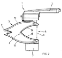
- Fig. 2
- eine Seitenansicht des Endpunktlagers gemäß
Fig. 1 .
- Fig. 1
- a spatial view of an endpoint bearing for two slats and
- Fig. 2
- a side view of the Endpunktlagers according to
Fig. 1 ,
Das Endpunktlager 1 für die Lattenenden eines Lattenrostes besteht im Wesentlichen aus einer Aufnahmekappe 2 für das Ende einer Latte eines Lastlattenrostes, einem darunter angeordneten Federelement 4 und einem wiederum darunter vorgesehenen Fußteil 3, welches in der Regel eine Bolzenaufnahme zur Befestigung auf einem in einem Längsholm eines Lattenrostes eingesetzten Bolzen aufweist.The
Das dargestellte Endpunktlager 1 weist zwei Aufnahmekappen 2 sowie für jede Aufnahmekappe 3 ein separates Federelement 4 auf sowie ein gemeinsames Fußteil 3 mit zwei Bolzenaufnahmen.The illustrated
Der Schutzumfang umfasst jedoch auch Endpunktlager 1 mit nur einer Aufnahmekappe 2 über einem Federelement 4 auf einem Fußteil 3 sowie auch entsprechend ausgebildete Endpunktlager 1 mit drei oder mehr Aufnahmekappen 2 und Federelementen 4.However, the scope of protection also includes end point bearing 1 with only one receiving
Die Fußteile 3 und die Federelemente 4 sind hier einstückig ausgebildet und die als Doppelkappe ausgebildete Aufnahmekappe 2 auf das Federelement 4 aufgerastet.The foot parts 3 and the spring elements 4 are integrally formed here and designed as a double
Ein Federelement 4 besteht im Wesentlichen aus einem sich vom Fußteil 3 in Richtung der Latte geschwungen nach innen und oben erstreckenden unteren Federstreifen 11 und einem sich von der Aufnahmekappe 2 in Richtung der Latte geschwungen nach innen und unten erstreckenden oberen Federstreifen 12 sowie aus einem horizontal mit seiner Spitze nach außen zum Holm gerichteten V-förmigen Profilelement 7, wobei diese Bauteile auf der nach innen, zur Mitte des Lattenrostes gerichteten Endbereichen der Federstreifen 11;12 und des Profilelementes 7 zu einem einteiligen Federprofil 5 miteinander verbunden sind.A spring element 4 consists essentially of a swinging from the foot part 3 in the direction of the bar inwardly and upwardly extending
Bei einer Belastung des Endpunktlagers 1 mit einer vertikalen Kraft verformt sich das schnabelförmige V-förmige Profilelement 7 derart, dass sich der "Schnabel" öffnet und sich nicht balgähnlich zusammenfaltet, wie dies zu vermuten wäre. Weiterhin liefert dieses Profilelement 7 einen wesentlichen Beitrag zur seitlichen Kippstabilität des Endpunktlagers 1.When a load on the end point bearing 1 with a vertical force, the beak-shaped V-
An dem einem dem zeichnerisch nicht dargestellten Holm zugewandten äußeren hinteren Ende des unteren Federstreifens 11 ist ein weiterer sich nach innen und oben erstreckender kürzerer unterer Stützfederstreifen 13 und am äußeren hinteren Ende des oberen Federstreifens 12 ein weiterer sich nach innen und unten geschwungen erstreckender kürzerer oberer Stützfederstreifen 14 angeordnet, deren nach innen gerichteten Enden stoffschlüssig miteinander verbunden sind, so dass sie gemeinsam ein inneres Stützfederprofil 6 bilden. Anstatt dieser dargestellten bogenförmigen Konstruktion könnte auch in dem Stützfederprofil 6 ein V-förmiges Profilelement 7 oder jedes andere denkbare Profil eingesetzt sein.At one of the drawers, not shown, the outer rear end of the
Das äußere Federprofil 5 und das innere Stützfederprofil 6 sind, wie in den Figuren dargestellt, zusammen mit dem Fußteil 3 einteilig aus einem Kunststoffspritzgussteil hergestellt. Das innere Stützfederprofil 6 könnte jedoch auch, wie zeichnerisch nicht dargestellt, über Rastelemente wahlfrei und austauschbar so ausgeführt sein, dass sich über eine Verwendung verschieden harter Stützfederprofile 6 eine einfache Härteeinstellung des Federelementes 4 und damit des Endpunktlagers 1 ergibt.The
Zeichnerisch ebenfalls nicht dargestellt sind den Federweg 9 der Federelemente 4 blockierende Härteverstellvorrichtungen, die sich in einen Zwischenraum 8 zwischen die oberen und unteren Federstreifen 11;12 und/ oder die Stützfederstreifen 13;14 erstrecken können, wobei diese Härteverstellvorrichtung sich entweder permanent dort hinein erstreckt oder aus einem Zwischenraum 10 zwischen benachbarten Federelementen 1 dort von der Seite her einschiebbar ist und die Bedienung durch einen Exzenter, Hebel, Schieber oder einen Drehknauf erfolgt, der an der Aufnahmekappe angeordnet und von oben betätigbar ist.Drawing also not shown are the
Claims (9)
Applications Claiming Priority (1)
| Application Number | Priority Date | Filing Date | Title |
|---|---|---|---|
| DE200820009628 DE202008009628U1 (en) | 2008-07-17 | 2008-07-17 | Endpoint bearing for battens of a slatted frame |
Publications (1)
| Publication Number | Publication Date |
|---|---|
| EP2145568A1 true EP2145568A1 (en) | 2010-01-20 |
Family
ID=39829862
Family Applications (1)
| Application Number | Title | Priority Date | Filing Date |
|---|---|---|---|
| EP09008754A Withdrawn EP2145568A1 (en) | 2008-07-17 | 2009-07-03 | Support for the slat end of a slatted frame |
Country Status (2)
| Country | Link |
|---|---|
| EP (1) | EP2145568A1 (en) |
| DE (1) | DE202008009628U1 (en) |
Families Citing this family (3)
| Publication number | Priority date | Publication date | Assignee | Title |
|---|---|---|---|---|
| AT509316B1 (en) * | 2010-09-23 | 2011-08-15 | Helmut Ofner | PLASTIC BODY, IN PARTICULAR FOR USE IN FOAM OR LATEX MATRICES OR THE LIKE |
| DE202013103212U1 (en) * | 2013-07-17 | 2013-09-18 | Lorenz Kunststofftechnik Gmbh | Spring strip bearing body of a slatted frame |
| CN107569000B (en) * | 2017-10-12 | 2023-08-25 | 南京理工大学 | Modularized independently adjustable spring bed frame |
Citations (9)
| Publication number | Priority date | Publication date | Assignee | Title |
|---|---|---|---|---|
| DE7034941U (en) * | 1970-09-21 | 1971-04-15 | Wagner Dietmar | SPRING SET FOR UPHOLSTERY. |
| DE19538082A1 (en) * | 1995-10-13 | 1997-04-17 | Roessle & Wanner Gmbh | Slat frame for e.g. bed |
| DE29611876U1 (en) * | 1996-07-09 | 1997-08-07 | Froli Kunststoffe Heinrich Fro | End spring for spring-loaded storage of slats on a slatted frame |
| EP1013200A1 (en) * | 1998-12-18 | 2000-06-28 | Ls Bedding | Device for mounting the slats of a slatted base in a springy way and at adjustable heights in relation to the bed frame |
| ES2171339A1 (en) * | 1999-07-09 | 2002-09-01 | Flex Equipos De Descanso Sa | Shock absorbing system for very wide bed bases, especially for slatted bed bases |
| DE202005019930U1 (en) | 2005-12-19 | 2006-02-23 | Hartmann, Siegbert | Underspringing system for beds or padded furniture, including mattress supporting element with upper, flexible engraved plate and lower, rigid base element, preferably of polypropylene |
| EP1632155A1 (en) * | 2004-09-04 | 2006-03-08 | Hansa-Holz-Kontor, Horst Rückle GmbH & Co. KG | Slatted bed base as frame |
| EP1472957B1 (en) | 2003-04-30 | 2006-10-11 | Tournadre SA Standard Gum | Suspension device for a double-slatted assembly |
| DE202006018923U1 (en) | 2006-12-13 | 2007-02-22 | Hartmann, Siegbert | Spring element for use in mattress or sofa, comprises cylindrical overall shape and circular bottom and top part |
-
2008
- 2008-07-17 DE DE200820009628 patent/DE202008009628U1/en not_active Expired - Lifetime
-
2009
- 2009-07-03 EP EP09008754A patent/EP2145568A1/en not_active Withdrawn
Patent Citations (9)
| Publication number | Priority date | Publication date | Assignee | Title |
|---|---|---|---|---|
| DE7034941U (en) * | 1970-09-21 | 1971-04-15 | Wagner Dietmar | SPRING SET FOR UPHOLSTERY. |
| DE19538082A1 (en) * | 1995-10-13 | 1997-04-17 | Roessle & Wanner Gmbh | Slat frame for e.g. bed |
| DE29611876U1 (en) * | 1996-07-09 | 1997-08-07 | Froli Kunststoffe Heinrich Fro | End spring for spring-loaded storage of slats on a slatted frame |
| EP1013200A1 (en) * | 1998-12-18 | 2000-06-28 | Ls Bedding | Device for mounting the slats of a slatted base in a springy way and at adjustable heights in relation to the bed frame |
| ES2171339A1 (en) * | 1999-07-09 | 2002-09-01 | Flex Equipos De Descanso Sa | Shock absorbing system for very wide bed bases, especially for slatted bed bases |
| EP1472957B1 (en) | 2003-04-30 | 2006-10-11 | Tournadre SA Standard Gum | Suspension device for a double-slatted assembly |
| EP1632155A1 (en) * | 2004-09-04 | 2006-03-08 | Hansa-Holz-Kontor, Horst Rückle GmbH & Co. KG | Slatted bed base as frame |
| DE202005019930U1 (en) | 2005-12-19 | 2006-02-23 | Hartmann, Siegbert | Underspringing system for beds or padded furniture, including mattress supporting element with upper, flexible engraved plate and lower, rigid base element, preferably of polypropylene |
| DE202006018923U1 (en) | 2006-12-13 | 2007-02-22 | Hartmann, Siegbert | Spring element for use in mattress or sofa, comprises cylindrical overall shape and circular bottom and top part |
Also Published As
| Publication number | Publication date |
|---|---|
| DE202008009628U1 (en) | 2008-10-09 |
Similar Documents
| Publication | Publication Date | Title |
|---|---|---|
| DE202006008525U1 (en) | Bed batten fitting C-shaped bed frame holding profile and side socket section | |
| EP1649786B1 (en) | Fitting for hinging the slat support members of an undermattress | |
| DE202015101436U1 (en) | Height-adjustable side panel for a nursing bed | |
| EP1155643B1 (en) | Supporting device | |
| WO2010012333A1 (en) | Slatted frame for a bed or similar reclining furniture | |
| AT390722B (en) | USE FOR A LOUNGE FURNITURE | |
| EP2145568A1 (en) | Support for the slat end of a slatted frame | |
| DE202019102922U1 (en) | Fold-out sofa | |
| EP2792278A1 (en) | End point bearing of transverse slats of a mattress bed base | |
| EP1754429A1 (en) | Spring arrangement for supporting a mattress | |
| DE202004005598U1 (en) | Storage for slats of bed slatted frames | |
| DE202015101963U1 (en) | slatted | |
| EP2679118B1 (en) | Mattress for seat and/or reclining furniture, particularly for beds | |
| DE202008016707U1 (en) | seating | |
| DE10307738B4 (en) | Tilt adjustment device for at least part of a lying or sitting area | |
| EP3167766B1 (en) | Suspension spring for a seat or bed support and support having at least one such suspension spring | |
| DE102015106048A1 (en) | slatted | |
| DE202007004007U1 (en) | Adjustable single spring is used to provide support for a chair or platform has a leaf spring form | |
| AT517897B1 (en) | Spring strip for a seat or Liegemöbelunterfederung and spring suspension with at least one such spring bar | |
| AT517575B1 (en) | Adjustable backrest part | |
| DE202017102905U1 (en) | slatted | |
| EP2078476A1 (en) | Motorised adjustable frame for a bed, a berth, or similar | |
| EP3170428B1 (en) | Spring module and suspension with such spring modules | |
| DE202015101188U1 (en) | Spring strip for a Matratzenunterfederung and mattress suspension with at least one such spring bar | |
| EP3069634B1 (en) | Spring contact for seat or bed furniture spring support comprising same |
Legal Events
| Date | Code | Title | Description |
|---|---|---|---|
| PUAI | Public reference made under article 153(3) epc to a published international application that has entered the european phase |
Free format text: ORIGINAL CODE: 0009012 |
|
| AK | Designated contracting states |
Kind code of ref document: A1 Designated state(s): AT BE BG CH CY CZ DE DK EE ES FI FR GB GR HR HU IE IS IT LI LT LU LV MC MK MT NL NO PL PT RO SE SI SK SM TR |
|
| AX | Request for extension of the european patent |
Extension state: AL BA RS |
|
| 17P | Request for examination filed |
Effective date: 20100625 |
|
| 17Q | First examination report despatched |
Effective date: 20100726 |
|
| STAA | Information on the status of an ep patent application or granted ep patent |
Free format text: STATUS: THE APPLICATION IS DEEMED TO BE WITHDRAWN |
|
| 18D | Application deemed to be withdrawn |
Effective date: 20140201 |