EP2145199B1 - Magnetresonanzgerät und verfahren für propeller-mri - Google Patents
Magnetresonanzgerät und verfahren für propeller-mri Download PDFInfo
- Publication number
- EP2145199B1 EP2145199B1 EP08737949.1A EP08737949A EP2145199B1 EP 2145199 B1 EP2145199 B1 EP 2145199B1 EP 08737949 A EP08737949 A EP 08737949A EP 2145199 B1 EP2145199 B1 EP 2145199B1
- Authority
- EP
- European Patent Office
- Prior art keywords
- space
- angle
- blades
- magnetic field
- signals
- Prior art date
- Legal status (The legal status is an assumption and is not a legal conclusion. Google has not performed a legal analysis and makes no representation as to the accuracy of the status listed.)
- Not-in-force
Links
Images

Classifications
-
- G—PHYSICS
- G01—MEASURING; TESTING
- G01R—MEASURING ELECTRIC VARIABLES; MEASURING MAGNETIC VARIABLES
- G01R33/00—Arrangements or instruments for measuring magnetic variables
- G01R33/20—Arrangements or instruments for measuring magnetic variables involving magnetic resonance
- G01R33/44—Arrangements or instruments for measuring magnetic variables involving magnetic resonance using nuclear magnetic resonance [NMR]
- G01R33/48—NMR imaging systems
- G01R33/4818—MR characterised by data acquisition along a specific k-space trajectory or by the temporal order of k-space coverage, e.g. centric or segmented coverage of k-space
- G01R33/4824—MR characterised by data acquisition along a specific k-space trajectory or by the temporal order of k-space coverage, e.g. centric or segmented coverage of k-space using a non-Cartesian trajectory
-
- G—PHYSICS
- G01—MEASURING; TESTING
- G01R—MEASURING ELECTRIC VARIABLES; MEASURING MAGNETIC VARIABLES
- G01R33/00—Arrangements or instruments for measuring magnetic variables
- G01R33/20—Arrangements or instruments for measuring magnetic variables involving magnetic resonance
- G01R33/44—Arrangements or instruments for measuring magnetic variables involving magnetic resonance using nuclear magnetic resonance [NMR]
- G01R33/48—NMR imaging systems
- G01R33/4818—MR characterised by data acquisition along a specific k-space trajectory or by the temporal order of k-space coverage, e.g. centric or segmented coverage of k-space
- G01R33/4824—MR characterised by data acquisition along a specific k-space trajectory or by the temporal order of k-space coverage, e.g. centric or segmented coverage of k-space using a non-Cartesian trajectory
- G01R33/4826—MR characterised by data acquisition along a specific k-space trajectory or by the temporal order of k-space coverage, e.g. centric or segmented coverage of k-space using a non-Cartesian trajectory in three dimensions
-
- G—PHYSICS
- G01—MEASURING; TESTING
- G01R—MEASURING ELECTRIC VARIABLES; MEASURING MAGNETIC VARIABLES
- G01R33/00—Arrangements or instruments for measuring magnetic variables
- G01R33/20—Arrangements or instruments for measuring magnetic variables involving magnetic resonance
- G01R33/44—Arrangements or instruments for measuring magnetic variables involving magnetic resonance using nuclear magnetic resonance [NMR]
- G01R33/48—NMR imaging systems
- G01R33/483—NMR imaging systems with selection of signals or spectra from particular regions of the volume, e.g. in vivo spectroscopy
- G01R33/4833—NMR imaging systems with selection of signals or spectra from particular regions of the volume, e.g. in vivo spectroscopy using spatially selective excitation of the volume of interest, e.g. selecting non-orthogonal or inclined slices
- G01R33/4835—NMR imaging systems with selection of signals or spectra from particular regions of the volume, e.g. in vivo spectroscopy using spatially selective excitation of the volume of interest, e.g. selecting non-orthogonal or inclined slices of multiple slices
-
- G—PHYSICS
- G01—MEASURING; TESTING
- G01R—MEASURING ELECTRIC VARIABLES; MEASURING MAGNETIC VARIABLES
- G01R33/00—Arrangements or instruments for measuring magnetic variables
- G01R33/20—Arrangements or instruments for measuring magnetic variables involving magnetic resonance
- G01R33/44—Arrangements or instruments for measuring magnetic variables involving magnetic resonance using nuclear magnetic resonance [NMR]
- G01R33/48—NMR imaging systems
- G01R33/54—Signal processing systems, e.g. using pulse sequences ; Generation or control of pulse sequences; Operator console
- G01R33/56—Image enhancement or correction, e.g. subtraction or averaging techniques, e.g. improvement of signal-to-noise ratio and resolution
- G01R33/561—Image enhancement or correction, e.g. subtraction or averaging techniques, e.g. improvement of signal-to-noise ratio and resolution by reduction of the scanning time, i.e. fast acquiring systems, e.g. using echo-planar pulse sequences
-
- G—PHYSICS
- G01—MEASURING; TESTING
- G01R—MEASURING ELECTRIC VARIABLES; MEASURING MAGNETIC VARIABLES
- G01R33/00—Arrangements or instruments for measuring magnetic variables
- G01R33/20—Arrangements or instruments for measuring magnetic variables involving magnetic resonance
- G01R33/44—Arrangements or instruments for measuring magnetic variables involving magnetic resonance using nuclear magnetic resonance [NMR]
- G01R33/48—NMR imaging systems
- G01R33/54—Signal processing systems, e.g. using pulse sequences ; Generation or control of pulse sequences; Operator console
- G01R33/56—Image enhancement or correction, e.g. subtraction or averaging techniques, e.g. improvement of signal-to-noise ratio and resolution
- G01R33/561—Image enhancement or correction, e.g. subtraction or averaging techniques, e.g. improvement of signal-to-noise ratio and resolution by reduction of the scanning time, i.e. fast acquiring systems, e.g. using echo-planar pulse sequences
- G01R33/5615—Echo train techniques involving acquiring plural, differently encoded, echo signals after one RF excitation, e.g. using gradient refocusing in echo planar imaging [EPI], RF refocusing in rapid acquisition with relaxation enhancement [RARE] or using both RF and gradient refocusing in gradient and spin echo imaging [GRASE]
-
- G—PHYSICS
- G01—MEASURING; TESTING
- G01R—MEASURING ELECTRIC VARIABLES; MEASURING MAGNETIC VARIABLES
- G01R33/00—Arrangements or instruments for measuring magnetic variables
- G01R33/20—Arrangements or instruments for measuring magnetic variables involving magnetic resonance
- G01R33/44—Arrangements or instruments for measuring magnetic variables involving magnetic resonance using nuclear magnetic resonance [NMR]
- G01R33/48—NMR imaging systems
- G01R33/54—Signal processing systems, e.g. using pulse sequences ; Generation or control of pulse sequences; Operator console
- G01R33/56—Image enhancement or correction, e.g. subtraction or averaging techniques, e.g. improvement of signal-to-noise ratio and resolution
- G01R33/561—Image enhancement or correction, e.g. subtraction or averaging techniques, e.g. improvement of signal-to-noise ratio and resolution by reduction of the scanning time, i.e. fast acquiring systems, e.g. using echo-planar pulse sequences
- G01R33/5615—Echo train techniques involving acquiring plural, differently encoded, echo signals after one RF excitation, e.g. using gradient refocusing in echo planar imaging [EPI], RF refocusing in rapid acquisition with relaxation enhancement [RARE] or using both RF and gradient refocusing in gradient and spin echo imaging [GRASE]
- G01R33/5617—Echo train techniques involving acquiring plural, differently encoded, echo signals after one RF excitation, e.g. using gradient refocusing in echo planar imaging [EPI], RF refocusing in rapid acquisition with relaxation enhancement [RARE] or using both RF and gradient refocusing in gradient and spin echo imaging [GRASE] using RF refocusing, e.g. RARE
-
- G—PHYSICS
- G01—MEASURING; TESTING
- G01R—MEASURING ELECTRIC VARIABLES; MEASURING MAGNETIC VARIABLES
- G01R33/00—Arrangements or instruments for measuring magnetic variables
- G01R33/20—Arrangements or instruments for measuring magnetic variables involving magnetic resonance
- G01R33/44—Arrangements or instruments for measuring magnetic variables involving magnetic resonance using nuclear magnetic resonance [NMR]
- G01R33/48—NMR imaging systems
- G01R33/54—Signal processing systems, e.g. using pulse sequences ; Generation or control of pulse sequences; Operator console
- G01R33/56—Image enhancement or correction, e.g. subtraction or averaging techniques, e.g. improvement of signal-to-noise ratio and resolution
- G01R33/565—Correction of image distortions, e.g. due to magnetic field inhomogeneities
- G01R33/56509—Correction of image distortions, e.g. due to magnetic field inhomogeneities due to motion, displacement or flow, e.g. gradient moment nulling
-
- G—PHYSICS
- G01—MEASURING; TESTING
- G01R—MEASURING ELECTRIC VARIABLES; MEASURING MAGNETIC VARIABLES
- G01R33/00—Arrangements or instruments for measuring magnetic variables
- G01R33/20—Arrangements or instruments for measuring magnetic variables involving magnetic resonance
- G01R33/44—Arrangements or instruments for measuring magnetic variables involving magnetic resonance using nuclear magnetic resonance [NMR]
- G01R33/48—NMR imaging systems
- G01R33/54—Signal processing systems, e.g. using pulse sequences ; Generation or control of pulse sequences; Operator console
- G01R33/56—Image enhancement or correction, e.g. subtraction or averaging techniques, e.g. improvement of signal-to-noise ratio and resolution
- G01R33/567—Image enhancement or correction, e.g. subtraction or averaging techniques, e.g. improvement of signal-to-noise ratio and resolution gated by physiological signals, i.e. synchronization of acquired MR data with periodical motion of an object of interest, e.g. monitoring or triggering system for cardiac or respiratory gating
- G01R33/5676—Gating or triggering based on an MR signal, e.g. involving one or more navigator echoes for motion monitoring and correction
Definitions
- the invention relates to a device for magnetic resonance imaging (MRI) of a body placed in an examination volume.
- MRI magnetic resonance imaging
- the invention relates to a method for MRI and to a computer program for a magnetic resonance (MR) device.
- MR magnetic resonance
- MRI In MRI, pulse sequences consisting of RF pulses and switched magnetic field gradients are applied to an object (a patient) placed in a homogeneous magnetic field within an examination volume of an MR device. In this way, MR signals are generated, which are scanned by means of radio frequency (RF) receiving antennas in order to obtain information about the object and to reconstruct images thereof.
- RF radio frequency
- the pulse sequence which is applied during an MRI scan, plays a significant role in the determination of the characteristics of the reconstructed image, such as location and orientation in the object, dimensions, resolution, signal-to-noise ratio, contrast, sensitivity for movements, et cetera.
- An operator of an MRI device has to choose the appropriate sequence and has to adjust and optimize its parameters for the respective application.
- MR signals are acquired in k-space in N strips, each consisting of L parallel lines, corresponding to the L lowest frequency phase-encoding lines in a Cartesian k-space sampling scheme.
- One essential characteristic of PROPELLER is that a central circular portion in k-space, having a diameter L , is acquired for each k-space blade. This central portion can be used to reconstruct a low-resolution image for each k-space blade. These low-resolution images, or their k-space representations, are compared to each other to remove in-plane displacements and phase errors, which are due to patient motion.
- a suitable technique such as cross-correlation is employed to determine which k-space blades were acquired with significant through-plane displacement.
- the MR data from k-space blades with the least amount of through-plane motion are preferentially used in regions in which the k-space blades overlap, so that artifacts arising from through-plane motion are reduced.
- the PROPELLER technique makes use of oversampling in the central portion of k-space in order to obtain an MR image acquisition technique that is robust with respect to motion of the examined patient during MR signal acquisition.
- Ji et al. (IEEE EMBS, p. 478-481, 2003 ) describe an improved MRI approach for dynamic contrast-enhanced imaging of tumors.
- a new data acquisition scheme is employed which is principally based on PROPELLER.
- the k-space blades are rotated in a special order so that two consecutively acquired blades cover k-space in orthogonal directions.
- US 2007/0001672 A1 discloses a PROPELLER-based MRI method, wherein a high-pass convolution of each acquired k-space blade with a reference k-space blade is determined and converted to a ⁇ function. In-plane motion of the imaged object during data acquisition is deduced from the ⁇ function.
- Pipe et al. (Proc. ISMRM, p. 743, 2001 ) likewise propose an improved in-plane motion correction scheme for PROPELLER MRI.
- a single k-space blade is initially chosen as a reference blade. All other acquired k-space blades are translated to the location of the reference blade and an averaged image is calculated. In a second iteration, all k-space blades are translated to match the averaged image.
- Arfanakis et al. propose to reduce the scan time for PROPELLER MRI by means of undersampling. Undersampling is performed by removing whole k-space blades from a conventional PROPELLER sampling scheme, by using asymmetric k-space blades and by taking advantage of Hermitian symmetries to fill-in missing data. Imaging time is significantly reduced in this way without causing image artifacts.
- One problem of the known PROPELLER concept is that a complete rejection of motion-corrupted k-space blades results in undersampling of the peripheral k-space regions and, hence, in a potentially degraded image quality.
- Another problem associated with multi-slice PROPELLER imaging is that individual slices from a multi-slice PROPELLER acquisition may be misaligned.
- PROPELLER cross-cor relates repeatedly measured MR signals in the central k-space as a reference for motion correction.
- a reference is chosen showing the most similarity to the central k-space data of the other blades.
- the reference data chosen in accordance with PROPELLER is thus not an absolute but a relative reference, which may cause misalignment of the individual slices.
- a retrospective alignment of the slices of a multi-slice MR scan is possible in principle, provided that adjacent slices show substantial similarity. This pre-requisite is questionable in general, however.
- the known PROPELLER imaging method requires a weighting of the acquired k-space samples. This is usually referred to as sampling density compensation.
- sampling density compensation To compute the weighting factors, an iterative approach is commonly taken.
- the weighting also permits a prioritization of MR signals according to various criteria, such as correlation measures of the cross-correlated k-space blades, in order to achieve the above-mentioned reduction of motion-induced image artifacts.
- This prioritization can be applied in k-space areas that are more densely sampled than actually required to support the selected field of view.
- a drawback of the known technique is that the usually taken iterative approach for computing the weighting factors is slow and sporadically instable, especially if a strong contrast weighting is applied
- an MR device for MRI of a body placed in an examination volume which comprises means for establishing a substantially homogeneous main magnetic field in the examination volume, means for generating switched magnetic field gradients superimposed upon the main magnetic field, means for radiating RF pulses towards the body, control means for controlling the generation of the magnetic field gradients and the RF pulses, means for receiving and sampling MR signals, and reconstruction means for forming MR images from the signal samples.
- the invention proposes that the MR device is arranged to
- the invention is based on the recognition of the fact that a regular angular undersampling produces only minimal image artifacts. Hence, the least artifacts can be expected if, in accordance with the invention, motion-corrupted k-space blades are distributed as uniformly as possible over the circle spanned by the rotated k-space blades. Since the angle is incremented according to the invention by an angle being approximately equal to golden angle or the half golden angle, an interleaved arrangement of successively acquired k-space blades is achieved.
- the regular angular undersampling proposed by the invention is more robust for image reconstruction than the omission of several motion-corrupted adjacent k-space blades which is characteristic for the conventional linear order of blades.
- the so-called Golden Angle principle is applied to PROPELLER MRI to generate an interleaved spatiotemporal order of k-space blades.
- the Golden Angle principle applied to PROPELLER MRI according to the invention enables a particularly isotropic distribution of corrupted k-space blades over the circle spanned by the rotated blades and, thus, a minimization of motion-induced artifacts in the finally reconstructed MR image.
- By incrementing the rotation angle by the Golden Angle an isotropic, increasingly dense angular coverage of the circle is achieved.
- For the diametric PROPELLER blades only a semicircle has to be considered, which results in a rotation increment of the half Golden Angle.
- the blade arrangement within the circle spanned by the k-space blades is slightly asymmetric.
- the number of k-space blades is fixed, making a symmetric arrangement of blades more preferable.
- the function f ( i ) is chosen such that the above-described interleaved arrangement results, wherein the angles ⁇ ( i ) approximate the Golden Angle (or the half Golden Angle) as closely as possible.
- the invention not only relates to a device but also to a method for MRI of at least a portion of a body placed in an examination volume of an MR device.
- a computer program adapted for carrying out the imaging procedure of the invention can advantageously be implemented on any common computer hardware, which is presently in clinical use for the control of magnetic resonance scanners.
- the computer program can be provided on suitable data carriers, such as CD-ROM or diskette. Alternatively, it can also be downloaded by a user from an Internet server.
- the apparatus 1 comprises a set of main magnetic coils 2 for generating a stationary and homogeneous main magnetic field and three sets of gradient coils 3, 4 and 5 for superimposing additional magnetic fields with controllable strength and having a gradient in a selected direction.
- the direction of the main magnetic field is labelled the z-direction, the two directions perpendicular thereto the x- and y-directions.
- the gradient coils 3, 4 and 5 are energized via a power supply 11.
- the imaging device 1 further comprises an RF transmit antenna 6 for emitting RF pulses to a body 7.
- the antenna 6 is coupled to a modulator 9 for generating and modulating the RF pulses.
- a receiver for receiving the MR signals can be identical to the transmit antenna 6 or be separate. If the transmit antenna 6 and receiver are physically the same antenna as shown in Fig. 1 , a send-receive switch 8 is arranged to separate the received signals from the pulses to be emitted.
- the received MR signals are input to a demodulator 10.
- the send-receive switch 8, the modulator 9, and the power supply 11 for the gradient coils 3, 4 and 5 are controlled by a control system 12.
- Control system 12 controls the phases and amplitudes of the RF signals fed to the antenna 6.
- the control system 12 is usually a microcomputer with a memory and a program control.
- the demodulator 10 is coupled to reconstruction means 14, for example a computer, for transformation of the received signals into images that can be made visible, for example, on a visual display unit 15.
- reconstruction means 14 for example a computer
- the MR device 1 comprises a programming for executing an MRI PROPELLER scheme in the above-described manner.
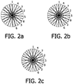
- Fig. 2 illustrates the k-space sampling of PROPELLER MRI according to the invention.
- Eight k-space PROPELLER blades are acquired. The blades are rotated about the center of k-space, so that the total acquired MR data set approximately spans a circle in k-space.
- the arrows shown in Fig. 2 indicate the directions of the readout magnetic field gradients generated for the respective k-space blades.
- the rotation angle of the successively acquired k-space blades is incremented by the half Golden angle, which is approximately 68,75°.
- An isotropic, increasingly dense angular coverage of the circle is achieved in this way, which is also used e.g. by nature for the arrangement of leaves on a plant.
- the Golden Angle increment generates the interleaved arrangement of successive PROPELLER blades shown in Fig. 2a .
- motion-corrupted k-space blades are distributed uniformly over the circle spanned by the PROPELLER acquisition.
- Image artifacts are reduced as compared to conventional PROPELLER imaging, in which a linear order of consecutive k-space blades is applied.
- the rotation angle increment can be the half Golden Angle instead of the full Golden Angle.
- the (half) Golden Angle increment results in an infinite sequence period and in a correspondingly asymmetric arrangement of the PROPELLER blades in k-space as can be seen in Fig.
- f ( i ) f ( i ) ⁇ 180° / N , wherein f ( i ) represents a function that maps the index i to an integral number between 0 and N - 1 such that the desired order is obtained.
- f ( i ) can be tabulated as follows: i 1 2 3 4 5 6 7 8 f ( i ) 0 3 6 1 4 7 2 5
- the readout gradient rotates about 180° during one acquisition in this case.
Landscapes
- Physics & Mathematics (AREA)
- High Energy & Nuclear Physics (AREA)
- Condensed Matter Physics & Semiconductors (AREA)
- General Physics & Mathematics (AREA)
- Health & Medical Sciences (AREA)
- General Health & Medical Sciences (AREA)
- Nuclear Medicine, Radiotherapy & Molecular Imaging (AREA)
- Radiology & Medical Imaging (AREA)
- Engineering & Computer Science (AREA)
- Signal Processing (AREA)
- Spectroscopy & Molecular Physics (AREA)
- Optics & Photonics (AREA)
- Magnetic Resonance Imaging Apparatus (AREA)
Claims (4)
- Vorrichtung zur MR-Bildgebung eines in einem Untersuchungsvolumen angeordneten Körpers (7), wobei die Vorrichtung (1) umfasstMittel (2) zum Ausbilden eines im Wesentlichen homogenen Hauptmagnetfeldes im Untersuchungsvolumen,Mittel (3, 4, 5) zum Erzeugen geschalteter Magnetfeldgradienten, die dem Hauptmagnetfeld überlagert sind,Mittel (6) zum Abstrahlen von RF-Pulsen in Richtung des Körpers (7),Steuerungsmittel (12) zur Steuerung der Erzeugung der Magnetfeldgradienten und der RF-Pulse,Mittel (10) zum Empfangen und Abtasten von MR-Signalen, undRekonstruktionsmittel (14) zur Bildung von MR-Bildern aus den Signalabtastungen,wobei die Vorrichtung (1) dazu eingerichtet ista) eine Reihe von MR-Signalen durch Beaufschlagen mindestens eines Teils des Körpers (7) mit einer MR-Bildgebungssequenz aus mindestens einem RF-Puls und geschalteten Magnetfeldgradienten zu erzeugen,b) eine Vielzahl von k-Raum-Blades gemäß dem PROPELLER-Schema zu erfassen, wobei die k-Raum-Blades um ein Zentrum eines k-Raums rotiert werden, wobei der Rotationswinkel von aufeinanderfolgend erfassten k-Raum-Blades während der MR-Signalerfassung um einen Winkel erhöht wird, der ungefähr gleich dem goldenen Winkel von 137,51° oder dem halben goldenen Winkel von 68,75° ist, undc) ein MR-Bild aus den erfassten MR-Signalen zu rekonstruieren.
- Vorrichtung nach Anspruch 1, wobei die Vorrichtung (1) weiter dazu eingerichtet ist, den Rotationswinkel gemäß der Formel ϕ(i) = f(i)·180°/N oder ϕ(i) = f(i)·180°·(1 + 1/N) zu wählen, wobei i = 1,2,...N einen Index der aufeinanderfolgend erfassten k-Raum-Blades repräsentiert, und f(i) eine Funktion repräsentiert, die den Index i auf eine ganze Zahl zwischen 0 und N - 1 so abbildet, dass das Rotationswinkelinkrement ϕ(i + 1) - ϕ(i) ungefähr gleich dem goldenen Winkel von 137,51° oder dem halben goldenen Winkel von 68,75° und größer als 180°/N ist.
- Verfahren zur MR-Bildgebung mindestens eines Teils eines in einem Untersuchungsvolumen einer MR-Vorrichtung angeordneten Körpers, wobei das Verfahren die folgenden Schritte umfasst:a) Erzeugen einer Reihe von MR-Signalen durch Beaufschlagen mindestens eines Teils des Körpers mit einer MR-Bildgebungssequenz aus mindestens einem RF-Puls und geschalteten Magnetfeldgradienten,b) Erfassen einer Vielzahl von k-Raum-Blades gemäß dem PROPELLER-Schema, wobei die k-Raum-Blades um ein Zentrum eines k-Raums rotiert werden, wobei der Rotationswinkel von aufeinanderfolgend erfassten k-Raum-Blades während der MR-Signalerfassung um einen Winkel erhöht wird, der ungefähr gleich dem goldenen Winkel von 137,51° oder dem halben goldenen Winkel von 68,75° ist, undc) Rekonstruieren eines MR-Bildes aus den erfassten MR-Signalen.
- Computerprogramm für eine MR-Vorrichtung, wobei das Programm Anweisungen zur Steuerung der MR-Vorrichtung umfasst, sodass das Verfahren nach Anspruch 3 ausgeführt wird.
Priority Applications (2)
| Application Number | Priority Date | Filing Date | Title |
|---|---|---|---|
| EP08737949.1A EP2145199B1 (de) | 2007-04-27 | 2008-04-22 | Magnetresonanzgerät und verfahren für propeller-mri |
| EP14172087.0A EP2806284B1 (de) | 2007-04-27 | 2008-04-22 | Magnetresonanzvorrichtung und -verfahren für propeller mri |
Applications Claiming Priority (3)
| Application Number | Priority Date | Filing Date | Title |
|---|---|---|---|
| EP07107078 | 2007-04-27 | ||
| EP08737949.1A EP2145199B1 (de) | 2007-04-27 | 2008-04-22 | Magnetresonanzgerät und verfahren für propeller-mri |
| PCT/IB2008/051544 WO2008132659A2 (en) | 2007-04-27 | 2008-04-22 | Magnetic resonance device and method for propeller mri |
Related Child Applications (2)
| Application Number | Title | Priority Date | Filing Date |
|---|---|---|---|
| EP14172087.0A Division EP2806284B1 (de) | 2007-04-27 | 2008-04-22 | Magnetresonanzvorrichtung und -verfahren für propeller mri |
| EP14172087.0A Division-Into EP2806284B1 (de) | 2007-04-27 | 2008-04-22 | Magnetresonanzvorrichtung und -verfahren für propeller mri |
Publications (2)
| Publication Number | Publication Date |
|---|---|
| EP2145199A2 EP2145199A2 (de) | 2010-01-20 |
| EP2145199B1 true EP2145199B1 (de) | 2018-12-12 |
Family
ID=39712642
Family Applications (2)
| Application Number | Title | Priority Date | Filing Date |
|---|---|---|---|
| EP08737949.1A Not-in-force EP2145199B1 (de) | 2007-04-27 | 2008-04-22 | Magnetresonanzgerät und verfahren für propeller-mri |
| EP14172087.0A Active EP2806284B1 (de) | 2007-04-27 | 2008-04-22 | Magnetresonanzvorrichtung und -verfahren für propeller mri |
Family Applications After (1)
| Application Number | Title | Priority Date | Filing Date |
|---|---|---|---|
| EP14172087.0A Active EP2806284B1 (de) | 2007-04-27 | 2008-04-22 | Magnetresonanzvorrichtung und -verfahren für propeller mri |
Country Status (4)
| Country | Link |
|---|---|
| EP (2) | EP2145199B1 (de) |
| JP (3) | JP5781760B2 (de) |
| CN (1) | CN101669038B (de) |
| WO (1) | WO2008132659A2 (de) |
Families Citing this family (33)
| Publication number | Priority date | Publication date | Assignee | Title |
|---|---|---|---|---|
| EP2145199B1 (de) * | 2007-04-27 | 2018-12-12 | Koninklijke Philips N.V. | Magnetresonanzgerät und verfahren für propeller-mri |
| JP5613065B2 (ja) | 2010-01-21 | 2014-10-22 | 株式会社東芝 | 磁気共鳴イメージング装置 |
| EP2623028A4 (de) * | 2010-09-27 | 2017-10-25 | Hitachi, Ltd. | Magnetresonanztomographievorrichtung und magnetresonanztomographieverfahren |
| WO2012160971A1 (ja) * | 2011-05-20 | 2012-11-29 | 株式会社 日立メディコ | 磁気共鳴イメージング装置、及び再構成画像取得方法 |
| US10429469B2 (en) * | 2012-04-11 | 2019-10-01 | Dignity Health | System and method for magnetic resonance imaging using three-dimensional, distributed, non-Cartesian sampling trajectories |
| EP2839433B1 (de) * | 2012-04-19 | 2024-03-13 | New York University | System, verfahren und computermedium zur dynamischen magnetresonanzabbildung mit hoher beschleunigung unter verwendung radialer abtastung im goldenen winkel |
| EP2893363B1 (de) * | 2012-09-04 | 2020-08-19 | Koninklijke Philips N.V. | Propeller mit wasser-fett-trennung nach dixon |
| CN103777162B (zh) * | 2012-10-19 | 2018-06-05 | 上海联影医疗科技有限公司 | 磁共振成像k空间运动伪影矫正并行采集重建方法 |
| KR101447547B1 (ko) * | 2012-11-23 | 2014-10-06 | 삼성전자주식회사 | 자기 공명 영상 촬상 방법 및 장치 |
| DE102013201616B3 (de) * | 2013-01-31 | 2014-07-17 | Siemens Aktiengesellschaft | TSE-basierte, gegen lokale B0-Feldvariationen unempfindliche MR-Mulitschicht-Anregung |
| DE102013205576B4 (de) * | 2013-03-28 | 2024-05-23 | Siemens Healthineers Ag | Verfahren zum Erzeugen einer Bewegungskorrektur für PET-Daten, Verfahren zum Erzeugen von PET-Bildern sowie entsprechend ausgestaltete MR-Anlage und PET-Anlage, Computerprogramm und elektronisch lesbarer Datenträger |
| US9933505B2 (en) | 2013-04-03 | 2018-04-03 | Dignity Health | System and method for motion correction in magnetic resonance imaging |
| CN104122521B (zh) * | 2013-04-27 | 2017-12-22 | 上海联影医疗科技有限公司 | k空间运动伪影矫正方法及装置 |
| US10132889B2 (en) | 2013-05-22 | 2018-11-20 | General Electric Company | System and method for reducing acoustic noise level in MR imaging |
| DE102013210947B4 (de) * | 2013-06-12 | 2019-01-10 | Siemens Healthcare Gmbh | Radiale MR-Abtastung unter Verwendung des Goldenen Winkels |
| US10288705B2 (en) | 2013-10-08 | 2019-05-14 | Koninklijke Philips N.V. | Corrected multiple-slice magnetic resonance imaging |
| US9788761B2 (en) * | 2014-02-27 | 2017-10-17 | Toshiba Medical Systems Corporation | Motion correction for magnetic resonance angiography (MRA) with 3D radial acquisitions |
| DE102014209437B3 (de) * | 2014-05-19 | 2015-10-22 | Sirona Dental Systems Gmbh | Verfahren zur Erzeugung magnetresonanztomographischer Aufnahmen von zyklischer Bewegung |
| DE102014220328B3 (de) * | 2014-10-07 | 2015-08-27 | Sirona Dental Systems Gmbh | Erstellung einer MRT-Aufnahme |
| RU2707661C2 (ru) * | 2014-10-10 | 2019-11-28 | Конинклейке Филипс Н.В. | Мр (магнитно-резонансная) томография методом propeller c подавлением артефактов |
| US9983283B2 (en) * | 2015-03-16 | 2018-05-29 | Toshiba Medical Systems Corporation | Accelerated MRI using radial strips and undersampling of k-space |
| WO2017009391A1 (en) * | 2015-07-15 | 2017-01-19 | Koninklijke Philips N.V. | Mr imaging with motion detection |
| KR101733801B1 (ko) | 2015-12-17 | 2017-05-10 | 삼성전자주식회사 | 자기 공명 영상 장치 및 그 방법 |
| CN107843862B (zh) * | 2016-09-20 | 2021-04-23 | 奥泰医疗系统有限责任公司 | 一种propeller技术中参考位置图像的非迭代生成方法 |
| CN106264530B (zh) * | 2016-11-04 | 2019-08-23 | 深圳先进技术研究院 | 用于三维动态磁共振成像的笛卡尔k空间采集方法和系统 |
| CN106264529B (zh) * | 2016-11-04 | 2019-08-23 | 深圳先进技术研究院 | 用于三维动态磁共振成像的圆柱形k空间采集方法和系统 |
| CN109983358B (zh) * | 2016-11-24 | 2021-10-26 | 皇家飞利浦有限公司 | Propeller mr成像 |
| CN106680748B (zh) * | 2016-12-30 | 2019-10-08 | 上海联影医疗科技有限公司 | 磁共振图像获取方法及磁共振系统 |
| CN107037385B (zh) * | 2017-05-22 | 2019-10-01 | 上海培云教育科技有限公司 | 数字mri图谱的构建方法及设备 |
| CN107219481B (zh) * | 2017-05-26 | 2019-09-27 | 深圳先进技术研究院 | 一种通用的三维欠采样轨迹设计方法 |
| CN108577841B (zh) * | 2018-02-23 | 2021-09-10 | 奥泰医疗系统有限责任公司 | 一种propeller技术中抑制非刚性运动的权重计算方法 |
| CN111239658B (zh) * | 2020-02-19 | 2022-07-19 | 上海康达卡勒幅医疗科技有限公司 | 一种减小propeller序列伪影的方法 |
| US11550013B2 (en) * | 2020-09-30 | 2023-01-10 | GE Precision Healthcare LLC | Systems and methods of silent multi-gradient echo dynamic magnetic resonance imaging |
Family Cites Families (8)
| Publication number | Priority date | Publication date | Assignee | Title |
|---|---|---|---|---|
| DE4317028C3 (de) * | 1993-05-21 | 2000-06-29 | Martin Busch | Verfahren zur Akquisition und Auswertung von Daten in einem Kernspin-Tomographen |
| DE10211485A1 (de) * | 2002-03-15 | 2003-09-25 | Philips Intellectual Property | Verfahren zur Bestimmung einer Objektfunktion |
| AU2003260846A1 (en) * | 2002-10-01 | 2004-04-23 | Koninklijke Philips Electronics N.V. | A method for k-space data acquisition and mri device |
| WO2005023108A1 (ja) * | 2003-09-05 | 2005-03-17 | Hitachi Medical Corporation | 磁気共鳴イメージング装置 |
| US7176684B2 (en) * | 2005-06-29 | 2007-02-13 | General Electric Company | Method and system of determining in-plane motion in propeller data |
| JP5179182B2 (ja) * | 2005-07-27 | 2013-04-10 | 株式会社日立メディコ | 磁気共鳴イメージング装置 |
| DE102006033862B3 (de) * | 2006-07-21 | 2007-12-06 | Siemens Ag | Verfahren zur dynamischen Magnet-Resonanz-Bildgebung sowie Magnet-Resonanz-Gerät |
| EP2145199B1 (de) * | 2007-04-27 | 2018-12-12 | Koninklijke Philips N.V. | Magnetresonanzgerät und verfahren für propeller-mri |
-
2008
- 2008-04-22 EP EP08737949.1A patent/EP2145199B1/de not_active Not-in-force
- 2008-04-22 EP EP14172087.0A patent/EP2806284B1/de active Active
- 2008-04-22 WO PCT/IB2008/051544 patent/WO2008132659A2/en not_active Ceased
- 2008-04-22 CN CN200880013447.5A patent/CN101669038B/zh not_active Expired - Fee Related
- 2008-04-22 JP JP2010504941A patent/JP5781760B2/ja not_active Expired - Fee Related
-
2013
- 2013-08-16 JP JP2013169033A patent/JP5709950B2/ja active Active
-
2014
- 2014-08-20 JP JP2014167122A patent/JP5779701B2/ja not_active Expired - Fee Related
Non-Patent Citations (1)
| Title |
|---|
| None * |
Also Published As
| Publication number | Publication date |
|---|---|
| EP2806284B1 (de) | 2019-03-27 |
| JP5779701B2 (ja) | 2015-09-16 |
| JP2013240713A (ja) | 2013-12-05 |
| WO2008132659A2 (en) | 2008-11-06 |
| JP5709950B2 (ja) | 2015-04-30 |
| WO2008132659A3 (en) | 2009-01-08 |
| JP2010524622A (ja) | 2010-07-22 |
| EP2145199A2 (de) | 2010-01-20 |
| CN101669038B (zh) | 2014-06-11 |
| EP2806284A1 (de) | 2014-11-26 |
| JP5781760B2 (ja) | 2015-09-24 |
| CN101669038A (zh) | 2010-03-10 |
| JP2014210209A (ja) | 2014-11-13 |
Similar Documents
| Publication | Publication Date | Title |
|---|---|---|
| EP2806284B1 (de) | Magnetresonanzvorrichtung und -verfahren für propeller mri | |
| EP2539728B1 (de) | Verfahren für simultane multislice-magnetresonanzbildgebung mit einzel- und mehrkanalempfängerspulen | |
| CN107850652B (zh) | 具有运动检测的mr成像 | |
| US7102348B2 (en) | MRI method and apparatus for faster data acquisition or better motion artifact reduction | |
| CN101484823B (zh) | 磁共振成像设备和方法 | |
| US20110089948A1 (en) | Magnetic resonance imaging apparatus | |
| CN105103001B (zh) | 使用高snr同相图像和较低snr至少部分地异相图像的dixon型水/脂肪分离mri | |
| US20050073303A1 (en) | Magnetic resonance imaging apparatus and method wherein streak artifacts are minimized in modular k-space scanning | |
| US7319324B2 (en) | MRI method and apparatus using PPA image reconstruction | |
| US20110105884A1 (en) | Mri involving dynamic profile sharing such as keyhole and motion correction | |
| JP7583858B2 (ja) | 並列マルチスライスmr撮像 | |
| US7132827B2 (en) | Magnetic resonance imaging method using a partial parallel acquisition technique with non-Cartesian occupation of k-space | |
| CN113939747A (zh) | 针对3D径向MR成像的优化的k空间概况排列 | |
| CN111656209A (zh) | 利用具有固有运动校正的星形堆叠采集的mr成像 | |
| US8334696B2 (en) | Method for magnetic resonance imaging with parallel and localized spatial encoding magnetic fields | |
| US7285955B2 (en) | System and method for improved data acquisition for medical imaging |
Legal Events
| Date | Code | Title | Description |
|---|---|---|---|
| PUAI | Public reference made under article 153(3) epc to a published international application that has entered the european phase |
Free format text: ORIGINAL CODE: 0009012 |
|
| 17P | Request for examination filed |
Effective date: 20091127 |
|
| AK | Designated contracting states |
Kind code of ref document: A2 Designated state(s): AT BE BG CH CY CZ DE DK EE ES FI FR GB GR HR HU IE IS IT LI LT LU LV MC MT NL NO PL PT RO SE SI SK TR |
|
| AX | Request for extension of the european patent |
Extension state: AL BA MK RS |
|
| DAX | Request for extension of the european patent (deleted) | ||
| RAP1 | Party data changed (applicant data changed or rights of an application transferred) |
Owner name: KONINKLIJKE PHILIPS N.V. Owner name: PHILIPS INTELLECTUAL PROPERTY & STANDARDS GMBH |
|
| 17Q | First examination report despatched |
Effective date: 20131115 |
|
| GRAP | Despatch of communication of intention to grant a patent |
Free format text: ORIGINAL CODE: EPIDOSNIGR1 |
|
| STAA | Information on the status of an ep patent application or granted ep patent |
Free format text: STATUS: GRANT OF PATENT IS INTENDED |
|
| INTG | Intention to grant announced |
Effective date: 20180627 |
|
| GRAS | Grant fee paid |
Free format text: ORIGINAL CODE: EPIDOSNIGR3 |
|
| GRAA | (expected) grant |
Free format text: ORIGINAL CODE: 0009210 |
|
| STAA | Information on the status of an ep patent application or granted ep patent |
Free format text: STATUS: THE PATENT HAS BEEN GRANTED |
|
| AK | Designated contracting states |
Kind code of ref document: B1 Designated state(s): AT BE BG CH CY CZ DE DK EE ES FI FR GB GR HR HU IE IS IT LI LT LU LV MC MT NL NO PL PT RO SE SI SK TR |
|
| REG | Reference to a national code |
Ref country code: GB Ref legal event code: FG4D |
|
| REG | Reference to a national code |
Ref country code: CH Ref legal event code: EP |
|
| REG | Reference to a national code |
Ref country code: AT Ref legal event code: REF Ref document number: 1076743 Country of ref document: AT Kind code of ref document: T Effective date: 20181215 |
|
| REG | Reference to a national code |
Ref country code: DE Ref legal event code: R096 Ref document number: 602008058306 Country of ref document: DE |
|
| REG | Reference to a national code |
Ref country code: IE Ref legal event code: FG4D |
|
| REG | Reference to a national code |
Ref country code: NL Ref legal event code: MP Effective date: 20181212 |
|
| REG | Reference to a national code |
Ref country code: LT Ref legal event code: MG4D |
|
| PG25 | Lapsed in a contracting state [announced via postgrant information from national office to epo] |
Ref country code: LV Free format text: LAPSE BECAUSE OF FAILURE TO SUBMIT A TRANSLATION OF THE DESCRIPTION OR TO PAY THE FEE WITHIN THE PRESCRIBED TIME-LIMIT Effective date: 20181212 Ref country code: ES Free format text: LAPSE BECAUSE OF FAILURE TO SUBMIT A TRANSLATION OF THE DESCRIPTION OR TO PAY THE FEE WITHIN THE PRESCRIBED TIME-LIMIT Effective date: 20181212 Ref country code: LT Free format text: LAPSE BECAUSE OF FAILURE TO SUBMIT A TRANSLATION OF THE DESCRIPTION OR TO PAY THE FEE WITHIN THE PRESCRIBED TIME-LIMIT Effective date: 20181212 Ref country code: BG Free format text: LAPSE BECAUSE OF FAILURE TO SUBMIT A TRANSLATION OF THE DESCRIPTION OR TO PAY THE FEE WITHIN THE PRESCRIBED TIME-LIMIT Effective date: 20190312 Ref country code: HR Free format text: LAPSE BECAUSE OF FAILURE TO SUBMIT A TRANSLATION OF THE DESCRIPTION OR TO PAY THE FEE WITHIN THE PRESCRIBED TIME-LIMIT Effective date: 20181212 Ref country code: FI Free format text: LAPSE BECAUSE OF FAILURE TO SUBMIT A TRANSLATION OF THE DESCRIPTION OR TO PAY THE FEE WITHIN THE PRESCRIBED TIME-LIMIT Effective date: 20181212 Ref country code: NO Free format text: LAPSE BECAUSE OF FAILURE TO SUBMIT A TRANSLATION OF THE DESCRIPTION OR TO PAY THE FEE WITHIN THE PRESCRIBED TIME-LIMIT Effective date: 20190312 |
|
| REG | Reference to a national code |
Ref country code: AT Ref legal event code: MK05 Ref document number: 1076743 Country of ref document: AT Kind code of ref document: T Effective date: 20181212 |
|
| PG25 | Lapsed in a contracting state [announced via postgrant information from national office to epo] |
Ref country code: GR Free format text: LAPSE BECAUSE OF FAILURE TO SUBMIT A TRANSLATION OF THE DESCRIPTION OR TO PAY THE FEE WITHIN THE PRESCRIBED TIME-LIMIT Effective date: 20190313 Ref country code: SE Free format text: LAPSE BECAUSE OF FAILURE TO SUBMIT A TRANSLATION OF THE DESCRIPTION OR TO PAY THE FEE WITHIN THE PRESCRIBED TIME-LIMIT Effective date: 20181212 |
|
| PG25 | Lapsed in a contracting state [announced via postgrant information from national office to epo] |
Ref country code: NL Free format text: LAPSE BECAUSE OF FAILURE TO SUBMIT A TRANSLATION OF THE DESCRIPTION OR TO PAY THE FEE WITHIN THE PRESCRIBED TIME-LIMIT Effective date: 20181212 |
|
| PG25 | Lapsed in a contracting state [announced via postgrant information from national office to epo] |
Ref country code: IT Free format text: LAPSE BECAUSE OF FAILURE TO SUBMIT A TRANSLATION OF THE DESCRIPTION OR TO PAY THE FEE WITHIN THE PRESCRIBED TIME-LIMIT Effective date: 20181212 Ref country code: PT Free format text: LAPSE BECAUSE OF FAILURE TO SUBMIT A TRANSLATION OF THE DESCRIPTION OR TO PAY THE FEE WITHIN THE PRESCRIBED TIME-LIMIT Effective date: 20190412 Ref country code: CZ Free format text: LAPSE BECAUSE OF FAILURE TO SUBMIT A TRANSLATION OF THE DESCRIPTION OR TO PAY THE FEE WITHIN THE PRESCRIBED TIME-LIMIT Effective date: 20181212 Ref country code: PL Free format text: LAPSE BECAUSE OF FAILURE TO SUBMIT A TRANSLATION OF THE DESCRIPTION OR TO PAY THE FEE WITHIN THE PRESCRIBED TIME-LIMIT Effective date: 20181212 |
|
| REG | Reference to a national code |
Ref country code: DE Ref legal event code: R084 Ref document number: 602008058306 Country of ref document: DE |
|
| PG25 | Lapsed in a contracting state [announced via postgrant information from national office to epo] |
Ref country code: RO Free format text: LAPSE BECAUSE OF FAILURE TO SUBMIT A TRANSLATION OF THE DESCRIPTION OR TO PAY THE FEE WITHIN THE PRESCRIBED TIME-LIMIT Effective date: 20181212 Ref country code: SK Free format text: LAPSE BECAUSE OF FAILURE TO SUBMIT A TRANSLATION OF THE DESCRIPTION OR TO PAY THE FEE WITHIN THE PRESCRIBED TIME-LIMIT Effective date: 20181212 Ref country code: IS Free format text: LAPSE BECAUSE OF FAILURE TO SUBMIT A TRANSLATION OF THE DESCRIPTION OR TO PAY THE FEE WITHIN THE PRESCRIBED TIME-LIMIT Effective date: 20190412 Ref country code: EE Free format text: LAPSE BECAUSE OF FAILURE TO SUBMIT A TRANSLATION OF THE DESCRIPTION OR TO PAY THE FEE WITHIN THE PRESCRIBED TIME-LIMIT Effective date: 20181212 |
|
| REG | Reference to a national code |
Ref country code: DE Ref legal event code: R097 Ref document number: 602008058306 Country of ref document: DE |
|
| PLBE | No opposition filed within time limit |
Free format text: ORIGINAL CODE: 0009261 |
|
| STAA | Information on the status of an ep patent application or granted ep patent |
Free format text: STATUS: NO OPPOSITION FILED WITHIN TIME LIMIT |
|
| PG25 | Lapsed in a contracting state [announced via postgrant information from national office to epo] |
Ref country code: SI Free format text: LAPSE BECAUSE OF FAILURE TO SUBMIT A TRANSLATION OF THE DESCRIPTION OR TO PAY THE FEE WITHIN THE PRESCRIBED TIME-LIMIT Effective date: 20181212 Ref country code: AT Free format text: LAPSE BECAUSE OF FAILURE TO SUBMIT A TRANSLATION OF THE DESCRIPTION OR TO PAY THE FEE WITHIN THE PRESCRIBED TIME-LIMIT Effective date: 20181212 Ref country code: DK Free format text: LAPSE BECAUSE OF FAILURE TO SUBMIT A TRANSLATION OF THE DESCRIPTION OR TO PAY THE FEE WITHIN THE PRESCRIBED TIME-LIMIT Effective date: 20181212 |
|
| 26N | No opposition filed |
Effective date: 20190913 |
|
| REG | Reference to a national code |
Ref country code: CH Ref legal event code: PL |
|
| REG | Reference to a national code |
Ref country code: BE Ref legal event code: MM Effective date: 20190430 |
|
| PG25 | Lapsed in a contracting state [announced via postgrant information from national office to epo] |
Ref country code: LU Free format text: LAPSE BECAUSE OF NON-PAYMENT OF DUE FEES Effective date: 20190422 Ref country code: MC Free format text: LAPSE BECAUSE OF FAILURE TO SUBMIT A TRANSLATION OF THE DESCRIPTION OR TO PAY THE FEE WITHIN THE PRESCRIBED TIME-LIMIT Effective date: 20181212 |
|
| PG25 | Lapsed in a contracting state [announced via postgrant information from national office to epo] |
Ref country code: CH Free format text: LAPSE BECAUSE OF NON-PAYMENT OF DUE FEES Effective date: 20190430 Ref country code: LI Free format text: LAPSE BECAUSE OF NON-PAYMENT OF DUE FEES Effective date: 20190430 |
|
| PG25 | Lapsed in a contracting state [announced via postgrant information from national office to epo] |
Ref country code: BE Free format text: LAPSE BECAUSE OF NON-PAYMENT OF DUE FEES Effective date: 20190430 |
|
| PG25 | Lapsed in a contracting state [announced via postgrant information from national office to epo] |
Ref country code: TR Free format text: LAPSE BECAUSE OF FAILURE TO SUBMIT A TRANSLATION OF THE DESCRIPTION OR TO PAY THE FEE WITHIN THE PRESCRIBED TIME-LIMIT Effective date: 20181212 |
|
| PG25 | Lapsed in a contracting state [announced via postgrant information from national office to epo] |
Ref country code: IE Free format text: LAPSE BECAUSE OF NON-PAYMENT OF DUE FEES Effective date: 20190422 |
|
| REG | Reference to a national code |
Ref country code: GB Ref legal event code: 746 Effective date: 20201130 |
|
| REG | Reference to a national code |
Ref country code: DE Ref legal event code: R081 Ref document number: 602008058306 Country of ref document: DE Owner name: PHILIPS GMBH, DE Free format text: FORMER OWNER: PHILIPS INTELLECTUAL PROPERTY & STANDARDS GMBH, 20099 HAMBURG, DE |
|
| PG25 | Lapsed in a contracting state [announced via postgrant information from national office to epo] |
Ref country code: CY Free format text: LAPSE BECAUSE OF FAILURE TO SUBMIT A TRANSLATION OF THE DESCRIPTION OR TO PAY THE FEE WITHIN THE PRESCRIBED TIME-LIMIT Effective date: 20181212 |
|
| PG25 | Lapsed in a contracting state [announced via postgrant information from national office to epo] |
Ref country code: HU Free format text: LAPSE BECAUSE OF FAILURE TO SUBMIT A TRANSLATION OF THE DESCRIPTION OR TO PAY THE FEE WITHIN THE PRESCRIBED TIME-LIMIT; INVALID AB INITIO Effective date: 20080422 Ref country code: MT Free format text: LAPSE BECAUSE OF FAILURE TO SUBMIT A TRANSLATION OF THE DESCRIPTION OR TO PAY THE FEE WITHIN THE PRESCRIBED TIME-LIMIT Effective date: 20181212 |
|
| PGFP | Annual fee paid to national office [announced via postgrant information from national office to epo] |
Ref country code: GB Payment date: 20240423 Year of fee payment: 17 |
|
| PGFP | Annual fee paid to national office [announced via postgrant information from national office to epo] |
Ref country code: DE Payment date: 20240429 Year of fee payment: 17 |
|
| PGFP | Annual fee paid to national office [announced via postgrant information from national office to epo] |
Ref country code: FR Payment date: 20240430 Year of fee payment: 17 |
|
| REG | Reference to a national code |
Ref country code: DE Ref legal event code: R119 Ref document number: 602008058306 Country of ref document: DE |
|
| GBPC | Gb: european patent ceased through non-payment of renewal fee |
Effective date: 20250422 |
|
| PG25 | Lapsed in a contracting state [announced via postgrant information from national office to epo] |
Ref country code: DE Free format text: LAPSE BECAUSE OF NON-PAYMENT OF DUE FEES Effective date: 20251104 |
|
| PG25 | Lapsed in a contracting state [announced via postgrant information from national office to epo] |
Ref country code: GB Free format text: LAPSE BECAUSE OF NON-PAYMENT OF DUE FEES Effective date: 20250422 |
|
| PG25 | Lapsed in a contracting state [announced via postgrant information from national office to epo] |
Ref country code: FR Free format text: LAPSE BECAUSE OF NON-PAYMENT OF DUE FEES Effective date: 20250430 |