EP2145105B1 - Axial piston machine - Google Patents
Axial piston machine Download PDFInfo
- Publication number
- EP2145105B1 EP2145105B1 EP08749455A EP08749455A EP2145105B1 EP 2145105 B1 EP2145105 B1 EP 2145105B1 EP 08749455 A EP08749455 A EP 08749455A EP 08749455 A EP08749455 A EP 08749455A EP 2145105 B1 EP2145105 B1 EP 2145105B1
- Authority
- EP
- European Patent Office
- Prior art keywords
- pivoting cradle
- actuating
- axial piston
- piston machine
- machine according
- Prior art date
- Legal status (The legal status is an assumption and is not a legal conclusion. Google has not performed a legal analysis and makes no representation as to the accuracy of the status listed.)
- Active
Links
- 230000007935 neutral effect Effects 0.000 claims description 2
- 230000002706 hydrostatic effect Effects 0.000 description 11
- 239000000314 lubricant Substances 0.000 description 8
- 238000006073 displacement reaction Methods 0.000 description 7
- 238000007789 sealing Methods 0.000 description 3
- 230000015572 biosynthetic process Effects 0.000 description 2
- 229910000639 Spring steel Inorganic materials 0.000 description 1
- 229910000831 Steel Inorganic materials 0.000 description 1
- 238000010276 construction Methods 0.000 description 1
- 230000003247 decreasing effect Effects 0.000 description 1
- 230000001419 dependent effect Effects 0.000 description 1
- 238000011161 development Methods 0.000 description 1
- 230000018109 developmental process Effects 0.000 description 1
- 238000005461 lubrication Methods 0.000 description 1
- 239000010959 steel Substances 0.000 description 1
Images


Classifications
-
- F—MECHANICAL ENGINEERING; LIGHTING; HEATING; WEAPONS; BLASTING
- F04—POSITIVE - DISPLACEMENT MACHINES FOR LIQUIDS; PUMPS FOR LIQUIDS OR ELASTIC FLUIDS
- F04B—POSITIVE-DISPLACEMENT MACHINES FOR LIQUIDS; PUMPS
- F04B1/00—Multi-cylinder machines or pumps characterised by number or arrangement of cylinders
- F04B1/12—Multi-cylinder machines or pumps characterised by number or arrangement of cylinders having cylinder axes coaxial with, or parallel or inclined to, main shaft axis
- F04B1/20—Multi-cylinder machines or pumps characterised by number or arrangement of cylinders having cylinder axes coaxial with, or parallel or inclined to, main shaft axis having rotary cylinder block
- F04B1/2014—Details or component parts
- F04B1/2078—Swash plates
-
- F—MECHANICAL ENGINEERING; LIGHTING; HEATING; WEAPONS; BLASTING
- F04—POSITIVE - DISPLACEMENT MACHINES FOR LIQUIDS; PUMPS FOR LIQUIDS OR ELASTIC FLUIDS
- F04B—POSITIVE-DISPLACEMENT MACHINES FOR LIQUIDS; PUMPS
- F04B1/00—Multi-cylinder machines or pumps characterised by number or arrangement of cylinders
- F04B1/12—Multi-cylinder machines or pumps characterised by number or arrangement of cylinders having cylinder axes coaxial with, or parallel or inclined to, main shaft axis
- F04B1/26—Control
- F04B1/30—Control of machines or pumps with rotary cylinder blocks
- F04B1/32—Control of machines or pumps with rotary cylinder blocks by varying the relative positions of a swash plate and a cylinder block
- F04B1/324—Control of machines or pumps with rotary cylinder blocks by varying the relative positions of a swash plate and a cylinder block by changing the inclination of the swash plate
Definitions
- the first adjusting device and / or the second adjusting device preferably each have an adjusting piston for generating the actuating force. These can be acted upon in a simple manner in a pressure chamber with a control pressure. A simple control system without the use of additional, for example, electric actuators is therefore feasible.
- the actuating force generated by a control pressure is thus directly on the pivoting cradle or an attachment of the pivoting cradle, such as a hold-down, transferable. It is particularly advantageous if in each case a blind bore is provided in the housing of the axial piston on one side opposite the pivoting cradle, in which the end remote from the pivoting cradle end of the actuating piston is arranged. Between the housing or the blind bore arranged therein and the adjusting piston, a pressure chamber is formed. The pressure in this pressure chamber thus directly determines the actuating force, which is ultimately used to adjust the inclination of the pivoting cradle.
- a ball-and-socket joint is preferably provided which is partially relieved of hydrostatic lubrication.
- a partially hydrostatically relieved ball joint is a ensures high reproducibility of the actuating movement.
- the frictional forces between the actuating piston and the swivel cradle or the hold-down segment are reduced by the hydrostatic discharge. It is a locked ball and socket connection via which both tensile and compressive forces are transferable.
- Such a design ensures a particularly low-backlash connection and thus increases the positioning accuracy.
- the pivoting cradle is preferably pivotable in two opposite directions starting from a neutral position in which the surface normal runs a running surface of the pivoting cradle parallel to the axis of rotation.
- the maximum pivoting in the two opposite directions is preferably the same size and can each be limited by the formation of a safety stop.
- the adjustable first and second limiting devices are provided.
- the first and / or the second adjusting device preferably have an elastic element, which acts on the pivoting cradle with a force acting in the first direction of movement and / or with a force acting in the second direction of movement.
- the axial piston machine can be set to maximum displacement for a flow direction. Before commissioning therefore, for example, designed as a pump axial piston machine is set to its maximum displacement.
- the elastic element is preferably designed as a spiral spring steel spring, which surrounds the adjusting piston of the first or the second actuator, wherein the coil spring is supported on a spring plate housing side.
- the spring plate is according to a further preferred embodiment, either on a bottom of a cup-shaped housing part or in an alternative embodiment of an abutment ring, which is arranged spaced from the bottom of the cup-shaped housing part in the housing of the axial piston machine.
- the axial piston machine 1 has a housing, which consists of a first cup-shaped housing part 3 and a second housing part, which is designed as a flange 4.
- a housing which consists of a first cup-shaped housing part 3 and a second housing part, which is designed as a flange 4.
- One in the Fig. 1 unrecognizable drive shaft is rotatable in the flange 4 and the stored, first cup-shaped housing part 3 and rotatably connected to the cylinder drum 2.
- the cylinder drum 2 Upon rotation of the drive shaft, the cylinder drum 2 is rotated by the non-rotatable connection.
- the arranged in the cylindrical drum 2 longitudinally displaceable piston based in a known manner on sliding blocks on a pivoting cradle 5 from.
- the pivoting cradle 5 has a running surface 6 for this purpose.
- the pivoting cradle 5 On its side facing the flange part 4, the pivoting cradle 5 has a pivotal pivot bearing 8.
- at least one first bearing region is formed on the pivoting cradle 5, which forms a sliding bearing with a corresponding recess 9 of the flange part 4.
- the inner wall of the bush 15 serves the first end 12 of the actuating piston 11 as a sliding surface and cooperates sealingly with the first end 12 of the first actuating piston 11.
- the first end 12 of the actuating piston 11 is not cylindrical, but has a slightly convex shape to prevent tilting in the socket 15 at an oblique position of the actuating piston 11 relative to the longitudinal axis of the bushing 15.
- a sealing ring could also be arranged.
- the first adjusting device 10 is provided for swiveling out the axial piston machine 1 in the direction of maximum displacement volume.
- the pressure chamber 13 is connected to the delivery side of the axial piston machine 1 designed as a pump.
- the pending in the pressure chamber 13 high pressure is also used to cause a hydrostatic discharge of the pivoting cradle 5 in the flange 4.
- This is both in the Hold-down segment 17 and in the pivoting cradle 5 a pressure medium channel 22 and 23, respectively.
- the pressure medium channel 23 of the pivoting cradle 5 outside of in the FIG. 1 shown section connected to the storage area 8.
- a dowel pin 24 is provided, which is inserted into a bore in the pivoting cradle 5 and a corresponding bore in the hold-down segment 17.
- an adjustable first limiting device 25 is provided in the pot-shaped housing part 3 in the region of an end remote from the ball joint connection between the actuating piston 11 and the hold-down segment 17 of the hold-down segment 17.
- the first limiting device 25 cooperates with a first stop surface 26, which is formed on the hold-down segment 17.
- the first stop surface 26 is crowned, so that regardless of the setting of the first limiting device 25, the force is introduced by the limiting device 25 perpendicular to the first stop surface 26 and thus through the center of the crown. The center of this crowning is viewed from the stop surface in the direction of the pivoting cradle. 5
- the first limiting device 25 comprises an adjusting screw 27, which is screwed into a thread provided for this purpose in a housing bore. Depending on the depth of engagement, the maximum deflection of the pivoting cradle 5 is determined by the first limiting device 25 in a first direction of movement.
- the housing bore is arranged in the region of the jacket of the cup-shaped housing part 3. It encloses with the axis of rotation at an angle such that the central axis of the adjusting screw 27 extends through the center of the crowning of the stop surface 26.
- the first adjusting device 10, the first limiting device 25 and the first hold-down segment 17 are all associated with a first direction of movement of the pivoting cradle 5. While the first adjusting device 10 attempts to adjust the pivoting cradle 5 in a first direction of movement, the first limiting device 25 serves as an adjustable stop and thus limits the maximum adjustment in this first direction of movement. To secure the adjusting screw 27 in a selected position, a lock nut 28 is provided. The lock nut 28 also serves to seal the housing interior from the environment. A safety cap 29 prevents unauthorized changing of the setting values.
- the safety stop between the flange part 4 and the further stop face 30 of the first hold-down segment 17 is preferably formed.
- the first adjusting device 10 and the first limiting device 25 are, as it is directly from the Fig. 1 results, arranged in a plane which is parallel to the axis of rotation of the cylinder drum 2 and which is in particular perpendicular to the pivot axis S of the pivoting cradle 5.
- the direction of force both to initiate the actuating force by the first adjusting device 10 and the direction of force when it stops against the adjustable first limiting device 25 is thus also in the plane formed parallel to the axis of rotation. Since this plane runs simultaneously through a first bearing area formed on the pivoting cradle 5 and the flange part 4, torsional forces on the pivoting cradle 5 are avoided.
- an elastic element is provided on the first adjusting device 10.
- the elastic element is in the illustrated embodiment as a spring 33rd executed.
- the spring 33 which is preferably a steel spiral spring, is supported on the one hand on a first spring bearing 31 formed in the vicinity of the second end 16.
- the spring bearing 31 is formed as a radial shoulder in the actuating piston 11 and has a slightly extending in the axial direction in the direction of the first end 12 of the actuating piston 11 guide portion for centering the spring 33.
- the spring 33 abuts against a second spring bearing 32.
- the spring bearing 32 also has a guide portion which extends in the axial direction.
- the spring bearing 32 is arranged in a centering recess 34 of the housing part 3 and rests there against the bottom of the cup-shaped housing part 3.
- the spring bearing 32 is preferably at the same time at the bottom of the cup-shaped housing 3 at the bottom of the centering recess 34 and at the oriented to the interior of the housing of the axial piston 1 end of the bushing 15 at.
- Fig. 1 is a section through the first adjusting device 10 and the first adjustable limiting device 25 defined plane shown.
- the first adjusting device 10 is provided for adjusting the axial piston machine 1 in the direction of larger stroke volume and can therefore be referred to as Ausschwenkvorraum. This is true when the axial piston machine 1 as a hydraulic pump z. B. is used in the open circuit and is provided for promotion in one direction only.
- a second adjusting device 35 is further provided, which in the illustration of Fig. 1 However, due to the location of the cut is not recognizable.
- the second adjusting device 35 has also a second variable restricting device 39 and substantially corresponds to the first adjusting device 10.
- the second adjusting device 35 and the second limiting device 39 are also in turn arranged in a common plane, said further plane parallel to the plane of the first adjusting device 10 and the first limiting device 25 is located.
- the two planes are preferably symmetrical to the axis of rotation of the cylinder drum 2.
- the first adjusting device 10 and the second adjusting device 35 lie on opposite sides with respect to the axis of rotation.
- the second adjusting device 35 of the actuating system has an actuating piston, which is mounted with its first end in a second sleeve 36.
- the second sleeve 36 is also inserted in a blind bore in the bottom of the cup-shaped housing part 3.
- a second pressure chamber is formed in the sleeve 36, which is closed by the bottom of the cup-shaped housing part 3, as in the first adjusting device 10.
- the pressure chamber or the pressure chamber is limited by a likewise spherical control piston disc.
- the respectively crowned adjusting piston disk of both the adjusting piston 11 and the adjusting piston of the second adjusting device 35 is guided in the bush 15 or the further bushing 36.
- To the other end of the actuating piston of the second adjusting device 35 is also formed a ball joint connection.
- the second end 37 of the actuating piston of the second adjusting device 35 is also inserted into a spherical recess of a second hold-down segment 38.
- the second hold-down segment 38 like the first hold-down segment 17, is connected to the pivoting cradle 5 by means of screws 18.
- the first and second hold-down segments 17 and 38 are preferably identical.
- the first hold-down segment 17 extends substantially along the plane in which the first adjusting device 10 and the first limiting device 25 are arranged. Accordingly, the second hold-down segment 38 extends substantially along a further plane in which the second adjusting device 35 and a second variable limiting device 39 are arranged.
- the second variable restricting device 39 is similar in construction to the first variable restricting device 25, so that a description will be omitted.
- the adjusting devices 10 and 35 are on a first diagonal in the region of the inner corners of the housing and the adjustable limiting devices 25 and 39 on a second diagonal in Area of the inner corners of the housing arranged.
- the first actuator 10 is in the first quadrant, the first limiting device 25 in the fourth quadrant, the second actuator 35 in the third quadrant and the second adjustable one Limiting device 39 arranged in the second quadrant.
- a stop surface 40 is also formed, which is designed crowned.
- a further stop surface 41 is also formed on the second hold-down segment 38.
- the further stop surface 41 is formed at the same end of the second hold-down segment 38 as the ball joint connection with the actuating piston of the second actuator 35.
- the pivoting pivot bearing 8 of the pivoting cradle 5 is formed by a first bearing surface 8.1 and a second bearing surface 8.2.
- the first bearing surface 8.1 extends in a width in the direction of the pivot axis S, so that the plane in which the first adjusting device 10 and the first adjustable limiting device 25 are arranged, ie in which the directions of force by the first adjusting device 10 and the first adjustable Limiting device 25 are, passes through the first bearing surface 8.1.
- the second bearing surface 8.2 also extends over a width in the direction of the pivot axis S, so that the further plane in which the second adjusting device 35 and the second limiting device 39 are arranged, extends through the region of the second bearing surface 8.2.
- FIG. 3 is again a perspective view of the control system of the axial piston machine 1 according to the invention.
- the first adjusting device 10 and the second adjusting device 35 are shown in a section.
- a counterpart to the further stop surface 40 is also shown.
- This counterpart to the second stop surface 40 which cooperates with the second stop surface 40 to form a safety stop, can also be formed on the cup-shaped housing part 3, in particular in the case of a return pivoting device.
- a lubricant passage 42 extending in the longitudinal direction is also provided in the adjusting piston of the second adjusting device 35.
- This lubricant passage 42 connects the second pressure chamber formed in the second sleeve 36 with the ball joint between the actuator piston and the second hold-down segment 38.
- the first pressure chamber 13 is made smaller in diameter than the second pressure chamber. This makes it possible in the first pressure chamber 13 always to leave the delivery-side high pressure of the axial piston machine 1 in the case of a pump. A pivoting in the direction of decreasing delivery volumes takes place when appropriate setting pressures in the second pressure chamber of the actuating piston of the second actuator 35.
- the adjusting system is shown in its first end position, in which the stop surface 26 of the first hold-down segment 17 is in abutment with the first limiting device 25.
- pivoting cradle 5 is penetrated centrally by a bore 45.
- This bore 45 forms a passage for the drive shaft of the axial piston machine. 1
- a slightly modified embodiment of the control system of the axial piston machine 1 according to the invention is shown.
- a return of the position of the pivoting cradle 5 and thus of the actuating piston 11 'of the first adjusting device 10 allows.
- a return element 50 is arranged on the actuating piston 11 '.
- This return element 50 is fixedly connected to the actuating piston 11 ', so that the position of the return element 50 provides information about the respectively set delivery rate of the axial piston machine 1.
- a return element 50 is advantageous for a swivel angle or power control of the axial piston machine 1 according to the invention.
- a system of the spring plate 32 at the bottom of the cup-shaped housing part 3 is not possible. It is therefore an abutment ring 46 is provided which rests against a formed in the interior of the cup-shaped housing part 3 rib.
- the abutment ring 46 in turn has a centering recess in which the spring plate 32 is arranged.
- the spring plate 32 has a central bore through which the actuating piston 11 or 11 'extends.
- the spring plate 32 is slotted C-shaped and is pushed laterally on the adjusting piston 11 and 11 'when the spring is compressed. In this case, the spring plate 32 is supported on the actuating piston.
- the Fig. 5 shows a partial section through components of the control system of the invention Axial piston machine 1.
- the course of the pressure channels in the first hold-down segment 17 and further in the pivoting cradle 5 is shown. It can be seen in particular that the pressure channel in the pivoting cradle 5 opens out in the region of the second bearing surface 8.2 and thus enables a hydrostatic relief of the pivoting cradle 5.
Description
Die Erfindung betrifft eine Axialkolbenmaschine mit einer Schwenkwiege, deren Neigung in Bezug auf eine Rotationsachse einer Zylindertrommel veränderbar ist, und mit einem auf die Schwenkwiege wirkenden Stellsystem.The invention relates to an axial piston machine with a pivoting cradle whose inclination is variable with respect to an axis of rotation of a cylindrical drum, and with an actuating system acting on the pivoting cradle.
Aus der
Eine Axialkolbenmaschine mit den Merkmalen des Oberbegriffs von Anspruch 1 ist aus der
Die bekannten hydrostatischen Maschinen haben den Nachteil, dass die Begrenzung der Neigungsverstellung der Schwenkwiege bzw. der Schrägscheibe unmittelbar über den Stellkolben der Stellvorrichtung erfolgt.The known hydrostatic machines have the disadvantage that the limitation of the inclination adjustment of the pivoting cradle or the swashplate takes place directly via the actuating piston of the adjusting device.
Aus einer Informationsschrift RDE 92500-19-L/11.03 der Bosch Rexroth AG ist es ferner bekannt, in einem Gehäuse einer Verstellpumpe eine erste Stellvorrichtung und eine zweite Stellvorrichtung vorzusehen. Die beiden Stellvorrichtungen sind auf gegenüberliegenden Seiten der Rotationsachse der Verstellpumpe angeordnet. Die Stellvorrichtungen wirken direkt auf die einstellbare Schwenkwiege, deren Neigung relativ zu der Rotationsachse mittels einer ersten Begrenzungsvorrichtung und einer zweiten Begrenzungsvorrichtung begrenzt ist. Die Begrenzungsvorrichtungen wirken unmittelbar auf die Schrägscheibe und sind benachbart zu den Stellvorrichtungen und radial nach außen versetzt angeordnet. Die beiden Stellvorrichtungen und die beiden Begrenzungsvorrichtungen liegen damit auf einer gemeinsamen, durch die Rotationsachse verlaufenden Ebene.From an information document RDE 92500-19-L / 11.03 of Bosch Rexroth AG, it is also known to provide a first adjusting device and a second adjusting device in a housing of a variable displacement pump. The two adjusting devices are on opposite sides of the Rotary axis of the variable arranged. The adjusting devices act directly on the adjustable pivoting cradle whose inclination is limited relative to the axis of rotation by means of a first limiting device and a second limiting device. The limiting devices act directly on the swash plate and are arranged adjacent to the adjusting devices and offset radially outwards. The two adjusting devices and the two limiting devices are thus on a common plane passing through the axis of rotation.
Die Anordnung der einstellbaren Begrenzungsvorrichtungen seitlich neben den Stellvorrichtungen des Stellsystems hat den Nachteil, dass sich der Bauraum der Verstellpumpe, wie sie aus der RDE 92500-19-L/11.03 bekannt ist, vergrößert.The arrangement of the adjustable limiting devices laterally next to the adjusting devices of the actuating system has the disadvantage that the space of the variable displacement pump, as it is known from the RDE 92500-19-L / 11.03, increases.
Es ist daher die Aufgabe der vorliegenden Erfindung, eine verstellbare Axialkolbenmaschine zu schaffen, die ein hinsichtlich der Bauraumausnutzung optimiertes Stellsystem aufweist.It is therefore the object of the present invention to provide an adjustable axial piston machine which has an optimized in terms of space utilization control system.
Die Aufgabe wird durch die erfindungsgemäße Axialkolbenmaschine mit den Merkmalen des Anspruchs 1 gelöst.The object is achieved by the axial piston machine according to the invention with the features of
Die erfindungsgemäße Axialkolbenmaschine weist eine Schwenkwiege auf, deren Neigung in Bezug auf eine Rotationsachse einer Zylindertrommel veränderbar ist. Auf die Schwenkwiege wirkt ein Stellsystem. Das Stellsystem weist eine erste Stellvorrichtung zur Verstellung der Neigung der Schwenkwiege in einer ersten Bewegungsrichtung und eine zweite Stellvorrichtung zur Verstellung der Neigung der Schwenkwiege in einer entgegen gesetzten zweiten Bewegungsrichtung auf. Die erste und die zweite Stellvorrichtung sind bezüglich der Rotationsachse auf gegenüberliegenden Seiten der Axialkolbenmaschine angeordnet und wirken auf die Schwenkwiege. Das Stellsystem der Axialkolbenmaschine weist ferner eine Vorrichtung zur Begrenzung der Bewegung der Schwenkwiege auf. Erfindungsgemäß umfasst die Vorrichtung zur Begrenzung der Bewegung der Schwenkwiege eine erste einstellbare Begrenzungsvorrichtung und eine zweite einstellbare Begrenzungsvorrichtung, die jeweils eine Einstellchraube umfassen, und jeweils auf die Schwenkwiege wirken und in Bezug auf die Rotationsachse wie die erste und die zweite Stellvorrichtung an gegenüberliegenden Seiten der Schwenkwiege angeordnet sind. Dabei befinden sich die erste und die zweite Stellvorrichtung und die erste und die zweite Begrenzungsvorrichtung jeweils in unterschiedlichen Bereichen der Axialkolbenmaschine. Bei einem üblicherweise im Querschnitt etwa rechteckigen Gehäuse liegen die beiden Begrenzungsvorrichtung damit etwa auf einer ersten Diagonalen und die beiden Stellvorrichtungen auf der anderen Diagonalen. Dadurch ist es nicht erforderlich, ausgehend von der Rotationsachse radial außen neben der Stellvorrichtung die Begrenzungsvorrichtung anordnen zu müssen. Infolgedessen baut die erfindungsgemäße Axialkolbenmaschine schlanker.The axial piston machine according to the invention has a pivoting cradle whose inclination is variable with respect to a rotation axis of a cylinder drum. On the swivel cradle acts a positioning system. The adjusting system has a first adjusting device for adjusting the inclination of the pivoting cradle in a first direction of movement and a second adjusting device for adjusting the inclination of the pivoting cradle in an opposite second direction of movement. The first and the second Adjusting device are arranged with respect to the axis of rotation on opposite sides of the axial piston machine and act on the pivoting cradle. The adjusting system of the axial piston machine further comprises a device for limiting the movement of the pivoting cradle. According to the invention, the device for limiting the movement of the pivoting cradle comprises a first adjustable restricting device and a second adjustable restricting device, each comprising an adjusting screw, each acting on the pivoting cradle and with respect to the axis of rotation, like the first and second actuating devices on opposite sides of the pivoting cradle are arranged. In this case, the first and the second adjusting device and the first and the second limiting device are each in different areas of the axial piston machine. In a housing, which is generally approximately rectangular in cross-section, the two limiting devices thus lie approximately on a first diagonal and the two adjusting devices on the other diagonal. As a result, it is not necessary to have to arrange the limiting device, starting from the axis of rotation radially outside the adjusting device. As a result, the axial piston machine according to the invention builds slimmer.
In den Unteransprüchen sind vorteilhafte Weiterbildungen der erfindungsgemäßen Axialkolbenmaschine ausgeführt.In the dependent claims advantageous developments of the axial piston according to the invention are carried out.
Die Schwenkachse der Schwenkwiege und die Rotationsachse stehen vorzugsweise senkrecht aufeinander, wobei die erste Stellvorrichtung und/oder die zweite Stellvorrichtung in jeweils einer parallel zu der Rotationsachse angeordneten Ebene liegen. Dabei ist es insbesondere vorteilhaft, wenn die erste Stellvorrichtung und die die Bewegung der Schwenkwiege in der ersten Bewegungsrichtung begrenzende einstellbare erste Begrenzungsvorrichtung in einer gemeinsamen Ebene angeordnet sind. Die Flächennormale dieser gemeinsamen Ebene ist parallel zur Schwenkachse angeordnet. Gleichzeitig oder alternativ hierzu ist die die Bewegung in der zweiten Bewegungsrichtung der Schwenkwiege begrenzende einstellbare zweite Begrenzungsvorrichtung in einer weiteren Ebene angeordnet, deren Flächennormale ebenfalls parallel zur Schwenkachse der Schwenkwiege verläuft und in der auch die zweite Stellvorrichtung angeordnet ist. Diese Anordnung hat den Vorteil, dass sowohl die Krafteinleitung der Stellkraft durch die erste Stellvorrichtung und in entgegen gesetzter Richtung der Begrenzungskraft durch die erste Begrenzungsvorrichtung in einer Ebene erfolgen. Da diese Ebene senkrecht auf der Schwenkachse der Schwenkwiege steht, ergibt sich eine gute Krafteinleitung und insbesondere werden drehende Kräfte auf die Schwenkwiege vermieden, welche eine Drehbewegung um eine von der Schwenkachse abweichende Bewegungsachse hervorrufen könnten. Entsprechendes gilt für die Einleitung von Kräften durch die zweite Stellvorrichtung und die korrespondierende einstellbare zweite Begrenzungsvorrichtung.The pivot axis of the pivoting cradle and the axis of rotation are preferably perpendicular to one another, wherein the first adjusting device and / or the second adjusting device lie in each case in a plane arranged parallel to the axis of rotation. It is particularly advantageous if the first adjusting device and the movement of the pivoting cradle in the first direction of movement limiting adjustable first limiting device are arranged in a common plane. The surface normal of this common plane is arranged parallel to the pivot axis. At the same time or alternatively, the adjustable second limiting device limiting the movement in the second direction of movement of the pivoting cradle is arranged in a further plane whose surface normal also runs parallel to the pivoting axis of the pivoting cradle and in which the second adjusting device is also arranged. This arrangement has the advantage that both the force introduction of the actuating force by the first adjusting device and in the opposite direction of the limiting force by the first limiting device in a plane. Since this plane is perpendicular to the pivot axis of the pivoting cradle, there is a good application of force and in particular rotational forces are avoided on the pivoting cradle, which could cause a rotational movement about a deviating from the pivot axis of the movement axis. The same applies to the introduction of forces by the second adjusting device and the corresponding adjustable second limiting device.
Die erste Stellvorrichtung und/oder die zweite Stellvorrichtung weisen vorzugsweise jeweils einen Stellkolben zum Erzeugen der Stellkraft auf. Diese können in einfacher Weise in einer Druckkammer mit einem Stelldruck beaufschlagt werden. Ein einfaches Stellsystem ohne die Verwendung von zusätzlichen beispielsweise elektrischen Aktuatoren ist daher realisierbar. Die durch einen Stelldruck erzeugte Stellkraft ist damit unmittelbar auf die Schwenkwiege oder ein Anbauteil der Schwenkwiege, wie beispielsweise ein Niederhaltesegment, übertragbar. Dabei ist es insbesondere vorteilhaft, wenn in dem Gehäuse der Axialkolbenmaschine auf einer der Schwenkwiege gegenüberliegenden Seite jeweils eine Sackbohrung vorgesehen ist, in der das jeweils von der Schwenkwiege abgewandte Ende des Stellkolbens angeordnet ist. Zwischen dem Gehäuse bzw. der darin angeordneten Sackbohrung und dem Stellkolben ist eine Druckkammer ausgebildet. Der Druck in dieser Druckkammer bestimmt damit unmittelbar die Stellkraft, welche letztlich zur Einstellung der Neigung der Schwenkwiege verwendet wird.The first adjusting device and / or the second adjusting device preferably each have an adjusting piston for generating the actuating force. These can be acted upon in a simple manner in a pressure chamber with a control pressure. A simple control system without the use of additional, for example, electric actuators is therefore feasible. The actuating force generated by a control pressure is thus directly on the pivoting cradle or an attachment of the pivoting cradle, such as a hold-down, transferable. It is particularly advantageous if in each case a blind bore is provided in the housing of the axial piston on one side opposite the pivoting cradle, in which the end remote from the pivoting cradle end of the actuating piston is arranged. Between the housing or the blind bore arranged therein and the adjusting piston, a pressure chamber is formed. The pressure in this pressure chamber thus directly determines the actuating force, which is ultimately used to adjust the inclination of the pivoting cradle.
Das zu der Schwenkwiege gerichtetete Ende des Stellkolbens führt keine rein lineare Bewegung aus. Es ergibt sich durch die Schwenkbewegung der Schwenkwiege eine Bewegung des Stellkolbens in einer Ebene. Die in der Sackbohrung vorgesehene Seite des Stellkolbens wird daher vorzugsweise als ballige Stellkolbenscheibe ausgeführt. Eine solche ballige Stellkolbenscheibe hat den Vorteil, dass die geringen Kippbewegungen, die der Stellkolben in der Sackbohrung ausführt, ohne Verlust der Dichtwirkung der Stellkolbenscheibe in der Sackbohrung ausgeführt werden können.The directed to the pivoting cradle end of the actuating piston performs no purely linear movement. It results from the pivoting movement of the pivoting cradle movement of the actuating piston in a plane. The provided in the blind bore side of the actuating piston is therefore preferably designed as a spherical adjusting piston disc. Such a spherical adjusting piston disc has the advantage that the slight tilting movements which the adjusting piston carries out in the blind bore can be carried out in the blind bore without loss of the sealing action of the adjusting piston disc.
Die Stellkräfte, die eine Schwenkbewegung der Schwenkwiege hervorrufen, greifen vorzugsweise an einem Niederhaltesegment an, welches mit der Schwenkwiege verbunden ist. Der Stellkolben überträgt daher seine Stellkraft über das Niederhaltesegment auf die Schwenkwiege.The actuating forces, which cause a pivoting movement of the pivoting cradle, preferably engage a hold-down segment, which is connected to the pivoting cradle. The actuator piston therefore transmits its actuating force via the hold-down segment to the pivoting cradle.
Zur Verbindung des Stellkolbens mit der Schwenkwiege bzw. dem Niederhaltesegment ist vorzugsweise eine Kugelkopfverbindung vorgesehen, die hydrostatisch geschmiert teilentlastet ist. Durch eine solche hydrostatisch teilentlastete Kugelkopfverbindung ist eine hohe Reproduzierbarkeit der Stellbewegung gewährleistet. Die auftretenden Reibungskräfte zwischen dem Stellkolben und der Schwenkwiege bzw. dem Niederhaltesegment werden durch die hydrostatische Entlastung reduziert. Es handelt sich dabei um eine arretierte Kugelkopfverbindung über die sowohl Zug- als auch Druckkräfte übertragbar sind. Eine solche Ausbildung gewährleistet eine besonders spielarme Verbindung und erhöht damit die Stellgenauigkeit.To connect the actuator piston with the pivoting cradle or the hold-down segment, a ball-and-socket joint is preferably provided which is partially relieved of hydrostatic lubrication. By such a partially hydrostatically relieved ball joint is a ensures high reproducibility of the actuating movement. The frictional forces between the actuating piston and the swivel cradle or the hold-down segment are reduced by the hydrostatic discharge. It is a locked ball and socket connection via which both tensile and compressive forces are transferable. Such a design ensures a particularly low-backlash connection and thus increases the positioning accuracy.
Bei Verwendung von Niederhaltesegmenten ist es insbesondere bevorzugt, an jedem der Niederhaltesegmente eine Anschlagfläche vorzusehen, welche zur Begrenzung der Bewegung der Schwenkwiege in der durch die zugeordnete Stellvorrichtung vorgegebenen Bewegungsrichtung mit der entsprechenden ersten bzw. zweiten Begrenzungsvorrichtung zusammenwirkt. Das bedeutet, dass beispielsweise durch die erste Stellvorrichtung eine Bewegung der Schwenkwiege in einer ersten Bewegungsrichtung verursacht wird. Das die Bewegung in dieser Bewegungsrichtung begrenzende Begrenzungselement wirkt mit einer hierfür an dem Niederhaltesegment vorgesehen Anschlagfläche zusammen. Somit werden die Stellkraft und die die weitere Verstellung in dieser Bewegungsrichtung begrenzende Gegenkraft an dem selben Niederhaltesegment wirksam, wenn die Anschlagfläche an dem einstellbaren Begrenzungselement anliegt. Insbesondere zusammen mit der Anordnung der einstellbaren Begrenzungsvorrichtung und der Stellvorrichtung in einer parallel zu der Rotationsebene ausgebildeten Ebene wird somit ein optimierter Kraftfluss durch das Niederhaltesegment bzw. die Schwenkwiege gewährleistet. Dies ist insbesondere dann gegeben, wenn die Ebene, in der die Stellvorrichtung und die entsprechende, zugeordnete Begrenzungsvorrichtung, durch einen Lagerbereich des sphärischen Schwenkwinkellagers der Schwenkwiege verläuft.When using hold-down segments, it is particularly preferred to provide a stop surface on each of the hold-down segments, which interacts with the corresponding first or second limiting device for limiting the movement of the pivoting cradle in the direction of movement predetermined by the associated positioning device. This means that, for example, caused by the first adjusting device, a movement of the pivoting cradle in a first direction of movement. The limiting element limiting the movement in this direction of movement cooperates with a stop surface provided for this purpose on the hold-down segment. Thus, the force and the further adjustment in this direction of movement limiting counterforce on the same hold-down segment are effective when the stop surface rests against the adjustable limiting element. In particular, together with the arrangement of the adjustable limiting device and the adjusting device in a plane parallel to the plane of rotation, an optimized force flow is thus ensured by the holding-down segment or the pivoting cradle. This is especially true when the plane in which the adjusting device and the corresponding associated limiting device extends through a bearing region of the spherical pivot angle bearing of the pivoting cradle.
Weiterhin ist es bevorzugt, dass zusätzlich zu der Anschlagfläche an jedem Niederhaltesegment eine weitere Anschlagfläche ausgebildet ist, die mit einem gehäuseseitigen Gegenstück zu einem Sicherheitsanschlag zusammenwirkt. Damit existieren für jede Bewegungsrichtung ein einstellbarer Schwenkwinkelanschlag und ein konstruktiv vorgegebener Sicherheitsanschlag. Der einstellbare Schwenkwinkelanschlag wird durch die einstellbare erste bzw. zweite Begrenzungsvorrichtung und die jeweilige Anschlagfläche der Niederhaltesegmente ausgebildet. Der Sicherheitsanschlag greift zum Schutz der Axialkolbenmaschine beispielsweise bei versehentlicher Verstellung der einstellbaren Begrenzungsvorrichtungen ein. Das Gegenstück bzw. die Gegenstücke, die mit den weiteren Anschlagflächen zusammenwirken, sind vorzugsweise an einem Flanschteil des Gehäuses oder in einem Mantelbereich eines topfförmigen Gehäuseteils vorgesehen.Furthermore, it is preferred that in addition to the stop surface on each hold-down segment, a further stop surface is formed, which cooperates with a housing-side counterpart to a safety stop. Thus exist for each direction of movement an adjustable swivel angle stop and a structurally specified safety stop. The adjustable pivot angle stop is formed by the adjustable first and second limiting device and the respective stop surface of the hold-down segments. The safety stop attacks for the protection of the axial piston machine, for example, in case of accidental adjustment of the adjustable limiting devices. The counterpart or the counterparts, which cooperate with the further stop surfaces, are preferably provided on a flange part of the housing or in a jacket region of a cup-shaped housing part.
Die erste Stellvorrichtung weist vorzugsweise einen ersten Stellkolben auf, in dem ein Schmiermittelkanal ausgebildet ist. Alternativ oder in Ergänzung hierzu weist die zweite Stellvorrichtung einen zweiten Stellkolben auf, in dem ein Schmiermittelkanal ausgebildet ist. Dieser Schmiermittelkanal verbindet die zugeordnete Sackbohrung, in der das eine Ende des Stellkolbens in einer Druckkammer angeordnet ist mit dem der Schwenkwiege zugewandten Ende des Stellkolbens. Auf diese Weise wird durch den Druck in der Druckkammer, die den ersten bzw. den zweiten Stellkolben mit einer hydraulischen Kraft beaufschlagt, das Druckmittel zur hydrostatischen Entlastung der Kugelkopfverbindung entnommen.The first adjusting device preferably has a first adjusting piston, in which a lubricant channel is formed. Alternatively or in addition thereto, the second adjusting device has a second adjusting piston, in which a lubricant channel is formed. This lubricant channel connects the associated blind bore, in which one end of the actuating piston is arranged in a pressure chamber with the end of the actuating piston facing the pivoting cradle. In this way, the pressure medium for hydrostatic relief of the ball joint is removed by the pressure in the pressure chamber, which acts on the first and the second actuating piston with a hydraulic force.
Vorzugsweise weist die Schwenkwiege ein Schwenkwiegenlager auf, das in einer korrespondierenden Lagerfläche auf der Gehäuseseite drehbar angeordnet ist. Das Schwenkwiegenlager umfasst zwei Lagerflächen. Die gemeinsame Mittellinie dieser Lagerflächen definiert die Schwenkachse der Schwenkwiege. In der Schwenkwiege sind vorzugsweise Druckmittelkanäle ausgebildet, über die aus der Sackbohrung zumindest einer der Stellvorrichtungen zugeführtes Druckmittel zur hydrostatischen Entlastung der Lagerfläche der Schwenkwiege leitet. Bei Verwendung eines Niederhaltesegments ist ferner auch in dem Niederhaltesegment zumindest ein entsprechender Kanal ausgebildet. Über das so erzeugte Kanalsystem wird Druckmittel aus der Druckkammer über den Stellkolben bis in die Schwenkwiege geführt, wo es im Bereich der Lagerfläche bzw. mehrerer Lagerflächen der Schwenkwiege austritt und dort für die hydrostatische Entlastung sorgt. Das Druckmittel wird vorzugsweise der Stellvorrichtung zum Ausschwenken, also dem Verstellen der Axialkolbenmaschine in Richtung größer werdenden Hubvolumens entnommen. Die Verbindung zu beiden Lagerflächen der Schwenkwiege ist dann in der Schwenkwiege selbst angeordnet. Der Druckmittelkanal verzweigt sich dort und verbindet so die beiden Lagerflächen mit der Ausschwenk-Stellvorrichtung.Preferably, the pivoting cradle on a pivoting pivot bearing, which in a corresponding bearing surface on the Housing side is rotatably arranged. The pivoting pivot bearing comprises two bearing surfaces. The common center line of these bearing surfaces defines the pivot axis of the pivoting cradle. In the pivoting cradle, pressure medium passages are preferably formed, via which pressure medium, supplied from the blind bore of at least one of the adjusting devices, leads to the hydrostatic relief of the bearing surface of the pivoting cradle. When using a hold-down segment, at least one corresponding channel is also formed in the hold-down segment. About the channel system thus generated pressure medium from the pressure chamber via the actuating piston is guided to the pivoting cradle, where it exits in the area of the bearing surface or more bearing surfaces of the pivoting cradle and there ensures the hydrostatic discharge. The pressure medium is preferably taken from the adjusting device for pivoting, so the adjustment of the axial piston machine in the direction of increasing stroke volume. The connection to both bearing surfaces of the pivoting cradle is then arranged in the pivoting cradle itself. The pressure medium channel branches there and thus connects the two bearing surfaces with the Ausschwenk-adjusting device.
Die Schwenkwiege ist vorzugsweise ausgehend von einer Neutralposition, in welcher die Flächennormale eine Lauffläche der Schwenkwiege parallel zu der Rotationsachse verläuft in zwei entgegen gesetzte Richtungen verschwenkbar. Die maximale Verschwenkung in die zwei entgegen gesetzten Richtungen ist dabei vorzugsweise gleich groß und kann jeweils durch die Ausbildung eines Sicherheitsanschlags begrenzt sein. Um eine davon abweichende Begrenzung des Schwenkwinkels in die erste und/oder die zweite Bewegungsrichtung zu ermöglichen, sind die einstellbaren ersten und zweiten Begrenzungsvorrichtungen vorgesehen.The pivoting cradle is preferably pivotable in two opposite directions starting from a neutral position in which the surface normal runs a running surface of the pivoting cradle parallel to the axis of rotation. The maximum pivoting in the two opposite directions is preferably the same size and can each be limited by the formation of a safety stop. In order to allow a deviating limitation of the pivot angle in the first and / or the second direction of movement, the adjustable first and second limiting devices are provided.
Die erste und/oder die zweite Stellvorrichtung weisen vorzugsweise ein elastisches Element auf, welches die Schwenkwiege mit einer in der ersten Bewegungsrichtung und/oder mit einer in der zweiten Bewegungsrichtung wirkenden Kraft beaufschlagt. Bei der Vorsehung nur eines elastischen Elements an beispielsweise der ersten Stellvorrichtung kann die Axialkolbenmaschine auf maximales Hubvolumen für eine Strömungsrichtung eingestellt werden. Vor Inbetriebnahme ist daher beispielsweise eine als Pumpe ausgeführte Axialkolbenmaschine auf ihr maximales Verdrängungsvolumen eingestellt.The first and / or the second adjusting device preferably have an elastic element, which acts on the pivoting cradle with a force acting in the first direction of movement and / or with a force acting in the second direction of movement. In the provision of only one elastic element on, for example, the first adjusting device, the axial piston machine can be set to maximum displacement for a flow direction. Before commissioning therefore, for example, designed as a pump axial piston machine is set to its maximum displacement.
Das elastische Element ist vorzugsweise eine als Spiralfeder ausgeführte Stahlfeder, welche den Verstellkolben der ersten oder der zweiten Stellvorrichtung umgibt, wobei sich die Spiralfeder an einem Federteller gehäuseseitig abstützt. Der Federteller liegt gemäß einer weiteren bevorzugten Ausführungsform entweder an einem Boden eines topfförmigen Gehäuseteils an oder liegt in einer alternativen Ausführungsform an einem Anlagering an, der beabstandet zu dem Boden des topfförmigen Gehäuseteils in dem Gehäuse der Axialkolbenmaschine angeordnet ist.The elastic element is preferably designed as a spiral spring steel spring, which surrounds the adjusting piston of the first or the second actuator, wherein the coil spring is supported on a spring plate housing side. The spring plate is according to a further preferred embodiment, either on a bottom of a cup-shaped housing part or in an alternative embodiment of an abutment ring, which is arranged spaced from the bottom of the cup-shaped housing part in the housing of the axial piston machine.
Die Erfindung wird nachfolgend unter Zuhilfenahme der Zeichnung näher erläutert. Es zeigen:
- Fig. 1
- einen Längsschnitt durch ein erstes Ausführungsbeispiel einer erfindungsgemäßen Axialkolbenmaschine ohne Rückführung des eingestellten Verdrängungsvolumens;
- Fig. 2
- eine Darstellung der wesentlichen Komponenten eines Stellsystems einer erfindungsgemäßen Axialkolbenmaschine;
- Fig. 3
- eine zweite Darstellung des Stellsystems der
Fig. 2 ; - Fig. 4
- eine Darstellung der wesentlichen Komponenten eines Stellsystems der erfindungsgemäßen Axialkolbenmaschine mit Rückführung der eingestellten Position der Schwenkwiege; und
- Fig. 5
- eine teilgeschnittene Darstellung eines Stellsystems der erfindungsgemäßen Axialkolbenmaschine zur Verdeutlichung der zur hydrostatischen Entlastung in der Schwenkwiege vorgesehenen Kanäle.
- Fig. 1
- a longitudinal section through a first embodiment of an axial piston according to the invention without returning the set displacement volume;
- Fig. 2
- a representation of the essential components of a control system of an axial piston according to the invention;
- Fig. 3
- a second representation of the control system of
Fig. 2 ; - Fig. 4
- a representation of the essential components of a control system of the axial piston machine according to the invention with feedback of the adjusted position of the pivoting cradle; and
- Fig. 5
- a partially sectioned view of a control system of the axial piston according to the invention to illustrate the intended for hydrostatic discharge in the pivoting cradle channels.
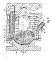
In der
Die Axialkolbenmaschine 1 weist ein Gehäuse auf, welches aus einem ersten, topfförmigen Gehäuseteil 3 und einem zweiten Gehäuseteil besteht, das als Flanschteil 4 ausgebildet ist. Eine in der
Auf ihrer dem Flanschteil 4 zugewandten Seite weist die Schwenkwiege 5 ein Schwenkwiegenlager 8 auf. Hierzu ist an der Schwenkwiege 5 zumindest ein erster Lagerbereich ausgebildet, welcher mit einer korrespondierenden Ausnehmung 9 des Flanschteils 4 ein Gleitlager ausbildet. Die Ausbildung des Schwenkwinkellagers der Schwenkwiege 5 wird nachfolgend unter Bezugnahme auf die
Die Schwenkwiege 5 ist durch Verdrehen der Schwenkwiege 5 in dem Schwenkwiegenlager um eine Schwenkachse S drehbar. Damit ändert sich die Neigung der Lauffläche 6 relativ zu der Rotationsachse der Zylindertrommel 2.The pivoting
Zur Einstellung der Neigung der Schwenkwiege 5 und damit des Hubs der Kolben in der Zylindertrommel 2 bei einer Drehung der Zylindertrommel 2 ist ein Stellsystem innerhalb des Gehäuses der Axialkolbenmaschine 1 vorgesehen. Das Stellsystem umfasst zumindest eine erste Stellvorrichtung 10. Die erste Stellvorrichtung 10 weist einen ersten Stellkolben 11 auf. Der erste Stellkolben 11 begrenzt mit seinem ersten Ende 12 eine Druckkammer 13. Die Druckkammer 13 ist in einem Boden des topfförmigen Gehäuseteils 3 ausgebildet. Zur Ausbildung der Druckkammer 13 wird eine Sackbohrung 14 in den Boden des topfförmigen Gehäuseteils 3 eingebracht, in die eine Buchse 15 eingesetzt wird. Die Buchse 15 wird vorzugsweise in die Sackbohrung 14 eingepresst. Die innere Wand der Buchse 15 dient dem ersten Ende 12 des Stellkolbens 11 als Gleitfläche und wirkt mit dem ersten Ende 12 des ersten Stellkolbens 11 dichtend zusammen. Das erste Ende 12 des Stellkolbens 11 ist nicht zylindrisch ausgebildet, sondern weist eine leicht ballige Form auf, um bei einer Schrägstellung des Stellkolbens 11 relativ zur Längsachse der Buchse 15 ein Verkanten in der Buchse 15 zu verhindern. Im balligen Bereich des ersten Endes 12 des Stellkolbens 11 könnte auch ein Dichtring angeordnet sein.To adjust the inclination of the pivoting
An einem von dem ersten Ende 12 abgewandten zweiten Ende 16 des Stellkolbens 11 ist ein Kugelkopf ausgebildet. Der Kugelkopf ist so mit einem Niederhaltesegment 17 verbunden, dass sowohl Zug- als auch Druckkräfte übertragen werden können. Das Niederhaltesegment 17 ist mittels Schrauben mit der Schwenkwiege 5 fest verbunden. Das Niederhaltesegment 17 ist auf die Lauffläche 6 in einem äußeren Bereich der Schwenkwiege 5 geschraubt. Das Niederhaltesegment 17 weist zudem eine Niederhaltefläche 19 auf, die die Rückzugplatte 7 übergreift und an der Rückzugplatte 7 anliegt und damit einen konstanten Abstand der Rückzugplatte 7 von der Lauffläche 6 der Schwenkwiege 5 sicherstellt.At one of the
Zur Fixierung des kugelkopfförmigen zweiten Endes 16 des Stellkolbens 11 ist in dem Niederhaltesegment 17 eine kugelförmige Ausnehmung 20 vorgesehen, welche das kugelkopfförmige zweite Ende 16 des Stellkolbens 11 umschließt. Die Verbindung des Stellkolbens 11 mit dem Niederhaltesegment 17 ist als arretierte Verbindung ausgeführt. D.h., dass das kugelkopfförmige zweite Ende 16 weiter als bis zum Äquator durch die kugelförmige Ausnehmung des Niederhaltesegments umschlossen ist.For fixing the ball-head-shaped
Im Inneren des Stellkolbens 11 in der ersten Stellvorrichtung 10 ist ein Schmiermittelkanal 21 ausgebildet. Der Schmiermittelkanal 21 erstreckt sich vom ersten Ende 12 des Stellkolbens 11 bis hin zum zweiten Ende 16. Damit verbindet der Schmiermittelkanal 21 die Druckkammer 13 mit dem kugelkopfförmigen zweiten Ende 16 des Stellkolbens 11. Ein in der Druckkammer 13 herrschender Druck sorgt damit für einen Austritt von Druckmittel an dem kugelkopfförmigen zweiten Ende 16 des Stellkolbens 11. Damit ist die gelenkige Verbindung zwischen dem Stellkolben 11 und dem Niederhaltesegment 17 geschmiert und hydrostatisch entlastet.Inside the
In der
Um eine Positionierung des Niederhaltesegments 17 relativ zu der Schwenkwiege 5 zu ermöglichen, ist ein Passstift 24 vorgesehen, der in eine Bohrung in die Schwenkwiege 5 und eine korrespondierende Bohrung in das Niederhaltesegment 17 eingesetzt ist. Ferner ist im Bereich eines von der Kugelgelenkverbindung zwischen dem Stellkolben 11 und dem Niederhaltesegment 17 abgewandten Endes des Niederhaltesegments 17 eine einstellbare erste Begrenzungsvorrichtung 25 in dem topfförmigen Gehäuseteil 3 vorgesehen. Die erste Begrenzungsvorrichtung 25 wirkt mit einer ersten Anschlagfläche 26 zusammen, welche an dem Niederhaltesegment 17 ausgebildet ist. Die erste Anschlagfläche 26 ist ballig ausgeführt, so dass unabhängig von der Einstellung der ersten Begrenzungsvorrichtung 25 die Krafteinleitung durch die Begrenzungsvorrichtung 25 senkrecht auf die erste Anschlagfläche 26 und damit durch den Mittelpunkt der Balligkeit erfolgt. Der Mittelpunkt dieser Balligkeit liegt von der Anschlagfläche aus betrachtet in Richtung der Schwenkwiege 5.In order to enable a positioning of the hold-
Die erste Begrenzungsvorrichtung 25 umfasst eine Einstellschraube 27, welche in ein dafür vorgesehenes Gewinde in eine Gehäusebohrung eingeschraubt ist. In Abhängigkeit von der Einschraubtiefe wird die maximale Auslenkung der Schwenkwiege 5 in einer ersten Bewegungsrichtung durch die erste Begrenzungsvorrichtung 25 festgelegt. Die Gehäusebohrung ist im Bereich des Mantels des topfförmigen Gehäuseteils 3 angeordnet. Sie schließt mit der Rotationsachse einen solchen Winkel ein, dass die Mittelachse der Einstellschraube 27 durch den Mittelpunkt der Balligkeit der Anschlagfläche 26 verläuft.The first limiting
Die erste Stellvorrichtung 10, die erste Begrenzungsvorrichtung 25 und das erste Niederhaltesegment 17 sind sämtlich einer ersten Bewegungsrichtung der Schwenkwiege 5 zugeordnet. Während die erste Stellvorrichtung 10 versucht die Schwenkwiege 5 in einer ersten Bewegungsrichtung zu verstellen, dient die erste Begrenzungsvorrichtung 25 als einstellbarer Anschlag und begrenzt damit die maximale Verstellung in dieser ersten Bewegungsrichtung. Um die Einstellschraube 27 in einer gewählten Position zu sichern, ist eine Kontermutter 28 vorgesehen. Die Kontermutter 28 dient gleichzeitig der Abdichtung des Gehäuseinnenraums gegenüber der Umgebung. Eine Sicherungskappe 29 verhindert unbefugtes Ändern der Einstellwerte.The
Um auch bei einer versehentlichen Verstellung der Einstellschraube 27 stets die Sicherheit der Axialkolbenmaschine 1 zu gewährleisten, ist ferner an dem gleichen Ende des Niederhaltesegments 17, an dem die Kugelverbindung zwischen dem zweiten Ende 16 des Stellkolbens 11 und dem ersten Niederhaltesegment 17 besteht, eine weitere Anschlagfläche 30 ausgebildet. Die weitere Anschlagfläche 30 ist auf der dem Flanschteil 4 zugewandten Seite ausgebildet und wirkt mit einem Gegenstück 51 des Flanschteils 4 zu einem Sicherheitsanschlag zusammen. Somit kann auch bei vollständig herausgeschraubter Einstellschraube 27 eine Verstellung lediglich bis zum Ansprechen des Sicherheitsanschlags erfolgen.In order always to ensure the safety of the
Bei einer Verstellung der Axialkolbenmaschine 1 in Richtung maximalen Hubvolumens wird bevorzugt der Sicherheitsanschlag zwischen dem Flanschteil 4 und der weiteren Anschlagfläche 30 des ersten Niederhaltesegments 17 ausgebildet.During an adjustment of the
Die erste Stellvorrichtung 10 und die erste Begrenzungsvorrichtung 25 sind, wie es sich unmittelbar aus der
Um die Axialkolbenmaschine 1 in Richtung maximalem Verdrängungsvolumens auch bei druckloser Druckkammer 13 vorzuspannen, ist an der ersten Stellvorrichtung 10 ein elastisches Element vorgesehen. Das elastische Element ist im dargestellten Ausführungsbeispiel als Feder 33 ausgeführt. Die Feder 33, die vorzugsweise eine Stahlspiralfeder ist, stützt sich einerseits an einem in der Nähe des zweiten Endes 16 ausgebildeten ersten Federlager 31 ab. Das Federlager 31 ist als radialer Absatz in dem Stellkolben 11 ausgebildet und weist einen sich in axialer Richtung geringfügig in Richtung des ersten Endes 12 des Stellkolbens 11 erstreckenden Führungsabschnitt zur Zentrierung der Feder 33 auf. Am gegenüberliegenden Ende der Feder 33 liegt die Feder 33 an einem zweiten Federlager 32 an. Das Federlager 32 weist ebenfalls einen Führungsabschnitt auf, der sich in axialer Richtung erstreckt. Das Federlager 32 ist in einer zentrierenden Ausnehmung 34 des Gehäuseteils 3 angeordnet und liegt dort an dem Boden des topfförmigen Gehäuseteils 3 an. Das Federlager 32 liegt dabei vorzugsweise gleichzeitig an dem Boden des topfförmigen Gehäuses 3 am Grund der zentrierenden Ausnehmung 34 und an der zum Innenraum des Gehäuses der Axialkolbenmaschine 1 orientierten Ende der Buchse 15 an.In order to bias the
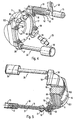
In der
In der Axialkolbenmaschine 1 ist ferner eine zweite Stellvorrichtung 35 vorgesehen, welche in der Darstellung der
Diese Anordnung ist in der
Es ist zu erkennen, dass die erste Stellvorrichtung 10 und die zweite Stellvorrichtung 35 auf bezüglich der Rotationsachse gegenüberliegenden Seiten liegen. Auch die zweite Stellvorrichtung 35 des Stellsystems weist einen Stellkolben auf, der mit seinem ersten Ende in einer zweiten Buchse 36 gelagert ist. Die zweite Buchse 36 ist ebenfalls in einer Sackbohrung in dem Boden des topfförmigen Gehäuseteils 3 eingesetzt. Damit wird eine zweite Druckkammer in der Buchse 36 ausgebildet, welche durch den Boden des topfförmigen Gehäuseteils 3, wie schon bei der ersten Stellvorrichtung 10, verschlossen ist. Der Druckraum bzw. die Druckkammer wird durch eine ebenfalls ballige Stellkolbenscheibe begrenzt. Über den gesamten Verstellweg des Stellsystems ist die jeweils ballige Stellkolbenscheibe sowohl des Stellkolbens 11 als auch des Stellkolbens der zweiten Stellvorrichtung 35 in der Buchse 15 bzw. der weiteren Buchse 36 geführt. An dem anderen Ende des Stellkolbens der zweiten Stellvorrichtung 35 ist ebenfalls eine Kugelgelenkverbindung ausgebildet. Das zweite Ende 37 des Stellkolbens der zweiten Stellvorrichtung 35 ist ebenfalls in eine sphärische Ausnehmung eines zweiten Niederhaltesegments 38 eingesetzt. Das zweite Niederhaltesegment 38 ist wie das erste Niederhaltesegment 17 mit der Schwenkwiege 5 mittels Schrauben 18 verbunden. Das erste und das zweite Niederhaltesegment 17 und 38 sind vorzugsweise identisch ausgeführt. Das erste Niederhaltesegment 17 erstreckt sich im Wesentlichen entlang der Ebene, in der die erste Stellvorrichtung 10 und die erste Begrenzungsvorrichtung 25 angeordnet sind. Dementsprechend erstreckt sich das zweite Niederhaltesegment 38 im Wesentlichen entlang einer weiteren Ebene, in der die zweite Stellvorrichtung 35 und eine zweite variable Begrenzungsvorrichtung 39 angeordnet sind. Die zweite variable Begrenzungsvorrichtung 39 entspricht in ihrem Aufbau der ersten variablen Begrenzungsvorrichtung 25, so dass auf eine erneute Beschreibung verzichtet wird.It can be seen that the
Betrachtet man einen Querschnitt durch die Axialkolbenmaschine 1, die typischerweise ein Gehäuse mit einem rechteckigen oder quadratischen Querschnitt aufweist, so sind die Stellvorrichtungen 10 und 35 auf einer ersten Diagonalen im Bereich der Innenecken des Gehäuses und die einstellbaren Begrenzungsvorrichtungen 25 und 39 auf einer zweiten Diagonalen im Bereich der Innenecken des Gehäuses angeordnet. Unterteilt man in einem solchen Schnitt die Axialkolbenmaschinen in 4 Quadranten, so ist die erste Stellvorrichtung 10 in dem ersten Quadranten, die erste Begrenzungsvorrichtung 25 in dem vierten Quadranten, die zweite Stellvorrichtung 35 in dem dritten Quadranten und die zweite einstellbare Begrenzungsvorrichtung 39 in dem zweiten Quadranten angeordnet.Considering a cross section through the
An dem zweiten Niederhaltesegment 38 ist ebenfalls eine Anschlagfläche 40 ausgebildet, die ballig ausgeführt ist. Die ballige Ausbildung der Anschlagfläche 40 hat, wie schon bei dem ersten Niederhaltesegment 17 zur Folge, dass unabhängig von der gewählten Einstellung der variablen Begrenzungsvorrichtung 39 die Krafteinleitung immer senkrecht auf der Anschlagfläche 40 steht. Zur Ausbildung eines Sicherheitsanschlags ist auch an dem zweiten Niederhaltesegment 38 eine weitere Anschlagfläche 41 ausgebildet. Die weitere Anschlagfläche 41 ist an demselben Ende des zweiten Niederhaltesegments 38 ausgebildet, wie die Kugelgelenkverbindung mit dem Stellkolben der zweiten Stellvorrichtung 35.At the second hold-
In der
In der
Es ist in der
Ferner ist es erkennbar, dass die Schwenkwiege 5 mittig von einer Bohrung 45 durchsetzt ist. Diese Bohrung 45 bildet einen Durchlass für die Triebwelle der Axialkolbenmaschine 1.Furthermore, it can be seen that the pivoting
In der
Die
Die Erfindung ist nicht auf die dargestellten Ausführungsbeispiele beschränkt. Insbesondere ist es möglich, einzelne Merkmale der dargestellten Ausführungsbeispiele in vorteilhafter Weise miteinander zu kombinieren.The invention is not limited to the illustrated embodiments. In particular, it is possible to combine individual features of the illustrated embodiments in an advantageous manner.
Claims (16)
- Axial piston machine with a pivoting cradle (5), of which the inclination with respect to an axis of rotation of a cylindrical drum (2) can be varied, and with an actuating system acting upon the pivoting cradle (5) and having a first actuating device (10) for adjusting the inclination of the pivoting cradle (5) in a first direction of movement, and having a second actuating device (35) for adjusting the inclination of the pivoting cradle (5) in an opposite second direction of movement, the first and the second actuating devices (10, 35) acting upon the pivoting cradle (5) on sides lying opposite one another with respect to the axis of rotation, and with a device for limiting the movement of the pivoting cradle (5), characterized in that the device for limiting the movement of the pivoting cradle has a first settable limiting device (25) and a second settable limiting device (39) which in each case act upon the pivoting cradle (5) and are arranged on opposite sides of the pivoting cradle (5) with respect to the axis of rotation, the regions in which the first and the second actuating device (10, 35) are arranged and the regions in which the first and the second limiting device (25, 39) are arranged differing from one another, the first and the second settable limiting device (25, 39) comprising a set screw (27, 39) which is screwed into a housing bore into a thread provided for this purpose, and the first and/or the second actuating device (10, 35) comprising an elastic element (33) which loads the pivoting cradle (5) with a force acting in the first direction of movement or with a force acting in the second direction of movement.
- Axial piston machine according to Claim 1, characterized in that a pivot axis (S) of the pivoting cradle (5) and the axis of rotation stand perpendicularly to one another, and the first actuating device (10) and/or the second actuating device (35) are/is formed in each case in a plane lying parallel to the axis of rotation and standing perpendicularly to the pivot axis (S).
- Axial piston machine according to Claim 2, characterized in that the first actuating device (10) and the first limiting device (25) limiting the movement of the pivoting cradle (5) in the first direction are arranged in a plane, the surface normal of which runs parallel to a pivot axis (S) of the pivoting cradle (5), and/or in that the second actuating device (35) and the second limiting device (39) limiting the movement of the pivoting cradle (5) in the second direction are arranged in a further plane, the surface normal of which runs parallel to a pivot axis (S) of the pivoting cradle (5).
- Axial piston machine according to one of Claims 1 to 3, characterized in that the first actuating device (10) and/or the second actuating device (35) have/has in each case an actuating piston (11).
- Axial piston machine according to Claim 4, characterized in that there is provided for each actuating piston (11) in the housing (3, 4), on the side lying opposite the pivoting cradle (5), a blind bore (14) in which that end of the actuating piston (11) which in each case faces away from the pivoting cradle (5) is guided.
- Axial piston machine according to Claim 5, characterized in that the actuating pistons (11) have a crowned actuating-piston disc at their end (12) arranged in the blind bore (14).
- Axial piston machine according to one of Claims 3 to 6, characterized in that in each case a second end (16, 37), transmitting an actuating force to the pivoting cradle (5), of an actuating piston (11) is connected to the pivoting cradle (5) in each case via a holding-down segment (17, 38).
- Axial piston machine according to Claims 3 to 7, characterized in that a ball-headed connection which is relieved hydrostatically is designed for connecting the actuating piston (11) to the pivoting cradle (5) or to the holding-down segment (17, 38).
- Axial piston machine according to Claim 7 or 8, characterized in that each holding-down segment (17, 38) has additionally a stop face (26, 40) for limiting the movement of the pivoting cradle (5) in the direction of movement predetermined by the assigned actuating device (10, 35) and which cooperates with the corresponding first or second limiting device (25, 39).
- Axial piston machine according to Claim 9, characterized in that a further stop face (30, 41) is formed additionally on each holding-down segment (17, 38) and cooperates in each case with a housing-side counterpiece (51) to form a safety stop.
- Axial piston machine according to Claim 10, characterized in that the counterpiece or counterpieces (51) is or are formed on a pot-shaped housing parts (3) or on a flange part (4).
- Axial piston machine according to one of Claims 1 to 9, characterized in that the first actuating device (10) has a first actuating piston (11) and/or in that the second actuating device (35) has a second actuating piston, there being formed in at least one of the actuating pistons (11) a pressure-medium duct which connects the assigned blind bore (14) to that end (16) of the actuating piston (11) which faces the pivoting cradle (5).
- Axial piston machine according to Claim 8, characterized in that there are formed in the pivoting cradle (5) and/or in a holding-down segment (17, 38) further ducts, via which pressure medium can be fed from the blind bore (14) to at least one bearing face (8.1, 8.2) of the pivoting cradle (5).
- Axial piston machine according to one of Claims 1 to 11, characterized in that the pivoting cradle (5) can be pivoted in two opposite directions, starting from a neutral position in which a surface normal of a running surface (6) of the pivoting cradle (5) runs parallel to the axis of rotation.
- Axial piston machine according to one of the preceding claims, characterized in that the elastic element (33) is a helical spring (33) which surrounds an adjusting piston (11) of the first or the second actuating device (10, 35) and which is supported on the housing side on a spring plate (32).
- Axial piston machine according to Claim 15, characterized in that the spring plate (32) bears against the bottom of a pot-shaped housing part (3) or bears against a bearing ring (46) at a distance from the bottom of the pot-shaped housing part (3).
Applications Claiming Priority (2)
| Application Number | Priority Date | Filing Date | Title |
|---|---|---|---|
| DE102007022567A DE102007022567A1 (en) | 2007-05-14 | 2007-05-14 | axial piston |
| PCT/EP2008/003868 WO2008138604A2 (en) | 2007-05-14 | 2008-05-14 | Axial piston machine |
Publications (2)
| Publication Number | Publication Date |
|---|---|
| EP2145105A2 EP2145105A2 (en) | 2010-01-20 |
| EP2145105B1 true EP2145105B1 (en) | 2012-11-21 |
Family
ID=39868687
Family Applications (1)
| Application Number | Title | Priority Date | Filing Date |
|---|---|---|---|
| EP08749455A Active EP2145105B1 (en) | 2007-05-14 | 2008-05-14 | Axial piston machine |
Country Status (5)
| Country | Link |
|---|---|
| US (1) | US8261654B2 (en) |
| EP (1) | EP2145105B1 (en) |
| JP (1) | JP5144750B2 (en) |
| DE (1) | DE102007022567A1 (en) |
| WO (1) | WO2008138604A2 (en) |
Families Citing this family (9)
| Publication number | Priority date | Publication date | Assignee | Title |
|---|---|---|---|---|
| DE102006062065A1 (en) * | 2006-12-29 | 2008-07-03 | Robert Bosch Gmbh | Hydrostatic axial piston machine e.g. swash plate machine, has periphery wall with radial elevation formed in longitudinal direction of housing and formed by two periphery wall sections that limit radially extended interior section |
| US8647075B2 (en) | 2009-03-18 | 2014-02-11 | Eaton Corporation | Control valve for a variable displacement pump |
| CN103026063B (en) * | 2010-07-08 | 2016-03-30 | 罗伯特·博世有限公司 | Hydraulic dual axial piston |
| DE102011105544A1 (en) * | 2010-07-08 | 2012-01-12 | Robert Bosch Gmbh | Hydraulic axial piston machine |
| DE102011116962A1 (en) | 2010-10-30 | 2012-05-03 | Robert Bosch Gmbh | Axial piston machine of swash plate construction, has sight glass that is inserted into receptacle in housing comprising pivoting cradle on which cylindrical drums are supported |
| DE102011113533A1 (en) * | 2011-09-15 | 2013-03-21 | Robert Bosch Gmbh | Hydrostatic axial piston machine user for swash plate construction, has cylinder piston unit whose axial section is encompassed with spring |
| GB2502824A (en) * | 2012-06-08 | 2013-12-11 | Water Hydraulics Company Ltd | Axial piston variable stroke hydraulic machine |
| US9664184B2 (en) * | 2013-05-22 | 2017-05-30 | Hydac Drive Center Gmbh | Axial piston pump having a swash-plate type construction |
| WO2022156967A1 (en) * | 2021-01-22 | 2022-07-28 | Danfoss Power Solutions Gmbh & Co. Ohg | Axial piston machine with swivel element actuated by a servo unit for adjusting the displacement volume |
Family Cites Families (13)
| Publication number | Priority date | Publication date | Assignee | Title |
|---|---|---|---|---|
| US1573525A (en) * | 1925-09-29 | 1926-02-16 | Tavannes Watch Co Sa | Multicylinder pump |
| US1749682A (en) * | 1926-09-03 | 1930-03-04 | Weldy Arthur Sheldon | Pump |
| US2455062A (en) | 1943-07-12 | 1948-11-30 | Lucas Ltd Joseph | Variable stroke pump |
| US3274948A (en) * | 1964-07-02 | 1966-09-27 | Sundstrand Corp | Pump or motor wobbler mounting |
| US3373696A (en) * | 1965-05-12 | 1968-03-19 | Gen Electric | Fluid transmission devices |
| GB1200180A (en) * | 1966-12-14 | 1970-07-29 | Dowty Technical Dev Ltd | Swash plate pump |
| FR1590650A (en) * | 1968-07-08 | 1970-04-20 | ||
| US3830594A (en) * | 1971-06-28 | 1974-08-20 | Caterpillar Tractor Co | Variable displacement pump having pressure compensator control method |
| GB1548095A (en) * | 1976-05-10 | 1979-07-04 | Bryce J M | Apparatus and method for attaching a wire to a supporting post |
| US4168653A (en) * | 1976-12-20 | 1979-09-25 | Caterpillar Tractor Co. | Two position variable displacement motor |
| JPH0526151A (en) * | 1991-07-16 | 1993-02-02 | Toyota Autom Loom Works Ltd | Hydraulic drive unit |
| US6705203B2 (en) * | 2001-11-28 | 2004-03-16 | Sauer-Danfoss Inc. | Extended male slipper servo pad arrangement for positioning swashplate and method assembling same |
| DE102006062065A1 (en) * | 2006-12-29 | 2008-07-03 | Robert Bosch Gmbh | Hydrostatic axial piston machine e.g. swash plate machine, has periphery wall with radial elevation formed in longitudinal direction of housing and formed by two periphery wall sections that limit radially extended interior section |
-
2007
- 2007-05-14 DE DE102007022567A patent/DE102007022567A1/en not_active Withdrawn
-
2008
- 2008-05-14 US US12/599,383 patent/US8261654B2/en active Active
- 2008-05-14 EP EP08749455A patent/EP2145105B1/en active Active
- 2008-05-14 JP JP2010506866A patent/JP5144750B2/en active Active
- 2008-05-14 WO PCT/EP2008/003868 patent/WO2008138604A2/en active Application Filing
Also Published As
| Publication number | Publication date |
|---|---|
| JP2010526246A (en) | 2010-07-29 |
| WO2008138604A2 (en) | 2008-11-20 |
| WO2008138604A3 (en) | 2009-09-17 |
| DE102007022567A1 (en) | 2008-11-20 |
| EP2145105A2 (en) | 2010-01-20 |
| JP5144750B2 (en) | 2013-02-13 |
| US20100307330A1 (en) | 2010-12-09 |
| US8261654B2 (en) | 2012-09-11 |
Similar Documents
| Publication | Publication Date | Title |
|---|---|---|
| EP2145105B1 (en) | Axial piston machine | |
| EP2145107B1 (en) | Retaining segment | |
| DE102006057364B4 (en) | Water hydraulic machine | |
| EP2145106B1 (en) | Axial piston machine having a return device | |
| WO2009024336A1 (en) | Axial piston machine in a swash-plate construction with an actuating device | |
| DE102007048316B4 (en) | Hydraulic axial piston machine | |
| EP1588052B1 (en) | Axial piston machine comprising a crosshead which can be fixed to the swash plate | |
| WO2012034619A1 (en) | Axial piston machine | |
| EP1636459B1 (en) | Longitudinally adjustable reversible axial piston machine | |
| DE3519783A1 (en) | AXIAL PISTON MACHINE | |
| DE10037482C1 (en) | Hydrostatic variable displacement pump with springs located outside the servo cylinder pressure chamber | |
| DE19755386C2 (en) | Hydrostatic machine with a rotatably mounted cylinder drum and an adjustable swivel disc | |
| EP1427914B1 (en) | Hydrostatic machine with compensated sleeves | |
| DE19855899B4 (en) | axial piston | |
| DE3728448C2 (en) | ||
| DE102020211284A1 (en) | Hydrostatic axial piston machine in swash plate design | |
| EP1700034B1 (en) | Axial piston machine for independent delivery into several hydraulic circuits | |
| EP1156212B1 (en) | Axial piston machine with cylinder sleeves for the reciprocating pistons | |
| DE10347085B3 (en) | Hydrostatic piston machine with two hydraulic circuits | |
| EP2390497B1 (en) | Hydrostatic machine | |
| DE102018205884A1 (en) | Axial piston machine with pressure relief in the Durchtriebsraum | |
| DE102021212098A1 (en) | Sliding shoe for an axial piston machine and axial piston machine therewith | |
| DE102018205446A1 (en) | Hydrostatic axial piston machine | |
| DE10157248A1 (en) | Hydrostatic machine with compensated liners | |
| DE102005025512B4 (en) | Swash plate axial piston machine with swing-wing adjustment of the cradle |
Legal Events
| Date | Code | Title | Description |
|---|---|---|---|
| PUAI | Public reference made under article 153(3) epc to a published international application that has entered the european phase |
Free format text: ORIGINAL CODE: 0009012 |
|
| 17P | Request for examination filed |
Effective date: 20090928 |
|
| AK | Designated contracting states |
Kind code of ref document: A2 Designated state(s): AT BE BG CH CY CZ DE DK EE ES FI FR GB GR HR HU IE IS IT LI LT LU LV MC MT NL NO PL PT RO SE SI SK TR |
|
| AX | Request for extension of the european patent |
Extension state: AL BA MK RS |
|
| 17Q | First examination report despatched |
Effective date: 20100413 |
|
| DAX | Request for extension of the european patent (deleted) | ||
| GRAP | Despatch of communication of intention to grant a patent |
Free format text: ORIGINAL CODE: EPIDOSNIGR1 |
|
| GRAS | Grant fee paid |
Free format text: ORIGINAL CODE: EPIDOSNIGR3 |
|
| GRAA | (expected) grant |
Free format text: ORIGINAL CODE: 0009210 |
|
| AK | Designated contracting states |
Kind code of ref document: B1 Designated state(s): AT BE BG CH CY CZ DE DK EE ES FI FR GB GR HR HU IE IS IT LI LT LU LV MC MT NL NO PL PT RO SE SI SK TR |
|
| REG | Reference to a national code |
Ref country code: GB Ref legal event code: FG4D Free format text: NOT ENGLISH |
|
| REG | Reference to a national code |
Ref country code: CH Ref legal event code: EP |
|
| REG | Reference to a national code |
Ref country code: AT Ref legal event code: REF Ref document number: 585222 Country of ref document: AT Kind code of ref document: T Effective date: 20121215 |
|
| REG | Reference to a national code |
Ref country code: IE Ref legal event code: FG4D Free format text: LANGUAGE OF EP DOCUMENT: GERMAN |
|
| REG | Reference to a national code |
Ref country code: DE Ref legal event code: R096 Ref document number: 502008008700 Country of ref document: DE Effective date: 20130117 |
|
| REG | Reference to a national code |
Ref country code: SE Ref legal event code: TRGR |
|
| REG | Reference to a national code |
Ref country code: NL Ref legal event code: VDEP Effective date: 20121121 |
|
| REG | Reference to a national code |
Ref country code: LT Ref legal event code: MG4D |
|
| PG25 | Lapsed in a contracting state [announced via postgrant information from national office to epo] |
Ref country code: ES Free format text: LAPSE BECAUSE OF FAILURE TO SUBMIT A TRANSLATION OF THE DESCRIPTION OR TO PAY THE FEE WITHIN THE PRESCRIBED TIME-LIMIT Effective date: 20130304 Ref country code: NO Free format text: LAPSE BECAUSE OF FAILURE TO SUBMIT A TRANSLATION OF THE DESCRIPTION OR TO PAY THE FEE WITHIN THE PRESCRIBED TIME-LIMIT Effective date: 20130221 Ref country code: FI Free format text: LAPSE BECAUSE OF FAILURE TO SUBMIT A TRANSLATION OF THE DESCRIPTION OR TO PAY THE FEE WITHIN THE PRESCRIBED TIME-LIMIT Effective date: 20121121 Ref country code: LT Free format text: LAPSE BECAUSE OF FAILURE TO SUBMIT A TRANSLATION OF THE DESCRIPTION OR TO PAY THE FEE WITHIN THE PRESCRIBED TIME-LIMIT Effective date: 20121121 |
|
| PG25 | Lapsed in a contracting state [announced via postgrant information from national office to epo] |
Ref country code: SI Free format text: LAPSE BECAUSE OF FAILURE TO SUBMIT A TRANSLATION OF THE DESCRIPTION OR TO PAY THE FEE WITHIN THE PRESCRIBED TIME-LIMIT Effective date: 20121121 Ref country code: PT Free format text: LAPSE BECAUSE OF FAILURE TO SUBMIT A TRANSLATION OF THE DESCRIPTION OR TO PAY THE FEE WITHIN THE PRESCRIBED TIME-LIMIT Effective date: 20130321 Ref country code: LV Free format text: LAPSE BECAUSE OF FAILURE TO SUBMIT A TRANSLATION OF THE DESCRIPTION OR TO PAY THE FEE WITHIN THE PRESCRIBED TIME-LIMIT Effective date: 20121121 Ref country code: PL Free format text: LAPSE BECAUSE OF FAILURE TO SUBMIT A TRANSLATION OF THE DESCRIPTION OR TO PAY THE FEE WITHIN THE PRESCRIBED TIME-LIMIT Effective date: 20121121 Ref country code: GR Free format text: LAPSE BECAUSE OF FAILURE TO SUBMIT A TRANSLATION OF THE DESCRIPTION OR TO PAY THE FEE WITHIN THE PRESCRIBED TIME-LIMIT Effective date: 20130222 |
|
| PG25 | Lapsed in a contracting state [announced via postgrant information from national office to epo] |
Ref country code: EE Free format text: LAPSE BECAUSE OF FAILURE TO SUBMIT A TRANSLATION OF THE DESCRIPTION OR TO PAY THE FEE WITHIN THE PRESCRIBED TIME-LIMIT Effective date: 20121121 Ref country code: DK Free format text: LAPSE BECAUSE OF FAILURE TO SUBMIT A TRANSLATION OF THE DESCRIPTION OR TO PAY THE FEE WITHIN THE PRESCRIBED TIME-LIMIT Effective date: 20121121 Ref country code: BG Free format text: LAPSE BECAUSE OF FAILURE TO SUBMIT A TRANSLATION OF THE DESCRIPTION OR TO PAY THE FEE WITHIN THE PRESCRIBED TIME-LIMIT Effective date: 20130221 Ref country code: CZ Free format text: LAPSE BECAUSE OF FAILURE TO SUBMIT A TRANSLATION OF THE DESCRIPTION OR TO PAY THE FEE WITHIN THE PRESCRIBED TIME-LIMIT Effective date: 20121121 Ref country code: SK Free format text: LAPSE BECAUSE OF FAILURE TO SUBMIT A TRANSLATION OF THE DESCRIPTION OR TO PAY THE FEE WITHIN THE PRESCRIBED TIME-LIMIT Effective date: 20121121 |
|
| PGFP | Annual fee paid to national office [announced via postgrant information from national office to epo] |
Ref country code: SE Payment date: 20130521 Year of fee payment: 6 Ref country code: GB Payment date: 20130522 Year of fee payment: 6 |
|
| PG25 | Lapsed in a contracting state [announced via postgrant information from national office to epo] |
Ref country code: RO Free format text: LAPSE BECAUSE OF FAILURE TO SUBMIT A TRANSLATION OF THE DESCRIPTION OR TO PAY THE FEE WITHIN THE PRESCRIBED TIME-LIMIT Effective date: 20121121 Ref country code: NL Free format text: LAPSE BECAUSE OF FAILURE TO SUBMIT A TRANSLATION OF THE DESCRIPTION OR TO PAY THE FEE WITHIN THE PRESCRIBED TIME-LIMIT Effective date: 20121121 |
|
| PGFP | Annual fee paid to national office [announced via postgrant information from national office to epo] |
Ref country code: FR Payment date: 20130604 Year of fee payment: 6 Ref country code: IT Payment date: 20130525 Year of fee payment: 6 |
|
| PLBE | No opposition filed within time limit |
Free format text: ORIGINAL CODE: 0009261 |
|
| STAA | Information on the status of an ep patent application or granted ep patent |
Free format text: STATUS: NO OPPOSITION FILED WITHIN TIME LIMIT |
|
| 26N | No opposition filed |
Effective date: 20130822 |
|
| PG25 | Lapsed in a contracting state [announced via postgrant information from national office to epo] |
Ref country code: HR Free format text: LAPSE BECAUSE OF FAILURE TO SUBMIT A TRANSLATION OF THE DESCRIPTION OR TO PAY THE FEE WITHIN THE PRESCRIBED TIME-LIMIT Effective date: 20121121 |
|
| BERE | Be: lapsed |
Owner name: ROBERT BOSCH G.M.B.H. Effective date: 20130531 |
|
| REG | Reference to a national code |
Ref country code: DE Ref legal event code: R097 Ref document number: 502008008700 Country of ref document: DE Effective date: 20130822 |
|
| PG25 | Lapsed in a contracting state [announced via postgrant information from national office to epo] |
Ref country code: MC Free format text: LAPSE BECAUSE OF FAILURE TO SUBMIT A TRANSLATION OF THE DESCRIPTION OR TO PAY THE FEE WITHIN THE PRESCRIBED TIME-LIMIT Effective date: 20121121 |
|
| REG | Reference to a national code |
Ref country code: CH Ref legal event code: PL |
|
| PG25 | Lapsed in a contracting state [announced via postgrant information from national office to epo] |
Ref country code: LI Free format text: LAPSE BECAUSE OF NON-PAYMENT OF DUE FEES Effective date: 20130531 Ref country code: CH Free format text: LAPSE BECAUSE OF NON-PAYMENT OF DUE FEES Effective date: 20130531 |
|
| REG | Reference to a national code |
Ref country code: IE Ref legal event code: MM4A |
|
| PG25 | Lapsed in a contracting state [announced via postgrant information from national office to epo] |
Ref country code: BE Free format text: LAPSE BECAUSE OF NON-PAYMENT OF DUE FEES Effective date: 20130531 |
|
| PG25 | Lapsed in a contracting state [announced via postgrant information from national office to epo] |
Ref country code: IE Free format text: LAPSE BECAUSE OF NON-PAYMENT OF DUE FEES Effective date: 20130514 |
|
| REG | Reference to a national code |
Ref country code: AT Ref legal event code: MM01 Ref document number: 585222 Country of ref document: AT Kind code of ref document: T Effective date: 20130514 |
|
| PG25 | Lapsed in a contracting state [announced via postgrant information from national office to epo] |
Ref country code: AT Free format text: LAPSE BECAUSE OF NON-PAYMENT OF DUE FEES Effective date: 20130514 |
|
| GBPC | Gb: european patent ceased through non-payment of renewal fee |
Effective date: 20140514 |
|
| PG25 | Lapsed in a contracting state [announced via postgrant information from national office to epo] |
Ref country code: SE Free format text: LAPSE BECAUSE OF NON-PAYMENT OF DUE FEES Effective date: 20140515 |
|
| REG | Reference to a national code |
Ref country code: SE Ref legal event code: EUG |
|
| PG25 | Lapsed in a contracting state [announced via postgrant information from national office to epo] |
Ref country code: MT Free format text: LAPSE BECAUSE OF FAILURE TO SUBMIT A TRANSLATION OF THE DESCRIPTION OR TO PAY THE FEE WITHIN THE PRESCRIBED TIME-LIMIT Effective date: 20121121 |
|
| REG | Reference to a national code |
Ref country code: FR Ref legal event code: ST Effective date: 20150130 |
|
| PG25 | Lapsed in a contracting state [announced via postgrant information from national office to epo] |
Ref country code: IT Free format text: LAPSE BECAUSE OF NON-PAYMENT OF DUE FEES Effective date: 20140514 |
|
| PG25 | Lapsed in a contracting state [announced via postgrant information from national office to epo] |
Ref country code: FR Free format text: LAPSE BECAUSE OF NON-PAYMENT OF DUE FEES Effective date: 20140602 Ref country code: GB Free format text: LAPSE BECAUSE OF NON-PAYMENT OF DUE FEES Effective date: 20140514 |
|
| PG25 | Lapsed in a contracting state [announced via postgrant information from national office to epo] |
Ref country code: CY Free format text: LAPSE BECAUSE OF FAILURE TO SUBMIT A TRANSLATION OF THE DESCRIPTION OR TO PAY THE FEE WITHIN THE PRESCRIBED TIME-LIMIT Effective date: 20121121 Ref country code: TR Free format text: LAPSE BECAUSE OF FAILURE TO SUBMIT A TRANSLATION OF THE DESCRIPTION OR TO PAY THE FEE WITHIN THE PRESCRIBED TIME-LIMIT Effective date: 20121121 |
|
| PG25 | Lapsed in a contracting state [announced via postgrant information from national office to epo] |
Ref country code: HU Free format text: LAPSE BECAUSE OF FAILURE TO SUBMIT A TRANSLATION OF THE DESCRIPTION OR TO PAY THE FEE WITHIN THE PRESCRIBED TIME-LIMIT; INVALID AB INITIO Effective date: 20080514 Ref country code: LU Free format text: LAPSE BECAUSE OF NON-PAYMENT OF DUE FEES Effective date: 20130514 |
|
| PG25 | Lapsed in a contracting state [announced via postgrant information from national office to epo] |
Ref country code: IS Free format text: LAPSE BECAUSE OF FAILURE TO SUBMIT A TRANSLATION OF THE DESCRIPTION OR TO PAY THE FEE WITHIN THE PRESCRIBED TIME-LIMIT Effective date: 20121121 |
|
| P01 | Opt-out of the competence of the unified patent court (upc) registered |
Effective date: 20230509 |
|
| PGFP | Annual fee paid to national office [announced via postgrant information from national office to epo] |
Ref country code: DE Payment date: 20230726 Year of fee payment: 16 |