EP2144046A2 - Temperaturempfindliche und Temperatur bestimmende Anordnung - Google Patents
Temperaturempfindliche und Temperatur bestimmende Anordnung Download PDFInfo
- Publication number
- EP2144046A2 EP2144046A2 EP09161753A EP09161753A EP2144046A2 EP 2144046 A2 EP2144046 A2 EP 2144046A2 EP 09161753 A EP09161753 A EP 09161753A EP 09161753 A EP09161753 A EP 09161753A EP 2144046 A2 EP2144046 A2 EP 2144046A2
- Authority
- EP
- European Patent Office
- Prior art keywords
- base plate
- sensor unit
- arrangement according
- surface area
- foil
- Prior art date
- Legal status (The legal status is an assumption and is not a legal conclusion. Google has not performed a legal analysis and makes no representation as to the accuracy of the status listed.)
- Withdrawn
Links
Images

Classifications
-
- G—PHYSICS
- G01—MEASURING; TESTING
- G01K—MEASURING TEMPERATURE; MEASURING QUANTITY OF HEAT; THERMALLY-SENSITIVE ELEMENTS NOT OTHERWISE PROVIDED FOR
- G01K1/00—Details of thermometers not specially adapted for particular types of thermometer
- G01K1/16—Special arrangements for conducting heat from the object to the sensitive element
-
- G—PHYSICS
- G01—MEASURING; TESTING
- G01K—MEASURING TEMPERATURE; MEASURING QUANTITY OF HEAT; THERMALLY-SENSITIVE ELEMENTS NOT OTHERWISE PROVIDED FOR
- G01K7/00—Measuring temperature based on the use of electric or magnetic elements directly sensitive to heat ; Power supply therefor, e.g. using thermoelectric elements
- G01K7/01—Measuring temperature based on the use of electric or magnetic elements directly sensitive to heat ; Power supply therefor, e.g. using thermoelectric elements using semiconducting elements having PN junctions
-
- G—PHYSICS
- G01—MEASURING; TESTING
- G01K—MEASURING TEMPERATURE; MEASURING QUANTITY OF HEAT; THERMALLY-SENSITIVE ELEMENTS NOT OTHERWISE PROVIDED FOR
- G01K7/00—Measuring temperature based on the use of electric or magnetic elements directly sensitive to heat ; Power supply therefor, e.g. using thermoelectric elements
- G01K7/42—Circuits effecting compensation of thermal inertia; Circuits for predicting the stationary value of a temperature
- G01K7/425—Thermal management of integrated systems
-
- H—ELECTRICITY
- H02—GENERATION; CONVERSION OR DISTRIBUTION OF ELECTRIC POWER
- H02H—EMERGENCY PROTECTIVE CIRCUIT ARRANGEMENTS
- H02H5/00—Emergency protective circuit arrangements for automatic disconnection directly responsive to an undesired change from normal non-electric working conditions with or without subsequent reconnection
- H02H5/04—Emergency protective circuit arrangements for automatic disconnection directly responsive to an undesired change from normal non-electric working conditions with or without subsequent reconnection responsive to abnormal temperature
- H02H5/044—Emergency protective circuit arrangements for automatic disconnection directly responsive to an undesired change from normal non-electric working conditions with or without subsequent reconnection responsive to abnormal temperature using a semiconductor device to sense the temperature
Definitions
- the present invention relates generally to a temperature sensitive arrangement and more specifically to a temperature detecting and/or determining arrangement, in which it is to be possible to disconnect a current fed electric and/or electronic circuit as soon as a detected and determined temperature exceeds and/or tends to exceed a predetermined value.
- the present invention is related to a temperature sensitive arrangement such that it will be able to provide rapid disconnection of a feed current to an electronic circuit or an electric circuit arrangement in order to protect sensitive electrical, electronic circuits, chips and/or transistors from overloads as a result of overheating.
- the intended application of the invention is consequently in the event of rapidly occurring, increasing current feeds and/or current variations, which are normally associated with short circuit currents.
- the present invention is intended to be based on a temperature sensitive arrangement such that, connected to a current fed circuit arrangement, with a voltage source, a connecting and/or disconnecting unit for the feed current and one or more voltage and current feeding electrical circuits, which must at least comprise:
- the present invention is based on a design such that the sensor body must be fixed to one (the inner) of the two surface lengths of the base plate such that effective heat transfer will take place between the sensor body and the base plate, whereas the oppositely placed and other (outer) surface length of the base plate is related to the cooling body such that effective heat transfer will take place between the base plate and the cooling body.
- the intended application of the present invention is primarily at the fuse unit and the intended application is at, and connectable to, an electrically current fed circuit arrangement.
- Such current fed circuit arrangements display: a voltage source, a fuse unit, a connecting and disconnecting unit for a connected current feed and one or more voltage and current feeding electrical circuits.
- Fuse units are known in a number of different embodiments.
- a first category of fuse units utilizes a thin wire, inserted in series with the feed cable and feed current of the electric circuit, and in the event of an excessively high current, and heat generation related thereto, the wire melts through and breaks the current circuit
- a second category of fuse units is structured to sense current values, instantaneous and/or formed by mean value formation, and in the event of an excessively high current value to cause a mechanism, related to the connecting or disconnecting unit, to be affected to mechanically break the feed current.
- the fuse unit of relevant type has been designed to offer "slow blow/slow acting" or "fast blow/fast acting” functions, whereby an embodiment offering the slow acting function is intended to be able to allow rapidly occurring overcurrents without blowing, while an embodiment offering the fast acting function is not intended to be able to allow such overcurrents and therefore blows considerably faster.
- the intended application of the present invention is in such electronic circuit arrangements and fuse units in which sensed current values must be evaluated by way of electronic circuits and in which the current values will primarily be evaluated by way of heat generation related to the current value.
- an electronic circuit in the form of an electronic switch unit with a temperature sensitive and temperature determining arrangement, connected in a current fed circuit arrangement, with a voltage source, a connecting and/or disconnecting unit for the current feed, and one or more voltage and current feeding electrical circuits, in which the utilized arrangement comprises: a sensor unit adapted to sensing of the temperature; a first electronic circuit arrangement, connected to the sensor unit, to determine an instantaneously occurring temperature; a sensor body enabling an electric current to flow through it and heatable by instantaneous current values; among other things, a part (the greater part) of the base plate absorbing the heat energy thus generated within the sensor body; and one or more cooling bodies to which a part of the heat energy absorbed by the base plate is adapted to be transferred.
- the sensor body can be fixed to the one surface length of the base plate so that effective heat conduction will occur between the sensor body and the base plate, primarily from the sensor body, while the oppositely placed and other surface length of the base plate must be so related to the cooling body that effective heat transfer will be able to occur between the base plate and the cooling body.
- Electronic switch units of relevant type are previously known as such and a unit which will be possible to use to advantage within the present invention is a circuit unit which is based on one or more transistors allowing current to flow through, exemplified by MOSFET transistors.
- Such switch units are specially adapted to be able to conduct current within chosen limits and with a moderate heat development.
- such units are adapted to "switch" the current (a function with fast on and off switches and with current-disconnecting intervening times) in order thus to limit the output power, and primarily the current feed.
- This adjustment may take place within certain chosen limits and in which the temperature generated by the transistors is within the chosen value limits.
- Units of the relevant type are normally combined with large cooling bodies with high thermal capacity, which contributes to undesirably slow temperature sensing and an imminent risk that the transistor will bum or melt, resulting in a complicated and costly replacement.
- control circuit related circuit arrangement comprises/contain a first circuit unit or module, to determine and follow the instantaneous values of the temperature and/or the current.
- control circuit related circuit arrangement comprises/contain a second circuit unit or module, to determine and follow values for the time derivative of a temperature change.
- a temperature sensitive and temperature sensing arrangement must include/comprise: a temperature sensing sensor unit, a first circuit arrangement, a sensor body heatable by an electric current, a base plate transferring heat energy generated within and from the sensor body, and/or one or more cooling bodies transferring heat energy from the base plate, and in which the sensor body must be attached to the base plate such that effective heat transfer occurs between the sensor body and the base plate, in accordance with the preconditions which are detailed in the introduction of claim 1,
- the present invention more particularly specifies that a second surface length allocated to the base plate must be allocated two separate surface areas: a first surface area, intended to cooperate with and create heat transfer to the cooling body in order to form thermal cooperation with a high thermal capacity, and a second surface area intended to be placed free of direct cooperation with, and for a heat transfer to, the cooling body, and that said sensor unit must be adapted to be in heat transferring cooperation with said second surface area,
- the sensor unit must be adapted to cooperate with a heat conducting plate attached to the second surface area, in order to create low thermal capacity between the sensor body and the sensor unit via the base plate.
- said cooling body must be allocated a surface length which connects with, or at least substantially connects with, a chosen surface length for the base plate.
- the sensor unit must be enclosed by a heat insulating layer, such as air.
- the first surface area chosen must be as large as possible and must thus be adapted to include at least 50% of the second surface length of the base plate, typically approximately 80%.
- the high thermal capacity must primarily include the first surface area of the base plate and a cooling body coordinated therewith.
- the effective heat transfer between the second surface length of the base plate and the cooling body must be adapted to be able to take place via a heat conducting foil,
- Said temperature sensing sensor unit must be so attached in relation to the base plate that effective heat transfer between the sensor body and the base plate will also occur between the sensor unit and the base plate, that an effective heat transfer must be adapted to take place via a heat conducting foil, whereby this foil is adapted to display a cutout and/or a hole and that within said cutout or hole said sensor unit must be directly attachable to the base plate,
- said cutout must be in the shape of a hole centered on the sensor body in, or related to the edge of, said foil.
- Said cutout can then display a divergent form pertaining to its boundary surfaces.
- Said cutout can be adapted such that said sensor unit is oriented near a silicon plate belonging to the sensor body and heatable by the electric current, with structured chips and transistors or equivalent.
- Said silicon plate can then, within the sensor body, be formed with one or more electrical circuit arrangements, including, among other things, one or more chips with allocated transistors.
- a thin heat conducting foil such as a copper foil, is chosen as said foil
- Said foil can then be adapted with a lower heat storing capacity and said base plate must be adapted with a higher heat storing capacity.
- the heat storing capacity in the foil and the heat storing capacity in the base plate must together be adjusted lower than the heat capacity storable in the cooling body.
- Said sensor body can preferentially contain a chip, with one or more MOSFET transistors, thyristors and/or transistor connection.
- the invention specifies more particularly that a temperature dependent output signal produced or generated from said sensor unit must be connected to a control circuit related first circuit arrangement, adapted to be able to serve as a fast short circuit protection.
- Said sensor unit with its temperature dependent output signal must be connected to a control circuit related second circuit arrangement, adapted to serve as an overcurrent protection,
- control circuit related circuit arrangement must be able to include a first module to determine and/or follow the instantaneous values of the temperature.
- Said control circuit related circuit arrangement can also include a second module to determine and/or follow the values for the time derivative of a temperature.
- the sensor unit should be directly fixed to the base plate of the sensor body, but without direct mechanical contact with said foil.
- Said sensor unit can then be somewhat embedded in the base plate and/or said sensor unit may be somewhat embedded in a cutout in said cooling body, in order to reduce the thickness of the foil.
- the sensor unit can be attached with a separate metal screw to a threaded hole in the base plate.
- preconditions have hereby been created for an arrangement, connected to a current fed circuit arrangement with a voltage source, an on and/or off switching unit for the feed current and one or more voltage and current feeding electrical circuits for protecting temperature sensitive electrical and/or electronic components, such as transistors allowing current to flow through, from current dependent overheating and thereby create preconditions in order to also, in the case of a rapid current increase, quickly be able to disconnect a load through the influence of/by means of a unit disconnecting the feed current.
- thermoelectric unit More particularly it is a question of obtaining a rapid and correct evaluation of the feed current via a sensed temperature, where the temperature sensitive sensor unit must be placed very dose to one or more heat generating chips with structured transistors and with a short heat conduction path and small thermal capacity to said chip or chips, and surrounded by a comparatively large heat storing capacity.
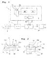
- Figure 1 shows an electrical current fed circuit arrangement 1, illustrated here with a voltage source "V” intended to supply a closed direct current circuit with a current "I”.
- circuit arrangement or a sensor body 2 in accordance with the specifications of the invention, coordinated with control equipment or a control circuit 5, designable in compliance with the basic preconditions for the second category of fuse units and incorporated in a switch unit 23 with an electric circuit breaker 3.
- the circuit arrangement or sensor body 2 comprises a temperature sensing sensor unit 22, whose nature and function will be more closely described below.
- the sensor body 2 is connected to control equipment or a control circuit 5, via a connection bus 2a, which is equipped for its function with circuits, circuit arrangements, modules and a processor unit, with allocated memories of as such in principle known type.
- the circuit arrangement 1 is illustrated here as an arrangement working on direct current (+) (-), but can of course in known fashion be adapted for alternating current.
- the present invention comprises a temperature sensitive circuit arrangement or a sensor body 2, in which this arrangement 1 comprises: a sensor unit 22 adapted to sense temperature; a first circuit arrangement 5a connected to the sensor unit, to be able to determine an instantaneously occurring temperature; a sensor body, in the form of a semiconductor 24, through which an electric current can flow and heatable by instantaneous current values; among other things a part of the base plate absorbing the heat energy generated in the sensor body 2 and/or one or more cooling bodies 32, 42, to which heat energy is adapted to be transferred.
- this arrangement 1 comprises: a sensor unit 22 adapted to sense temperature; a first circuit arrangement 5a connected to the sensor unit, to be able to determine an instantaneously occurring temperature; a sensor body, in the form of a semiconductor 24, through which an electric current can flow and heatable by instantaneous current values; among other things a part of the base plate absorbing the heat energy generated in the sensor body 2 and/or one or more cooling bodies 32, 42, to which heat energy is adapted to be
- sensor body 2 With reference to Figures 2 and 3 , the design of sensor body 2 is illustrated in more detail.
- Sensor body 2 is related to the one (the inner, upper) surface length of the base plate 12 such that effective heat transfer will take place between the sensor element or semiconductor element 24 and the base plate 12, while the oppositely placed and other (outer, lower) surface length 12b is related to an adjacent cooling body 32 such that effective heat transfer will take place between the base plate 12 and the cooling body 32.
- Figure 4 illustrates that the other surface length 12b of the base plate must be allocated two separate surface areas: a first surface area 12b1, intended to cooperate with and create a heat transfer to the cooling body (32), in order thus to form a thermal coordination with a high thermal capacity, and a second surface area 12b2, intended to be free from direct cooperation with, and a direct heat transfer via heat pipe/conduction/conductor to, the cooling body (32), and that said sensor unit 22 is adapted to be in direct or indirect heat-transfer cooperation , via a plate 22a, with said second surface area 12b2 in that the sensor unit 22 is placed against the upper surface length 12a of the base plate 12.
- a first surface area 12b1 intended to cooperate with and create a heat transfer to the cooling body (32), in order thus to form a thermal coordination with a high thermal capacity
- a second surface area 12b2 intended to be free from direct cooperation with, and a direct heat transfer via heat pipe/conduction/conductor to, the cooling body (32), and that said sensor unit 22
- the sensor unit 22 here is adapted to cooperate with said heat transferring plate 22a, although with good heat conducting ability to the second surface area or surface length 12a, in order to create a low thermal capacity and good thermal heat conducting ability between the sensor body 24 and the sensor unit 22 via the base plate 12.
- this distance must be made as short as possible and with as large a heat transferring and heat conducting area as possible. It would be optimal to have the sensor unit 22 inserted in a shaped central hole (not shown) in the base plate 12 and/or in the cooling body 32 and in immediate connection to the sensor body 24.
- Said cooling body 32 is allocated a surface length which connects to, or at least substantially connects to, a chosen surface length for the base plate 12.
- the sensor unit 22 here is enclosed in a heat insulating layer 22b, such as air, thus not in direct contact with objects with good heat conducting ability, such as metal objects, in order to increase the thermal capacity.
- the first surface area 12b1 must be dimensioned for the largest possible surface expansion and the largest possible heat transferring or heat conducting contact area to the cooling body 32 or similar and must in practice be adapted to comprise at least 50% of the second surface length 12b of the base plate, typically about 80%.
- the high thermal capacity pertaining to the invention comprises then principally the first surface area 12b1 of the base plate and a cooling body 32 coordinated therewith, with an intervening foil 10.
- the dimensioning of the required high thermal capacity must therefore be adapted to the preconditions that must apply to allow the rapid transfer of excess heat generated by short circuit currents, during extremely short periods of time to the sensor unit 22.
- the effective heat transfer between the second surface length 12b of the base plate 12, and the cooling body (32) is adapted to take place via a heat conducting foil 10, according to Figure 4 .
- this sensor body 2 must comprise a sensor body unit 2', which is connected in series to the feed current "I" via the wires "L1" and “L2” and connector pins 6, 7 or similar belonging to them and which the sensor body unit 2', includes a set of semiconductor elements 24, which allow heat to be produced depending on the instantaneous (or mean value forming) value of a feed current "I" passing through it
- the sensor body unit 2' is directly mounted on and resting on the base plate 12 and with the heat generating semiconductor elements 24 oriented very dose to upper area 12a of the base plate 12 for a direct transfer of generated heat via a /heat conductor/heat pipe/heat conduction to the first surface area 12b1 of the base plate 12.
- the thin heat conducting foil 10 Located between the base plate 12 of the sensor body 2 and one or more cooling bodies 32, 34 is the thin heat conducting foil 10, but with a adapted cutout 11 to be able to cooperate with the plate 22a for the sensor unit 22.
- the sensor body 2 with semiconductor unit 24 is attached to the base plate 12 in such a way that effective heat conduction occurs between the unit 24 and the base plate 12 via as large a surface extension as is practicable.
- the sensor unit 22 must be oriented close to, and preferably in a cutout in, the base plate 12 to minimize the heat conducting distance and thereby offer an accurate and rapid temperature measurement.
- the invention specifies more particularly that the effective heat conduction of excess heat must be adapted to take place via an inherently soft and heat conducting foil 10.
- said sensor unit 22 is fixed to the base plate 12 in such a way that effective heat conduction takes place concentrated between the sensor unit 22 and the base plate 12 and in which a temperature difference between the heat generating chip(s) with transistors 24a of the sensor body unit 2'and its elements 24, via the base plate 12 and the sensor unit 22, can be kept as small as possible.
- Said cutout 11 is illustrated here related to the edge of said foil 10 and said cutout 11 displays a divergent shape, with regard to its boundary surfaces 11a, 11b (See Figure 4 ).
- Said cutout 11 is furthermore shown here adapted such that said sensor unit 22 with its plate 22a can be oriented very dose to a silicon plate or corresponding chip or transistor 24a, heatable by the electric current.
- Said foil 10 chosen here is a copper foil, with a surface length which effectively transports heat from the base plate 12 to the cooling body 32, and keeps separate/separates the sensor unit 22 from the foil 10 and/or cooling body 32.
- Said foil 10 is adjusted to a low heat storing capacity and a good heat conducting ability and said base plate 12 is adjusted to a higher heat storing capacity and a good heat conducting ability.
- the heat storing capacity allocated in the foil 10 and the heat storing capacity allocated in the base plate 12 must together be adjusted lower than the capacity stored in cooling body 32 and/or 34, with an intervening foil 10'.
- Said sensor unit 22 must then include one or more semiconductor elements 24, such as MOSFET transistors 24a, IGBT transistors, thyristors and/or other transistors and their arrangements.
- semiconductor elements 24 such as MOSFET transistors 24a, IGBT transistors, thyristors and/or other transistors and their arrangements.
- a temperature dependent output signal from said sensor unit 22 on a wire 2a is connected via control unit functions or control circuit related functions to a second circuit arrangement 5b, adapted to serve as a short circuit protection and break the current feed "I".
- the temperature dependent output signal 2a from said sensor unit 22 can also be connected to a third circuit arrangement 5c, adapted to serve as an overcurrent protection,
- Said control unit related circuit arrangement can then include a first module 5d, to determine and follow the instantaneous values of the temperature, according to Figure 5 .
- Said circuit arrangement can then include a second module 5e, to determine the value for the time derivative of a temperature (di/dt), illustrated in Figure 5 .
- Figure 5 illustrates schematically a heating curve in a temperature/time diagram, at a chosen temperature difference between the heat generating sensor body 24 and its element(s) and the temperature sensing sensor unit 22, which (temperature), in accordance with the specifications of the invention, must be kept as low as possible.
- Figure 5 is meant to illustrate that up to the point of time "t1" a small and constant heat emission from element 24 takes place, based on a normal current value "I".
- the excess heat separate from the actual temperature measurement must be distributed to the surface length of the base plate 12 via the surface length of the foil 10, to the cooling body 32, without appreciably affecting the temperature sensing of the sensor unit 22.
Landscapes
- Physics & Mathematics (AREA)
- General Physics & Mathematics (AREA)
- Cooling Or The Like Of Semiconductors Or Solid State Devices (AREA)
- Measuring Temperature Or Quantity Of Heat (AREA)
Applications Claiming Priority (1)
| Application Number | Priority Date | Filing Date | Title |
|---|---|---|---|
| SE0801664A SE532651C2 (sv) | 2008-07-10 | 2008-07-10 | Ett för en momentan temperatur känsligt och temperaturen fastställande, arrangemang |
Publications (2)
| Publication Number | Publication Date |
|---|---|
| EP2144046A2 true EP2144046A2 (de) | 2010-01-13 |
| EP2144046A3 EP2144046A3 (de) | 2012-06-06 |
Family
ID=41211682
Family Applications (1)
| Application Number | Title | Priority Date | Filing Date |
|---|---|---|---|
| EP09161753A Withdrawn EP2144046A3 (de) | 2008-07-10 | 2009-06-03 | Temperaturempfindliche und Temperatur bestimmende Anordnung |
Country Status (2)
| Country | Link |
|---|---|
| EP (1) | EP2144046A3 (de) |
| SE (1) | SE532651C2 (de) |
Family Cites Families (2)
| Publication number | Priority date | Publication date | Assignee | Title |
|---|---|---|---|---|
| DE4020304A1 (de) * | 1990-06-26 | 1992-01-02 | Siemens Ag | Anordnung zur temperaturmessung an gekuehlten elektronischen bauelementen |
| DE19708653C2 (de) * | 1997-03-04 | 1999-07-08 | Telefunken Microelectron | Vorrichtung zur Bestimmung der Temperatur mindestens eines auf einem Trägerkörper mit geringer Wärmeleitfähigkeit angeordneten Halbleiterbauelements |
-
2008
- 2008-07-10 SE SE0801664A patent/SE532651C2/sv not_active IP Right Cessation
-
2009
- 2009-06-03 EP EP09161753A patent/EP2144046A3/de not_active Withdrawn
Also Published As
| Publication number | Publication date |
|---|---|
| SE532651C2 (sv) | 2010-03-09 |
| SE0801664L (sv) | 2010-01-11 |
| EP2144046A3 (de) | 2012-06-06 |
Similar Documents
| Publication | Publication Date | Title |
|---|---|---|
| US9338926B2 (en) | Cooling structure for electronic circuit component and inverter apparatus using the same | |
| US6504697B1 (en) | Arrangement and method for measuring a temperature | |
| US7684165B2 (en) | Circuit element and method for protecting a load circuit | |
| CA2803296A1 (en) | Secondary thermal sensor for primary conductors | |
| US6100745A (en) | Combination positive temperature coefficient resistor and metal-oxide semiconductor field-effect transistor devices | |
| US20180048141A1 (en) | Power module | |
| US9249961B2 (en) | Light-emitting device | |
| KR20200025910A (ko) | 불량 모드 감지를 통한 퓨즈 제어 시스템 및 방법 | |
| JP2011199161A (ja) | 半導体装置 | |
| JP6544805B2 (ja) | 保護回路 | |
| CN103380555B (zh) | 保护装置 | |
| EP2144046A2 (de) | Temperaturempfindliche und Temperatur bestimmende Anordnung | |
| US11817694B2 (en) | Protection element and protection circuit for a battery | |
| CN103003905A (zh) | 具有散热装置的开关设备 | |
| JP2009117535A (ja) | ソリッドステートリレーおよびこれを搭載した電子機器 | |
| US20150288357A1 (en) | Semiconductor device | |
| KR20250125943A (ko) | 회로 차단기용 열 관리 장치 | |
| CA3209542A1 (en) | Heat sink for a solid-state circuit breaker in an electrical panel | |
| US20240274568A1 (en) | Package for use with integarted circuit | |
| CN223273272U (zh) | 一种功率mos封装结构 | |
| EP4362256A1 (de) | Flugzeugfestkörperleistungsregler und verfahren zur überwachung der temperatur eines festkörperschalters in einem flugzeugfestkörperleistungsregler | |
| JP5229506B2 (ja) | Dc−dcコンバータ用の半導体装置 | |
| KR102956332B1 (ko) | 배터리 팩 및 모니터링 회로 | |
| JP2023141445A (ja) | 電力変換装置 | |
| EP2378527A2 (de) | Überspannungsschutzvorrichtung |
Legal Events
| Date | Code | Title | Description |
|---|---|---|---|
| PUAI | Public reference made under article 153(3) epc to a published international application that has entered the european phase |
Free format text: ORIGINAL CODE: 0009012 |
|
| AK | Designated contracting states |
Kind code of ref document: A2 Designated state(s): AT BE BG CH CY CZ DE DK EE ES FI FR GB GR HR HU IE IS IT LI LT LU LV MC MK MT NL NO PL PT RO SE SI SK TR |
|
| PUAL | Search report despatched |
Free format text: ORIGINAL CODE: 0009013 |
|
| AK | Designated contracting states |
Kind code of ref document: A3 Designated state(s): AT BE BG CH CY CZ DE DK EE ES FI FR GB GR HR HU IE IS IT LI LT LU LV MC MK MT NL NO PL PT RO SE SI SK TR |
|
| RIC1 | Information provided on ipc code assigned before grant |
Ipc: G01K 1/16 20060101AFI20120503BHEP Ipc: G01K 7/42 20060101ALI20120503BHEP |
|
| STAA | Information on the status of an ep patent application or granted ep patent |
Free format text: STATUS: THE APPLICATION IS DEEMED TO BE WITHDRAWN |
|
| 18D | Application deemed to be withdrawn |
Effective date: 20121207 |