EP2143570A2 - Fahrzeugluftreifen - Google Patents
Fahrzeugluftreifen Download PDFInfo
- Publication number
- EP2143570A2 EP2143570A2 EP09159489A EP09159489A EP2143570A2 EP 2143570 A2 EP2143570 A2 EP 2143570A2 EP 09159489 A EP09159489 A EP 09159489A EP 09159489 A EP09159489 A EP 09159489A EP 2143570 A2 EP2143570 A2 EP 2143570A2
- Authority
- EP
- European Patent Office
- Prior art keywords
- monofilaments
- pneumatic vehicle
- tire according
- vehicle tire
- filament
- Prior art date
- Legal status (The legal status is an assumption and is not a legal conclusion. Google has not performed a legal analysis and makes no representation as to the accuracy of the status listed.)
- Granted
Links
Images

Classifications
-
- B—PERFORMING OPERATIONS; TRANSPORTING
- B60—VEHICLES IN GENERAL
- B60C—VEHICLE TYRES; TYRE INFLATION; TYRE CHANGING; CONNECTING VALVES TO INFLATABLE ELASTIC BODIES IN GENERAL; DEVICES OR ARRANGEMENTS RELATED TO TYRES
- B60C9/00—Reinforcements or ply arrangement of pneumatic tyres
- B60C9/18—Structure or arrangement of belts or breakers, crown-reinforcing or cushioning layers
- B60C9/20—Structure or arrangement of belts or breakers, crown-reinforcing or cushioning layers built-up from rubberised plies each having all cords arranged substantially parallel
-
- B—PERFORMING OPERATIONS; TRANSPORTING
- B60—VEHICLES IN GENERAL
- B60C—VEHICLE TYRES; TYRE INFLATION; TYRE CHANGING; CONNECTING VALVES TO INFLATABLE ELASTIC BODIES IN GENERAL; DEVICES OR ARRANGEMENTS RELATED TO TYRES
- B60C9/00—Reinforcements or ply arrangement of pneumatic tyres
- B60C9/0057—Reinforcements comprising preshaped elements, e.g. undulated or zig-zag filaments
-
- B—PERFORMING OPERATIONS; TRANSPORTING
- B60—VEHICLES IN GENERAL
- B60C—VEHICLE TYRES; TYRE INFLATION; TYRE CHANGING; CONNECTING VALVES TO INFLATABLE ELASTIC BODIES IN GENERAL; DEVICES OR ARRANGEMENTS RELATED TO TYRES
- B60C9/00—Reinforcements or ply arrangement of pneumatic tyres
- B60C9/0064—Reinforcements comprising monofilaments
Definitions
- the invention relates to a pneumatic vehicle tire with a radial carcass, with a radially above the carcass arranged tread and with a belt which is arranged between carcass and tread and which has at least one layer of embedded in rubber, mutually parallel monofilaments, wherein at least two monofilaments another filament is wrapped in a helical shape.
- Pneumatic vehicle tires in particular radial tires, require support of other tire components during driving to absorb, in particular, lateral forces during cornering as well as circumferential forces during acceleration. Because the carcass construction of a radial tire has radially extending strength carrier, which can absorb the forces occurring during driving only inadequate. This supporting task is performed i.a. the belt.
- Multi-layered belt constructions are known, which consist of two intersecting layers of oppositely rising, at an acute angle extending reinforcement and which are optionally stabilized by a bandage.
- the reinforcements of the two belt plies are usually steel cords consisting of twisted steel filaments twisted to a cord. Steel cords require a high material usage, whereby the weight and the manufacturing cost of the tire are increased.
- monofilaments are used instead of the steel cords as belt resistance, thereby saving material and the production costs be lowered.
- the problem with the use of monofilaments as belt resistance carriers is that they have to be stretchable as well as able to be stressed on compressions without breakage. Otherwise, the tire having the belt layer containing these reinforcements would be undesirably reduced in durability.
- a generic pneumatic vehicle tire with a belt having monofilaments as strength carrier is known, for example, from US Pat DE 4212846 C2 known.
- the reinforcements are monofilaments with a round cross-section. Two monofilaments in each case are arranged directly adjacent to one another and wound in a helical manner by an outer filament. However, the monofilaments just formed parallel to their longitudinal axis are not satisfactorily compressible.
- the object is achieved by arranging the at least two monofilaments wrapped by a further filament at a distance from one another and in that the helical wrapping is formed by the further filament such that the monofilaments are arranged undulating (wave-shaped) such that the amplitudes are approximately in radial direction.
- the at least two helically wound monofilaments, which form a reinforcement are arranged at a distance from one another.
- the wrapping is such that the monofilaments are arranged in a 2-D waveform in the belt, the amplitudes being approximately in the radial direction of the tire. Due to this spacing of the monofilaments and their undulating configuration, the strength element can be subjected to good pressure and tension. It is provided in spite of the use of monofilaments as a strength carrier within the belt layer, a durable pneumatic vehicle tire, the cost in its production. In addition, the rubber penetration of the strength member is very good, whereby the rubber-strength support connection is improved, whereby the durability of the tire is also positively influenced.
- the helical wrapping of the at least two monofilaments is in the form of eighth in the belt ply, with one monofilament in the left circular arc of the eight and the other monofilament in the right circular arc of the figure eight.
- a flat strength member is provided, through which the belt layer can be made thin.
- the monofilaments consist of steel or its alloys or consist of polymer with a glass temperature greater than 40 ° C., preferably of polyester.
- the monofilaments can have different cross sections. It is expedient to have a circular or oval cross section. If the cross section is oval, then the strength member is located in the belt layer, so that the largest diameter of the oval is aligned parallel to the belt position.
- the further filament can have a circular, an oval or a flat cross-section. It is advantageous if the further filament consists of steel or its alloys or if the further filament is a polymer having a glass temperature greater than 40 ° C., preferably of polyester.
- the monofilaments have a diameter of 0.15-0.50 mm and / or the diameter of the further filament is between 0.10 and 0.35 mm and / or the smallest distance between the monofilaments wound with the further filament is 0.20 mm ,
- the Fig. 1 shows the right half of a cross-section through a pneumatic radial tire 1.
- the tire 1 consists of side walls 2, of a carcass 3 extending from one bead area 4 to the other bead area 4 and from axially inside to axially outward around bead cores 5 and the bead cores 5 seated bead core profiles 6 is guided around as Karkassrochschlag 3a, from a radially above the carcass 3 arranged tread 7 and a single-ply belt 8, which is arranged between the carcass 3 and 7 tread radially below the tread 7.
- the belt 8 consists of a layer of rubber 10 embedded reinforcements 9, which are aligned with their longitudinal axes 11 in the circumferential direction of the tire.
- the reinforcements 9 consist of two mutually parallel and spaced monofilaments 10, which are wound by a further filament 11 so helically, so that the monofilaments 10 2-D undulating (wave-shaped) are arranged such that the amplitudes 15 approximately in radial direction.
- the carcass 3 can be designed in a conventional and known manner and thus have embedded in a rubber compound, extending in the radial direction reinforcing threads of a textile material or steel cord.
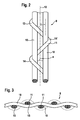
- the Fig. 2 shows the strength member 9 in three-dimensional view in a preferred embodiment, in which the strength member 9 in a belt 8 of the in Fig. 1 described vehicle pneumatic tire 1 can be used.
- the Figure 3 shows a section along the longitudinal axis of the reinforcement of the Fig.2 ,
- the reinforcement 9 has two monofilaments 10, which are arranged parallel and spaced from each other and which are wrapped by another filament 11.
- the helical wrapping 13 is formed by the further filament 11 such that the monofilaments 10 are arranged undulating (wavy), such that the amplitudes 15 extend approximately in the radial direction in the tire.
- the helical wrapping 13 of the two monofilaments 10 has the shape of in the belt layer lying undulating eighth, wherein a monofilament 10 in the left circular arc 14 of the eight and the other monofilament in the right circular arc 14 'of the eight is arranged.
- the monofilaments 10 have a round cross section, while the other filament 11 has an oval cross section.
- the additional filament 11 converts the monofilaments 10 in such a way that the largest diameter of the oval cross-section of the further filament 11 extends approximately parallel to the reinforcement longitudinal axis 12.
- the reinforcement 9 is made of steel.
- the spacing a between the two monofilaments 10 of a strength member is the shortest distance of the facing monofilament surfaces and is 0.25 mm.
- the cross-sectional area of the monofilaments 10 is 0.07 mm 2 and the cross-sectional area of the further filament 11 is 0.18 mm 2 .
- the angle ⁇ which describes the pitch of the helical weave of the further filament 11 with respect to the longitudinal extent of the monofilament 10, is 30 °.
- the monofilaments 10 are arranged undulating (wavy) by the helical wrapping of the further filament 11, such that the amplitudes extend approximately in the radial direction of the tire.
- the wave motion of the two monofilaments 10 of the reinforcing member 9 is in opposite directions.
Landscapes
- Engineering & Computer Science (AREA)
- Mechanical Engineering (AREA)
- Tires In General (AREA)
Abstract
Description
- Die Erfindung betrifft einen Fahrzeugluftreifen mit einer Radialkarkasse, mit einem radial oberhalb der Karkasse angeordneten Laufstreifen und mit einem Gürtel, welcher zwischen Karkasse und Laufstreifen angeordnet ist und welcher wenigstens eine Lage aus in Gummi eingebettete, parallel zueinander angeordnete Monofilamente aufweist, wobei wenigstens zwei Monofilamente durch ein weiteres Filament in etwa wendelförmig umwickelt sind.
- Fahrzeugluftreifen, insbesondere Radialreifen, benötigen während des Fahrbetriebes zur Aufnahme von insbesondere Querkräften bei Kurvenfahrt sowie von Umfangskräften bei Beschleunigung Unterstützung von anderen Reifenbauteilen. Denn die Karkasskonstruktion eines Radialreifens weist radial verlaufende Festigkeitsträger auf, welche die im Fahrbetrieb auftretenden Kräfte nur unzureichend aufnehmen können. Diese unterstützende Aufgabe übernimmt u.a. der Gürtel. Bekannt sind mehrlagige Gürtelkonstruktionen, die aus zwei sich kreuzenden Lagen entgegengesetzt steigender, unter einem spitzen Winkel verlaufender Festigkeitsträger bestehen und welche optional durch eine Bandage stabilisiert werden. Die Festigkeitsträger der zwei Gürtellagen sind üblicherweise Stahlcorde, welche aus verzwirnten Stahlfilamenten bestehen, welche zu einem Cord endverdreht sind. Stahlcorde erfordern einen hohen Materialeinsatz, wodurch das Gewicht und die Herstellungskosten des Reifens erhöht sind.
- Die Bestrebungen der Reifenentwicklung gehen jedoch dahin, die Herstellungskosten des Reifens zu senken und am Gewicht des Reifens einzusparen.
- Aus diesem Grund werden Monofilamente anstatt der Stahlcorde als Gürtelfestigkeitsträger eingesetzt, wodurch Material eingespart und die Herstellungskosten gesenkt werden. Problematisch an dem Einsatz von Monofilamenten als Gürtelfestigkeitsträger ist jedoch, dass diese sowohl dehnbar, als auch auf Kompressionen ohne Bruch beanspruchbar sein müssen. Andernfalls wäre der Reifen, welcher diese Festigkeitsträger enthaltene Gürtellage aufweist, in seiner Haltbarkeit unerwünscht vermindert.
- Ein gattungsgemäßer Fahrzeugluftreifen mit einem Monofilamente als Festigkeitsträger aufweisenden Gürtel ist beispielsweise aus der
DE 4212846 C2 bekannt geworden. Die Festigkeitsträger sind Monofilamente mit einem runden Querschnitt. Jeweils zwei Monofilamente sind unmittelbar benachbart zueinander angeordnet und durch ein äußeres Filament wendelförmig umwickelt. Jedoch sind die parallel ihrer Längsachse gerade ausgebildeten Monofilamente nicht befriedigend auf Kompression beanspruchbar. - Es ist daher die Aufgabe der Erfindung, einen haltbaren Fahrzeugluftreifen mit einer Gürtelkonstruktion bereitzustellen, durch die gute Fahreigenschaften des Reifens ermöglicht sind, durch die das Gewicht des Reifens reduziert und der Materialeinsatz verringert ist.
- Die Aufgabe wird gelöst, indem die wenigstens zwei durch ein weiteres Filament umwickelten Monofilamente beabstandet zueinander angeordnet sind und dass die wendelförmige Umwickelung durch das weitere Filament derart ausgebildet ist, dass die Monofilamente undulierend (wellenförmig) angeordnet sind, derart, dass die Amplituden in etwa in radialer Richtung verlaufen.
- Erfindungswesentlich ist, dass die wenigstens zwei wendelförmig umwickelten Monofilamente, welche einen Festigkeitsträger bilden, beabstandet voneinander angeordnet sind. Erfindungsgemäß ist die Umwicklung derart, dass die Monofilamente in einer 2-D-Wellenform im Gürtel angeordnet sind, wobei die Amplituden in etwa in radialer Richtung des Reifens verlaufen. Durch diese Beabstandung der Monofilamente und durch deren wellenförmige Ausgestaltung ist der Festigkeitsträger auf Druck und Zug gut beanspruchbar. Es ist trotz des Einsatzes von Monofilamenten als Festigkeitsträger innerhalb der Gürtellage ein haltbarer Fahrzeugluftreifen bereitgestellt, der kostengünstig in seiner Herstellung ist. Zudem ist die Gummidurchdringung des Festigkeitsträgers sehr gut, wodurch die Gummi-Festigkeitsträgeranbindung verbessert ist, wodurch die Haltbarkeit des Reifens ebenfalls positiv beeinflusst ist.
- In einer bevorzugten Ausführungsform weist die wendelförmige Umwickelung der wenigstens zwei Monofilamente die Form von in der Gürtellage liegenden Achten auf, wobei ein Monofilament in dem linken Kreisbogen der Acht und das andere Monofilament in dem rechten Kreisbogen der Acht angeordnet ist. Hierdurch ist ein flacher Festigkeitsträger bereitgestellt, durch den die Gürtellage dünn ausgebildet sein kann.
- Vorteilhaft ist es, wenn die Monofilamente aus Stahl oder dessen Legierungen bestehen oder aus Polymer mit einer Glasstemperatur größer 40°C, vorzugsweise aus Polyester, bestehen.
- Die Monofilamente können verschiedene Querschnitte aufweisen. Zweckmäßig ist ein kreisrunder oder ein ovaler Querschnitt. Ist der Querschnitt oval, so liegt der Festigkeitsträger derart in der Gürtellage, so dass der größte Durchmesser des Ovals parallel zur Gürtellage ausgerichtet ist.
- Das weitere Filament kann einen kreisrunden, einen ovalen oder einen flachen Querschnitt aufweisen. Dabei ist es vorteilhaft, wenn das weitere Filament aus Stahl oder dessen Legierungen besteht oder wenn das weitere Filament ein Polymer mit einer Glasstemperatur größer 40°C, vorzugsweise aus Polyester, ist.
- Vorteilhafterweise weisen die Monofilamente einen Durchmesser von 0,15 - 0,50mm auf und/oder der Durchmesser des weiteren Filamentes beträgt zwischen 0,10 und 0,35mm und/oder der kleinste Abstand zwischen den mit dem weiteren Filament umwickelten Monofilamenten beträgt 0,20mm.
- Weitere Merkmale, Vorteile und Einzelheiten der Erfindung werden anhand der Zeichnungen, die schematische Ausführungsbeispiele darstellen, näher erläutert. Es zeigen die:
- Fig. 1
- einen Teilquerschnitt durch einen erfindungsgemäßen Radialluftreifen;
- Fig. 2
- einen Festigkeitsträger in dreidimensionaler Ansicht;
- Fig. 3
- den Festigkeitsträger der
Fig.2 im Längsschnitt. - Die
Fig. 1 zeigt die rechte Hälfte eines Querschnittes durch einen PKW-Radialluftreifen 1. Der Reifen 1 bestehend aus Seitenwänden 2, aus einer Karkasse 3, die sich von einem Wulstbereich 4 zum anderen Wulstbereich 4 erstreckt und von axial innen nach axial außen um Wulstkerne 5 und den Wulstkernen 5 aufsitzenden Wulstkernprofilen 6 als Karkasshochschlag 3a herumgeführt ist, aus einem radial oberhalb der Karkasse 3 angeordneten Laufstreifen 7 und aus einem einlagigen Gürtel 8, der zwischen Karkasse 3 und Laufstreifen 7 radial unterhalb des Laufstreifens 7 angeordnet ist. Der Gürtel 8 besteht aus einer Lage aus in Gummi 10 eingebetteten Festigkeitsträgern 9, welche mit ihren Längsachsen 11 in Umfangsrichtung des Reifens ausgerichtet sind. Die Festigkeitsträger 9 bestehen aus zwei parallel zueinander und voneinander beabstandeten Monofilamenten 10, welche durch ein weiteres Filament 11 derart wendelförmig umwickelt sind, so dass die Monofilamente 10 2-D-undulierend (wellenförmig) angeordnet sind, derart, dass die Amplituden 15 in etwa in radialer Richtung verlaufen. Hierdurch sind die Festigkeitsträger 9 dehnbar und komprimierbar. Die Karkasse 3 kann in herkömmlicher und bekannter Weise ausgeführt sein und somit in eine Gummimischung eingebettete, in radialer Richtung verlaufende Verstärkungsfäden aus einem textilen Material oder aus Stahlcord aufweisen. - Die
Fig. 2 zeigt den Festigkeitsträger 9 in dreidimensionaler Ansicht in einer bevorzugten Ausführungsform, in welcher der Festigkeitsträger 9 in einem Gürtel 8 des in derFig. 1 beschriebenen Fahrzeugluftreifen 1 einsetzbar ist. DieFig.3 zeigt einen Schnitt entlang der Längsachse des Festigkeitsträgers derFig.2 . Der Festigkeitsträger 9 weist zwei Monofilamente 10 auf, welche parallel und beabstandet zueinander angeordnet sind und welche durch ein weiteres Filament 11 umwickelten sind. Die wendelförmige Umwickelung 13 durch das weitere Filament 11 derart ausgebildet ist, dass die Monofilamente 10 undulierend (wellenförmig) angeordnet sind, derart, dass die Amplituden 15 in etwa in radialer Richtung im Reifen verlaufen. Die wendelförmige Umwickelung 13 der zwei Monofilamente 10 weist die Form von in der Gürtellage liegenden gewendelten Achten auf, wobei ein Monofilament 10 in dem linken Kreisbogen 14 der Acht und das andere Monofilament in dem rechten Kreisbogen 14' der Acht angeordnet ist. Die Monofilamente 10 weisen einen runden Querschnitt auf, während das weitere Filament 11 einen ovalen Querschnitt aufweist. Dabei umwendelt das weitere Filament 11 die Monofilamente 10 derart, dass der größte Durchmesser des ovalen Querschnittes des weiteren Filamentes 11 in etwa parallel zur Festigkeitsträgerlängsachse 12 erstreckt ist. Der Festigkeitsträger 9 besteht aus Stahl. Die Beabstandung a zwischen den beiden Monofilamenten 10 eines Festigkeitsträgers ist der kürzeste Abstand der einander zugewandten Monofilamentoberflächen und beträgt 0,25mm. Die Querschnittsfläche der Monofilamente 10 beträgt 0,07mm2 und die Querschnittsfläche des weiteren Filamentes 11 beträgt 0,18mm2. Der Winkel α, welcher die Steigung der wendelartigen Umflechtung des weiteren Filamentes 11 in Bezug auf die Längserstreckung des Monofilamentes 10 beschreibt, beträgt 30°. In derFig.3 ist zu erkennen, dass durch die wendelförmige Umwickelung des weiteren Filamentes 11 die Monofilamente 10 undulierend (wellenförmig) angeordnet sind, derart, dass die Amplituden in etwa in radialer Richtung des Reifens verlaufen. Dabei ist die Wellenbewegung der beiden Monofilamente 10 des Festigkeitsträgers 9 gegenläufig. -
- 1
- Reifen
- 2
- Seitenwand
- 3
- Karkasse
- 3a
- Karkasshochschlag
- 4
- Wulstbereich
- 5
- Wulstkern
- 6
- Wulstkernprofil
- 7
- Laufstreifen
- 8
- Gürtel
- 9
- Festigkeitsträger
- 10
- Monofilament
- 11
- Filament
- 12
- Längsachse des Festigkeitsträgers
- 13
- Wendelförmige Umwicklung
- 14
- linker Kreisbogen der Umwicklung
- 14'
- rechter Kreisbogen der Umwicklung
- 15
- Amplitude
- a
- Beabstandung
Claims (8)
- Fahrzeugluftreifen (1),
mit einer Radialkarkasse (3), mit einem radial oberhalb der Karkasse (3) angeordneten Laufstreifen (7) und mit einem Gürtel (8), welcher zwischen Karkasse (3) und Laufstreifen (7) angeordnet ist und welcher wenigstens eine Lage aus in Gummi (10) eingebettete, parallel zueinander angeordnete Monofilamente (10) aufweist, wobei wenigstens zwei Monofilamente (10) durch ein weiteres Filament in etwa wendelförmig umwickelt sind und eine Festigkeitsträger (9) bilden,
dadurch gekennzeichnet, dass die wenigstens zwei durch ein weiteres Filament (11) umwickelten Monofilamente (10) beabstandet zueinander angeordnet sind und dass die wendelförmige Umwickelung (13) durch das weitere Filament (11) derart ausgebildet ist, dass die Monofilamente (10) undulierend angeordnet sind, derart, dass die Amplituden 15 in etwa in radialer Richtung verlaufen. - Fahrzeugluftreifen nach Anspruch 1,
dadurch gekennzeichnet, dass die wendelförmige Umwickelung (13) der wenigstens zwei Monofilamente (10) die Form von in der Gürtellage liegenden Achten aufweist, wobei ein Monofilament (10) in dem linken Kreisbogen (14) der Acht und das andere Monofilament (10) in dem rechten Kreisbogen (14') der Acht angeordnet ist. - Fahrzeugluftreifen nach einem oder mehreren der vorangehenden Ansprüche,
dadurch gekennzeichnet, dass die Monofilamente (10) aus Stahl oder dessen Legierungen bestehen. - Fahrzeugluftreifen nach einem oder mehreren der vorangehenden Ansprüche 1 oder 2,
dadurch gekennzeichnet, dass die Monofilamente (10) aus Polymer mit einer Glasstemperatur größer 40°C, vorzugsweise aus Polyester, bestehen. - Fahrzeugluftreifen nach einem oder mehreren der vorangehenden Ansprüche,
dadurch gekennzeichnet, dass die Monofilamente (10) einen kreisrunden oder einen ovalen Querschnitt aufweisen. - Fahrzeugluftreifen nach einem oder mehreren der vorangehenden Ansprüche,
dadurch gekennzeichnet, dass das weitere Filament (11) einen kreisrunden, einen ovalen oder einen flachen Querschnitt aufweist. - Fahrzeugluftreifen nach Anspruch 6,
dadurch gekennzeichnet, dass das weitere Filament (11) aus Stahl oder dessen Legierungen besteht. - Fahrzeugluftreifen nach Anspruch 6,
dadurch gekennzeichnet, dass das weitere Filament (11) ein Polymer mit einer Glasstemperatur größer 40°C, vorzugsweise aus Polyester, ist.
Applications Claiming Priority (1)
| Application Number | Priority Date | Filing Date | Title |
|---|---|---|---|
| DE102008032384A DE102008032384A1 (de) | 2008-07-09 | 2008-07-09 | Fahrzeugluftreifen |
Publications (3)
| Publication Number | Publication Date |
|---|---|
| EP2143570A2 true EP2143570A2 (de) | 2010-01-13 |
| EP2143570A3 EP2143570A3 (de) | 2010-09-01 |
| EP2143570B1 EP2143570B1 (de) | 2011-11-16 |
Family
ID=41021069
Family Applications (1)
| Application Number | Title | Priority Date | Filing Date |
|---|---|---|---|
| EP09159489A Not-in-force EP2143570B1 (de) | 2008-07-09 | 2009-05-06 | Fahrzeugluftreifen |
Country Status (3)
| Country | Link |
|---|---|
| EP (1) | EP2143570B1 (de) |
| AT (1) | ATE533644T1 (de) |
| DE (1) | DE102008032384A1 (de) |
Cited By (1)
| Publication number | Priority date | Publication date | Assignee | Title |
|---|---|---|---|---|
| ITTO20120885A1 (it) * | 2012-10-10 | 2014-04-11 | Bridgestone Corp | Pneumatico provvisto di una cintura di battistrada ad elevata rigidezza laterale |
Citations (1)
| Publication number | Priority date | Publication date | Assignee | Title |
|---|---|---|---|---|
| DE4212846C2 (de) | 1992-04-16 | 1997-08-14 | Sp Reifenwerke Gmbh | Verstärkungscord für elastomere Erzeugnisse |
Family Cites Families (3)
| Publication number | Priority date | Publication date | Assignee | Title |
|---|---|---|---|---|
| US3273978A (en) * | 1962-05-09 | 1966-09-20 | Kleber Colombes | Reinforcing element |
| JP2796254B2 (ja) * | 1994-10-27 | 1998-09-10 | 住友ゴム工業株式会社 | ゴム付コードファブリックの緯糸長さ設定方法 |
| US5743975A (en) * | 1995-03-24 | 1998-04-28 | The Goodyear Tire & Rubber Company | Radial medium truck tire with organic polymer reinforced top belt or breaker |
-
2008
- 2008-07-09 DE DE102008032384A patent/DE102008032384A1/de not_active Withdrawn
-
2009
- 2009-05-06 EP EP09159489A patent/EP2143570B1/de not_active Not-in-force
- 2009-05-06 AT AT09159489T patent/ATE533644T1/de active
Patent Citations (1)
| Publication number | Priority date | Publication date | Assignee | Title |
|---|---|---|---|---|
| DE4212846C2 (de) | 1992-04-16 | 1997-08-14 | Sp Reifenwerke Gmbh | Verstärkungscord für elastomere Erzeugnisse |
Cited By (1)
| Publication number | Priority date | Publication date | Assignee | Title |
|---|---|---|---|---|
| ITTO20120885A1 (it) * | 2012-10-10 | 2014-04-11 | Bridgestone Corp | Pneumatico provvisto di una cintura di battistrada ad elevata rigidezza laterale |
Also Published As
| Publication number | Publication date |
|---|---|
| EP2143570A3 (de) | 2010-09-01 |
| EP2143570B1 (de) | 2011-11-16 |
| ATE533644T1 (de) | 2011-12-15 |
| DE102008032384A1 (de) | 2010-01-14 |
Similar Documents
| Publication | Publication Date | Title |
|---|---|---|
| EP2765333B1 (de) | Festigkeitsträgerlage für Fahrzeugluftreifen sowie für Antriebsriemen | |
| EP2999602B1 (de) | Fahrzeugluftreifen und verwendung eines garnes aus einem textilen material | |
| DE2513782A1 (de) | Fahrzeugreifen | |
| DE102014222306A1 (de) | Fahrzeugluftreifen aufweisend eine Karkasse | |
| DE102010038199A1 (de) | Fahrzeugluftreifen | |
| DE4409182A1 (de) | Festigkeitsträger für Fahrzeugreifen | |
| WO2016055189A1 (de) | Fahrzeugluftreifen aufweisend eine gürtelbandage | |
| EP3218210B1 (de) | Fahrzeugluftreifen | |
| DE112007003335T5 (de) | Verbessserte Gürtelstruktur für Kfz-Reifen | |
| WO2009053131A1 (de) | Fahrzeugluftreifen | |
| EP1284203B1 (de) | Fahrzeugluftreifen mit einer Gürtelbandage | |
| EP2765334B1 (de) | Festigkeitsträgerlage für Fahrzeugluftreifen sowie für Antriebsriemen | |
| DE602004013043T2 (de) | Fahrzeugreifen | |
| EP2113397A1 (de) | Festigkeitsträgerlage aus Hybridcorden für elastomere Erzeugnisse, insbesondere für die Gürtelbandage von Fahrzeugluftreifen | |
| EP2143570B1 (de) | Fahrzeugluftreifen | |
| DE102018213780A1 (de) | Fahrzeugluftreifen | |
| EP2682281B1 (de) | Fahrzeugluftreifen | |
| EP2682279B1 (de) | Fahrzeugluftreifen | |
| EP1982849B1 (de) | Fahrzeugluftreifen mit Notlaufeigenschaften | |
| DE102004059771B4 (de) | Fahrzeugluftreifen und Verfahren zur Herstellung | |
| DE102016204924A1 (de) | Fahrzeugluftreifen | |
| DE102007009101B4 (de) | Fahrzeugluftreifen | |
| WO2017080692A1 (de) | Fahrzeugluftreifen | |
| EP1816012B1 (de) | Fahrzeugnotlaufreifen mit Seitenwandverstärkungsprofilen und Verfahren zur Herstellung der Profile | |
| DE102008032383B4 (de) | Fahrzeugluftreifen |
Legal Events
| Date | Code | Title | Description |
|---|---|---|---|
| PUAI | Public reference made under article 153(3) epc to a published international application that has entered the european phase |
Free format text: ORIGINAL CODE: 0009012 |
|
| AK | Designated contracting states |
Kind code of ref document: A2 Designated state(s): AT BE BG CH CY CZ DE DK EE ES FI FR GB GR HR HU IE IS IT LI LT LU LV MC MK MT NL NO PL PT RO SE SI SK TR |
|
| PUAL | Search report despatched |
Free format text: ORIGINAL CODE: 0009013 |
|
| AK | Designated contracting states |
Kind code of ref document: A3 Designated state(s): AT BE BG CH CY CZ DE DK EE ES FI FR GB GR HR HU IE IS IT LI LT LU LV MC MK MT NL NO PL PT RO SE SI SK TR |
|
| AX | Request for extension of the european patent |
Extension state: AL BA RS |
|
| 17P | Request for examination filed |
Effective date: 20110301 |
|
| RIC1 | Information provided on ipc code assigned before grant |
Ipc: B60C 9/20 20060101AFI20110429BHEP Ipc: B60C 9/00 20060101ALI20110429BHEP |
|
| GRAP | Despatch of communication of intention to grant a patent |
Free format text: ORIGINAL CODE: EPIDOSNIGR1 |
|
| GRAS | Grant fee paid |
Free format text: ORIGINAL CODE: EPIDOSNIGR3 |
|
| GRAA | (expected) grant |
Free format text: ORIGINAL CODE: 0009210 |
|
| AK | Designated contracting states |
Kind code of ref document: B1 Designated state(s): AT BE BG CH CY CZ DE DK EE ES FI FR GB GR HR HU IE IS IT LI LT LU LV MC MK MT NL NO PL PT RO SE SI SK TR |
|
| REG | Reference to a national code |
Ref country code: GB Ref legal event code: FG4D Free format text: NOT ENGLISH |
|
| REG | Reference to a national code |
Ref country code: CH Ref legal event code: EP |
|
| REG | Reference to a national code |
Ref country code: IE Ref legal event code: FG4D Free format text: LANGUAGE OF EP DOCUMENT: GERMAN |
|
| REG | Reference to a national code |
Ref country code: DE Ref legal event code: R096 Ref document number: 502009001935 Country of ref document: DE Effective date: 20120112 |
|
| REG | Reference to a national code |
Ref country code: NL Ref legal event code: VDEP Effective date: 20111116 |
|
| LTIE | Lt: invalidation of european patent or patent extension |
Effective date: 20111116 |
|
| PG25 | Lapsed in a contracting state [announced via postgrant information from national office to epo] |
Ref country code: NO Free format text: LAPSE BECAUSE OF FAILURE TO SUBMIT A TRANSLATION OF THE DESCRIPTION OR TO PAY THE FEE WITHIN THE PRESCRIBED TIME-LIMIT Effective date: 20120216 Ref country code: LT Free format text: LAPSE BECAUSE OF FAILURE TO SUBMIT A TRANSLATION OF THE DESCRIPTION OR TO PAY THE FEE WITHIN THE PRESCRIBED TIME-LIMIT Effective date: 20111116 Ref country code: IS Free format text: LAPSE BECAUSE OF FAILURE TO SUBMIT A TRANSLATION OF THE DESCRIPTION OR TO PAY THE FEE WITHIN THE PRESCRIBED TIME-LIMIT Effective date: 20120316 |
|
| PG25 | Lapsed in a contracting state [announced via postgrant information from national office to epo] |
Ref country code: GR Free format text: LAPSE BECAUSE OF FAILURE TO SUBMIT A TRANSLATION OF THE DESCRIPTION OR TO PAY THE FEE WITHIN THE PRESCRIBED TIME-LIMIT Effective date: 20120217 Ref country code: SE Free format text: LAPSE BECAUSE OF FAILURE TO SUBMIT A TRANSLATION OF THE DESCRIPTION OR TO PAY THE FEE WITHIN THE PRESCRIBED TIME-LIMIT Effective date: 20111116 Ref country code: PT Free format text: LAPSE BECAUSE OF FAILURE TO SUBMIT A TRANSLATION OF THE DESCRIPTION OR TO PAY THE FEE WITHIN THE PRESCRIBED TIME-LIMIT Effective date: 20120316 Ref country code: LV Free format text: LAPSE BECAUSE OF FAILURE TO SUBMIT A TRANSLATION OF THE DESCRIPTION OR TO PAY THE FEE WITHIN THE PRESCRIBED TIME-LIMIT Effective date: 20111116 Ref country code: HR Free format text: LAPSE BECAUSE OF FAILURE TO SUBMIT A TRANSLATION OF THE DESCRIPTION OR TO PAY THE FEE WITHIN THE PRESCRIBED TIME-LIMIT Effective date: 20111116 Ref country code: PL Free format text: LAPSE BECAUSE OF FAILURE TO SUBMIT A TRANSLATION OF THE DESCRIPTION OR TO PAY THE FEE WITHIN THE PRESCRIBED TIME-LIMIT Effective date: 20111116 Ref country code: NL Free format text: LAPSE BECAUSE OF FAILURE TO SUBMIT A TRANSLATION OF THE DESCRIPTION OR TO PAY THE FEE WITHIN THE PRESCRIBED TIME-LIMIT Effective date: 20111116 Ref country code: SI Free format text: LAPSE BECAUSE OF FAILURE TO SUBMIT A TRANSLATION OF THE DESCRIPTION OR TO PAY THE FEE WITHIN THE PRESCRIBED TIME-LIMIT Effective date: 20111116 |
|
| REG | Reference to a national code |
Ref country code: IE Ref legal event code: FD4D |
|
| PG25 | Lapsed in a contracting state [announced via postgrant information from national office to epo] |
Ref country code: CY Free format text: LAPSE BECAUSE OF FAILURE TO SUBMIT A TRANSLATION OF THE DESCRIPTION OR TO PAY THE FEE WITHIN THE PRESCRIBED TIME-LIMIT Effective date: 20111116 |
|
| PG25 | Lapsed in a contracting state [announced via postgrant information from national office to epo] |
Ref country code: IE Free format text: LAPSE BECAUSE OF FAILURE TO SUBMIT A TRANSLATION OF THE DESCRIPTION OR TO PAY THE FEE WITHIN THE PRESCRIBED TIME-LIMIT Effective date: 20111116 Ref country code: DK Free format text: LAPSE BECAUSE OF FAILURE TO SUBMIT A TRANSLATION OF THE DESCRIPTION OR TO PAY THE FEE WITHIN THE PRESCRIBED TIME-LIMIT Effective date: 20111116 Ref country code: EE Free format text: LAPSE BECAUSE OF FAILURE TO SUBMIT A TRANSLATION OF THE DESCRIPTION OR TO PAY THE FEE WITHIN THE PRESCRIBED TIME-LIMIT Effective date: 20111116 Ref country code: SK Free format text: LAPSE BECAUSE OF FAILURE TO SUBMIT A TRANSLATION OF THE DESCRIPTION OR TO PAY THE FEE WITHIN THE PRESCRIBED TIME-LIMIT Effective date: 20111116 Ref country code: BG Free format text: LAPSE BECAUSE OF FAILURE TO SUBMIT A TRANSLATION OF THE DESCRIPTION OR TO PAY THE FEE WITHIN THE PRESCRIBED TIME-LIMIT Effective date: 20120216 Ref country code: CZ Free format text: LAPSE BECAUSE OF FAILURE TO SUBMIT A TRANSLATION OF THE DESCRIPTION OR TO PAY THE FEE WITHIN THE PRESCRIBED TIME-LIMIT Effective date: 20111116 |
|
| PG25 | Lapsed in a contracting state [announced via postgrant information from national office to epo] |
Ref country code: IT Free format text: LAPSE BECAUSE OF FAILURE TO SUBMIT A TRANSLATION OF THE DESCRIPTION OR TO PAY THE FEE WITHIN THE PRESCRIBED TIME-LIMIT Effective date: 20111116 Ref country code: RO Free format text: LAPSE BECAUSE OF FAILURE TO SUBMIT A TRANSLATION OF THE DESCRIPTION OR TO PAY THE FEE WITHIN THE PRESCRIBED TIME-LIMIT Effective date: 20111116 |
|
| PLBE | No opposition filed within time limit |
Free format text: ORIGINAL CODE: 0009261 |
|
| STAA | Information on the status of an ep patent application or granted ep patent |
Free format text: STATUS: NO OPPOSITION FILED WITHIN TIME LIMIT |
|
| 26N | No opposition filed |
Effective date: 20120817 |
|
| BERE | Be: lapsed |
Owner name: CONTINENTAL REIFEN DEUTSCHLAND G.M.B.H. Effective date: 20120531 |
|
| REG | Reference to a national code |
Ref country code: DE Ref legal event code: R097 Ref document number: 502009001935 Country of ref document: DE Effective date: 20120817 |
|
| PG25 | Lapsed in a contracting state [announced via postgrant information from national office to epo] |
Ref country code: MC Free format text: LAPSE BECAUSE OF NON-PAYMENT OF DUE FEES Effective date: 20120531 |
|
| PG25 | Lapsed in a contracting state [announced via postgrant information from national office to epo] |
Ref country code: BE Free format text: LAPSE BECAUSE OF NON-PAYMENT OF DUE FEES Effective date: 20120531 Ref country code: MK Free format text: LAPSE BECAUSE OF FAILURE TO SUBMIT A TRANSLATION OF THE DESCRIPTION OR TO PAY THE FEE WITHIN THE PRESCRIBED TIME-LIMIT Effective date: 20111116 |
|
| PG25 | Lapsed in a contracting state [announced via postgrant information from national office to epo] |
Ref country code: ES Free format text: LAPSE BECAUSE OF FAILURE TO SUBMIT A TRANSLATION OF THE DESCRIPTION OR TO PAY THE FEE WITHIN THE PRESCRIBED TIME-LIMIT Effective date: 20120227 |
|
| PG25 | Lapsed in a contracting state [announced via postgrant information from national office to epo] |
Ref country code: FI Free format text: LAPSE BECAUSE OF FAILURE TO SUBMIT A TRANSLATION OF THE DESCRIPTION OR TO PAY THE FEE WITHIN THE PRESCRIBED TIME-LIMIT Effective date: 20111116 |
|
| PG25 | Lapsed in a contracting state [announced via postgrant information from national office to epo] |
Ref country code: MT Free format text: LAPSE BECAUSE OF FAILURE TO SUBMIT A TRANSLATION OF THE DESCRIPTION OR TO PAY THE FEE WITHIN THE PRESCRIBED TIME-LIMIT Effective date: 20111116 |
|
| REG | Reference to a national code |
Ref country code: CH Ref legal event code: PL |
|
| GBPC | Gb: european patent ceased through non-payment of renewal fee |
Effective date: 20130506 |
|
| PG25 | Lapsed in a contracting state [announced via postgrant information from national office to epo] |
Ref country code: LI Free format text: LAPSE BECAUSE OF NON-PAYMENT OF DUE FEES Effective date: 20130531 Ref country code: CH Free format text: LAPSE BECAUSE OF NON-PAYMENT OF DUE FEES Effective date: 20130531 |
|
| PG25 | Lapsed in a contracting state [announced via postgrant information from national office to epo] |
Ref country code: GB Free format text: LAPSE BECAUSE OF NON-PAYMENT OF DUE FEES Effective date: 20130506 Ref country code: TR Free format text: LAPSE BECAUSE OF FAILURE TO SUBMIT A TRANSLATION OF THE DESCRIPTION OR TO PAY THE FEE WITHIN THE PRESCRIBED TIME-LIMIT Effective date: 20111116 |
|
| PG25 | Lapsed in a contracting state [announced via postgrant information from national office to epo] |
Ref country code: LU Free format text: LAPSE BECAUSE OF NON-PAYMENT OF DUE FEES Effective date: 20120506 |
|
| PG25 | Lapsed in a contracting state [announced via postgrant information from national office to epo] |
Ref country code: HU Free format text: LAPSE BECAUSE OF FAILURE TO SUBMIT A TRANSLATION OF THE DESCRIPTION OR TO PAY THE FEE WITHIN THE PRESCRIBED TIME-LIMIT Effective date: 20090506 |
|
| REG | Reference to a national code |
Ref country code: FR Ref legal event code: PLFP Year of fee payment: 7 |
|
| REG | Reference to a national code |
Ref country code: AT Ref legal event code: MM01 Ref document number: 533644 Country of ref document: AT Kind code of ref document: T Effective date: 20140506 |
|
| PG25 | Lapsed in a contracting state [announced via postgrant information from national office to epo] |
Ref country code: AT Free format text: LAPSE BECAUSE OF NON-PAYMENT OF DUE FEES Effective date: 20140506 |
|
| REG | Reference to a national code |
Ref country code: FR Ref legal event code: PLFP Year of fee payment: 8 |
|
| REG | Reference to a national code |
Ref country code: FR Ref legal event code: PLFP Year of fee payment: 9 |
|
| REG | Reference to a national code |
Ref country code: FR Ref legal event code: PLFP Year of fee payment: 10 |
|
| PGFP | Annual fee paid to national office [announced via postgrant information from national office to epo] |
Ref country code: DE Payment date: 20230531 Year of fee payment: 15 |
|
| REG | Reference to a national code |
Ref country code: DE Ref legal event code: R081 Ref document number: 502009001935 Country of ref document: DE Owner name: CONTINENTAL REIFEN DEUTSCHLAND GMBH, DE Free format text: FORMER OWNER: CONTINENTAL REIFEN DEUTSCHLAND GMBH, 30165 HANNOVER, DE |
|
| PGFP | Annual fee paid to national office [announced via postgrant information from national office to epo] |
Ref country code: FR Payment date: 20240529 Year of fee payment: 16 |
|
| REG | Reference to a national code |
Ref country code: DE Ref legal event code: R119 Ref document number: 502009001935 Country of ref document: DE |
|
| PG25 | Lapsed in a contracting state [announced via postgrant information from national office to epo] |
Ref country code: DE Free format text: LAPSE BECAUSE OF NON-PAYMENT OF DUE FEES Effective date: 20241203 |
|
| PG25 | Lapsed in a contracting state [announced via postgrant information from national office to epo] |
Ref country code: FR Free format text: LAPSE BECAUSE OF NON-PAYMENT OF DUE FEES Effective date: 20250531 |