EP2143550B1 - Device for manufacturing hollow bodies from thermoplastic reformable plastic films - Google Patents
Device for manufacturing hollow bodies from thermoplastic reformable plastic films Download PDFInfo
- Publication number
- EP2143550B1 EP2143550B1 EP09006372A EP09006372A EP2143550B1 EP 2143550 B1 EP2143550 B1 EP 2143550B1 EP 09006372 A EP09006372 A EP 09006372A EP 09006372 A EP09006372 A EP 09006372A EP 2143550 B1 EP2143550 B1 EP 2143550B1
- Authority
- EP
- European Patent Office
- Prior art keywords
- moulding table
- toggle lever
- pivoting
- moulding
- rollers
- Prior art date
- Legal status (The legal status is an assumption and is not a legal conclusion. Google has not performed a legal analysis and makes no representation as to the accuracy of the status listed.)
- Active
Links
- 239000002985 plastic film Substances 0.000 title claims description 4
- 229920006255 plastic film Polymers 0.000 title claims description 4
- 238000004519 manufacturing process Methods 0.000 title claims 2
- 229920001169 thermoplastic Polymers 0.000 title 1
- 239000004416 thermosoftening plastic Substances 0.000 title 1
- 238000000465 moulding Methods 0.000 claims description 17
- 238000004080 punching Methods 0.000 claims description 4
- 238000007493 shaping process Methods 0.000 abstract description 2
- 238000003856 thermoforming Methods 0.000 description 5
- 210000003127 knee Anatomy 0.000 description 3
- 238000010276 construction Methods 0.000 description 2
- 239000004033 plastic Substances 0.000 description 2
- 230000000694 effects Effects 0.000 description 1
- 230000002093 peripheral effect Effects 0.000 description 1
- 238000005096 rolling process Methods 0.000 description 1
- 230000001360 synchronised effect Effects 0.000 description 1
- 230000009466 transformation Effects 0.000 description 1
- 238000004804 winding Methods 0.000 description 1
Images


Classifications
-
- B—PERFORMING OPERATIONS; TRANSPORTING
- B29—WORKING OF PLASTICS; WORKING OF SUBSTANCES IN A PLASTIC STATE IN GENERAL
- B29C—SHAPING OR JOINING OF PLASTICS; SHAPING OF MATERIAL IN A PLASTIC STATE, NOT OTHERWISE PROVIDED FOR; AFTER-TREATMENT OF THE SHAPED PRODUCTS, e.g. REPAIRING
- B29C51/00—Shaping by thermoforming, i.e. shaping sheets or sheet like preforms after heating, e.g. shaping sheets in matched moulds or by deep-drawing; Apparatus therefor
- B29C51/18—Thermoforming apparatus
- B29C51/20—Thermoforming apparatus having movable moulds or mould parts
- B29C51/22—Thermoforming apparatus having movable moulds or mould parts rotatable about an axis
-
- B—PERFORMING OPERATIONS; TRANSPORTING
- B29—WORKING OF PLASTICS; WORKING OF SUBSTANCES IN A PLASTIC STATE IN GENERAL
- B29C—SHAPING OR JOINING OF PLASTICS; SHAPING OF MATERIAL IN A PLASTIC STATE, NOT OTHERWISE PROVIDED FOR; AFTER-TREATMENT OF THE SHAPED PRODUCTS, e.g. REPAIRING
- B29C51/00—Shaping by thermoforming, i.e. shaping sheets or sheet like preforms after heating, e.g. shaping sheets in matched moulds or by deep-drawing; Apparatus therefor
- B29C51/26—Component parts, details or accessories; Auxiliary operations
- B29C51/30—Moulds
- B29C51/32—Moulds having cutting means
-
- B—PERFORMING OPERATIONS; TRANSPORTING
- B29—WORKING OF PLASTICS; WORKING OF SUBSTANCES IN A PLASTIC STATE IN GENERAL
- B29C—SHAPING OR JOINING OF PLASTICS; SHAPING OF MATERIAL IN A PLASTIC STATE, NOT OTHERWISE PROVIDED FOR; AFTER-TREATMENT OF THE SHAPED PRODUCTS, e.g. REPAIRING
- B29C51/00—Shaping by thermoforming, i.e. shaping sheets or sheet like preforms after heating, e.g. shaping sheets in matched moulds or by deep-drawing; Apparatus therefor
- B29C51/26—Component parts, details or accessories; Auxiliary operations
- B29C51/30—Moulds
- B29C51/38—Opening, closing or clamping means
-
- B—PERFORMING OPERATIONS; TRANSPORTING
- B29—WORKING OF PLASTICS; WORKING OF SUBSTANCES IN A PLASTIC STATE IN GENERAL
- B29C—SHAPING OR JOINING OF PLASTICS; SHAPING OF MATERIAL IN A PLASTIC STATE, NOT OTHERWISE PROVIDED FOR; AFTER-TREATMENT OF THE SHAPED PRODUCTS, e.g. REPAIRING
- B29C51/00—Shaping by thermoforming, i.e. shaping sheets or sheet like preforms after heating, e.g. shaping sheets in matched moulds or by deep-drawing; Apparatus therefor
- B29C51/26—Component parts, details or accessories; Auxiliary operations
- B29C51/44—Removing or ejecting moulded articles
Definitions
- the invention relates to a device for producing hollow bodies made of thermoplastically deformable plastic films, comprising an intermittent film transport, an upper tool disposed above the film web and a vertically movable below the film web in a swing frame out, swung out with the swing frame molding table for receiving a lower tool, in particular combined Shaping and punching tool, wherein the forming table is connected to a drive via a cam-controlled crank lever drive having a cam-controlled crank lever.
- a device of this kind is from the EP 1 314 536 B 1 known.
- a lower or forming table which is displaceably guided there at a pivoting bridge pivotable about a pivot point, is held on the pivoting bridge by means of toggle lever lugs.
- the toggle levers are acted upon by a first push rod from a laterally arranged drive means, which also causes the pivotal movement of the pivoting bridge with the forming table via a further, second push rod.
- the initiated over the two push rods movements are controlled by cams, which are assigned to the push rods hinged levers.
- the horizontal and the pivoting movement run up to a certain angular position of the toggle lever tabs overlapping.
- thermoforming machine By the DE 197 10 475 A 1 is a thermoforming machine has become known in which the mold or undercounter is supported via a rotatably mounted in a foundation-side bearing block pair of levers. The lower lever rests with a provided on the below the bearing block pivot point roller to a driven, rotating at a constant speed cam.
- a tool having, separate pivoting table In or on the forming table a tool having, separate pivoting table is arranged. This is connected by means of a pivot pin, which represents the pivot point of the turntable, with the forming table.
- the pivoting table engages with at least one roller in at least one groove of a link, which is adjusted in the pivoted by the cam over the lever pair lowering movement of the forming table, the separate pivot table in a pivoted to discharge or removal of the finished article position.
- the roller of the swivel table follows the curve of the guide groove, wherein the swivel table first executes a linear lowering movement and then a pivoting movement in the curved section of the guide groove.
- the pivoting with the table not with swivel lever pair is connected via the lower or forming table only indirectly with the role.
- the cams have been found to be disadvantageous, since a change in the movements makes a costly replacement of the more expensive cams required.
- they are prone to failure because of the numerous lever articulation points and make a large height necessary, especially with a lever support of the form table from below, in which case also added that the levers and their joint bearings the great forces when closing the tables for forming and subsequent punching must take the finished article.
- the invention is therefore an object of the invention to provide a generic device without the disadvantages mentioned, in particular a variable Operation and an ergonomic design of a thermoforming machine allows.
- a connecting rod of the slider crank drive at an identical with the pivot point of the pivot frame pivot shaft is mounted on a lower toggle lever, which also articulated with an upper, at its remote from the lower toggle lever, free end on the forming table engaging toggle lever is connected, which is assigned on both sides of an axis provided on the forming axis journal at least one roller, which engage in fixed, independent of the swing frame and the forming table, the linear lifting movement and the pivotal movement of the swing frame together with forming table controlling scenes.
- the lower toggle lever is mounted at the location of the action for pivoting the entire forming table which is uniform with the tool, namely on the pivot shaft defining the pivot point of the pivot frame, and thus both the upper toggle lever and the connecting rod have their bearing in the lower toggle lever Even when using a two-lever toggle lever to achieve a low-build machine with ergonomic, comfortable working height. This is further facilitated by the fact that no vertically moveable undertable carrying a pivoting table is required.
- the same toggle lever pair is effective for both the one and the other direction of movement, which only one drive is required, preferably a servomotor on the engaging in the stationary scenes wheels.
- Whose speed can be changed during a swivel stroke in a simple manner, so that a desired movement of the tilting movement including a soft start of the end positions can be achieved. Since the lifting and pivoting movement also mechanical are synchronized, there is no risk of collision, ie there can be no overlap of the movements.
- the lower toggle is advantageously integrally formed in a V-shape or two-armed for the two individual pivot points, allows operation with a very small tilt angle.
- the molding table which is swiveled over the pivoting frame together with the forming tool, assumes a position lying at an accessible working height for destacking the finished articles. This provides a better grip when stacking cups and especially in otherwise stash with much effort in the horizontal lids.
- a preferred embodiment of the invention provides that the sliding crank drive has two parallel spaced connecting rods, which are connected to them respectively associated toggle levers with the backdrop-controlled forming table.
- the upper toggle lever is mounted with its free end on or the axle rollers carrying the rollers.
- This can thus be a one-piece axle pin guided transversely through the forming table or, advantageously, two axle bolts can be provided.
- the rollers and the pivot points of the upper toggle lever separate Lagerstummel- or tap form the forming table.
- a proposal of the invention provides that the forming table has arranged on both sides linear guides whose moving parts are provided on the forming table and the guide rails on the swing frame.
- linear guides for example roller recirculation guides, tilting moments can be absorbed around the horizontal transverse axis.
- the or the double crank mechanism - the two upper knee lever on the forming table overlapping axle are formed eccentrically, on one eccentric one on the lower track of the gate and another eccentric on the upper track of the gate rolling roller is arranged.
- the two or the upper toggle lever on the forming table overlapping axle are cylindrical and coaxial side by side two rollers that roll on mutually staggered, adjacent raceways, which may be formed according to an embodiment of the invention in each case a separate crank disc, roll the scenery ,
- Fig. 1 to 8 is of a thermoforming plant essentially only the forming station 1 in the direction of passage of an intermittently horizontally fed film web 2 (see. Fig. 3 ) in the form of a catching or stacking plate 3 provided stacking device in which the manufactured from the film web 2 finished goods are stacked.
- the forming station 1 has a fixed to a rigid crosshead 4 upper tool 5, optionally formed as a combined form-punching tool, and a lower tool carrying a 6, both vertically movable and pivotable forming table 7.
- the forming table 7 with the lower tool 6 is guided on both sides in linear guides 8 a, 8 b of a pivoting frame 9.
- the moving parts 10, z. B. guide shoes, the linear guides 8 a, 8 b are on the forming table 7 and lower tool 6 and the guide rails 11 are arranged on the pivot frame 9 (see. FIG. 9 ).
- a common pivot shaft 12 is provided on the bottom side, which defines the pivot point of the entire unit at the same time.
- a sliding crank drive 13 which consists of a servo motor 14 and servo gear motor and two acted upon by this, spaced from each other parallel connecting rods 15 a, 15 b.
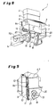
- two V-shaped or two-armed, lower knee lever 16 are attached to which both the connecting rods 15 a, 15 b and at a distance from these upper toggle lever 17 are articulated (see. Fig. 8 ).
- the upper knee lever 17 of the toggle lever pair 16, 17 are further articulated to arranged in the forming table 7 axle, on which outside, diametrically to the Kniehebelanschitch simultaneously rollers 19 are mounted.
- These engage in fixed, in the independent of the movements of the pivoting parts crank plates 20 slide guides 21 a.
- the stationary, non-pivoting link plates 20 control via their slotted guides 21 due to their shape with a vertically upwardly directed portion and a thereto in the direction of passage of the film web 2 (see. Fig. 3 ) substantially horizontally with a slight downward slope portion on the one hand, the lifting movement of the forming table 7 and on the other hand, the pivotal movement of the unit of swing frame 9 with the guided therein, the upper tool 6-carrying forming table. 7
- the Fig. 1 to 4 show the closed position, ie the forming table 7 has moved the lower tool 6 in the upper position against the lower tool 5. In this closed end position, the finished articles are formed and punched out of the film web 2. Subsequently, as in the Fig. 5 to 7 shown - the forming table 7 is lowered in the guide frame 9 and then in the end position (see. Fig. 7 ) for destacking the punched out, lying in the lower tool 6 finished article, with a suitable ejector system, the finished article be transferred from the lower tool 6 in the stacking device 3. In the two end positions of the servomotor 14 stops, so that on the one hand given time for the transformation of plastic articles and thus on the other hand, the ejector has time to transfer the plastic articles from the lower tool in the stacker.
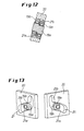
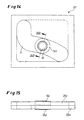
- Fig. 10 to 13 is an arrangement of two pairs in the slide guides 21 of the crank plates 20 guided rollers 19 a, 19 b shown in which the rollers 19 a, 19 b overlapping portion of the axle is designed as Exzenterbolzenendabterrorism 18 a.
- the rollers 19 a, 19 b are thus offset in height to each other, so that the one, in the exemplary embodiment outer roller 19 a specifically targeted only on the lower track 21 a and the other roller 19 b only on the upper track 21 b rolls.
- a tilting of the rollers 19 a, 19 b in the slide guide 21 once up and the other time down is thus excluded.
Landscapes
- Engineering & Computer Science (AREA)
- Mechanical Engineering (AREA)
- Blow-Moulding Or Thermoforming Of Plastics Or The Like (AREA)
- Making Paper Articles (AREA)
- Transmission Devices (AREA)
Abstract
Description
Die Erfindung betrifft eine Vorrichtung zum Herstellen von Hohlkörpern aus thermoplastisch verformbaren Kunststoff-Folien, umfassend einen intermittierenden Folientransport, ein oberhalb der Folienbahn angeordnetes Oberwerkzeug und einen unterhalb der Folienbahn in einem Schwenkrahmen höhenverschiebbar geführten, mit dem Schwenkrahmen ausschwenkbaren Formtisch zur Aufnahme eines Unterwerkzeugs, insbesondere kombiniertes Form- und Stanzwerkzeug, wobei der Formtisch über einen kurvengesteuerte Kniehebel ausweisenden Schubkurbelantrieb an einen Antrieb angeschlossen ist.The invention relates to a device for producing hollow bodies made of thermoplastically deformable plastic films, comprising an intermittent film transport, an upper tool disposed above the film web and a vertically movable below the film web in a swing frame out, swung out with the swing frame molding table for receiving a lower tool, in particular combined Shaping and punching tool, wherein the forming table is connected to a drive via a cam-controlled crank lever drive having a cam-controlled crank lever.
Eine Vorrichtung dieser Art ist aus der
Durch die
Bei den bekannten Vorrichtungen haben sich die Kurvenscheiben als nachteilig gezeigt, da eine Änderung der Bewegungsabläufe einen aufwändigen Austausch der zudem teuren Kurvenscheiben erforderlich macht. Außerdem sind sie wegen der zahlreichen Hebel-Anlenkpunkte störungsanfällig und machen eine große Bauhöhe notwendig, insbesondere bei einer Hebelabstützung des Formtisches von unten, wobei dann auch noch hinzukommt, dass die Hebel und deren Gelenklager die großen Kräfte beim Schließen der Tische zur Umformung und anschließendem Ausstanzen der Fertigartikel aufnehmen müssen.In the known devices, the cams have been found to be disadvantageous, since a change in the movements makes a costly replacement of the more expensive cams required. In addition, they are prone to failure because of the numerous lever articulation points and make a large height necessary, especially with a lever support of the form table from below, in which case also added that the levers and their joint bearings the great forces when closing the tables for forming and subsequent punching must take the finished article.
Der Erfindung liegt daher die Aufgabe zugrunde, eine gattungsgemäße Vorrichtung ohne die genannten Nachteile zu schaffen, die insbesondere einen variablen Betrieb sowie eine ergonomische Bauweise einer Thermoformmaschine ermöglicht.The invention is therefore an object of the invention to provide a generic device without the disadvantages mentioned, in particular a variable Operation and an ergonomic design of a thermoforming machine allows.
Diese Aufgabe wird erfindungsgemäß dadurch gelöst, dass eine Pleuelstange des Schubkurbelantriebs an einer mit dem Drehpunkt des Schwenkrahmens identischen Schwenkwelle angreift, auf der ein unterer Kniehebel befestigt ist, der außerdem gelenkig mit einem oberen, an seinem von dem unteren Kniehebel entfernten, freien Ende am Formtisch angreifenden Kniehebel verbunden ist, dem auf beiden Seiten eines am Formtisch vorgesehenen Achsbolzens jeweils mindestens eine Laufrolle zugeordnet ist, die in ortsfeste, vom Schwenkrahmen und vom Formtisch unabhängige, die lineare Hubbewegung und die Schwenkbewegung des Schwenkrahmens samt Formtisch steuernden Kulissen eingreifen. Indem erfindungsgemäß der untere Kniehebel am Ort des Geschehens zur Schwenkung des gesamten, mit dem Werkzeug einheitlichen Formtisches gelagert ist, nämlich auf der den Drehpunkt des Schwenkrahmens definierenden Schwenkwelle, und somit sowohl der obere Kniehebel als auch die Pleuelstange ihre Lagerung im unteren Kniehebel haben, lässt sich auch beim Einsatz eines aus zwei Hebeln bestehenden Kniehebels eine niedrig bauende Maschine mit ergonomischer, angenehmer Arbeitshöhe erreichen. Dies wird dadurch weiter begünstigt, dass kein einen schwenkenden Tisch tragender, vertikal bewegbarer Untertisch erforderlich ist.This object is achieved in that a connecting rod of the slider crank drive at an identical with the pivot point of the pivot frame pivot shaft is mounted on a lower toggle lever, which also articulated with an upper, at its remote from the lower toggle lever, free end on the forming table engaging toggle lever is connected, which is assigned on both sides of an axis provided on the forming axis journal at least one roller, which engage in fixed, independent of the swing frame and the forming table, the linear lifting movement and the pivotal movement of the swing frame together with forming table controlling scenes. In accordance with the invention, the lower toggle lever is mounted at the location of the action for pivoting the entire forming table which is uniform with the tool, namely on the pivot shaft defining the pivot point of the pivot frame, and thus both the upper toggle lever and the connecting rod have their bearing in the lower toggle lever Even when using a two-lever toggle lever to achieve a low-build machine with ergonomic, comfortable working height. This is further facilitated by the fact that no vertically moveable undertable carrying a pivoting table is required.
Für die Hub- und Schwenkbewegung sind keine gesonderten Kurvenscheiben und mehreren Hebelanordnungen erforderlich vielmehr, wird über die in die ortsfesten Kulissen eingreifenden Laufrollen dasselbe Kniehebelpaar sowohl für die eine als auch für die andere Bewegungsrichtung wirksam, wobei lediglich ein Antrieb erforderlich ist, vorzugsweise ein Servomotor. Dessen Drehzahl kann während eines Schwenkhubes in einfacher Weise verändert werden, so dass ein gewünschter Bewegungsablauf der Kippbewegung einschließlich eines sanften Anfahrens der Endlagen erreichbar ist. Da die Hub- und Schwenkbewegung zudem mechanisch synchronisiert sind, besteht keine Kollisionsgefahr, d. h. es kann zu keinen Überschneidungen der Bewegungsabläufe kommen.For the lifting and pivoting movement no separate cams and several lever arrangements are required rather, the same toggle lever pair is effective for both the one and the other direction of movement, which only one drive is required, preferably a servomotor on the engaging in the stationary scenes wheels. Whose speed can be changed during a swivel stroke in a simple manner, so that a desired movement of the tilting movement including a soft start of the end positions can be achieved. Since the lifting and pivoting movement also mechanical are synchronized, there is no risk of collision, ie there can be no overlap of the movements.
Die kompakte, niedrige Bauweise der Thermoformmaschine, bei der der Angriffspunkt der Pleuelstange an dem unteren Kniehebel beabstandet von dem Gelenk der beiden Kniehebel vorgesehen ist, wobei der untere Kniehebel vorteilhaft einstückig in einer V-Form bzw. zweiarmig für die beiden individuellen Anlenkpunkte ausgebildet ist, ermöglicht einen Betrieb mit einem sehr kleinen Schwenkwinkel. Denn schon bei einem Schwenkwinkel von lediglich etwa 30 ° nimmt der über den Schwenkrahmen gemeinsam mit dem Formwerkzeug verschwenkte Formtisch eine für das Entstapeln der Fertigartikel in einer zugänglichen Arbeitshöhe liegende Position ein. Das bietet einen besseren Halt beim Stapeln von Bechern und insbesondere bei ansonsten nur mit viel Aufwand in der Horizontalen abzustapelnden Deckeln.The compact, low construction of the thermoforming machine, wherein the point of application of the connecting rod at the lower toggle lever spaced from the joint of the two toggle lever is provided, the lower toggle is advantageously integrally formed in a V-shape or two-armed for the two individual pivot points, allows operation with a very small tilt angle. For even at a pivoting angle of only about 30 °, the molding table, which is swiveled over the pivoting frame together with the forming tool, assumes a position lying at an accessible working height for destacking the finished articles. This provides a better grip when stacking cups and especially in otherwise stash with much effort in the horizontal lids.
Eine bevorzugte Ausführung der Erfindung sieht vor, dass der Schubkurbelantrieb zwei parallel voneinander beabstandete Pleuelstangen aufweist, die mit ihnen jeweils zugeordneten Kniehebeln mit dem kulissengesteuerten Formtisch verbunden sind. Durch den auf die Schwenkwelle wirkenden Doppel-Schubkurbelantrieb werden die Aufbringung der hohen Schließkräfte und die Hubbewegungen des in dem Schwenkrahmen geführten Formtisches begünstigt.A preferred embodiment of the invention provides that the sliding crank drive has two parallel spaced connecting rods, which are connected to them respectively associated toggle levers with the backdrop-controlled forming table. By acting on the pivot shaft double-crank drive the application of high closing forces and the strokes of the guided in the swing frame molding table are favored.
Es wird ausgestaltungsgemäß vorgeschlagen, dass gleichzeitig der obere Kniehebel mit seinem freien Ende auf dem oder den die Laufrollen tragenden Achsbolzen gelagert ist. Dies kann somit ein quer durch den Formtisch hindurch geführter einstückiger Achsbolzen sein oder es können vorteilhaft zwei Achsbolzen vorgesehen werden. Alternativ ist es möglich, für die Laufrollen und die Anlenkpunkte der oberen Kniehebel separate Lagerstummel- bzw. zapfen am Formtisch auszubilden.It is proposed according to the design that at the same time the upper toggle lever is mounted with its free end on or the axle rollers carrying the rollers. This can thus be a one-piece axle pin guided transversely through the forming table or, advantageously, two axle bolts can be provided. Alternatively, it is possible for the rollers and the pivot points of the upper toggle lever separate Lagerstummel- or tap form the forming table.
Ein Vorschlag der Erfindung sieht vor, dass der Formtisch beidseitig angeordnete Linearführungen aufweist, deren bewegliche Teile am Formtisch und deren Führungsschienen am Schwenkrahmen vorgesehen sind. Mit den Linearführungen, beispielsweise Rollenumlaufführungen, lassen sich Kippmomente um die horizontale Querachse auffangen.A proposal of the invention provides that the forming table has arranged on both sides linear guides whose moving parts are provided on the forming table and the guide rails on the swing frame. With the linear guides, for example roller recirculation guides, tilting moments can be absorbed around the horizontal transverse axis.
Nach einer vorteilhaften Ausführung der Erfindung sind die den oder - beim Doppel-Kurbelantrieb - die beiden oberen Kniehebel am Formtisch lagernden Achsbolzen exzentrisch ausgebildet, wobei auf dem einen Exzenterabschnitt eine auf der unteren Laufbahn der Kulisse und einem anderen Exzenterabschnitt eine auf der oberen Laufbahn der Kulisse abrollende Laufrolle angeordnet ist.According to an advantageous embodiment of the invention, the or the double crank mechanism - the two upper knee lever on the forming table overlapping axle are formed eccentrically, on one eccentric one on the lower track of the gate and another eccentric on the upper track of the gate rolling roller is arranged.
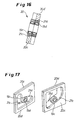
Nach einer vorteilhaften alternativen Bauweise sind die den oder beiden oberen Kniehebel am Formtisch lagernden Achsbolzen zylindrisch und tragen koaxial nebeneinander zwei Laufrollen, die auf zueinander höhenversetzten, benachbarten Laufbahnen, die nach einer Ausgestaltung der Erfindung in jeweils einer separaten Kulissenscheibe ausgebildet sein können, der Kulisse abrollen.According to an advantageous alternative construction, the two or the upper toggle lever on the forming table overlapping axle are cylindrical and coaxial side by side two rollers that roll on mutually staggered, adjacent raceways, which may be formed according to an embodiment of the invention in each case a separate crank disc, roll the scenery ,
In beiden Fällen lässt sich erreichen, dass die Drehrichtung der Laufrollen auf dem Weg durch die Kulisse eindeutig bestimmt ist und sich durch eine undefinierte Anlage der Laufrollen einmal oben und einmal unten in der Kulisse nicht umkehren kann, was zu erheblich schnellerem Verschleiß führen würde.In both cases, it can be achieved that the direction of rotation of the rollers is clearly determined on the way through the backdrop and can not reverse through an undefined system of rollers once up and down once in the scenery, which would lead to significantly faster wear.
Weitere Einzelheiten und Merkmale der Erfindung ergeben sich aus den Ansprüchen und der nachfolgenden Beschreibung von in den Zeichnungen dargestellten Ausführungsbeispielen der Erfindung. Es zeigen:
- Fig. 1
- in einer perspektivischen Gesamtansicht die Formstation, einer Thermoformmaschine, d. h. ohne deren als solche hinlänglich be- kannten peripheren Anlagenteile wie Auf- und Abwickelrollen für die Kunststoff-Folie, Folien-Transporteinrichtung und Heizeinrichtung;
- Fig. 2
- die Formstation nach
Fig. 1 in der Vorderansicht von der Entnahme- seite her gesehen mit dort zum Abstapeln der Fertigprodukte ange- ordneter Fang- bzw. Stapelplatte; - Fig. 3
- die Formstation nach
Fig. 1 in der Seitenansicht; - Fig. 4
- die Formstation nach
Fig. 1 in der Draufsicht; - Fig. 5
- die Formstation nach
Fig. 1 in der Seitenansicht mit geöffnetem Werkzeug, d. h. abgesenktem Formtisch; - Fig. 6
- eine Seitenansicht wie zuvor in
Fig. 5 , demgegenüber in einer Zwischenposition beim Verschwenken zum Entstapeln der Fertigarti- kel; - Fig. 7
- eine Ansicht wie zuvor in
Fig. 6 , demgegenüber ausgeschwenkt in die Endposition zum Entstapeln der Fertigartikel; - Fig. 8
- die Formstation nach
Fig. 1 in einer perspektivischen Ansicht von unten gesehen; - Fig. 9
- als Einzelheit der Formstation in einer perspektivischen Ansicht die Linearführung des Formtisches im Schwenkrahmen;
- Fig. 10
- als Einzelheit der Formstation eine ortsfeste Kulisse mit darin geführ- ter Laufrolle des Formtisches;
- Fig. 11
- die Kulisse nach
Fig. 10 in der Draufsicht; - Fig. 12
- als Einzelheit der
Fig. 10 einen Schnitt entlang der Linie XII-XII; - Fig. 13
- perspektivische Darstellung der Kulisse mit den darin geführten Lauf- rollen nach den
Fig. 10 bis 12 ; - Fig. 14
- in der Vorderansicht eine andere Ausführung einer ortsfesten Kulisse mit darin geführten Laufrollen;
- Fig. 15
- die Kulisse nach
Fig. 14 in der Draufsicht; - Fig. 16
- einen Schnitt entlang der Linie XVI-XVI von
Fig. 14 ; und - Fig. 17
- perspektivische Darstellungen der Kulisse mit den darin geführten Laufrollen nach
Fig. 14 .bis 16
- Fig. 1
- in a perspective overall view of the forming station, a thermoforming machine, ie without their sufficient as such knew peripheral plant parts such as winding and unwinding rollers for the plastic film, film transport device and heater;
- Fig. 2
- the forming station after
Fig. 1 in the front view seen from the removal side with catching or stacking plate arranged there for destacking the finished products; - Fig. 3
- the forming station after
Fig. 1 in the side view; - Fig. 4
- the forming station after
Fig. 1 in the plan view; - Fig. 5
- the forming station after
Fig. 1 in the side view with open tool, ie lowered molding table; - Fig. 6
- a side view as before in
Fig. 5 in contrast, in an intermediate position during pivoting for destacking the finished articles; - Fig. 7
- a view as before in
Fig. 6 , in contrast, swung out into the final position for destacking the finished article; - Fig. 8
- the forming station after
Fig. 1 seen in a perspective view from below; - Fig. 9
- as a detail of the forming station in a perspective view of the linear guide of the forming table in the swing frame;
- Fig. 10
- as a detail of the forming station a stationary backdrop with guided roller of the forming table;
- Fig. 11
- the scenery after
Fig. 10 in the plan view; - Fig. 12
- as a detail of
Fig. 10 a section along the line XII-XII; - Fig. 13
- Perspective view of the scenery with the running wheels guided inside
10 to 12 ; - Fig. 14
- in the front view of another embodiment of a fixed backdrop with guided therein rollers;
- Fig. 15
- the scenery after
Fig. 14 in the plan view; - Fig. 16
- a section along the line XVI-XVI of
Fig. 14 ; and - Fig. 17
- perspective views of the backdrop with the guided therein rollers
Fig. 14 to 16 ,
In den
Der Formtisch 7 mit dem Unterwerkzeug 6 wird beidseitig in Linearführungen 8 a, 8 b eines Schwenkrahmens 9 geführt. Die beweglichen Teile 10, z. B. Führungsschuhe, der Linearführungen 8 a, 8 b sind am Formtisch 7 bzw. Unterwerkzeug 6 und deren Führungsschienen 11 sind am Schwenkrahmen 9 angeordnet (vgl.
Auf der Schwenkwelle 12 sind zwei V-förmige bzw. zweiarmige, untere Kniehebel 16 befestigt, an die sowohl die Pleuelstangen 15 a, 15 b als auch im Abstand von diesen obere Kniehebel 17 angelenkt sind (vgl.
Die
In den
Derselbe, äußert wirksame Effekt lässt sich erreichen, wenn auf dem bzw. den Achsbolzen 18 koaxial nebeneinander zwei Laufrollen 19 c, 19 d gelagert sind, wie in den
- 11
- Formstationforming station
- 22
- Folienbahnsheet
- 33
- Fang-/StapelplatteArrester / pallet
- 44
- Querhauptcrosshead
- 55
- Oberwerkzeugupper tool
- 66
- Unterwerkzeuglower tool
- 77
- Formtischmold table
- 8 a, 8 b8 a, 8 b
- Linearführunglinear guide
- 99
- Schwenkrahmenswing frame
- 1010
- Bewegliches Teil der LinearführungMoving part of the linear guide
- 1111
- Führungsschiene der LinearführungGuide rail of the linear guide
- 1212
- Schwenkwellepivot shaft
- 1313
- SchubkurbelantriebCrank drive
- 1414
- Servomotor bzw. Servo-Getriebemotor / AntriebServomotor or servo geared motor / drive
- 15 a, 15 b15 a, 15 b
- Pleuelstangeconnecting rod
- 1616
- Unterer KniehebelLower toggle
- 1717
- Oberer KniehebelUpper toggle
- 1818
- Achsbolzenaxle
- 18 a18 a
- Exzenterabschnitteccentric
- 1919
- Laufrollecaster
- 19 a, 19 b19 a, 19 b
- Laufrolle auf ExzenterabschnittRoller on eccentric section
- 19 c, 19 d19 c, 19 d
- koaxial angeordnete LaufrollenCoaxially arranged rollers
- 20; 20 c, 20 d20; 20 c, 20 d
- Kulissenscheibenlink discs
- 2121
- Kulissenführunglink guide
- 21 a21 a
- Untere Laufbahn der KulissenführungLower raceway of the slotted guide
- 21 b21 b
- Obere Laufbahn der KulissenführungUpper raceway of the slotted guide
- 21 c, 21 d21 c, 21 d
- Höhenversetzte Laufbahnen der KulissenführungHeight-offset raceways of the slotted guide
Claims (8)
- A device for manufacturing hollow bodies of thermoplastically deformable plastic films, comprising an intermittent film transport, an upper die (5) that is arranged above the film strip (2) and a moulding table (7) for accommodating a lower die (6), wherein said moulding table is guided in a vertically displaceable fashion underneath the film strip in a pivoting frame (9) and can be pivoted together with the pivoting frame (9), particularly a combined moulding and punching tool, wherein the moulding table (7) is connected to a drive (14) by means of a slider-crank mechanism (13) that features cam-controlled toggle levers,
characterized in
that a connecting rod (15a, 15b) of the slider-crank mechanism (13) engages on a pivoting shaft (12) that is identical to the center of motion of the pivoting frame (9) and on which a lower toggle lever (16) is mounted that is also connected in an articulated fashion to an upper toggle lever (17) that engages on the moulding table (7) with its free end that is situated distant from the lower toggle lever (16), wherein at least one roller (19; 19a, 19b; 19c, 19d) is assigned to the upper toggle lever on both sides of an axle bolt (18; 18a) provided on the moulding table (7), and wherein said rollers engage into stationary links (20, 21; 20c, 20d, 21a, 21b, 21c, 21d) that are realized independently of the pivoting frame (9) and the moulding table (7) and control the linear lifting motion and the pivoting motion of the pivoting frame (9) including the moulding table (7). - The device according to Claim 1,
characterized in
that the upper toggle lever (17) is simultaneously supported on the axle bolt (18; 18a) that carries the roller or the rollers (19; 19a, 19b; 19c, 19d) with its free end. - The device according to Claim 1 or 2,
characterized in
that the slider-crank mechanism (13) features two parallel connecting rods (15a, 15b) that are spaced apart from one another and connected to the link-controlled moulding table (7) with their respectively assigned toggle levers (16, 17). - The device according to one of Claims 1 to 3,
characterized by
a servo motor (14) that drives the connecting rods (15a, 15b). - The device according to one of Claims 1 to 4,
characterized in
that the moulding table (7) features linear guides (8a, 8b) that are arranged on both sides, wherein the movable parts (10) of the linear guides are provided on the moulding table (7) and their guide rails (11) are provided on the pivoting frame (9). - The device according to one of Claims 1 to 5,
characterized in
that the axle bolts (18a) that support the or both upper toggle lever(s) (17) on the moulding table (7) are realized eccentrically, and in that a roller (19a, 19b) that rolls on the lower slideway (21a) of the link (20, 21) is arranged on one eccentric section and a roller that rolls on the upper slideway (21b) of the link (20, 21) is arranged on another eccentric section. - The device according to one of Claims 1 to 5,
characterized in
that the axle bolts (18) that support the or both upper toggle lever(s) (17) on the moulding table (7) are realized cylindrically and carry two rollers (19c, 19d) coaxially adjacent to one another, wherein said rollers roll on adjacent slideways (21c, 21d) of the link (20, 21; 21a, 21b) that are vertically offset relative to one another. - The device according to Claim 7,
characterized in
that each slideway (21c, 21d) is realized in a separate link plate (20c, 20d).
Applications Claiming Priority (1)
| Application Number | Priority Date | Filing Date | Title |
|---|---|---|---|
| DE102008032806A DE102008032806A1 (en) | 2008-07-11 | 2008-07-11 | Apparatus for producing hollow bodies from thermoplastically deformable plastic films |
Publications (2)
| Publication Number | Publication Date |
|---|---|
| EP2143550A1 EP2143550A1 (en) | 2010-01-13 |
| EP2143550B1 true EP2143550B1 (en) | 2011-01-26 |
Family
ID=41228679
Family Applications (1)
| Application Number | Title | Priority Date | Filing Date |
|---|---|---|---|
| EP09006372A Active EP2143550B1 (en) | 2008-07-11 | 2009-05-12 | Device for manufacturing hollow bodies from thermoplastic reformable plastic films |
Country Status (4)
| Country | Link |
|---|---|
| US (1) | US8105069B2 (en) |
| EP (1) | EP2143550B1 (en) |
| AT (1) | ATE496755T1 (en) |
| DE (2) | DE102008032806A1 (en) |
Cited By (2)
| Publication number | Priority date | Publication date | Assignee | Title |
|---|---|---|---|---|
| EP2840294A1 (en) | 2013-08-21 | 2015-02-25 | Gabler Thermoform GmbH & Co. KG | Central lubrication distributor system of a thermoforming machine |
| DE102017009915B4 (en) * | 2017-10-20 | 2020-02-20 | Illig Maschinenbau Gmbh & Co. Kg | Drive system for a combined forming and punching station of a thermoforming machine |
Families Citing this family (6)
| Publication number | Priority date | Publication date | Assignee | Title |
|---|---|---|---|---|
| EP2110220A3 (en) * | 2008-04-14 | 2010-08-04 | Fill Gesellschaft m.b.H. | Device for manufacturing moulded parts, in particular of moulded foam parts |
| US10431567B2 (en) * | 2010-11-03 | 2019-10-01 | Cree, Inc. | White ceramic LED package |
| US9493300B2 (en) * | 2011-10-04 | 2016-11-15 | The Gsi Group Llc | External impactor for bulk storage containers |
| KR200481141Y1 (en) * | 2016-01-11 | 2016-08-18 | 김병노 | Plastic cup thermo air pressure forming machine |
| EP3095583B1 (en) * | 2016-04-15 | 2018-02-07 | Güven Teknik Makina ve Kalip San. Dis Tic. Ltd. Sti. | Machine and method for producing thermoformed articles having an improved stacking system |
| DE102019000964B4 (en) * | 2019-02-09 | 2021-12-09 | Illig Maschinenbau Gmbh & Co. Kg | Drive system for a combined forming and punching station of a thermoforming machine |
Family Cites Families (6)
| Publication number | Priority date | Publication date | Assignee | Title |
|---|---|---|---|---|
| DE19710475A1 (en) | 1997-03-13 | 1998-09-17 | Kuhne Anlagenbau Gmbh | Device for the production of hollow bodies from thermoplastic plastic films |
| US6135756A (en) * | 1997-06-13 | 2000-10-24 | Arends; Albert W. | Differential pressure forming, trimming and stacking apparatus |
| DE19921668C1 (en) * | 1999-05-11 | 2001-01-04 | Illig Maschinenbau Adolf | Method for moving a swivel table in a device for forming and punching out containers from a thermoplastic film and device for carrying out the method |
| DE10100119C1 (en) * | 2001-01-03 | 2002-06-20 | Illig Maschinenbau Adolf | Apparatus for molding and punching out containers from a thermoplastic sheet, comprises a molding table on which one mold half is mounted, which swivels in a guideway between its pivot and sheet |
| DE10157134B4 (en) | 2001-11-21 | 2005-07-07 | Adolf Illig Maschinenbau Gmbh & Co.Kg | Apparatus for forming and punching containers from a sheet of thermoplastic material |
| ATE517731T1 (en) * | 2002-04-25 | 2011-08-15 | Kuhne Anlagenbau Gmbh | THERMOFORMING SYSTEM FOR PRODUCING MOLDED BODIES FROM PLASTIC FILM, AND METHOD FOR THE PRODUCTION THEREOF |
-
2008
- 2008-07-11 DE DE102008032806A patent/DE102008032806A1/en not_active Withdrawn
-
2009
- 2009-05-12 AT AT09006372T patent/ATE496755T1/en active
- 2009-05-12 DE DE502009000345T patent/DE502009000345D1/en active Active
- 2009-05-12 EP EP09006372A patent/EP2143550B1/en active Active
- 2009-07-06 US US12/497,860 patent/US8105069B2/en not_active Expired - Fee Related
Cited By (2)
| Publication number | Priority date | Publication date | Assignee | Title |
|---|---|---|---|---|
| EP2840294A1 (en) | 2013-08-21 | 2015-02-25 | Gabler Thermoform GmbH & Co. KG | Central lubrication distributor system of a thermoforming machine |
| DE102017009915B4 (en) * | 2017-10-20 | 2020-02-20 | Illig Maschinenbau Gmbh & Co. Kg | Drive system for a combined forming and punching station of a thermoforming machine |
Also Published As
| Publication number | Publication date |
|---|---|
| DE102008032806A1 (en) | 2010-01-14 |
| US8105069B2 (en) | 2012-01-31 |
| ATE496755T1 (en) | 2011-02-15 |
| DE502009000345D1 (en) | 2011-03-10 |
| EP2143550A1 (en) | 2010-01-13 |
| US20100009023A1 (en) | 2010-01-14 |
Similar Documents
| Publication | Publication Date | Title |
|---|---|---|
| EP2143550B1 (en) | Device for manufacturing hollow bodies from thermoplastic reformable plastic films | |
| DE68903016T2 (en) | Device for closing containers by means of a sealable film. | |
| DE2100426C3 (en) | Conveyor device for the continuous transport of preformed collapsible containers with rectangular bottoms through the filling and closing stations of a packaging machine | |
| CH700204A2 (en) | Separating- and stripping device for cable processing machine, has two eccentric cams arranged with two piston rods for simultaneous lifting and lowering of two knife blocks at crankshaft | |
| EP2616196A1 (en) | Method for transferring a metal coil | |
| EP2412637B1 (en) | Packaging machine with multiple work stations | |
| DE4211219C2 (en) | Arrangement for handling flat material | |
| EP1052080B1 (en) | Method for moving a tilting table in a apparatus for forming and punching out containers made of a thermoplastic foil and apparatus for carrying out the method | |
| DE2528509A1 (en) | METHOD AND DEVICE FOR AUTOMATIC STORAGE OF PARTS MADE OF ELASTOMERAL MATERIAL | |
| DE1696023C3 (en) | Feeding device of a glass ware forming machine | |
| DE4005948A1 (en) | BOOKBINDING MACHINE FOR ROUNDING BOOK BLOCKS | |
| DE1602607A1 (en) | Conveyor device | |
| DE2155114C2 (en) | Transport device for guiding a number of identical carriages in a circuit | |
| DE3103149A1 (en) | Automatic machine for the continuous packaging of products | |
| DE102007054729A1 (en) | Device for handling vessels comprises an adjusting part formed as a vertical/horizontal adjusting unit with two translational degrees of freedom and lifting units aligned in a V-shape to each other | |
| WO1995022498A1 (en) | Device for releasing a product from a continuously circulating belt | |
| DE2935263A1 (en) | Automatic book-stacking machine - holds books between rotary punches on top and bottom conveyors | |
| EP0241680B1 (en) | Method and apparatus for closing containers | |
| DE19706182C2 (en) | Blow molding machine | |
| DE4022110C2 (en) | Device for pushing several glass objects from one conveyor belt to another | |
| EP1601514B1 (en) | Actuating system for an externally actuated part of a clamping unit | |
| DE2601738C2 (en) | Method and apparatus for sharing a stream of cigarettes or the like. | |
| DE10309974B4 (en) | Guide system for an externally actuated part of a closing unit | |
| EP3318398A1 (en) | Device for manufacturing containers | |
| DE2921157C2 (en) | Device for the deformation of foamed sheets or the like. Made of plastics |
Legal Events
| Date | Code | Title | Description |
|---|---|---|---|
| PUAI | Public reference made under article 153(3) epc to a published international application that has entered the european phase |
Free format text: ORIGINAL CODE: 0009012 |
|
| AK | Designated contracting states |
Kind code of ref document: A1 Designated state(s): AT BE BG CH CY CZ DE DK EE ES FI FR GB GR HR HU IE IS IT LI LT LU LV MC MK MT NL NO PL PT RO SE SI SK TR |
|
| 17P | Request for examination filed |
Effective date: 20100601 |
|
| GRAP | Despatch of communication of intention to grant a patent |
Free format text: ORIGINAL CODE: EPIDOSNIGR1 |
|
| GRAS | Grant fee paid |
Free format text: ORIGINAL CODE: EPIDOSNIGR3 |
|
| GRAA | (expected) grant |
Free format text: ORIGINAL CODE: 0009210 |
|
| AK | Designated contracting states |
Kind code of ref document: B1 Designated state(s): AT BE BG CH CY CZ DE DK EE ES FI FR GB GR HR HU IE IS IT LI LT LU LV MC MK MT NL NO PL PT RO SE SI SK TR |
|
| REG | Reference to a national code |
Ref country code: GB Ref legal event code: FG4D Free format text: NOT ENGLISH |
|
| REG | Reference to a national code |
Ref country code: CH Ref legal event code: EP |
|
| REG | Reference to a national code |
Ref country code: CH Ref legal event code: NV Representative=s name: SCHMAUDER & PARTNER AG PATENT- UND MARKENANWAELTE |
|
| REG | Reference to a national code |
Ref country code: IE Ref legal event code: FG4D Free format text: LANGUAGE OF EP DOCUMENT: GERMAN |
|
| REF | Corresponds to: |
Ref document number: 502009000345 Country of ref document: DE Date of ref document: 20110310 Kind code of ref document: P |
|
| REG | Reference to a national code |
Ref country code: DE Ref legal event code: R096 Ref document number: 502009000345 Country of ref document: DE Effective date: 20110310 |
|
| REG | Reference to a national code |
Ref country code: NL Ref legal event code: VDEP Effective date: 20110126 |
|
| LTIE | Lt: invalidation of european patent or patent extension |
Effective date: 20110126 |
|
| PG25 | Lapsed in a contracting state [announced via postgrant information from national office to epo] |
Ref country code: LV Free format text: LAPSE BECAUSE OF FAILURE TO SUBMIT A TRANSLATION OF THE DESCRIPTION OR TO PAY THE FEE WITHIN THE PRESCRIBED TIME-LIMIT Effective date: 20110126 Ref country code: GR Free format text: LAPSE BECAUSE OF FAILURE TO SUBMIT A TRANSLATION OF THE DESCRIPTION OR TO PAY THE FEE WITHIN THE PRESCRIBED TIME-LIMIT Effective date: 20110427 Ref country code: ES Free format text: LAPSE BECAUSE OF FAILURE TO SUBMIT A TRANSLATION OF THE DESCRIPTION OR TO PAY THE FEE WITHIN THE PRESCRIBED TIME-LIMIT Effective date: 20110507 Ref country code: NO Free format text: LAPSE BECAUSE OF FAILURE TO SUBMIT A TRANSLATION OF THE DESCRIPTION OR TO PAY THE FEE WITHIN THE PRESCRIBED TIME-LIMIT Effective date: 20110426 Ref country code: LT Free format text: LAPSE BECAUSE OF FAILURE TO SUBMIT A TRANSLATION OF THE DESCRIPTION OR TO PAY THE FEE WITHIN THE PRESCRIBED TIME-LIMIT Effective date: 20110126 Ref country code: PT Free format text: LAPSE BECAUSE OF FAILURE TO SUBMIT A TRANSLATION OF THE DESCRIPTION OR TO PAY THE FEE WITHIN THE PRESCRIBED TIME-LIMIT Effective date: 20110526 Ref country code: SE Free format text: LAPSE BECAUSE OF FAILURE TO SUBMIT A TRANSLATION OF THE DESCRIPTION OR TO PAY THE FEE WITHIN THE PRESCRIBED TIME-LIMIT Effective date: 20110126 Ref country code: HR Free format text: LAPSE BECAUSE OF FAILURE TO SUBMIT A TRANSLATION OF THE DESCRIPTION OR TO PAY THE FEE WITHIN THE PRESCRIBED TIME-LIMIT Effective date: 20110126 |
|
| REG | Reference to a national code |
Ref country code: IE Ref legal event code: FD4D |
|
| PG25 | Lapsed in a contracting state [announced via postgrant information from national office to epo] |
Ref country code: CY Free format text: LAPSE BECAUSE OF FAILURE TO SUBMIT A TRANSLATION OF THE DESCRIPTION OR TO PAY THE FEE WITHIN THE PRESCRIBED TIME-LIMIT Effective date: 20110126 Ref country code: NL Free format text: LAPSE BECAUSE OF FAILURE TO SUBMIT A TRANSLATION OF THE DESCRIPTION OR TO PAY THE FEE WITHIN THE PRESCRIBED TIME-LIMIT Effective date: 20110126 Ref country code: FI Free format text: LAPSE BECAUSE OF FAILURE TO SUBMIT A TRANSLATION OF THE DESCRIPTION OR TO PAY THE FEE WITHIN THE PRESCRIBED TIME-LIMIT Effective date: 20110126 Ref country code: SI Free format text: LAPSE BECAUSE OF FAILURE TO SUBMIT A TRANSLATION OF THE DESCRIPTION OR TO PAY THE FEE WITHIN THE PRESCRIBED TIME-LIMIT Effective date: 20110126 Ref country code: BG Free format text: LAPSE BECAUSE OF FAILURE TO SUBMIT A TRANSLATION OF THE DESCRIPTION OR TO PAY THE FEE WITHIN THE PRESCRIBED TIME-LIMIT Effective date: 20110426 Ref country code: PL Free format text: LAPSE BECAUSE OF FAILURE TO SUBMIT A TRANSLATION OF THE DESCRIPTION OR TO PAY THE FEE WITHIN THE PRESCRIBED TIME-LIMIT Effective date: 20110126 |
|
| PG25 | Lapsed in a contracting state [announced via postgrant information from national office to epo] |
Ref country code: DK Free format text: LAPSE BECAUSE OF FAILURE TO SUBMIT A TRANSLATION OF THE DESCRIPTION OR TO PAY THE FEE WITHIN THE PRESCRIBED TIME-LIMIT Effective date: 20110126 Ref country code: EE Free format text: LAPSE BECAUSE OF FAILURE TO SUBMIT A TRANSLATION OF THE DESCRIPTION OR TO PAY THE FEE WITHIN THE PRESCRIBED TIME-LIMIT Effective date: 20110126 Ref country code: IE Free format text: LAPSE BECAUSE OF FAILURE TO SUBMIT A TRANSLATION OF THE DESCRIPTION OR TO PAY THE FEE WITHIN THE PRESCRIBED TIME-LIMIT Effective date: 20110126 |
|
| BERE | Be: lapsed |
Owner name: GABLER THERMOFORM G.M.B.H. & CO. KG Effective date: 20110531 |
|
| PG25 | Lapsed in a contracting state [announced via postgrant information from national office to epo] |
Ref country code: SK Free format text: LAPSE BECAUSE OF FAILURE TO SUBMIT A TRANSLATION OF THE DESCRIPTION OR TO PAY THE FEE WITHIN THE PRESCRIBED TIME-LIMIT Effective date: 20110126 Ref country code: RO Free format text: LAPSE BECAUSE OF FAILURE TO SUBMIT A TRANSLATION OF THE DESCRIPTION OR TO PAY THE FEE WITHIN THE PRESCRIBED TIME-LIMIT Effective date: 20110126 Ref country code: CZ Free format text: LAPSE BECAUSE OF FAILURE TO SUBMIT A TRANSLATION OF THE DESCRIPTION OR TO PAY THE FEE WITHIN THE PRESCRIBED TIME-LIMIT Effective date: 20110126 |
|
| PLBE | No opposition filed within time limit |
Free format text: ORIGINAL CODE: 0009261 |
|
| STAA | Information on the status of an ep patent application or granted ep patent |
Free format text: STATUS: NO OPPOSITION FILED WITHIN TIME LIMIT |
|
| PG25 | Lapsed in a contracting state [announced via postgrant information from national office to epo] |
Ref country code: MC Free format text: LAPSE BECAUSE OF NON-PAYMENT OF DUE FEES Effective date: 20110531 Ref country code: MT Free format text: LAPSE BECAUSE OF FAILURE TO SUBMIT A TRANSLATION OF THE DESCRIPTION OR TO PAY THE FEE WITHIN THE PRESCRIBED TIME-LIMIT Effective date: 20110126 |
|
| 26N | No opposition filed |
Effective date: 20111027 |
|
| REG | Reference to a national code |
Ref country code: FR Ref legal event code: ST Effective date: 20120131 |
|
| REG | Reference to a national code |
Ref country code: DE Ref legal event code: R097 Ref document number: 502009000345 Country of ref document: DE Effective date: 20111027 |
|
| PG25 | Lapsed in a contracting state [announced via postgrant information from national office to epo] |
Ref country code: BE Free format text: LAPSE BECAUSE OF NON-PAYMENT OF DUE FEES Effective date: 20110531 |
|
| PG25 | Lapsed in a contracting state [announced via postgrant information from national office to epo] |
Ref country code: FR Free format text: LAPSE BECAUSE OF NON-PAYMENT OF DUE FEES Effective date: 20110531 |
|
| PG25 | Lapsed in a contracting state [announced via postgrant information from national office to epo] |
Ref country code: MK Free format text: LAPSE BECAUSE OF FAILURE TO SUBMIT A TRANSLATION OF THE DESCRIPTION OR TO PAY THE FEE WITHIN THE PRESCRIBED TIME-LIMIT Effective date: 20110126 |
|
| PG25 | Lapsed in a contracting state [announced via postgrant information from national office to epo] |
Ref country code: LU Free format text: LAPSE BECAUSE OF NON-PAYMENT OF DUE FEES Effective date: 20110512 |
|
| PG25 | Lapsed in a contracting state [announced via postgrant information from national office to epo] |
Ref country code: IS Free format text: LAPSE BECAUSE OF FAILURE TO SUBMIT A TRANSLATION OF THE DESCRIPTION OR TO PAY THE FEE WITHIN THE PRESCRIBED TIME-LIMIT Effective date: 20110126 |
|
| PG25 | Lapsed in a contracting state [announced via postgrant information from national office to epo] |
Ref country code: TR Free format text: LAPSE BECAUSE OF FAILURE TO SUBMIT A TRANSLATION OF THE DESCRIPTION OR TO PAY THE FEE WITHIN THE PRESCRIBED TIME-LIMIT Effective date: 20110126 |
|
| PG25 | Lapsed in a contracting state [announced via postgrant information from national office to epo] |
Ref country code: HU Free format text: LAPSE BECAUSE OF FAILURE TO SUBMIT A TRANSLATION OF THE DESCRIPTION OR TO PAY THE FEE WITHIN THE PRESCRIBED TIME-LIMIT Effective date: 20110126 |
|
| GBPC | Gb: european patent ceased through non-payment of renewal fee |
Effective date: 20130512 |
|
| PG25 | Lapsed in a contracting state [announced via postgrant information from national office to epo] |
Ref country code: GB Free format text: LAPSE BECAUSE OF NON-PAYMENT OF DUE FEES Effective date: 20130512 |
|
| REG | Reference to a national code |
Ref country code: AT Ref legal event code: MM01 Ref document number: 496755 Country of ref document: AT Kind code of ref document: T Effective date: 20140512 |
|
| PG25 | Lapsed in a contracting state [announced via postgrant information from national office to epo] |
Ref country code: AT Free format text: LAPSE BECAUSE OF NON-PAYMENT OF DUE FEES Effective date: 20140512 |
|
| P01 | Opt-out of the competence of the unified patent court (upc) registered |
Effective date: 20230517 |
|
| PGFP | Annual fee paid to national office [announced via postgrant information from national office to epo] |
Ref country code: DE Payment date: 20230929 Year of fee payment: 15 |
|
| PGFP | Annual fee paid to national office [announced via postgrant information from national office to epo] |
Ref country code: IT Payment date: 20230929 Year of fee payment: 15 Ref country code: CH Payment date: 20231009 Year of fee payment: 15 |