EP2143458B1 - Can fixture - Google Patents
Can fixture Download PDFInfo
- Publication number
- EP2143458B1 EP2143458B1 EP09172349.4A EP09172349A EP2143458B1 EP 2143458 B1 EP2143458 B1 EP 2143458B1 EP 09172349 A EP09172349 A EP 09172349A EP 2143458 B1 EP2143458 B1 EP 2143458B1
- Authority
- EP
- European Patent Office
- Prior art keywords
- source
- dispenser
- locator
- membrane
- spout
- Prior art date
- Legal status (The legal status is an assumption and is not a legal conclusion. Google has not performed a legal analysis and makes no representation as to the accuracy of the status listed.)
- Expired - Lifetime
Links
- 239000000853 adhesive Substances 0.000 claims description 28
- 230000001070 adhesive effect Effects 0.000 claims description 24
- 239000012528 membrane Substances 0.000 claims description 20
- 239000000463 material Substances 0.000 claims description 15
- 230000000994 depressogenic effect Effects 0.000 claims description 13
- 239000004033 plastic Substances 0.000 claims description 13
- 229920003023 plastic Polymers 0.000 claims description 13
- 239000000126 substance Substances 0.000 claims description 10
- 239000011521 glass Substances 0.000 claims description 7
- 238000000034 method Methods 0.000 claims description 5
- 229910052751 metal Inorganic materials 0.000 claims description 4
- 239000002184 metal Substances 0.000 claims description 4
- 238000004519 manufacturing process Methods 0.000 claims description 2
- 238000003466 welding Methods 0.000 description 7
- 239000004743 Polypropylene Substances 0.000 description 3
- 239000004411 aluminium Substances 0.000 description 3
- 229910052782 aluminium Inorganic materials 0.000 description 3
- XAGFODPZIPBFFR-UHFFFAOYSA-N aluminium Chemical compound [Al] XAGFODPZIPBFFR-UHFFFAOYSA-N 0.000 description 3
- -1 polypropylene Polymers 0.000 description 3
- 229920001155 polypropylene Polymers 0.000 description 3
- 239000004831 Hot glue Substances 0.000 description 2
- 239000000443 aerosol Substances 0.000 description 2
- 230000000881 depressing effect Effects 0.000 description 2
- 239000003814 drug Substances 0.000 description 2
- 238000001125 extrusion Methods 0.000 description 2
- 238000000465 moulding Methods 0.000 description 2
- 230000029058 respiratory gaseous exchange Effects 0.000 description 2
- 230000000717 retained effect Effects 0.000 description 2
- 239000007921 spray Substances 0.000 description 2
- 230000015572 biosynthetic process Effects 0.000 description 1
- 239000011248 coating agent Substances 0.000 description 1
- 238000000576 coating method Methods 0.000 description 1
- 238000005755 formation reaction Methods 0.000 description 1
- 239000012943 hotmelt Substances 0.000 description 1
- 238000002347 injection Methods 0.000 description 1
- 239000007924 injection Substances 0.000 description 1
- 238000001746 injection moulding Methods 0.000 description 1
- 238000007689 inspection Methods 0.000 description 1
- 238000002844 melting Methods 0.000 description 1
- 230000008018 melting Effects 0.000 description 1
- 229920000642 polymer Polymers 0.000 description 1
- 239000000843 powder Substances 0.000 description 1
- 230000005855 radiation Effects 0.000 description 1
- 239000007787 solid Substances 0.000 description 1
- 238000005507 spraying Methods 0.000 description 1
Images


Classifications
-
- A—HUMAN NECESSITIES
- A61—MEDICAL OR VETERINARY SCIENCE; HYGIENE
- A61M—DEVICES FOR INTRODUCING MEDIA INTO, OR ONTO, THE BODY; DEVICES FOR TRANSDUCING BODY MEDIA OR FOR TAKING MEDIA FROM THE BODY; DEVICES FOR PRODUCING OR ENDING SLEEP OR STUPOR
- A61M15/00—Inhalators
- A61M15/009—Inhalators using medicine packages with incorporated spraying means, e.g. aerosol cans
-
- A—HUMAN NECESSITIES
- A61—MEDICAL OR VETERINARY SCIENCE; HYGIENE
- A61M—DEVICES FOR INTRODUCING MEDIA INTO, OR ONTO, THE BODY; DEVICES FOR TRANSDUCING BODY MEDIA OR FOR TAKING MEDIA FROM THE BODY; DEVICES FOR PRODUCING OR ENDING SLEEP OR STUPOR
- A61M15/00—Inhalators
- A61M15/0001—Details of inhalators; Constructional features thereof
- A61M15/0021—Mouthpieces therefor
- A61M15/0025—Mouthpieces therefor with caps
- A61M15/0026—Hinged caps
-
- A—HUMAN NECESSITIES
- A61—MEDICAL OR VETERINARY SCIENCE; HYGIENE
- A61M—DEVICES FOR INTRODUCING MEDIA INTO, OR ONTO, THE BODY; DEVICES FOR TRANSDUCING BODY MEDIA OR FOR TAKING MEDIA FROM THE BODY; DEVICES FOR PRODUCING OR ENDING SLEEP OR STUPOR
- A61M15/00—Inhalators
- A61M15/0091—Inhalators mechanically breath-triggered
- A61M15/0093—Inhalators mechanically breath-triggered without arming or cocking, e.g. acting directly on the delivery valve
-
- B—PERFORMING OPERATIONS; TRANSPORTING
- B65—CONVEYING; PACKING; STORING; HANDLING THIN OR FILAMENTARY MATERIAL
- B65D—CONTAINERS FOR STORAGE OR TRANSPORT OF ARTICLES OR MATERIALS, e.g. BAGS, BARRELS, BOTTLES, BOXES, CANS, CARTONS, CRATES, DRUMS, JARS, TANKS, HOPPERS, FORWARDING CONTAINERS; ACCESSORIES, CLOSURES, OR FITTINGS THEREFOR; PACKAGING ELEMENTS; PACKAGES
- B65D83/00—Containers or packages with special means for dispensing contents
- B65D83/14—Containers or packages with special means for dispensing contents for delivery of liquid or semi-liquid contents by internal gaseous pressure, i.e. aerosol containers comprising propellant for a product delivered by a propellant
- B65D83/16—Containers or packages with special means for dispensing contents for delivery of liquid or semi-liquid contents by internal gaseous pressure, i.e. aerosol containers comprising propellant for a product delivered by a propellant characterised by the actuating means
- B65D83/20—Containers or packages with special means for dispensing contents for delivery of liquid or semi-liquid contents by internal gaseous pressure, i.e. aerosol containers comprising propellant for a product delivered by a propellant characterised by the actuating means operated by manual action, e.g. button-type actuator or actuator caps
- B65D83/205—Actuator caps, or peripheral actuator skirts, attachable to the aerosol container
- B65D83/206—Actuator caps, or peripheral actuator skirts, attachable to the aerosol container comprising a cantilevered actuator element, e.g. a lever pivoting about a living hinge
-
- A—HUMAN NECESSITIES
- A61—MEDICAL OR VETERINARY SCIENCE; HYGIENE
- A61M—DEVICES FOR INTRODUCING MEDIA INTO, OR ONTO, THE BODY; DEVICES FOR TRANSDUCING BODY MEDIA OR FOR TAKING MEDIA FROM THE BODY; DEVICES FOR PRODUCING OR ENDING SLEEP OR STUPOR
- A61M2210/00—Anatomical parts of the body
- A61M2210/06—Head
- A61M2210/0618—Nose
-
- Y—GENERAL TAGGING OF NEW TECHNOLOGICAL DEVELOPMENTS; GENERAL TAGGING OF CROSS-SECTIONAL TECHNOLOGIES SPANNING OVER SEVERAL SECTIONS OF THE IPC; TECHNICAL SUBJECTS COVERED BY FORMER USPC CROSS-REFERENCE ART COLLECTIONS [XRACs] AND DIGESTS
- Y10—TECHNICAL SUBJECTS COVERED BY FORMER USPC
- Y10S—TECHNICAL SUBJECTS COVERED BY FORMER USPC CROSS-REFERENCE ART COLLECTIONS [XRACs] AND DIGESTS
- Y10S128/00—Surgery
- Y10S128/913—Breathable liquids
Definitions
- the present invention relates to a source fixture particularly, though not exclusively, for a source of a metered dose in a dispenser of aerosol or powder borne medicaments.
- Dispensers for izihaZation of a metered dose of a medicament are widely used.
- they comprise a body having a mouthpiece and an aerosol can.
- the can is connected to the body via its spout, which engages in a junction in the body leading to a nozzle opening towards the mouthpiece. Depression of the can towards the body dispenses the dose.
- a breath actuated dispenser such as described as the second embodiment in our International Application No. PCT/GB01/03313, dated 24th July 2001 and published under the number WO 02/11802 A2
- the can is fixed to the body and a slidable junction member receives the can spout.
- a cam mechanism displaces the junction member - and the spout - towards the can, dispensing the dose into the breath actuatable mechanism.
- locating the can by detents engageable in a groove formed around the can, at which a can closure is crimped onto the can proper.
- the unification can be an adhesive between the source and the body, normally in the socket of the body.
- the body and/or the source or the locator can have a re-entrant feature and the body or the locator can have an aperture communicating with the re-entrant feature through which the adhesive was injected.
- the re-entrant feature can be an internal groove in the body or the locator for receiving the adhesive for a bond with the source or the body respectively.
- the re-entrant feature can be an external groove in the source at a crimp for retaining the spout and the source.
- the injected adhesive can be low temperature hot melt adhesive or fast setting two part adhesive. In either case, the adhesive will set on injection.
- a further alternative is a membrane such as a wrapping or a printed label around both the source and the body and unified to both.
- This alternative can be additional to the use of an adhesive or a weld.
- the membrane may be welded, as by ultra-sonic welding to either or both of the source and the body. Whilst the latter is currently of plastics material, the former is likely to be of plastics material in due course, facilitating welding. Ultrasonic welding is possible even where the source is of metal or indeed of glass provided they are coated with plastics material or indeed even if they are not, provided that the welding causes the melted body material to adhere to the source - when cooled again - sufficiently for no relative movement between them under normal use conditions.
- the source and the body are relatively located in the temporary holding step by:
- the body has a mouthpiece 11 with a pivotal cover 12 drivingly connected to a cam 13. This bears on the underside of a junction member 14, into a socket 15 of which the spout 4 fits.
- a breath actuated dose release mechanism 16 is provided. Its details form no part of the present invention. The reader is referred our International Application mentioned at the beginning of this specification for details of this mechanism.
- the pre-assembled body 3, cover 12, junction member 14 and release mechanism 16 are set to their "cover open” position as shown in Figure 3 , i.e. with the cover pivoted down from the Figure 1 position
- the Figure 3 position is one in which with the can united to the body, the release mechanism is lifted to move the spout 4 inwards of the can, i.e. the spout is depressed.
- a can is introduced into the tubular section of the body. With the can and body properly aligned, the spout engages in the socket 15 in the junction member.
- the label can pass fully around the can or merely pass most of the way around.
- the body has a mouthpiece 111 with a pivotal cover 112 drivingly connected to a cam 113. This bears on the underside of a junction member 114, into a socket 115 of which the spout 104 fits.
- a breath actuated dose release mechanism 116 is provided.
- the body has a tubular section 107 for receiving the ferrule 105 of the can. The tubular section and the main part of the can having the same external diameter.
Description
- The present invention relates to a source fixture particularly, though not exclusively, for a source of a metered dose in a dispenser of aerosol or powder borne medicaments.
- Dispensers for izihaZation of a metered dose of a medicament are widely used. In simple form, they comprise a body having a mouthpiece and an aerosol can. The can is connected to the body via its spout, which engages in a junction in the body leading to a nozzle opening towards the mouthpiece. Depression of the can towards the body dispenses the dose.
- In a breath actuated dispenser, such as described as the second embodiment in our International Application No.
PCT/GB01/03313, dated 24th July 2001 WO 02/11802 A2 - The object of the present invention is to provide a more satisfactory fixture of the can to the body.
- According to the invention there is provided a dispenser for a gaseous, gas borne or droplet substance contained in a source thereof, the dispenser comprising:
- a substance source having:
- ∘ an external surface devoid of any feature intended for longitudinal location of the source and
- ∘ a spout displaceable inwards of the source to a fully depressed dispense position for dispensing a substance dose from the source;
- a body having:
- ∘ a mouthpiece via which the substance dose can be inhaled and
- ∘ a socket sized for lateral location of the source via its external surface, but devoid of any body feature intended for longitudinal location thereof;
- a junction member for the spout, the junction member being arranged in the body to be slidable to a set position for displacing the spout to its fully depressed dispense position;
- an action for slidably moving the junction member to the set position; and
- a unification of the source or a source locator to the body which locates the source longitudinally with the spout in its fully depressed dispense position when the junction member is in its set position, the locator where provided extending from the body, outside the source and at least partially across the end of the source to provide a longitudinal location for the source, locating it when the movable junction member acts to fully depress the spout inwards of the source.
- According to another aspect of the invention there is provided a method in the production of a dispenser of the first aspect of the invention, the method consisting in the steps of:
- arranging the junction member in the body at its set position;
- longitudinally assembling the source to the body, with the spout engaged with the junction member;
- temporarily holding the body and the source in a unification position with the spout in its fully depressed dispense position and the junction member still in its set position; and
- unifying the body and the source together to fix them in their unified position.
- The unification can be an adhesive between the source and the body, normally in the socket of the body. The body and/or the source or the locator can have a re-entrant feature and the body or the locator can have an aperture communicating with the re-entrant feature through which the adhesive was injected. The re-entrant feature can be an internal groove in the body or the locator for receiving the adhesive for a bond with the source or the body respectively. Alternatively or additionally, the re-entrant feature can be an external groove in the source at a crimp for retaining the spout and the source. The injected adhesive can be low temperature hot melt adhesive or fast setting two part adhesive. In either case, the adhesive will set on injection.
- Alternatively the unification can be a weld between the source and the body or between the source locator and the body, the welding being performed preferably by ultrasonics or by laser.
- A further alternative is a membrane such as a wrapping or a printed label around both the source and the body and unified to both. This alternative can be additional to the use of an adhesive or a weld.
- Whilst it is envisaged that the membrane may be of paper, it equally may be of plastics material.
- The membrane may be circumferentially continuous around the body as in a shrink wrapping, or it may discontinuous, as in a label wrapped largely around them. It is also conceivable that two or more separate membranes could be used, one to one side and the other to the other side.
- The membrane may have self-adhesive applied to it or adhesive maybe applied directly to the source and the body. Indeed the membrane can be of material which is self-adhesive.
- Where the label is a continuous tube, it can be applied as a shrink wrapping. This is particularly advantageous where the body and the source are of different diameters. A shrink wrapping may grip the body and the source sufficiently tightly to unify them together without requiring adhesive. Alternatively, this may applied for instance as hot melt. The body and/or the source may be contoured to enhance the grip of the shrink wrapping on them. Such contouring may be used for adhesive labels.
- Again, it is envisaged that the membrane may be welded, as by ultra-sonic welding to either or both of the source and the body. Whilst the latter is currently of plastics material, the former is likely to be of plastics material in due course, facilitating welding. Ultrasonic welding is possible even where the source is of metal or indeed of glass provided they are coated with plastics material or indeed even if they are not, provided that the welding causes the melted body material to adhere to the source - when cooled again - sufficiently for no relative movement between them under normal use conditions.
- More specifically, the following weldings can be envisaged:
- i. Where the source is essentially of plastics material or at least has a plastics material portion, such as its main containing portion, engageable with the body, the two can be ultrasonically welded together.
- ii. Similarly, where the source has a glass container, typically with a valve connected to it by a crimped ferrule, and the glass is covered with a plastics material, either as a shrink wrapping or a spray coating or insert moulding or co-moulding, and the glass container fits closely within the body, the two can be ultrasonically welded together.
- iii. Again, where the source is metallic, either of plastics material coated metal or with sprayed on plastics material, the source can be welded to the body where the two engage with each other. This is possible either as regards a main container of the source or a crimped on ferrule.
- In accordance with particular feature of the invention, the source and the body are relatively located in the temporary holding step by:
- urging the source towards the junction member with a force sufficient to depress the spout towards the source and dispense a dose of the substance to the junction member.
- To help understanding of the invention, specific embodiments thereof will now be described by way of example and with reference to the accompanying drawings, in which:
-
Figure 1 is a cross-sectional side view of a dispenser according to a preferred embodiment of the invention, shown in a closed position; -
Figure 2 is a similar ordinary side view; -
Figure 3 is a view similar toFigure 1 of the dispenser during unification of its can to its body; -
Figure 4 is a similar view partially in cross-section of a variant of the dispenser -
Figure 5 is a cross-sectional side view of another dispenser according to another embodiment of the present invention, shown in a closed position; -
Figure 6 is a similar view of a further dispenser according to another embodiment of the invention; -
Figure 7 is a similar view of yet another dispenser according to another embodiment of the invention; -
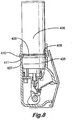
Figure 8 is a similar view of yet a further dispenser according to another embodiment of the invention; and -
Figure 9 is a similar view of the last described dispenser according to another embodiment of the invention. - Referring first to
Figures 1 &2 of the drawings, adispenser 1 comprises acan 2 and abody 3. The can is an aluminium extrusion with a valve crimped into its mouth, the valve having anoutlet spout 4. The crimpedregion 5 of the can surrounding the valve has a lesser diameter than the can has through themain part 6 of its length. - The body has a
mouthpiece 11 with apivotal cover 12 drivingly connected to acam 13. This bears on the underside of ajunction member 14, into asocket 15 of which thespout 4 fits. A breath actuateddose release mechanism 16 is provided. Its details form no part of the present invention. The reader is referred our International Application mentioned at the beginning of this specification for details of this mechanism. - The body has a
tubular section 7 for receiving the necked downregion 5 of the can. The tubular section and the main part of the can having the same external diameter. - A printed
paper label 21 coated with self-adhesive is wrapped around the joint between the body and the can to unite the can to the body in position such that when the cover is opened, a dose is dispensed by thecam 13 lifting the junction member and depressing the spout. The dose is retained since the action of opening of the cover sets the breath actuation mechanism. On breathing in through the mouthpiece by the user, the mechanism releases the dose for inhalation. - In order to establish correct positioning of the can with respect to the body, prior to positioning of the label, during assembly of the dispenser, the
pre-assembled body 3, cover 12,junction member 14 andrelease mechanism 16 are set to their "cover open" position as shown inFigure 3 , i.e. with the cover pivoted down from theFigure 1 position When the dispenser comes to be used, theFigure 3 position is one in which with the can united to the body, the release mechanism is lifted to move thespout 4 inwards of the can, i.e. the spout is depressed. With the mentioned components set to their "cover open" position a can is introduced into the tubular section of the body. With the can and body properly aligned, the spout engages in thesocket 15 in the junction member. A predetermined force F is applied to ensure that the spout is fully depressed. This causes the can to release into the release mechanism a dose, which will usually be a metered dose. Thus in this position of the can in the body, when the cover is opened in use, another dose will be released. With the force still applied the label is applied to the can and the body fixing their relative position. - The label can pass fully around the can or merely pass most of the way around.
- Once the can and the body are united by the label, air can be drawn into a duct D close to the mouthpiece to induce the release mechanism to release the dose. The cover can then be closed and the dispenser is ready for shipping and use. Alternatively, the cover can be closed without induced release. The closure causes a
finger 22 fast with the cam to engage with afinger 23 fast with theflap 24 of the release mechanism whereby the flap is moved to itsFigure 1 position and the dose is released. - It should be noted that whereas a superficial inspection of
Figures 1 and3 might suggest that the can is located by abutment between theend 25 of the tubular section of the body and thestep 26 in the can, there is clearance between these features when the can is pushed in to its position in which spout is depressed and the release mechanism is set. - Alternatively the label can be a
shrink wrap label 31, as shown inFigure 4 . This is of particular advantage where the body stands slightly proud of the can, as shown inFigure 3 , in that a taperedportion 32 of the label bridges the change in diameter from the largerdiameter tubular section 33 to the smaller diameter can 34. The tapered portion acts in tension in use of the device. To enhance grip of the shrink wrap, the can and body can be provided with adhesive 35 and/orsurface formations 36. - Referring to
Figure 5 of the drawings, thedispenser 101 thereshown comprises acan 102 and abody 103. As with the dispenser ofFigure 1 , the can is an aluminium extrusion with a valve crimped into its mouth, the valve having anoutlet spout 104. The crimpedferrule 105 connecting the valve to themain part 106 of the can has a lesser diameter than the can has through the main part of its length. - The body has a
mouthpiece 111 with apivotal cover 112 drivingly connected to acam 113. This bears on the underside of ajunction member 114, into asocket 115 of which thespout 104 fits. A breath actuateddose release mechanism 116 is provided. The body has atubular section 107 for receiving theferrule 105 of the can. The tubular section and the main part of the can having the same external diameter. - The ferrule is made of aluminium with a
coating 121 of polypropylene of sufficient thickness that it can be ultrasonically welded 122 to thetubular section 107 of the body. The can is welded into the body in such position that when the cover is opened, a dose is dispensed by thecam 13 lifting the junction member and depressing the spout. The dose is retained since the action of opening of the cover sets the breath actuation mechanism. On breathing in through the mouthpiece by the user, the mechanism releases the dose for inhalation. - In order to establish the correct positioning prior to welding, during assembly of the dispenser, the
pre-assembled body 103,cover 112,junction member 114 andrelease mechanism 116 are set to their "cover open" position, i.e. with the cover pivoted down from theFigure 5 position, in which in the presence of the can the release mechanism is lifted to depress thespout 104. The can is introduced into the tubular section of the body. With the can and body properly aligned, the spout engages in thesocket 115 in the junction member. A predetermined force is applied to ensure that the spout is fully depressed. This causes the can to release into the release mechanism a dose, which will usually be a metered dose. Thus in this position of the can in the body, when the cover is opened in use, another dose will be released. With the force still applied the can is ultrasonically welded in position. -
Figure 6 shows an alternative, in which thetubular body section 207 is longer and the can proper 206 has the same diameter as the ferrule 205. Both the ferrule and the can are spray coated with polypropylene whereby aweld 222 can be established with thesection 207, both at the ferrule and the portion of the can within the tublar body section. -
Figure 7 yet another alternative where the "can" proper 306 is of glass and spray coated with polypropylene. This is welded 322 to thebody section 307 surrounding it. -
Figure 8 shows another glued dispenser. It has anaperture 410 in itstubular section 407, through which low temperature hot melt adhesive or fast curing two-part adhesive can be injected to set in thegroove 409 between thecrimped portion 405 of the can and themain body portion 406. Afurther groove 408 can be provided in the tubular section, to provide a larger cross-sectional area flow path for the adhesive and also to provide a re-entrant key in both the body and the source for the adhesive, whereby the adhesive 411 locates the source in the body not only by its adhesive nature, but also as a solid block keying into both the features. It can also be envisaged that, where the source has little or no groove at the joint between the crimped on valve for the spout and the can proper, the re-entrant groove in thetubular section 407 may be relied on alone to provide the flow passage for the adhesive. -
Figure 9 shows a further dispenser according to another embodiment of the invention, with asource locator 550. It is a plastics injection moulding. It surrounds thecan 506 with a generallycylindrical sleeve 551 along the length of the can extending from thetubular section 507 of thebody 503. The sleeve of the locator has an in-turnedclosure 552 at its end remote from thebody 503. The can is a loose fit within the locator sleeve, which allows positioning force F on the sleeve to be conveyed to the can of the source for its correct positioning. The polymers of the locator and of the body are chosen whereby the sleeve is transparent to laser irradiation, whilst the body absorbs the radiation, thus melting and forming aweld 553 with the locator, at theiroverlap 504 when the parts are properly located and irradiated for locating the can and the body. - The invention is not intended to be restricted to the details of the above described embodiment. For instance, the weld can be replaced by adhesive. Further the embodiment of
Figure 4 can be varied with the shrink wrapping extending along the full length of the source - shown in dashed lines inFigure 4 - and just over itsend 41. Thus the shrink wrapping holds the can not only by friction along its length but by physical location where it forms arim 42 at the end of the can.
Claims (29)
- A dispenser (1, 101) for a gaseous, gas borne or droplet substance contained in a source thereof, the dispenser comprising:• a substance source (2, 34, 102, 206, 306, 406, 506) having:∘ an external surface (5, 105, 205) devoid of any feature intended for longitudinal location of the source and∘ a spout (4, 104) displaceable inwards of the source to a fully depressed dispense position for dispensing a substance dose from the source;• a body (3, 103, 503) having:∘ a mouthpiece (11, 111) via which the substance dose can be inhaled and∘ a socket (7, 33, 107, 207, 307, 407, 507) sized for lateral location of the source via its external surface, but devoid of any body feature intended for longitudinal location thereof;• a junction member (14, 15, 114, 115) for the spout, the junction member being arranged in the body to be slidable to a set position for displacing the spout to its fully depressed dispense position;• an action (12, 13, 112, 113) for slidably moving the junction member to the set position; and• a unification (21, 31, 32, 41, 42, 121, 122, 222, 322, 411, 553) of the source or a source locator (550, 551, 552) to the body which locates the source longitudinally with the spout in its fully depressed dispense position when the junction member is in its set position, the locator where provided extending from the body, outside the source and at least partially across the end of the source to provide a longitudinal location for the source, locating it when the movable junction member acts to fully depress the spout inwards of the source.
- A dispenser as claimed in claim 1, wherein the unification is an adhesive (411) between the source (405, 406) or the locator and the body (407).
- A dispenser as claimed in claim 2, wherein the adhesive (411) is in the socket of the body (407).
- A dispenser as claimed in claim 2 or claim 3, wherein the body (407) and/or the source (405, 406) or the locator have a re-entrant feature (408, 409) and the body or the locator has an aperture (410) communicating with the re-entrant feature through which the adhesive was injected.
- A dispenser as claimed in claim 4, wherein the re-entrant feature is an internal groove (408) in the body or the locator for receiving the adhesive for a bond with the source (405, 406) or the body (407) respectively.
- A dispenser as claimed in claim 4, wherein the re-entrant feature is an external groove (409) in the source at a crimp (405) for retaining the spout and the source (406).
- A dispenser as claimed in claim 1, wherein the unification is a weld (122, 222, 322, 553) between the source or the locator and the body.
- A dispenser as claimed in claim 7, wherein weld is an ultrasonic weld (122) or a laser weld (553).
- A dispenser as claimed in claim 7 or claim 8, wherein the source and/or the locator and the body are of plastics material.
- A dispenser as claimed in claim 7 or claim 8, wherein the source is of glass or metal and is coated with plastics material.
- A dispenser as claimed in claim 7 or claim 8 wherein the source is of un-coated glass or metal.
- A dispenser as claimed in any one of claims 7 to 11, wherein the weld (222, 322) is between a container of the source and the body.
- A dispenser as claimed in any one of claims 7 to 11, wherein the weld (122, 222) is between a ferrule of the source and the body.
- A dispenser as claimed in any one of claims 7 to 11, wherein the weld (553) is between source locator and the body (504).
- A dispenser as claimed in any preceding claim, wherein the unification is a membrane (21, 31, 32, 41, 42) around both the source or the locator and the body and unified to both.
- A dispenser as claimed in claim 15, wherein the membrane is a wrapping (31, 32, 41, 42).
- A dispenser as claimed in claim 15, wherein the membrane is a printed label (21).
- A dispenser as claimed in claim 15, claim 16 or claim 17, wherein the membrane is of paper (21).
- A dispenser as claimed in claim 15, claim 16 or claim 17, wherein the membrane is of plastics material.
- A dispenser as claimed in any one of claims 15 to 19, wherein the membrane (21, 31, 32) is circumferentially continuous around the body.
- A dispenser as claimed in claim 15, wherein the membrane is a shrink wrapping (31, 32, 41, 42).
- A dispenser as claimed in any one of claims 15 to 19, wherein the membrane (41, 42) is discontinuous around the source or the locator and the body.
- A dispenser as claimed in claim 22, wherein two or more separate membranes (41, 42) could be used, one to one side of the source or the locator and the body and the other to the other side.
- A dispenser as claimed in any one of claims 15 to 23, wherein the or each membrane (21) has self-adhesive applied to it.
- A dispenser as claimed in any one of claims 15 to 23, wherein the or each membrane is of self adhesive material.
- A dispenser as claimed in any one of claims 15 to 23, wherein adhesive (35) for the membrane is applied directly to the source or the locator and the body.
- A dispenser as claimed in any one of claims 15 to 23, wherein the source or the locator and/or the body are contoured (36) to enhance the grip of the membrane to them.
- A method in the production of a dispenser (1,101) as claimed in any one of claims 1 to 27, the method consisting in the steps of:• arranging the junction member (14, 15, 114, 115) in the body (3, 103, 503) at its set position;• longitudinally assembling the source (2, 34, 102, 206, 306, 406, 506) to the body, with the spout (4, 104) engaged with the junction member;• temporarily holding (F) the body and the source in a unification position with the spout in its fully depressed dispense position and the junction member still in its set position; and• unifying (21, 31, 32, 41, 42, 121, 122, 222, 322, 411, 553) the body and the source together to fix them in their unified position.
- A method as claimed in claim 28, wherein the source and the body are relatively located in the temporary holding step by urging the source towards the junction member with a force (F) sufficient to fully depress the spout towards the source and dispense a dose of the substance to the junction member.
Priority Applications (1)
| Application Number | Priority Date | Filing Date | Title |
|---|---|---|---|
| SI200332538T SI2143458T1 (en) | 2002-03-22 | 2003-03-17 | Can fixture |
Applications Claiming Priority (3)
| Application Number | Priority Date | Filing Date | Title |
|---|---|---|---|
| GB0206811A GB0206811D0 (en) | 2002-03-22 | 2002-03-22 | Source mixture |
| GB0227489A GB0227489D0 (en) | 2002-11-26 | 2002-11-26 | Source fixture |
| EP03708349.0A EP1487523B1 (en) | 2002-03-22 | 2003-03-17 | Can fixture |
Related Parent Applications (2)
| Application Number | Title | Priority Date | Filing Date |
|---|---|---|---|
| EP03708349.0A Division EP1487523B1 (en) | 2002-03-22 | 2003-03-17 | Can fixture |
| EP03708349.0A Division-Into EP1487523B1 (en) | 2002-03-22 | 2003-03-17 | Can fixture |
Publications (2)
| Publication Number | Publication Date |
|---|---|
| EP2143458A1 EP2143458A1 (en) | 2010-01-13 |
| EP2143458B1 true EP2143458B1 (en) | 2017-05-10 |
Family
ID=28456026
Family Applications (2)
| Application Number | Title | Priority Date | Filing Date |
|---|---|---|---|
| EP09172349.4A Expired - Lifetime EP2143458B1 (en) | 2002-03-22 | 2003-03-17 | Can fixture |
| EP03708349.0A Expired - Lifetime EP1487523B1 (en) | 2002-03-22 | 2003-03-17 | Can fixture |
Family Applications After (1)
| Application Number | Title | Priority Date | Filing Date |
|---|---|---|---|
| EP03708349.0A Expired - Lifetime EP1487523B1 (en) | 2002-03-22 | 2003-03-17 | Can fixture |
Country Status (17)
| Country | Link |
|---|---|
| US (1) | US7814900B2 (en) |
| EP (2) | EP2143458B1 (en) |
| JP (1) | JP4422794B2 (en) |
| CN (1) | CN100406078C (en) |
| AU (1) | AU2003212529B2 (en) |
| BR (1) | BR0303652A (en) |
| CA (1) | CA2479145C (en) |
| CY (2) | CY1119179T1 (en) |
| DK (2) | DK1487523T3 (en) |
| ES (2) | ES2636622T3 (en) |
| GB (1) | GB2401321B (en) |
| HU (2) | HUE033735T2 (en) |
| MX (1) | MXPA04009152A (en) |
| NO (1) | NO334928B1 (en) |
| PT (2) | PT1487523T (en) |
| SI (2) | SI1487523T1 (en) |
| WO (1) | WO2003080161A1 (en) |
Families Citing this family (16)
| Publication number | Priority date | Publication date | Assignee | Title |
|---|---|---|---|---|
| GB0328859D0 (en) * | 2003-12-12 | 2004-01-14 | Clinical Designs Ltd | Dispenser and counter |
| JP4940127B2 (en) | 2004-03-10 | 2012-05-30 | グラクソ グループ リミテッド | Dosing device |
| GB0425518D0 (en) | 2004-11-19 | 2004-12-22 | Clinical Designs Ltd | Substance source |
| US7350520B1 (en) | 2004-12-03 | 2008-04-01 | Linda C Richard-Bey | Nebulizer delivery device |
| GB0428204D0 (en) | 2004-12-23 | 2005-01-26 | Clinical Designs Ltd | Medicament container |
| GB0518355D0 (en) | 2005-09-08 | 2005-10-19 | Glaxo Group Ltd | An inhaler |
| GB0518400D0 (en) | 2005-09-09 | 2005-10-19 | Clinical Designs Ltd | Dispenser |
| US8123082B2 (en) | 2008-01-22 | 2012-02-28 | McNeil-AB | Hand-held dispensing device |
| JP5339794B2 (en) * | 2008-07-04 | 2013-11-13 | キヤノン株式会社 | Inhaler |
| GB0904059D0 (en) | 2009-03-10 | 2009-04-22 | Euro Celtique Sa | Counter |
| GB0904040D0 (en) * | 2009-03-10 | 2009-04-22 | Euro Celtique Sa | Counter |
| GB2471646B (en) * | 2009-05-11 | 2011-08-10 | Consort Medical Plc | Improvements in or relating to dispensing devices |
| US10016568B2 (en) * | 2009-11-25 | 2018-07-10 | Boehringer Ingelheim International Gmbh | Nebulizer |
| GB201118842D0 (en) | 2011-11-01 | 2011-12-14 | Euro Celtique Sa | Dispenser cap arrangement |
| GB201118845D0 (en) | 2011-11-01 | 2011-12-14 | Euro Celtique Sa | Dispenser |
| GB201702408D0 (en) * | 2017-02-14 | 2017-03-29 | Norton (Waterford) Ltd | Inhalers and related methods |
Family Cites Families (209)
| Publication number | Priority date | Publication date | Assignee | Title |
|---|---|---|---|---|
| GB161969A (en) | 1921-04-18 | 1922-07-18 | Johannes Bretschneider | Inhaler |
| DE629163C (en) | 1934-01-04 | 1936-04-23 | Leyland And Birmingham Rubber | Valve for hollow bodies with flexible valve hose that can be closed by kinking |
| US2002835A (en) * | 1934-05-11 | 1935-05-28 | William H Rose | Siphon device |
| US2716013A (en) * | 1948-11-24 | 1955-08-23 | Theodore B Tinker | Flexible valve structure |
| US2922613A (en) * | 1951-06-01 | 1960-01-26 | Cutter Lab | Pinch valve |
| US2773631A (en) | 1952-01-16 | 1956-12-11 | Paul M Bryant | Measuring and dispensing devices for containers |
| CH297931A (en) | 1952-04-01 | 1954-04-15 | Nationale Sa | Tube-burner for liquefied gas lighter. |
| US2771631A (en) | 1953-11-12 | 1956-11-27 | Hartford Nat Bank & Trust Comp | Apparatus for recovery of crab meat |
| CH365596A (en) | 1957-09-14 | 1962-11-15 | Gauthier Gmbh A | Machine tool with workpiece carrier that can be switched by one full turn |
| US2974835A (en) * | 1959-02-12 | 1961-03-14 | Milton B Herbrick | Self-sealing receptacle closure |
| FR78023E (en) | 1960-07-04 | 1962-05-26 | Bruneau & Cie Lab | Flow control device in a deformable tube |
| US3103335A (en) | 1961-03-28 | 1963-09-10 | Resiflex Lab Inc | Unitary clamp means for flexible tubes |
| US3181743A (en) * | 1961-06-19 | 1965-05-04 | Sidney M Libit | Dispensing closures of the collapsible wall type |
| US3190497A (en) * | 1962-05-28 | 1965-06-22 | Warner Lambert Pharmaceutical | Liquid collecting apparatus and a valve therefor |
| GB1012565A (en) | 1962-06-13 | 1965-12-08 | Goddard & Sons Ltd J | Improvements in or relating to liquid flow control valves |
| NL297349A (en) | 1962-08-31 | |||
| NL299788A (en) | 1962-11-05 | |||
| US3187748A (en) * | 1963-04-29 | 1965-06-08 | Merck And Company Inc | Inhalation-actuated aerosol device |
| US3329389A (en) * | 1964-03-09 | 1967-07-04 | Plastronics Inc | Valve for controlling flow through a flexible tube |
| US3305144A (en) * | 1965-03-01 | 1967-02-21 | Valve Corp Of America | Dispenser for disposable aerosol container, with valved conduit for remote dischargeof its contents |
| US3395838A (en) * | 1965-03-01 | 1968-08-06 | Valve Corp Of America | Manually operable dispenser valve |
| US3294293A (en) | 1965-11-29 | 1966-12-27 | Lever Brothers Ltd | Closure-actuator for container with flexible tubular spout |
| US3456644A (en) | 1967-01-19 | 1969-07-22 | Dart Ind Inc | Inhalation-actuated aerosol dispensing device |
| US3456646A (en) * | 1967-01-19 | 1969-07-22 | Dart Ind Inc | Inhalation-actuated aerosol dispensing device |
| US3439846A (en) * | 1967-06-26 | 1969-04-22 | David J Evras | Nonleak,nonspillable bottle cap |
| DE1915525A1 (en) | 1968-03-26 | 1970-06-11 | Breveteam Sa | Process for changing foam and foam modified by the process |
| US3565070A (en) * | 1969-02-28 | 1971-02-23 | Riker Laboratories Inc | Inhalation actuable aerosol dispenser |
| US3605738A (en) | 1969-06-20 | 1971-09-20 | Paul J Ciranna | Medicinal spray device |
| US3636949A (en) * | 1969-08-08 | 1972-01-25 | Armstrong Kropp Dev Corp | Inhalation-initiated aerosol dispenser |
| GB1383761A (en) * | 1971-02-25 | 1974-02-12 | Woodcraft Dc | Inhalation device for use with an aerosol container |
| NO134730L (en) * | 1971-07-19 | 1900-01-01 | ||
| US3789943A (en) * | 1971-10-12 | 1974-02-05 | Int Harvester Co | Vehicle drive and power control means |
| IT970102B (en) | 1972-10-31 | 1974-04-10 | Crnospital Spa | MICRO DOSING DEVICE FOR REGULATING THE FLOW OF FLUIDS IN FLEXIBLE HOSES |
| US3927484A (en) * | 1974-02-04 | 1975-12-23 | Gilbreth Co | Die-cut coupon shrink label |
| US3926339A (en) | 1974-06-21 | 1975-12-16 | Nat Can Corp | Liquid dispensing apparatus having plural can piercing tools |
| US3926347A (en) | 1974-07-10 | 1975-12-16 | Jaclo Inc | Flowable material dispenser with resilient container |
| US4085886A (en) * | 1977-01-03 | 1978-04-25 | The Procter & Gamble Company | Reclosable twin-Z-fold dispensing valve construction for a liquid containing film pouch |
| US4109836A (en) | 1977-02-10 | 1978-08-29 | Anna Falarde | Self-sealing paste dispensing device |
| US4142651A (en) * | 1977-04-29 | 1979-03-06 | Norbert Leopoldi | Fluid dispenser with flexible outlet tube and pinching valve |
| JPS5682322A (en) * | 1979-12-10 | 1981-07-06 | Tokai:Kk | Valve device for gas lighter |
| FR2483262B1 (en) | 1980-05-30 | 1985-01-25 | Fumakilla Ltd | |
| DE3166709D1 (en) | 1980-08-04 | 1984-11-22 | Fisons Plc | Inhalation device for administering medicaments |
| US4354660A (en) | 1981-02-02 | 1982-10-19 | Baxter Travenol Laboratories Inc. | In-line flow control clamp |
| US4393884A (en) * | 1981-09-25 | 1983-07-19 | Jacobs Allen W | Demand inhaler for oral administration of tobacco, tobacco-like, or other substances |
| CH663829A5 (en) * | 1982-03-15 | 1988-01-15 | Alfred Staeubli | CATHETER VALVE. |
| DE3324699C1 (en) | 1983-07-08 | 1984-12-06 | B. Braun Melsungen Ag, 3508 Melsungen | Valve device |
| US4576157A (en) * | 1983-10-24 | 1986-03-18 | Raghuprasad Puthalath K | Oral inhalation apparatus |
| GB8328808D0 (en) * | 1983-10-28 | 1983-11-30 | Riker Laboratories Inc | Inhalation responsive dispensers |
| WO1985002346A1 (en) | 1983-11-28 | 1985-06-06 | Vortran Corporation | Gas-powered nebulizer |
| US4648393A (en) * | 1984-11-02 | 1987-03-10 | Ackrad Laboratories, Inc. | Breath activated medication spray |
| US5042526A (en) | 1984-12-03 | 1991-08-27 | Kulakoff Alexander E | Valveless toilet |
| US4972830A (en) | 1985-07-31 | 1990-11-27 | Vortran Medical Technology, Inc. | Inhalation device and method |
| US4803978A (en) * | 1985-08-09 | 1989-02-14 | Johnson Iv John J | Apparatus for actuating an inhaler |
| US4707038A (en) | 1986-01-08 | 1987-11-17 | Voegeli Ronald C | Display rack |
| NZ219021A (en) | 1986-01-27 | 1989-06-28 | Gea Farmaceutisk Fabrik As | Inhaler: medicine discharged intermittently during each inhalation |
| DE3663331D1 (en) | 1986-04-23 | 1989-06-22 | Ake Timerdahl | A valve arrangement for controlling the supply of pressurized-air, water and/or other media to hand-operated tools, preferably instruments for dental work |
| FI871799A (en) | 1986-04-25 | 1987-10-26 | Glaxo Group Ltd | INDIKERINGSANORDNING. |
| US4703761A (en) | 1986-08-04 | 1987-11-03 | Rathbone R Rodion | Blood sampling device for obtaining small quantity of venous blood |
| US4819834A (en) * | 1986-09-09 | 1989-04-11 | Minnesota Mining And Manufacturing Company | Apparatus and methods for delivering a predetermined amount of a pressurized fluid |
| CA1311170C (en) | 1987-05-12 | 1992-12-08 | Glaxo, Inc. | Inhalation device |
| US5031610A (en) * | 1987-05-12 | 1991-07-16 | Glaxo Inc. | Inhalation device |
| US5119806A (en) * | 1987-05-12 | 1992-06-09 | Glaxo Inc. | Inhalation device |
| DE3734894C1 (en) | 1987-10-15 | 1989-01-26 | Braun Melsungen Ag | Attachment with valve |
| DE8715223U1 (en) | 1987-11-17 | 1988-02-04 | Bundesrepublik Deutschland, Vertreten Durch Den Bundesminister Der Verteidigung, Dieser Vertreten Durch Den Praesidenten Des Bundesamtes Fuer Wehrtechnik Und Beschaffung, 5400 Koblenz, De | |
| GB8810898D0 (en) | 1988-05-09 | 1988-06-15 | Bespak Plc | Improvements in dispensing apparatus |
| US4984158A (en) * | 1988-10-14 | 1991-01-08 | Hillsman Dean | Metered dose inhaler biofeedback training and evaluation system |
| US5299701A (en) * | 1989-02-03 | 1994-04-05 | Senetics, Inc. | Indicator cap |
| US5421482A (en) * | 1989-02-03 | 1995-06-06 | Senetics, Inc. | Indicator device responsive to axial force |
| US5193745A (en) * | 1989-03-07 | 1993-03-16 | Karl Holm | Atomizing nozzle device for atomizing a fluid and an inhaler |
| GB8909891D0 (en) * | 1989-04-28 | 1989-06-14 | Riker Laboratories Inc | Device |
| AU643435B2 (en) | 1989-04-28 | 1993-11-18 | Riker Laboratories, Inc. | Dry powder inhalation device |
| US4955371A (en) | 1989-05-08 | 1990-09-11 | Transtech Scientific, Inc. | Disposable inhalation activated, aerosol device for pulmonary medicine |
| US5297542A (en) * | 1989-06-22 | 1994-03-29 | Raymond J. Bacon | Aerosol dispensing device |
| GB8914383D0 (en) | 1989-06-22 | 1989-08-09 | Bell Susan J | Inhalation-actuated aerosol dispensing device |
| US5042685A (en) | 1989-08-10 | 1991-08-27 | Moulding Jr Thomas S | Dispensing having a compartment for detecting and counting the dispensed objects especially adapted for dispensing medication and method of using the same |
| GB8919131D0 (en) | 1989-08-23 | 1989-10-04 | Riker Laboratories Inc | Inhaler |
| GB8925707D0 (en) | 1989-11-14 | 1990-01-04 | Riker Laboratories Inc | Device |
| FR2654627B1 (en) | 1989-11-23 | 1992-02-28 | Micro Mega Sa | FLOW REGULATING DEVICE, PARTICULARLY FOR MEDICAL OR DENTAL USE. |
| US5152456A (en) | 1989-12-12 | 1992-10-06 | Bespak, Plc | Dispensing apparatus having a perforate outlet member and a vibrating device |
| FR2658081B1 (en) * | 1990-02-09 | 1995-06-30 | Pesenti Yvan | AUTOMATION AND SYNCHRONIZATION DEVICE FOR AEROSOL APPARATUS WITH DOSING PUMP. |
| US5113855A (en) * | 1990-02-14 | 1992-05-19 | Newhouse Michael T | Powder inhaler |
| US5020527A (en) * | 1990-02-20 | 1991-06-04 | Texax-Glynn Corporation | Inhaler device with counter/timer means |
| FR2660630B1 (en) | 1990-04-10 | 1993-06-04 | Bielsteiner France | DEVICE FOR DISPENSING A FLUID OR PASTY PRODUCT CONTAINED IN A CRUSHABLE TUBE. |
| EP0461281A1 (en) | 1990-06-12 | 1991-12-18 | Atochem North America, Inc. | Device for detecting air flow through a passageway |
| GB9015077D0 (en) | 1990-07-09 | 1990-08-29 | Riker Laboratories Inc | Inhaler |
| US5060643A (en) | 1990-08-07 | 1991-10-29 | Tenax Corporation | Breath-activated inhalation device |
| GB9020555D0 (en) * | 1990-09-20 | 1990-10-31 | Bespak Plc | Dispensing apparatus |
| GB9024760D0 (en) * | 1990-11-14 | 1991-01-02 | Riker Laboratories Inc | Inhalation device and medicament carrier |
| GB9026191D0 (en) | 1990-12-01 | 1991-01-16 | Harris Pharma Ltd | Breath actuated dispensing device |
| US5217004A (en) * | 1990-12-13 | 1993-06-08 | Tenax Corporation | Inhalation actuated dispensing apparatus |
| EP0563120B1 (en) * | 1990-12-17 | 1997-10-01 | Minnesota Mining And Manufacturing Company | Inhaler |
| DE4105939A1 (en) | 1991-02-26 | 1992-08-27 | Sigismund Laskowski | METHOD AND DEVICE FOR DOSING LIQUID SUBSTANCES FROM A DISPENSING CONTAINER |
| US5404871A (en) | 1991-03-05 | 1995-04-11 | Aradigm | Delivery of aerosol medications for inspiration |
| DE4111895C2 (en) | 1991-04-12 | 1994-10-13 | Sigismund Laskowski | Method and device for closing and pouring liquid substances |
| US5295479A (en) * | 1991-04-15 | 1994-03-22 | Leiras Oy | Device intended for measuring a dose of powdered medicament for inhalation |
| FR2676929B1 (en) | 1991-05-30 | 1994-02-11 | Aerosols Bouchage Ste Fse | POWDER INHALER. |
| DE4136985C1 (en) | 1991-11-11 | 1993-05-13 | Marsteller & Killmann Gmbh & Co Kg, 4300 Essen, De | |
| US5469843A (en) | 1991-11-12 | 1995-11-28 | Minnesota Mining And Manufacturing Company | Inhalation device |
| GB2262452B (en) | 1991-12-19 | 1995-12-20 | Minnesota Mining & Mfg | Inhalation device |
| DE4142238A1 (en) * | 1991-12-20 | 1993-06-24 | Boehringer Ingelheim Kg | POWDER INHALATOR WITH POWDER SUPPORT FROM REGULAR MICROSTRUCTURES |
| DE69319107T2 (en) | 1992-03-25 | 1999-02-25 | Galli Rosaria & C | POWDER DISPENSER FOR MEDICAL INHALATION THERAPIES |
| GB2266466B (en) | 1992-04-08 | 1995-12-20 | Bespak Plc | Inhalation apparatus |
| SE9201411D0 (en) | 1992-05-05 | 1992-05-05 | Astra Ab | DOSAGE INHALATOR WITH INDICATING / INTERUPTING MEANS |
| GB2263873A (en) | 1992-05-29 | 1993-08-11 | Norton Healthcare Ltd | Medicament dispensing device |
| GB2264238A (en) | 1992-05-29 | 1993-08-25 | Norton Healthcare Ltd | Medicament inhalor device |
| GB9214819D0 (en) * | 1992-07-13 | 1992-08-26 | Minnesota Mining & Mfg | Valve assemblies |
| GB9217545D0 (en) * | 1992-08-18 | 1992-09-30 | Minnesota Mining & Mfg | Inhalation device |
| US5402823A (en) * | 1992-12-07 | 1995-04-04 | George S. Cole & Associates, Incorporated | Pinch valve |
| DK0680451T3 (en) * | 1993-01-19 | 1999-07-19 | Glaxo Group Ltd | Aerosol dispenser as well as process of its manufacture |
| FR2701399B1 (en) | 1993-02-16 | 1995-03-31 | Valois | Portable spray device with actuation triggered by inhalation. |
| FR2701653B1 (en) | 1993-02-18 | 1995-04-07 | Valois | Dosing device for the inhalation of dry powder. |
| DE4313319B4 (en) | 1993-04-23 | 2006-09-28 | C. Ehrensperger Ag | Device for actuators for propellant cans |
| GB2279571A (en) | 1993-06-14 | 1995-01-11 | Minnesota Mining & Mfg | Inhaler |
| GB9312494D0 (en) | 1993-06-17 | 1993-08-04 | Lilly Industries Ltd | Improvements in or relating to devices for dispensing articles |
| GB2279879B (en) | 1993-07-14 | 1997-10-08 | Bespak Plc | Medicament inhalers |
| US5415161A (en) * | 1993-09-15 | 1995-05-16 | Ryder; Steven L. | Intermittant demand aerosol control device |
| AU688794B2 (en) * | 1993-09-22 | 1998-03-19 | Senetics, Inc. | Indicator device responsive to axial force |
| US5388572A (en) * | 1993-10-26 | 1995-02-14 | Tenax Corporation (A Connecticut Corp.) | Dry powder medicament inhalator having an inhalation-activated piston to aerosolize dose and deliver same |
| US5370279A (en) | 1994-03-03 | 1994-12-06 | Tardif; Pierre | Squeeze canteen for dispensing a liquid |
| US5839429A (en) | 1994-03-25 | 1998-11-24 | Astra Aktiebolag | Method and apparatus in connection with an inhaler |
| US5501375A (en) * | 1994-05-12 | 1996-03-26 | Cenova Innovations & Produktions Ab | Dispenser valve for dispensing a pressurized liquid |
| US5564414A (en) | 1994-05-26 | 1996-10-15 | Walker; William F. | Pressurized and metered medication dose counter on removable sleeve |
| FR2721106B1 (en) | 1994-06-10 | 1996-09-13 | Step | Dose counter for inhalers. |
| US5857275A (en) * | 1994-06-30 | 1999-01-12 | Deal; Richard E. | Label with enhanced grip |
| GB2292891A (en) | 1994-09-07 | 1996-03-13 | Norton Healthcare Ltd | Actuator for breath-actuated medicament dispenser |
| US5544647A (en) | 1994-11-29 | 1996-08-13 | Iep Group, Inc. | Metered dose inhalator |
| WO1996028367A2 (en) * | 1995-03-10 | 1996-09-19 | Minnesota Mining And Manufacturing Company | Aerosol valves |
| US6205999B1 (en) * | 1995-04-05 | 2001-03-27 | Aerogen, Inc. | Methods and apparatus for storing chemical compounds in a portable inhaler |
| USD377215S (en) * | 1995-04-13 | 1997-01-07 | Glaxo Group Limited | Inhaler |
| US5809997A (en) | 1995-05-18 | 1998-09-22 | Medtrac Technologies, Inc. | Electronic medication chronolog device |
| US5667142A (en) | 1995-05-30 | 1997-09-16 | Newstripe, Inc. | Spray gun with removable supply line |
| AU128811S (en) * | 1995-06-06 | 1996-12-03 | Orion Yhtymae Oy | A protective cover for example a moisture protective cover for a powder inhaler |
| US6672304B1 (en) * | 1995-06-08 | 2004-01-06 | Innovative Devices, Llc | Inhalation actuated device for use with metered dose inhalers (MDIs) |
| US5826571A (en) | 1995-06-08 | 1998-10-27 | Innovative Devices, Llc | Device for use with metered dose inhalers (MDIS) |
| US6357442B1 (en) * | 1995-06-08 | 2002-03-19 | Innovative Devices, Llc | Inhalation actuated device for use with metered dose inhalers (MDIS) |
| DE19525546C2 (en) * | 1995-07-13 | 2002-05-02 | Schott Glas | Device for the administration of substances, in particular inhalation preparations |
| DE29511334U1 (en) | 1995-07-13 | 1995-11-02 | Schott Glaswerke | Device for the administration of substances, in particular inhalation preparations |
| US5823183A (en) | 1995-08-02 | 1998-10-20 | Innovative Devices | Dry powder medicament inhalator having an inhalation-activated flow diverting means for triggering delivery of medicament |
| JP3317823B2 (en) | 1995-08-11 | 2002-08-26 | 株式会社ユニシアジェックス | Dosing device |
| DE19549033C1 (en) | 1995-12-28 | 1997-05-28 | Boehringer Ingelheim Int | Mechanical counter for a dosing device |
| ATE216903T1 (en) | 1996-02-21 | 2002-05-15 | Schering Corp | INHALER FOR POWDER-TYPE MEDICATION |
| FR2750780B1 (en) * | 1996-07-05 | 1998-10-30 | Valois | DOSER COUNTER |
| US5707038A (en) * | 1996-10-23 | 1998-01-13 | Cocatre-Zilgien; Jan H. | Hinged kink valve |
| WO1998031411A1 (en) | 1997-01-17 | 1998-07-23 | Bo Drachmann | Aerosol inhaler device |
| GB9705657D0 (en) * | 1997-03-19 | 1997-05-07 | Bacon Raymond J | Dispenser |
| US5904139A (en) * | 1997-03-28 | 1999-05-18 | Hauser; Stephen G. | Breath coordinated inhaler |
| US5794612A (en) | 1997-04-02 | 1998-08-18 | Aeromax Technologies, Inc. | MDI device with ultrasound sensor to detect aerosol dispensing |
| US6085742A (en) * | 1997-04-02 | 2000-07-11 | Aeromax Technologies, Inc. | Intrapulmonary delivery device |
| WO1998052634A1 (en) * | 1997-05-23 | 1998-11-26 | Pa Knowledge Limited | Inhaler mechanism |
| TW533865U (en) | 1997-06-10 | 2003-05-21 | Glaxo Group Ltd | Dispenser for dispensing medicament and actuation indicating device |
| EP1008362A4 (en) | 1997-07-28 | 2000-08-23 | Japan Co Ltd Dr | Mandrin of medical anesthetic needle and method of manufacturing same |
| US6309623B1 (en) * | 1997-09-29 | 2001-10-30 | Inhale Therapeutic Systems, Inc. | Stabilized preparations for use in metered dose inhalers |
| DE19745513A1 (en) | 1997-10-15 | 1999-04-22 | Walz Karl Heinz | Bottle valve system |
| AU777488B2 (en) | 1997-10-17 | 2004-10-21 | Systemic Pulmonary Delivery, Ltd. | Method and apparatus for delivering aerosolized medication |
| EP1047467B1 (en) | 1998-01-16 | 2004-06-23 | 1263152 Ontario Inc. | Indicating device for use with a dispensing device |
| FR2775668B1 (en) * | 1998-03-04 | 2000-05-19 | Tebro | DEVICE FOR DISPENSING FLUID PRODUCT TRIGGERED BY INHALATION |
| EE200000546A (en) | 1998-03-16 | 2002-02-15 | Inhale Therapeutic Systems, Inc. | Aerosolized drug delivery system |
| SE9801077D0 (en) | 1998-03-27 | 1998-03-27 | Shl Medical Ab | Inhaler |
| GB9807558D0 (en) | 1998-04-09 | 1998-06-10 | Bason Neil P | An indicator device |
| US6082358A (en) | 1998-05-05 | 2000-07-04 | 1263152 Ontario Inc. | Indicating device for aerosol container |
| US6152130A (en) | 1998-06-12 | 2000-11-28 | Microdose Technologies, Inc. | Inhalation device with acoustic control |
| US6260549B1 (en) * | 1998-06-18 | 2001-07-17 | Clavius Devices, Inc. | Breath-activated metered-dose inhaler |
| DE29814647U1 (en) | 1998-08-14 | 1999-12-23 | Wischerath Josef Gmbh Co Kg | Inhaler with a metering device |
| BR9913921A (en) * | 1998-09-24 | 2001-06-19 | Astrazeneca Ab | Inhaler for inhalation drug delivery |
| DE29818662U1 (en) | 1998-10-20 | 2000-03-02 | Wischerath Josef Gmbh Co Kg | inhaler |
| GB9825118D0 (en) | 1998-11-16 | 1999-01-13 | Minnesota Mining & Mfg | Breath-actuated aerosol dispensers |
| GB2344534B (en) * | 1998-12-11 | 2000-10-18 | Bespak Plc | Inhalation apparatus |
| AU140816S (en) | 1999-01-29 | 2000-06-08 | Glaxo Group Ltd | Inhalation device |
| US6196218B1 (en) | 1999-02-24 | 2001-03-06 | Ponwell Enterprises Ltd | Piezo inhaler |
| GB2348928B (en) * | 1999-04-07 | 2001-10-31 | Bespak Plc | Improvements in or relating to dispensing apparatus |
| US6202642B1 (en) * | 1999-04-23 | 2001-03-20 | Medtrac Technologies, Inc. | Electronic monitoring medication apparatus and method |
| GB9911388D0 (en) * | 1999-05-18 | 1999-07-14 | Glaxo Group Ltd | Dispenser |
| SE516826C2 (en) * | 1999-06-18 | 2002-03-05 | Shl Medical Ab | Breath-operated device for use with an inhaler includes a return mechanism for deactivating a canister to close when airflow drops below a certain threshold value |
| SE9902672D0 (en) * | 1999-07-12 | 1999-07-12 | Astra Ab | Delivery device |
| US6615827B2 (en) | 1999-09-08 | 2003-09-09 | Sapphire Designs, Inc. | Inhalation counter device |
| FR2799858B1 (en) | 1999-10-19 | 2002-01-18 | Valois Sa | DOSAGE COUNTER AND FLUID PRODUCT DISPENSER INCORPORATING SUCH A COUNTER |
| AU777964C (en) | 1999-11-10 | 2005-11-17 | Innovative Devices, Llc | Inhalation actuated device for use with metered dose inhalers (MDIs) |
| GB0002798D0 (en) * | 2000-02-09 | 2000-03-29 | Glaxo Group Ltd | Actuator nozzle for metered dose inhaler |
| GB0006525D0 (en) * | 2000-03-18 | 2000-05-10 | Astrazeneca Uk Ltd | Inhaler |
| GB2360216A (en) | 2000-03-18 | 2001-09-19 | Astrazeneca Uk Ltd | Inhaler |
| GB2360219A (en) * | 2000-03-18 | 2001-09-19 | Astrazeneca Uk Ltd | Inhaler |
| US6581590B1 (en) * | 2000-03-21 | 2003-06-24 | Iep Pharmaceutical Devices Inc. | Inhalation actuated device |
| US6637432B2 (en) * | 2000-05-09 | 2003-10-28 | Iep Pharmaceutical Devices Inc. | Inhalation actuated device |
| US20020000225A1 (en) * | 2000-06-02 | 2002-01-03 | Carlos Schuler | Lockout mechanism for aerosol drug delivery devices |
| US6553988B1 (en) * | 2000-06-09 | 2003-04-29 | Norton Healthcare, Inc. | Medicament dispensing device with a multimaterial diaphragm bounding a pneumatic force chamber |
| TWI224514B (en) * | 2000-06-23 | 2004-12-01 | Norton Healthcare Ltd | Dose metering system for medicament inhaler |
| GB0016123D0 (en) * | 2000-07-01 | 2000-08-23 | Glaxo Group Ltd | Valve for aerosol container |
| EP1301230A1 (en) | 2000-07-15 | 2003-04-16 | Glaxo Group Limited | Medicament dispenser |
| PT2263729E (en) * | 2000-07-24 | 2015-12-07 | Clinical Designs Ltd | Dispenser |
| US20020043262A1 (en) * | 2000-08-22 | 2002-04-18 | Alan Langford | Spray device |
| FR2813214B1 (en) * | 2000-08-29 | 2003-05-02 | Valois Sa | IMPROVED FLUID PRODUCT DISPENSING DEVICE |
| SE517228C2 (en) | 2000-09-25 | 2002-05-14 | Microdrug Ag | Dry powder inhaler with respiratory activation |
| DE60141149D1 (en) | 2000-09-29 | 2010-03-11 | Pfizer Ltd | Medical inhalation device |
| US6442234B1 (en) | 2000-10-03 | 2002-08-27 | Advanced Micro Devices, Inc. | X-ray inspection of ball contacts and internal vias |
| GB0025749D0 (en) * | 2000-10-20 | 2000-12-06 | Glaxo Group Ltd | Inhaler |
| GB0026646D0 (en) | 2000-10-31 | 2000-12-13 | Glaxo Group Ltd | Medicament dispenser |
| USD455208S1 (en) * | 2000-12-05 | 2002-04-02 | Clinical Designs Limited | Inhaler |
| DE10061723C2 (en) | 2000-12-12 | 2003-01-16 | Eckert Rosemarie | Counter for counting metered deliveries of liquid, pasty or solid products as well as device for metered dispensing of such products |
| SE0100034D0 (en) | 2001-01-04 | 2001-01-04 | Astrazeneca Ab | A delivery device |
| US20040079361A1 (en) * | 2001-01-17 | 2004-04-29 | Clayton Colin D. | Medicinal aerosols |
| DK1357965T3 (en) * | 2001-01-25 | 2014-12-15 | Clinical Designs Ltd | Dispenser for drug |
| GB0101944D0 (en) * | 2001-01-25 | 2001-03-07 | Bacon Raymond J | Dispenser |
| GB2372541B (en) * | 2001-02-23 | 2003-08-20 | Bespak Plc | Dosage counting devices |
| GB0108228D0 (en) | 2001-04-02 | 2001-05-23 | Glaxo Group Ltd | Medicament dispenser |
| GB0109717D0 (en) * | 2001-04-20 | 2001-06-13 | Glaxo Group Ltd | Medicament dispenser |
| AU2002322314B2 (en) * | 2001-06-26 | 2006-08-17 | Norton Healthcare, Ltd. | An improved aerosol actuator |
| USD480474S1 (en) | 2001-11-01 | 2003-10-07 | Astrazeneca Ab | Inhaler |
| US7322352B2 (en) * | 2002-09-21 | 2008-01-29 | Aventis Pharma Limited | Inhaler |
| AU158576S (en) | 2003-07-05 | 2006-08-22 | Clinical Designs Ltd | Inhaler |
-
2003
- 2003-03-17 DK DK03708349.0T patent/DK1487523T3/en active
- 2003-03-17 EP EP09172349.4A patent/EP2143458B1/en not_active Expired - Lifetime
- 2003-03-17 ES ES09172349.4T patent/ES2636622T3/en not_active Expired - Lifetime
- 2003-03-17 EP EP03708349.0A patent/EP1487523B1/en not_active Expired - Lifetime
- 2003-03-17 HU HUE03708349A patent/HUE033735T2/en unknown
- 2003-03-17 BR BR0303652-9A patent/BR0303652A/en not_active Application Discontinuation
- 2003-03-17 AU AU2003212529A patent/AU2003212529B2/en not_active Ceased
- 2003-03-17 WO PCT/GB2003/001102 patent/WO2003080161A1/en active Application Filing
- 2003-03-17 MX MXPA04009152A patent/MXPA04009152A/en active IP Right Grant
- 2003-03-17 PT PT37083490T patent/PT1487523T/en unknown
- 2003-03-17 HU HUE09172349A patent/HUE033736T2/en unknown
- 2003-03-17 US US10/508,688 patent/US7814900B2/en not_active Expired - Fee Related
- 2003-03-17 PT PT91723494T patent/PT2143458T/en unknown
- 2003-03-17 CN CNB038067277A patent/CN100406078C/en not_active Expired - Fee Related
- 2003-03-17 GB GB0420197A patent/GB2401321B/en not_active Expired - Fee Related
- 2003-03-17 CA CA2479145A patent/CA2479145C/en not_active Expired - Fee Related
- 2003-03-17 SI SI200332537T patent/SI1487523T1/en unknown
- 2003-03-17 DK DK09172349.4T patent/DK2143458T3/en active
- 2003-03-17 JP JP2003577985A patent/JP4422794B2/en not_active Expired - Fee Related
- 2003-03-17 ES ES03708349.0T patent/ES2633913T3/en not_active Expired - Lifetime
- 2003-03-17 SI SI200332538T patent/SI2143458T1/en unknown
- 2003-11-18 NO NO20035131A patent/NO334928B1/en not_active IP Right Cessation
-
2017
- 2017-07-31 CY CY20171100819T patent/CY1119179T1/en unknown
- 2017-07-31 CY CY20171100818T patent/CY1119201T1/en unknown
Also Published As
| Publication number | Publication date |
|---|---|
| AU2003212529A1 (en) | 2003-10-08 |
| GB2401321A (en) | 2004-11-10 |
| SI2143458T1 (en) | 2017-09-29 |
| SI1487523T1 (en) | 2017-09-29 |
| JP2005520647A (en) | 2005-07-14 |
| NO20035131D0 (en) | 2003-11-18 |
| US7814900B2 (en) | 2010-10-19 |
| EP1487523A1 (en) | 2004-12-22 |
| BR0303652A (en) | 2004-07-13 |
| GB0420197D0 (en) | 2004-10-13 |
| CA2479145A1 (en) | 2003-10-02 |
| NO334928B1 (en) | 2014-07-14 |
| DK1487523T3 (en) | 2017-08-28 |
| EP2143458A1 (en) | 2010-01-13 |
| CY1119179T1 (en) | 2018-02-14 |
| PT2143458T (en) | 2017-08-07 |
| JP4422794B2 (en) | 2010-02-24 |
| HUE033736T2 (en) | 2018-01-29 |
| ES2633913T3 (en) | 2017-09-26 |
| PT1487523T (en) | 2017-07-25 |
| CN1642592A (en) | 2005-07-20 |
| AU2003212529B2 (en) | 2008-07-10 |
| CA2479145C (en) | 2011-06-14 |
| NO20035131L (en) | 2004-01-02 |
| CN100406078C (en) | 2008-07-30 |
| ES2636622T3 (en) | 2017-10-06 |
| HUE033735T2 (en) | 2018-01-29 |
| MXPA04009152A (en) | 2005-12-14 |
| GB2401321B (en) | 2005-12-07 |
| EP1487523B1 (en) | 2017-05-10 |
| CY1119201T1 (en) | 2018-02-14 |
| WO2003080161A1 (en) | 2003-10-02 |
| US20070163576A1 (en) | 2007-07-19 |
| DK2143458T3 (en) | 2017-09-04 |
Similar Documents
| Publication | Publication Date | Title |
|---|---|---|
| EP2143458B1 (en) | Can fixture | |
| US10195374B2 (en) | Container, nebulizer and use | |
| EP3331775B1 (en) | Method for assembling a dispensing system for dispensing a fluid medium | |
| US6145703A (en) | Spray applicator | |
| EP1419014B1 (en) | Safety closure for a container | |
| JP5433689B2 (en) | Overcap and start-up method for volatile substance dispensers | |
| EP2105209B1 (en) | Apparatus for dispensing fluids using a press-fit dip tube | |
| MX2012013552A (en) | Aerosol generator. | |
| CN105641787A (en) | Dose container | |
| EP3331776B1 (en) | Valve cups and containers for use in fluid medium dispensing systems | |
| EP3408192B1 (en) | Aerosol valve configurations | |
| ZA200407573B (en) | Can fixture | |
| US20200093178A1 (en) | Cartridge for an aerosol generating device and method for making said cartridge | |
| US20050072809A1 (en) | Method of sealing a plug with a food sauce dispensing cartridge | |
| CA2272886A1 (en) | Actuator cap for an aerosol dispenser |
Legal Events
| Date | Code | Title | Description |
|---|---|---|---|
| PUAI | Public reference made under article 153(3) epc to a published international application that has entered the european phase |
Free format text: ORIGINAL CODE: 0009012 |
|
| AC | Divisional application: reference to earlier application |
Ref document number: 1487523 Country of ref document: EP Kind code of ref document: P |
|
| AK | Designated contracting states |
Kind code of ref document: A1 Designated state(s): AT BE BG CH CY CZ DE DK EE ES FI FR GB GR HU IE IT LI LU MC NL PT RO SE SI SK TR |
|
| REG | Reference to a national code |
Ref country code: HK Ref legal event code: DE Ref document number: 1134459 Country of ref document: HK |
|
| 17P | Request for examination filed |
Effective date: 20100608 |
|
| 17Q | First examination report despatched |
Effective date: 20100706 |
|
| GRAP | Despatch of communication of intention to grant a patent |
Free format text: ORIGINAL CODE: EPIDOSNIGR1 |
|
| INTG | Intention to grant announced |
Effective date: 20161121 |
|
| GRAS | Grant fee paid |
Free format text: ORIGINAL CODE: EPIDOSNIGR3 |
|
| GRAA | (expected) grant |
Free format text: ORIGINAL CODE: 0009210 |
|
| AC | Divisional application: reference to earlier application |
Ref document number: 1487523 Country of ref document: EP Kind code of ref document: P |
|
| AK | Designated contracting states |
Kind code of ref document: B1 Designated state(s): AT BE BG CH CY CZ DE DK EE ES FI FR GB GR HU IE IT LI LU MC NL PT RO SE SI SK TR |
|
| REG | Reference to a national code |
Ref country code: GB Ref legal event code: FG4D |
|
| REG | Reference to a national code |
Ref country code: AT Ref legal event code: REF Ref document number: 891647 Country of ref document: AT Kind code of ref document: T Effective date: 20170515 Ref country code: CH Ref legal event code: EP |
|
| REG | Reference to a national code |
Ref country code: IE Ref legal event code: FG4D |
|
| REG | Reference to a national code |
Ref country code: DE Ref legal event code: R096 Ref document number: 60350228 Country of ref document: DE |
|
| REG | Reference to a national code |
Ref country code: NL Ref legal event code: FP |
|
| REG | Reference to a national code |
Ref country code: RO Ref legal event code: EPE |
|
| REG | Reference to a national code |
Ref country code: PT Ref legal event code: SC4A Ref document number: 2143458 Country of ref document: PT Date of ref document: 20170807 Kind code of ref document: T Free format text: AVAILABILITY OF NATIONAL TRANSLATION Effective date: 20170731 |
|
| REG | Reference to a national code |
Ref country code: SE Ref legal event code: TRGR |
|
| REG | Reference to a national code |
Ref country code: DK Ref legal event code: T3 Effective date: 20170829 |
|
| REG | Reference to a national code |
Ref country code: ES Ref legal event code: FG2A Ref document number: 2636622 Country of ref document: ES Kind code of ref document: T3 Effective date: 20171006 |
|
| REG | Reference to a national code |
Ref country code: EE Ref legal event code: FG4A Ref document number: E014128 Country of ref document: EE Effective date: 20170808 |
|
| REG | Reference to a national code |
Ref country code: SK Ref legal event code: T3 Ref document number: E 25171 Country of ref document: SK |
|
| REG | Reference to a national code |
Ref country code: HU Ref legal event code: AG4A Ref document number: E033736 Country of ref document: HU |
|
| REG | Reference to a national code |
Ref country code: GR Ref legal event code: EP Ref document number: 20170402037 Country of ref document: GR Effective date: 20180119 |
|
| REG | Reference to a national code |
Ref country code: DE Ref legal event code: R097 Ref document number: 60350228 Country of ref document: DE |
|
| REG | Reference to a national code |
Ref country code: HU Ref legal event code: HC9C |
|
| PLBE | No opposition filed within time limit |
Free format text: ORIGINAL CODE: 0009261 |
|
| STAA | Information on the status of an ep patent application or granted ep patent |
Free format text: STATUS: NO OPPOSITION FILED WITHIN TIME LIMIT |
|
| REG | Reference to a national code |
Ref country code: FR Ref legal event code: PLFP Year of fee payment: 16 |
|
| 26N | No opposition filed |
Effective date: 20180213 |
|
| REG | Reference to a national code |
Ref country code: HK Ref legal event code: GR Ref document number: 1134459 Country of ref document: HK |
|
| PGFP | Annual fee paid to national office [announced via postgrant information from national office to epo] |
Ref country code: LU Payment date: 20190325 Year of fee payment: 17 Ref country code: CZ Payment date: 20190226 Year of fee payment: 17 Ref country code: GB Payment date: 20190320 Year of fee payment: 17 Ref country code: FR Payment date: 20190322 Year of fee payment: 17 Ref country code: IE Payment date: 20190322 Year of fee payment: 17 Ref country code: IT Payment date: 20190325 Year of fee payment: 17 Ref country code: RO Payment date: 20190225 Year of fee payment: 17 Ref country code: DE Payment date: 20190321 Year of fee payment: 17 Ref country code: MC Payment date: 20190314 Year of fee payment: 17 Ref country code: FI Payment date: 20190321 Year of fee payment: 17 Ref country code: CH Payment date: 20190320 Year of fee payment: 17 Ref country code: BG Payment date: 20190321 Year of fee payment: 17 |
|
| PGFP | Annual fee paid to national office [announced via postgrant information from national office to epo] |
Ref country code: TR Payment date: 20190301 Year of fee payment: 17 Ref country code: HU Payment date: 20190322 Year of fee payment: 17 Ref country code: SE Payment date: 20190320 Year of fee payment: 17 Ref country code: DK Payment date: 20190322 Year of fee payment: 17 Ref country code: GR Payment date: 20190326 Year of fee payment: 17 Ref country code: SI Payment date: 20190218 Year of fee payment: 17 Ref country code: AT Payment date: 20190321 Year of fee payment: 17 Ref country code: BE Payment date: 20190320 Year of fee payment: 17 Ref country code: NL Payment date: 20190320 Year of fee payment: 17 Ref country code: EE Payment date: 20190318 Year of fee payment: 17 |
|
| PGFP | Annual fee paid to national office [announced via postgrant information from national office to epo] |
Ref country code: SK Payment date: 20190227 Year of fee payment: 17 |
|
| PGFP | Annual fee paid to national office [announced via postgrant information from national office to epo] |
Ref country code: PT Payment date: 20190225 Year of fee payment: 17 Ref country code: CY Payment date: 20190313 Year of fee payment: 17 Ref country code: ES Payment date: 20190418 Year of fee payment: 17 |
|
| REG | Reference to a national code |
Ref country code: DE Ref legal event code: R119 Ref document number: 60350228 Country of ref document: DE |
|
| REG | Reference to a national code |
Ref country code: FI Ref legal event code: MAE |
|
| REG | Reference to a national code |
Ref country code: EE Ref legal event code: MM4A Ref document number: E014128 Country of ref document: EE Effective date: 20200331 |
|
| PG25 | Lapsed in a contracting state [announced via postgrant information from national office to epo] |
Ref country code: MC Free format text: LAPSE BECAUSE OF NON-PAYMENT OF DUE FEES Effective date: 20200331 Ref country code: FI Free format text: LAPSE BECAUSE OF NON-PAYMENT OF DUE FEES Effective date: 20200317 Ref country code: PT Free format text: LAPSE BECAUSE OF NON-PAYMENT OF DUE FEES Effective date: 20200917 Ref country code: CZ Free format text: LAPSE BECAUSE OF NON-PAYMENT OF DUE FEES Effective date: 20200317 Ref country code: CY Free format text: LAPSE BECAUSE OF NON-PAYMENT OF DUE FEES Effective date: 20200317 Ref country code: RO Free format text: LAPSE BECAUSE OF NON-PAYMENT OF DUE FEES Effective date: 20200317 |
|
| REG | Reference to a national code |
Ref country code: CH Ref legal event code: PL |
|
| REG | Reference to a national code |
Ref country code: DK Ref legal event code: EBP Effective date: 20200331 |
|
| REG | Reference to a national code |
Ref country code: NL Ref legal event code: MM Effective date: 20200401 |
|
| REG | Reference to a national code |
Ref country code: AT Ref legal event code: MM01 Ref document number: 891647 Country of ref document: AT Kind code of ref document: T Effective date: 20200317 |
|
| REG | Reference to a national code |
Ref country code: SK Ref legal event code: MM4A Ref document number: E 25171 Country of ref document: SK Effective date: 20200317 |
|
| REG | Reference to a national code |
Ref country code: BE Ref legal event code: MM Effective date: 20200331 |
|
| PG25 | Lapsed in a contracting state [announced via postgrant information from national office to epo] |
Ref country code: NL Free format text: LAPSE BECAUSE OF NON-PAYMENT OF DUE FEES Effective date: 20200401 Ref country code: LU Free format text: LAPSE BECAUSE OF NON-PAYMENT OF DUE FEES Effective date: 20200317 |
|
| REG | Reference to a national code |
Ref country code: SI Ref legal event code: KO00 Effective date: 20201113 |
|
| PG25 | Lapsed in a contracting state [announced via postgrant information from national office to epo] |
Ref country code: LI Free format text: LAPSE BECAUSE OF NON-PAYMENT OF DUE FEES Effective date: 20200331 Ref country code: DE Free format text: LAPSE BECAUSE OF NON-PAYMENT OF DUE FEES Effective date: 20201001 Ref country code: IE Free format text: LAPSE BECAUSE OF NON-PAYMENT OF DUE FEES Effective date: 20200317 Ref country code: SE Free format text: LAPSE BECAUSE OF NON-PAYMENT OF DUE FEES Effective date: 20200318 Ref country code: EE Free format text: LAPSE BECAUSE OF NON-PAYMENT OF DUE FEES Effective date: 20200331 Ref country code: GR Free format text: LAPSE BECAUSE OF NON-PAYMENT OF DUE FEES Effective date: 20201008 Ref country code: FR Free format text: LAPSE BECAUSE OF NON-PAYMENT OF DUE FEES Effective date: 20200331 Ref country code: CH Free format text: LAPSE BECAUSE OF NON-PAYMENT OF DUE FEES Effective date: 20200331 Ref country code: BG Free format text: LAPSE BECAUSE OF NON-PAYMENT OF DUE FEES Effective date: 20201130 Ref country code: AT Free format text: LAPSE BECAUSE OF NON-PAYMENT OF DUE FEES Effective date: 20200317 Ref country code: HU Free format text: LAPSE BECAUSE OF NON-PAYMENT OF DUE FEES Effective date: 20200318 |
|
| PG25 | Lapsed in a contracting state [announced via postgrant information from national office to epo] |
Ref country code: SI Free format text: LAPSE BECAUSE OF NON-PAYMENT OF DUE FEES Effective date: 20200318 Ref country code: SK Free format text: LAPSE BECAUSE OF NON-PAYMENT OF DUE FEES Effective date: 20200317 Ref country code: BE Free format text: LAPSE BECAUSE OF NON-PAYMENT OF DUE FEES Effective date: 20200331 |
|
| GBPC | Gb: european patent ceased through non-payment of renewal fee |
Effective date: 20200317 |
|
| PG25 | Lapsed in a contracting state [announced via postgrant information from national office to epo] |
Ref country code: DK Free format text: LAPSE BECAUSE OF NON-PAYMENT OF DUE FEES Effective date: 20200331 Ref country code: GB Free format text: LAPSE BECAUSE OF NON-PAYMENT OF DUE FEES Effective date: 20200317 |
|
| REG | Reference to a national code |
Ref country code: ES Ref legal event code: FD2A Effective date: 20210730 |
|
| PG25 | Lapsed in a contracting state [announced via postgrant information from national office to epo] |
Ref country code: IT Free format text: LAPSE BECAUSE OF NON-PAYMENT OF DUE FEES Effective date: 20200317 |
|
| PG25 | Lapsed in a contracting state [announced via postgrant information from national office to epo] |
Ref country code: ES Free format text: LAPSE BECAUSE OF NON-PAYMENT OF DUE FEES Effective date: 20200318 |
|
| PG25 | Lapsed in a contracting state [announced via postgrant information from national office to epo] |
Ref country code: TR Free format text: LAPSE BECAUSE OF NON-PAYMENT OF DUE FEES Effective date: 20200317 |