EP2142397B1 - Vorrichtung und verfahren zur steuerung einer shunt-stromschaltung und hybridfahrzeug damit - Google Patents
Vorrichtung und verfahren zur steuerung einer shunt-stromschaltung und hybridfahrzeug damit Download PDFInfo
- Publication number
- EP2142397B1 EP2142397B1 EP08805721A EP08805721A EP2142397B1 EP 2142397 B1 EP2142397 B1 EP 2142397B1 EP 08805721 A EP08805721 A EP 08805721A EP 08805721 A EP08805721 A EP 08805721A EP 2142397 B1 EP2142397 B1 EP 2142397B1
- Authority
- EP
- European Patent Office
- Prior art keywords
- curve
- generator
- motor
- machines
- inverters
- Prior art date
- Legal status (The legal status is an assumption and is not a legal conclusion. Google has not performed a legal analysis and makes no representation as to the accuracy of the status listed.)
- Active
Links
Images
Classifications
-
- H—ELECTRICITY
- H02—GENERATION; CONVERSION OR DISTRIBUTION OF ELECTRIC POWER
- H02M—APPARATUS FOR CONVERSION BETWEEN AC AND AC, BETWEEN AC AND DC, OR BETWEEN DC AND DC, AND FOR USE WITH MAINS OR SIMILAR POWER SUPPLY SYSTEMS; CONVERSION OF DC OR AC INPUT POWER INTO SURGE OUTPUT POWER; CONTROL OR REGULATION THEREOF
- H02M7/00—Conversion of ac power input into dc power output; Conversion of dc power input into ac power output
- H02M7/42—Conversion of dc power input into ac power output without possibility of reversal
- H02M7/44—Conversion of dc power input into ac power output without possibility of reversal by static converters
- H02M7/48—Conversion of dc power input into ac power output without possibility of reversal by static converters using discharge tubes with control electrode or semiconductor devices with control electrode
- H02M7/53—Conversion of dc power input into ac power output without possibility of reversal by static converters using discharge tubes with control electrode or semiconductor devices with control electrode using devices of a triode or transistor type requiring continuous application of a control signal
- H02M7/537—Conversion of dc power input into ac power output without possibility of reversal by static converters using discharge tubes with control electrode or semiconductor devices with control electrode using devices of a triode or transistor type requiring continuous application of a control signal using semiconductor devices only, e.g. single switched pulse inverters
- H02M7/5387—Conversion of dc power input into ac power output without possibility of reversal by static converters using discharge tubes with control electrode or semiconductor devices with control electrode using devices of a triode or transistor type requiring continuous application of a control signal using semiconductor devices only, e.g. single switched pulse inverters in a bridge configuration
- H02M7/53871—Conversion of dc power input into ac power output without possibility of reversal by static converters using discharge tubes with control electrode or semiconductor devices with control electrode using devices of a triode or transistor type requiring continuous application of a control signal using semiconductor devices only, e.g. single switched pulse inverters in a bridge configuration with automatic control of output voltage or current
-
- B—PERFORMING OPERATIONS; TRANSPORTING
- B60—VEHICLES IN GENERAL
- B60L—PROPULSION OF ELECTRICALLY-PROPELLED VEHICLES; SUPPLYING ELECTRIC POWER FOR AUXILIARY EQUIPMENT OF ELECTRICALLY-PROPELLED VEHICLES; ELECTRODYNAMIC BRAKE SYSTEMS FOR VEHICLES IN GENERAL; MAGNETIC SUSPENSION OR LEVITATION FOR VEHICLES; MONITORING OPERATING VARIABLES OF ELECTRICALLY-PROPELLED VEHICLES; ELECTRIC SAFETY DEVICES FOR ELECTRICALLY-PROPELLED VEHICLES
- B60L50/00—Electric propulsion with power supplied within the vehicle
- B60L50/50—Electric propulsion with power supplied within the vehicle using propulsion power supplied by batteries or fuel cells
- B60L50/51—Electric propulsion with power supplied within the vehicle using propulsion power supplied by batteries or fuel cells characterised by AC-motors
-
- H—ELECTRICITY
- H02—GENERATION; CONVERSION OR DISTRIBUTION OF ELECTRIC POWER
- H02M—APPARATUS FOR CONVERSION BETWEEN AC AND AC, BETWEEN AC AND DC, OR BETWEEN DC AND DC, AND FOR USE WITH MAINS OR SIMILAR POWER SUPPLY SYSTEMS; CONVERSION OF DC OR AC INPUT POWER INTO SURGE OUTPUT POWER; CONTROL OR REGULATION THEREOF
- H02M5/00—Conversion of ac power input into ac power output, e.g. for change of voltage, for change of frequency, for change of number of phases
- H02M5/40—Conversion of ac power input into ac power output, e.g. for change of voltage, for change of frequency, for change of number of phases with intermediate conversion into dc
- H02M5/42—Conversion of ac power input into ac power output, e.g. for change of voltage, for change of frequency, for change of number of phases with intermediate conversion into dc by static converters
- H02M5/44—Conversion of ac power input into ac power output, e.g. for change of voltage, for change of frequency, for change of number of phases with intermediate conversion into dc by static converters using discharge tubes or semiconductor devices to convert the intermediate dc into ac
- H02M5/453—Conversion of ac power input into ac power output, e.g. for change of voltage, for change of frequency, for change of number of phases with intermediate conversion into dc by static converters using discharge tubes or semiconductor devices to convert the intermediate dc into ac using devices of a triode or transistor type requiring continuous application of a control signal
- H02M5/458—Conversion of ac power input into ac power output, e.g. for change of voltage, for change of frequency, for change of number of phases with intermediate conversion into dc by static converters using discharge tubes or semiconductor devices to convert the intermediate dc into ac using devices of a triode or transistor type requiring continuous application of a control signal using semiconductor devices only
- H02M5/4585—Conversion of ac power input into ac power output, e.g. for change of voltage, for change of frequency, for change of number of phases with intermediate conversion into dc by static converters using discharge tubes or semiconductor devices to convert the intermediate dc into ac using devices of a triode or transistor type requiring continuous application of a control signal using semiconductor devices only having a rectifier with controlled elements
-
- Y—GENERAL TAGGING OF NEW TECHNOLOGICAL DEVELOPMENTS; GENERAL TAGGING OF CROSS-SECTIONAL TECHNOLOGIES SPANNING OVER SEVERAL SECTIONS OF THE IPC; TECHNICAL SUBJECTS COVERED BY FORMER USPC CROSS-REFERENCE ART COLLECTIONS [XRACs] AND DIGESTS
- Y02—TECHNOLOGIES OR APPLICATIONS FOR MITIGATION OR ADAPTATION AGAINST CLIMATE CHANGE
- Y02T—CLIMATE CHANGE MITIGATION TECHNOLOGIES RELATED TO TRANSPORTATION
- Y02T10/00—Road transport of goods or passengers
- Y02T10/60—Other road transportation technologies with climate change mitigation effect
- Y02T10/70—Energy storage systems for electromobility, e.g. batteries
Definitions
- the invention relates to a device for controlling a power bypass circuit of a hybrid vehicle.
- One field of application of the invention is the road hybrid vehicles.
- the document US-B-6,486,632 describes a device comprising first and second inverters whose continuous sides are connected to a DC voltage storage unit, the reciprocating sides of which are intended to be connected to first and second polyphase electrical machines intended to be coupled to the mechanical transmission of the vehicle, the first machine being able to operate as a motor and the second machine being able to function as a generator for the power bypass from the transmission, the inverters further comprising cutting switches for converting between the continuous sides and the sides the device comprising a harmonic filtering capacitor on the continuous sides of the inverters and a control unit for the switching switches, comprising a control mode thereof by pulse width modulation of a carrier having a identical frequency for the inverters.
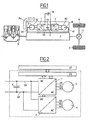
- FIG. figure 1 two electric machines 3, 4 are connected to a mechanical transmission 5 connected to wheels 6, 7 on one side and to a system 8 for storing energy on the other side.
- Two inverters 1, 2 are used to control the machines 3, 4.
- the internal combustion engine is shut down, one of the two machines 3, 4 is used to drive the transmission.
- a common filtering capacitor C is usually mounted on the DC bus between the two inverters 1, 2.
- the inverters 1, 2 cut by opening and closing their switches the DC voltage to generate AC voltages that feed the machines 3, 4. It is called MLI cutting (modulation of the pulse width).
- the high-frequency cutting (a few kHz) generates harmonics in addition to the fundamental useful on the currents of the machines, and in the same way widens the spectrum of the current generated on the DC bus 10.
- the capacitor C filters most of these current harmonics to return as much continuous current as possible to the storage element.
- the aging of the capacitance is sensitive to its heating, and therefore to the effective current flowing through it. It is therefore interesting to control the current to be filtered and its harmonic content.
- a first object of the invention is to optimize the pulse width modulation control of the inverters.
- a second objective of the invention is to minimize the current ripple of the capacitor, as well as the effective current flowing through it.
- a third objective of the invention is to optimize the voltage of the phases of the machines.
- a first object of the invention is a device for controlling a power bypass circuit of a hybrid vehicle, the device comprising first and second inverters whose continuous sides are connected to a DC voltage storage unit, the reciprocating sides of which are intended to be connected to first and second polyphase electrical machines intended to be coupled to the mechanical transmission of the vehicle, the first machine being able to function as a generator and the second machine being able to operate as a motor for the power bypass from the transmission, the inverters further comprising cutting switches for the conversion between continuous sides and reciprocating sides, device comprising a harmonic filtering capacitor on the continuous sides of the inverters and a control unit for the chopper switches, comprising at least one control mode thereof by width modulation pulses of a carrier having an identical frequency for the inverters, characterized in that the first and second machines are able to operate as engine / engine or generator / generator, the control unit comprises means for detecting the operation of the first and second engine / engine or generator / generator machines and first means of control of the switching switches of the second inverter
- a second object of the invention is a method of controlling a power bypass circuit on board a hybrid vehicle, for the implementation of the control device as described above, using first and second inverters whose continuous sides are connected to a DC voltage storage unit, the alternating sides of which are connected to first and second polyphase electrical machines, coupled to the mechanical transmission of the vehicle, the first machine operating as a generator and the second machine operating in a motor for deriving power from the transmission, the inverters further comprising switching switches for converting between the DC and AC sides, a harmonic filtering capability being provided on the continuous sides of the inverters, the cutting being controlled by a control unit having at least one com mode Mande thereof by pulse width modulation of a carrier having an identical frequency for the inverters, characterized in that the first and second machines are operated as engine / engine or generator / generator, the switching switches of the second inverter are controlled in a temporally offset manner with respect to the switching switches of the first inverter in the event of operation of the first and second machines in motor / motor or in
- a third object of the invention is a hybrid vehicle, comprising an internal combustion engine for driving wheels via a mechanical transmission, the mechanical transmission being coupled to first and second electric machines, the first machine being able to operate as a generator and the second machine being able to operate as a motor to form a power bypass circuit from the transmission, characterized in that the first and second electrical machines are connected to an on-board control device as described herein. -above.
- the electrical machines 3, 4 are for example three-phase and each comprise three distinct phases U1, V1, W1, and U2, V2, W2, respectively connected to the alternating side AC of the inverters 1 and 2.
- the machines 3, 4 comprise respectively a movable portion 31, 41, which is mechanically connected to the transmission 5 and which is movable relative to the mechanical part 32, 42 connected to the phases U1, V1, W1, U2, V2, W2.
- the machine 3 When the internal combustion engine 9 operates to mechanically drive the transmission 5 to rotate the wheels 6, 7 through a differential 11, the machine 3 operates as a generator and derives electrical power from the transmission 5 to the alternating AC side of the inverter 1 as represented by the arrow F1, this derived electrical power being converted into direct current on the DC side DC of the inverter 1 to store energy in the storage element 8.
- the other machine 4 then operates as a motor for this power bypass.
- the element 8 of energy storage is for example formed by one or more rechargeable electric batteries, or one or more super-capacitors, as is known.
- the internal combustion engine can also drive the wheels with the machine 3 into the engine and the machine 4 into a generator. The choice of motor / generator or generator / motor modes is chosen by the supervisor.
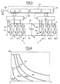
- the inverters 1, 2 respectively comprise switches I1, 12 for cutting the DC current present on their AC DC side on the phases U1, V1, W1 and U2, V2, W2.
- each inverter 1, 2 comprises, for each phase, two switches I1 or 12 in series between the two conductors 10 of the DC bus, the node between the two switches I1 or 12 being connected to the phase U1, V1 or W1, U2, V2 or W2.
- Each switch I1, 12 is for example formed by a transistor type IGBT (insulated gate bipolar transistor) in parallel with which is provided a diode in reverse.
- Each switch I1, I2 has an input E1, E2 to control its opening or closing, this input being formed for the IGBT transistors by their gate.
- the control inputs E1 of the switches I1 of the inverter 1 are connected to a first control circuit 21, while the control inputs E2 of the switches I2 of the inverter 2 are connected to a second control circuit 22.
- the first and second control circuits 21, 22 are connected to a low level control unit 23, comprising a first carrier generation module 24, which is sent to the first circuit 21, and a second carrier generation circuit 25. , which is sent to the second circuit 22.
- the unit 23 comprises one or more computers 26, in particular for the control of the modules 24 and 25.
- the low level control unit 23 is connected to a control unit 27 high level of the vehicle.
- the will of the driver and / or the vehicle control strategy determine the torques and / or speeds applied to the electric machines 3, 4.
- the clipping strategy is selected to solve the problem of reducing the size of the filtering capacitor C, without overly complicating the low-layer control and without impacting the performance of the vehicle.
- Another object is to reduce the current harmonics whose effective current is at the origin of the heating and aging of the C capacity of filtering.
- a "clean" sinusoidal voltage is also desired at the machine terminals.
- the choice of the type of control depends first of all on the speed and the torque demanded from the machines and is selected by the computer 26.
- the vector PWM command is no longer the application of 3 voltages independent of each other as the scalar PWM but as a strategy for driving the rotating vector of a three-phase (or polyphase) system, therefore with pulse synchronization between phases.
- One of the main advantages of this strategy is to be able to provide a fundamental tension greater than that which could be delivered by three juxtaposed independent scalar strategies.
- the full-wave control is preferred when the amplitude of the voltages can not be reached by the other control modes.
- the supply voltage is applied alternately to each pole of the load at the fundamental frequency that is desired. There is thus a maximum amplitude of AC voltage across the terminals of the machines. It is thus possible to reach the areas of high power (torque) at the cost of a current overload (additional losses) due to the low frequency harmonics of the voltage.
- the transitions between the modes are decided according to the electrical losses and their distribution between machine losses and inverter losses.
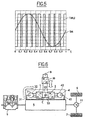
- the figure 4 illustrates different cases of operation.
- the control mode MLI1 scalar is delimited from the point O of zero velocity V and zero CM torque by a first curve C1 torque depending on the speed.
- the second mode MLI2 of vector control is delimited by the curve C1 and a second curve C2 for values of speed V and / or torque CM increasing with respect to the curve C1.
- the third mode MLI3 control over-modulated vector is delimited by the curve C2 and a third curve C3 for values of speed V and / or torque CM increasing with respect to the curve C2.
- the fourth full-wave control mode PO is delimited by the curve C3 and a fourth curve C4 for values of speed V and / or torque CM increasing with respect to the curve C3.
- the curves C1, C2, C3, C4 are decreasing, for example in the manner of hyperbolas.
- the fourth curve C4 is a torque envelope curve of the engine machine.
- the carrier generation module 25 sends to the control circuit 22 of the inverter 2 a carrier shifted by half a period, that is to say in phase opposition, with respect to the carrier of the same frequency sent by the generation module 24 to the control circuit 21 of the inverter 1.
- the carriers sent to the inverters 1 and 2 have the same frequency and are shifted by half a period between them.
- the equilibrium of the phase currents of the two machines is preferred. That is to say that the "high level" control chooses the corresponding torque for the same current on each machine, the sum of the couples being transmitted to the wheel. Typically, this is possible in ZEV driving mode.
- Torques applied to the motor are controlled by the "high level" control.
- the carriers of the two inverters have the same phase and the same frequency.
- the structure may comprise a DC / DC converter between the capacitor C and the storage element 8 so as to have an optimum DC bus voltage for the inverters 1, 2 and 3, 4 d on the one hand, and make this voltage insensitive to the voltage variations of the storage element 8 on the other hand.
- the frequency of the hash harmonics from the DC / DC converter 30 must be of higher frequency than the inverters, which is most of the time the case.
- the low-frequency harmonics of the filtered current will be of a rank greater than 6 times the fundamental frequency of the phase current (twice the number of phases).
- the gap is reduced between the switching harmonics and the harmonics due to the fundamental of the phase current. This may lead to increase the frequency of cutting compared to a three-phase system if this gap is insufficient.
Claims (10)
- Vorrichtung zur Steuerung einer Leistungsverzweigungsschaltung eines Hybridfahrzeugs,
wobei die Vorrichtung einen ersten und einen zweiten Wechselrichter (1, 2) umfasst, deren Gleichspannungsseiten mit einer Einheit (8) zur Speicherung einer Gleichspannung verbunden sind, deren Wechselspannungsseiten mit einer ersten und einer zweiten mehrphasigen elektrischen Maschine (3, 4) verbunden werden sollen, die mit dem mechanischen Getriebe (5) des Fahrzeugs gekoppelt werden sollen, wobei die erste Maschine (3) als Generator funktionieren kann und die zweite Maschine (4) als Motor für die Leistungsverzweigung vom Getriebe (5) funktionieren kann, wobei die Wechselrichter (1, 2) außerdem Schaltunterbrecher für die Umwandlung zwischen den Gleichspannungsseiten und den Wechselspannungsseiten umfassen, wobei die Vorrichtung eine Kapazität (C) zur Filterung von Oberwellen auf den Gleichspannungsseiten der Wechselrichter (1, 2) und eine Einheit (23) zur Steuerung der Schaltunterbrecher mit mindestens einem Steuermodus dieser durch Impulsbreitenmodulation einer Trägerwelle mit einer identischen Frequenz für die Wechselrichter (1, 2) umfasst, wobei die Einheit (23) zur Steuerung der Wechselrichter außerdem ein Mittel (26) zur Steuerung ihrer Schaltunterbrecher (I1, I2) gemäß einem Modus (MLI2) zur vektoriellen Impulsbreitenmodulation umfasst,
dadurch gekennzeichnet, dass
die erste und die zweite Maschine (3, 4) als Motor/Motor oder als Generator/Generator funktionieren können, die Steuereinheit (23) Mittel (MD) zur Detektion der Funktion der ersten und der zweiten Maschine (3, 4) als Motor/Motor oder als Generator/Generator und erste Mittel (24, 25) zur Steuerung der Schaltunterbrecher (I2) des zweiten Wechselrichters (2) in einer zeitlich in Bezug auf die Schaltunterbrecher (I1) des ersten Wechselrichters (1) versetzten Weise im Fall der Detektion der Funktion der ersten und der zweiten Maschine (3, 4) als Motor/Motor oder als Generator/Generator umfasst, und außerdem die Einheit (23) zur Steuerung der der Wechselrichter Folgendes umfasst- einen ersten Modus (MLI1) zur Steuerung ihrer Schaltunterbrecher (I1, I2) durch skalare Impulsbreitenmodulation,- einen zweiten Modus (MLI2) zur Steuerung ihrer
I2) durch vektorielle Impulsbreitenmodulation,- einen dritten Modus (MLI3) zur Steuerung ihrer Schaltunterbrecher (I1, I2) durch übersteuerte Impulsbreitenmodulation und- einen vierten Ganzwellenmodus (PO) zur Steuerung ihrer Schaltunterbrecher (I1, I2). - Steuervorrichtung nach Anspruch 1, dadurch gekennzeichnet, dass der zeitliche Versatz zwischen dem zweiten Wechselrichter (2) und dem ersten Wechselrichter (1) einer Halbperiode der Trägerwelle entspricht.
- Steuervorrichtung nach einem der vorhergehenden Ansprüche, dadurch gekennzeichnet, dass die Steuereinheit (23) ein Mittel (26) zur Auswahl eines Modus zum Anwenden des ersten, des zweiten, des dritten oder des vierten Modus auf die Wechselrichter (1, 2) für zugehörige Werte von Geschwindigkeiten und Drehmomenten der Maschinen (3, 4) umfasst, die in einem ersten, zweiten, dritten bzw. vierten benachbarten Bereich von zunehmenden Werten liegen.
- Steuervorrichtung nach Anspruch 3, dadurch gekennzeichnet, dass der erste skalare Steuermodus (MLI1) von dem Punkt (O) der Geschwindigkeit (V) von null und des Drehmoments (CM) von null durch eine erste Kurve (C1) des Drehmoments in Abhängigkeit von der Geschwindigkeit begrenzt ist, der zweite vektorielle Steuermodus (MLI2) durch die erste Kurve (C1) und eine zweite Kurve (C2) für in Bezug auf die erste Kurve (C1) zunehmende Werte der Geschwindigkeit (V) und/oder des Drehmoments (CM) begrenzt ist, der dritte übersteuerte vektorielle Steuermodus (MLI3) durch die zweite Kurve (C2) und eine dritte Kurve (C3) für in Bezug auf die zweite Kurve (C2) zunehmende Werte der Geschwindigkeit (V) und/oder des Drehmoments (CM) begrenzt ist, der vierte Ganzwellen-Steuermodus (PO) durch die dritte Kurve (C3) und eine vierte Kurve (C4) für in Bezug auf die dritte Kurve (C3) zunehmende Werte der Geschwindigkeit (V) und/oder des Drehmoments (CM) begrenzt ist, wobei die erste, die zweite, die dritte und die vierte Kurve (C1, C2, C3, C4) abfallen, wobei die vierte Kurve C4 eine Hüllkurve des Drehmoments von einer der als Motor funktionierenden Maschinen ist.
- Steuervorrichtung nach einem der vorhergehenden Ansprüche, dadurch gekennzeichnet, dass die Steuereinheit (23) zusätzlich zu den ersten Steuermitteln (24, 25) Mittel zum Detektieren der Funktion der ersten und der zweiten Maschine (3, 4) als Motor/Generator oder als Generator/Motor und Steuermittel (23) der Schaltunterbrecher (I2) des zweiten Wechselrichters (2) mit derselben zeitlichen Phase wie die Schaltunterbrecher (I1) des ersten Wechselrichters (1) im Fall der Detektion der Funktion der ersten und der zweiten Maschine (3, 4) als Motor/Generator oder als Generator/Motor umfasst.
- Steuervorrichtung nach einem der vorhergehenden Ansprüche, dadurch gekennzeichnet, dass ein Gleichspannungswandler (30) zwischen die Kapazität (C) und die Energiespeichereinheit (8) geschaltet ist.
- Verfahren zum Steuern einer Leistungsverzweigungsschaltung an Bord eines Hybridfahrzeugs für den Einsatz der Steuervorrichtung nach einem der vorhergehenden Ansprüche, die einen ersten und einen zweiten Wechselrichter (1, 2) verwendet, deren Gleichspannungsseiten mit einer Einheit (8) zur Speicherung einer Gleichspannung verbunden sind, deren Wechselspannungsseiten mit einer ersten und einer zweiten mehrphasigen elektrischen Maschine (3, 4) verbunden sind, die mit dem mechanischen Getriebe (5) des Fahrzeugs gekoppelt sind, wobei die erste Maschine (3) als Generator funktioniert und die zweite Maschine (4) als Motor funktioniert, für die Leistungsverzweigung vom Getriebe (5), wobei die Wechselrichter (1, 2) außerdem Schaltunterbrecher für die Umwandlung zwischen den Gleichspannungsseiten und den Wechselspannungsseiten umfassen, wobei eine Kapazität (C) zum Filtern von Oberwellen auf den Gleichspannungsseiten der Wechselrichter (1, 2) vorgesehen ist, wobei die Schaltunterbrecher durch eine Steuereinheit (23) mit mindestens einem Steuermodus dieser durch Impulsbreitenmodulation einer Trägerwelle mit einer identischen Frequenz für die Wechselrichter (1, 2) gesteuert werden,
dadurch gekennzeichnet, dass
die erste und die zweite Maschine (3, 4) als Motor/Motor oder als Generator/Generator funktionieren lassen werden,
die Schaltunterbrecher (I2) des zweiten Wechselrichters (2) in einer zeitlich in Bezug auf die Schaltunterbrecher (I1) des ersten Wechselrichters (1) versetzten Weise im Fall der Funktion der ersten und der zweiten Maschine (3, 4) als Motor/Motor oder als Generator/Generator gesteuert werden,
die Schaltunterbrecher (I1, I2) der Wechselrichter (1, 2) gemäß einem ersten Steuermodus (ML1) durch skalare Impulsbreitenmodulation, gemäß einem zweiten Steuermodus (MLI2) durch vektorielle Impulsbreitenmodulation, gemäß einem dritten Modus (MLI3) durch übersteuerte Impulsbreitenmodulation und gemäß einem vierten Ganzwellen-Steuermodus (PO) für zugehörige Werte von Geschwindigkeiten und Drehmomenten der Maschine (3, 4) gesteuert werden, die in einem ersten, einem zweiten, einem dritten bzw. einem vierten benachbarten Bereich von zunehmenden Werten liegen. - Steuerverfahren nach Anspruch 7, dadurch gekennzeichnet, dass der zeitliche Versatz zwischen dem zweiten Wechselrichter (2) und dem ersten Wechselrichter (1) im Fall der Funktion der ersten und der zweiten Maschine (3, 4) als Motor/Motor oder als Generator/Generator einer Halbperiode der Trägerwelle entspricht.
- Steuerverfahren nach einem der Ansprüche 7 und 8, dadurch gekennzeichnet, dass der erste skalare Steuermodus (MLI1) von einem Punkt (O) der Geschwindigkeit (V) von null und des Drehmoments (CM) von null durch eine erste Kurve (C1) des Drehmoments in Abhängigkeit von der Geschwindigkeit begrenzt ist, der zweite vektorielle Steuermodus (MLI2) durch die erste Kurve (C1) und eine zweite Kurve (C2) für in Bezug auf die erste Kurve (C1) zunehmende Werte der Geschwindigkeit (V) und/oder des Drehmoments (CM) begrenzt ist, der dritte übersteuerte vektorielle Steuermodus (MLI3) durch die zweite Kurve (C2) und eine dritte Kurve (C3) für in Bezug auf die zweite Kurve (C2) zunehmende Werte der Geschwindigkeit (V) und/oder des Drehmoments (CM) begrenzt ist, der vierte Ganzwellen-Steuermodus (PO) durch die dritte Kurve (C3) und eine vierte Kurve (C4) für in Bezug auf die dritte Kurve (C3) zunehmende Werte der Geschwindigkeit (V) und/oder des Drehmoments (CM) begrenzt ist, wobei die erste, die zweite, die dritte und die vierte Kurve (C1, C2, C3, C4) abfallen, wobei die vierte Kurve C4 eine Hüllkurve des Drehmoments von einer der als Motor funktionierenden Maschinen ist.
- Hybridfahrzeug mit einer Brennkraftmaschine (9) für den Antrieb von Rädern (6, 7) durch ein mechanisches Getriebe (5), wobei das mechanische Getriebe (5) mit einer ersten und einer zweiten elektrischen Maschine (3, 4) gekoppelt ist, wobei die erste Maschine (3) als Generator funktionieren kann und die zweite Maschine (4) als Motor funktionieren kann, um eine Schaltung zur Verzweigung von Leistung vom Getriebe (5) zu bilden, dadurch gekennzeichnet, dass die erste und die zweite elektrische Maschine (3, 4) mit einer Bordsteuervorrichtung nach einem der Ansprüche 1 bis 6 verbunden sind.
Applications Claiming Priority (2)
| Application Number | Priority Date | Filing Date | Title |
|---|---|---|---|
| FR0703182A FR2915722B1 (fr) | 2007-05-03 | 2007-05-03 | "dispositif et procede de commande d'un circuit de derivation de puissance, vehicule hybride l'ayant" |
| PCT/FR2008/050767 WO2008148977A2 (fr) | 2007-05-03 | 2008-04-28 | Dispositif et procede de commande d'un circuit de derivation de puissance, vehicule hybride l'ayant |
Publications (2)
| Publication Number | Publication Date |
|---|---|
| EP2142397A2 EP2142397A2 (de) | 2010-01-13 |
| EP2142397B1 true EP2142397B1 (de) | 2012-03-14 |
Family
ID=38855023
Family Applications (1)
| Application Number | Title | Priority Date | Filing Date |
|---|---|---|---|
| EP08805721A Active EP2142397B1 (de) | 2007-05-03 | 2008-04-28 | Vorrichtung und verfahren zur steuerung einer shunt-stromschaltung und hybridfahrzeug damit |
Country Status (7)
| Country | Link |
|---|---|
| US (1) | US8310084B2 (de) |
| EP (1) | EP2142397B1 (de) |
| JP (1) | JP5528327B2 (de) |
| CN (1) | CN101678778B (de) |
| AT (1) | ATE549200T1 (de) |
| FR (1) | FR2915722B1 (de) |
| WO (1) | WO2008148977A2 (de) |
Families Citing this family (13)
| Publication number | Priority date | Publication date | Assignee | Title |
|---|---|---|---|---|
| FR2915722B1 (fr) * | 2007-05-03 | 2009-08-28 | Renault Sas | "dispositif et procede de commande d'un circuit de derivation de puissance, vehicule hybride l'ayant" |
| JP4347377B2 (ja) * | 2007-11-06 | 2009-10-21 | トヨタ自動車株式会社 | ハイブリッド車およびその制御方法 |
| JP5297953B2 (ja) | 2009-09-08 | 2013-09-25 | トヨタ自動車株式会社 | 電動車両の電動機駆動システム |
| DE102010004712A1 (de) * | 2010-01-11 | 2011-07-14 | Dr. Ing. h.c. F. Porsche Aktiengesellschaft, 70435 | Hybridantrieb eines Hybridfahrzeuges |
| JP5984336B2 (ja) | 2011-02-25 | 2016-09-06 | Ntn株式会社 | インホイールモータ車両の駆動装置 |
| US9014300B2 (en) * | 2013-09-12 | 2015-04-21 | Qualcomm Incorporated | Switched-mode high-linearity transmitter using pulse width modulation |
| US10476267B2 (en) * | 2015-11-10 | 2019-11-12 | Caterpillar Inc. | Smart load bank and excitation control |
| CN105471239A (zh) * | 2015-12-31 | 2016-04-06 | 清华大学苏州汽车研究院(吴江) | 一种双电机-逆变器系统母线电容纹波消除方法 |
| US20180145609A1 (en) * | 2016-11-23 | 2018-05-24 | General Electric Company | Hybrid switch for inverter of computed tomography system |
| CN106671970A (zh) * | 2016-12-23 | 2017-05-17 | 广东戈兰玛汽车系统有限公司 | 电动车动力总成中心控制器 |
| FR3062003B1 (fr) * | 2017-01-16 | 2020-01-03 | Valeo Equipements Electriques Moteur | Systeme de commande pour une machine electrique tournante |
| DE102019203776A1 (de) * | 2019-03-20 | 2020-09-24 | Zf Friedrichshafen Ag | Vorrichtung und Verfahren zur Ansteuerung von wenigstens zwei Wechselrichtern |
| DE102019204398A1 (de) * | 2019-03-28 | 2020-10-01 | Zf Friedrichshafen Ag | Vorrichtung und Verfahren zur Ansteuerung von wenigstens zwei Wechselrichtern |
Family Cites Families (19)
| Publication number | Priority date | Publication date | Assignee | Title |
|---|---|---|---|---|
| JPH0815394B2 (ja) * | 1983-10-31 | 1996-02-14 | 株式会社安川電機 | 多重結合インバータ装置の接続・制御方法 |
| JPH0479770A (ja) * | 1990-07-20 | 1992-03-13 | Toshiba Corp | インバータ装置の三相pwm信号発生回路 |
| US5142468A (en) * | 1991-05-16 | 1992-08-25 | General Atomics | Power conditioning system for use with two PWM inverters and at least one other load |
| JP2884942B2 (ja) * | 1992-09-17 | 1999-04-19 | 株式会社日立製作所 | 電気車制御装置 |
| JPH07322636A (ja) * | 1994-05-27 | 1995-12-08 | Mitsubishi Electric Corp | 三相インバータのパルス幅変調方法 |
| JP2000078850A (ja) * | 1998-08-31 | 2000-03-14 | Aisin Aw Co Ltd | インバータ装置及びその制御方法 |
| US6337803B2 (en) * | 1999-06-24 | 2002-01-08 | Nissan Motor Co., Ltd. | Power module |
| JP3555567B2 (ja) * | 2000-09-04 | 2004-08-18 | 日産自動車株式会社 | 回転電機の制御装置 |
| JP4023171B2 (ja) * | 2002-02-05 | 2007-12-19 | トヨタ自動車株式会社 | 負荷駆動装置、負荷駆動装置における電力貯蔵装置の充電制御方法および充電制御をコンピュータに実行させるためのプログラムを記録したコンピュータ読取可能な記録媒体 |
| JP3582523B2 (ja) * | 2002-09-17 | 2004-10-27 | トヨタ自動車株式会社 | 電気負荷装置、異常処理方法、および電気負荷の異常処理をコンピュータに実行させるためのプログラムを記録したコンピュータ読取り可能な記録媒体 |
| JP2004282826A (ja) * | 2003-03-13 | 2004-10-07 | Honda Motor Co Ltd | エンジン駆動式発電機 |
| US7023171B2 (en) * | 2003-11-12 | 2006-04-04 | Ut-Battelle Llc | Integrated inverter for driving multiple electric machines |
| US7425806B2 (en) * | 2004-04-12 | 2008-09-16 | York International Corporation | System and method for controlling a variable speed drive |
| JP4706324B2 (ja) * | 2005-05-10 | 2011-06-22 | トヨタ自動車株式会社 | モータ駆動システムの制御装置 |
| JP4281725B2 (ja) * | 2005-09-01 | 2009-06-17 | トヨタ自動車株式会社 | ハイブリッド自動車 |
| JP4690151B2 (ja) * | 2005-09-07 | 2011-06-01 | 三菱電機株式会社 | 電力変換装置 |
| JP4261537B2 (ja) * | 2005-09-30 | 2009-04-30 | ジヤトコ株式会社 | 電動機制御装置 |
| CN2872731Y (zh) * | 2006-02-10 | 2007-02-21 | 重庆长安汽车股份有限公司 | 混合动力车直流变换器电路 |
| FR2915722B1 (fr) * | 2007-05-03 | 2009-08-28 | Renault Sas | "dispositif et procede de commande d'un circuit de derivation de puissance, vehicule hybride l'ayant" |
-
2007
- 2007-05-03 FR FR0703182A patent/FR2915722B1/fr not_active Expired - Fee Related
-
2008
- 2008-04-28 AT AT08805721T patent/ATE549200T1/de active
- 2008-04-28 JP JP2010506976A patent/JP5528327B2/ja active Active
- 2008-04-28 US US12/598,641 patent/US8310084B2/en active Active
- 2008-04-28 CN CN2008800186906A patent/CN101678778B/zh active Active
- 2008-04-28 WO PCT/FR2008/050767 patent/WO2008148977A2/fr active Application Filing
- 2008-04-28 EP EP08805721A patent/EP2142397B1/de active Active
Also Published As
| Publication number | Publication date |
|---|---|
| CN101678778B (zh) | 2012-09-19 |
| CN101678778A (zh) | 2010-03-24 |
| US20100156172A1 (en) | 2010-06-24 |
| WO2008148977A2 (fr) | 2008-12-11 |
| JP5528327B2 (ja) | 2014-06-25 |
| WO2008148977A3 (fr) | 2009-02-05 |
| EP2142397A2 (de) | 2010-01-13 |
| FR2915722A1 (fr) | 2008-11-07 |
| ATE549200T1 (de) | 2012-03-15 |
| US8310084B2 (en) | 2012-11-13 |
| FR2915722B1 (fr) | 2009-08-28 |
| JP2010527306A (ja) | 2010-08-12 |
Similar Documents
| Publication | Publication Date | Title |
|---|---|---|
| EP2142397B1 (de) | Vorrichtung und verfahren zur steuerung einer shunt-stromschaltung und hybridfahrzeug damit | |
| EP1632019B1 (de) | Steuergerät mit pulsbreitenmodulation für eine vielseitigeinsetzbare elektrische maschine und eine vielseitigeinsetzbare elektrische maschine ausgesttatet mit einem solchen steuergerät | |
| EP2442436B1 (de) | Verfahren und Steuersystem zur allgemeinen Reduzierung des Stroms in einem Leistungswandler | |
| EP2408087B1 (de) | Steuerverfahren von Umschaltern von Führungsarmen, insbesondere für die Aufladung von Akkumulatoren, sowie entsprechende Aufladevorrichtung | |
| EP2982036A1 (de) | Vorrichtung zur steuerung eines mehrphasigen wechselrichters | |
| FR2896106A1 (fr) | Appareil de commande de moteur-generateur pour vehicule automobile | |
| EP3295550B1 (de) | Ausgangsumwandlungsvorrichtung von mittlerer mehrpegel-spannungsleistung | |
| EP2146856B1 (de) | Austauschsystem für elektrische leistung, insbesondere für ein hybridfahrzeug | |
| FR2961975A1 (fr) | Dispositif electrique comportant un moteur electrique a courant alternatif et un onduleur de commande ainsi qu'un procede de mesure de la force electromotrice de ce dispositif | |
| EP3657664B1 (de) | Steuerungsverfahren einer dreiphasigen elektrischen maschine | |
| EP2823562B1 (de) | Verfahren zur steuerung einer leistungsbrücke und zugehörige steuerungsvorrichtung, leistungsbrücke und elektrische drehmaschine | |
| EP3369166B1 (de) | System zur umwandlung von gleichstrom in wechselstrom mit einem energierückgewinnungsmodul | |
| EP3298687B1 (de) | Verfahren und vorrichtung zur steuerung einer elektrischen rotationsmaschine durch pwm-signale und entsprechende elektrische maschine eines kraftfahrzeugs | |
| FR3043285B1 (fr) | Procede et dispositif de commande d'une machine electrique tournante de vehicule automobile, et machine correspondante | |
| EP2815501B1 (de) | Modul zur regenerierung von elektrischer energie für einen drehzahlvariator | |
| EP3369168B1 (de) | Verfahren und vorrichtung zur steuerung einer angeregten mehrphasigen elektrischen drehsynchronmaschine und entsprechender starter-generator eines kraftfahrzeugs | |
| FR3056037A1 (fr) | Systeme de transfert de puissance electrique | |
| WO2023094165A1 (fr) | Convertisseur d'energie electrique apte a etre connecte a deux sources d'alimentation et apte a la recuperation d'energie | |
| WO2022214745A1 (fr) | Dispositif de creation d'un bus de tension continue pour un systeme electrique polyphase, vehicule automobile et generateur a energie renouvelable comprenant un tel dispositif | |
| FR2587559A1 (fr) | Dispositif d'alimentation de machines a reluctance variable |
Legal Events
| Date | Code | Title | Description |
|---|---|---|---|
| PUAI | Public reference made under article 153(3) epc to a published international application that has entered the european phase |
Free format text: ORIGINAL CODE: 0009012 |
|
| 17P | Request for examination filed |
Effective date: 20091102 |
|
| AK | Designated contracting states |
Kind code of ref document: A2 Designated state(s): AT BE BG CH CY CZ DE DK EE ES FI FR GB GR HR HU IE IS IT LI LT LU LV MC MT NL NO PL PT RO SE SI SK TR |
|
| GRAP | Despatch of communication of intention to grant a patent |
Free format text: ORIGINAL CODE: EPIDOSNIGR1 |
|
| GRAS | Grant fee paid |
Free format text: ORIGINAL CODE: EPIDOSNIGR3 |
|
| GRAA | (expected) grant |
Free format text: ORIGINAL CODE: 0009210 |
|
| AK | Designated contracting states |
Kind code of ref document: B1 Designated state(s): AT BE BG CH CY CZ DE DK EE ES FI FR GB GR HR HU IE IS IT LI LT LU LV MC MT NL NO PL PT RO SE SI SK TR |
|
| DAX | Request for extension of the european patent (deleted) | ||
| REG | Reference to a national code |
Ref country code: GB Ref legal event code: FG4D Free format text: NOT ENGLISH |
|
| REG | Reference to a national code |
Ref country code: AT Ref legal event code: REF Ref document number: 549200 Country of ref document: AT Kind code of ref document: T Effective date: 20120315 Ref country code: CH Ref legal event code: EP |
|
| REG | Reference to a national code |
Ref country code: IE Ref legal event code: FG4D Free format text: LANGUAGE OF EP DOCUMENT: FRENCH |
|
| REG | Reference to a national code |
Ref country code: DE Ref legal event code: R096 Ref document number: 602008014160 Country of ref document: DE Effective date: 20120510 |
|
| REG | Reference to a national code |
Ref country code: NL Ref legal event code: VDEP Effective date: 20120314 |
|
| PG25 | Lapsed in a contracting state [announced via postgrant information from national office to epo] |
Ref country code: HR Free format text: LAPSE BECAUSE OF FAILURE TO SUBMIT A TRANSLATION OF THE DESCRIPTION OR TO PAY THE FEE WITHIN THE PRESCRIBED TIME-LIMIT Effective date: 20120314 Ref country code: LT Free format text: LAPSE BECAUSE OF FAILURE TO SUBMIT A TRANSLATION OF THE DESCRIPTION OR TO PAY THE FEE WITHIN THE PRESCRIBED TIME-LIMIT Effective date: 20120314 Ref country code: NO Free format text: LAPSE BECAUSE OF FAILURE TO SUBMIT A TRANSLATION OF THE DESCRIPTION OR TO PAY THE FEE WITHIN THE PRESCRIBED TIME-LIMIT Effective date: 20120614 |
|
| LTIE | Lt: invalidation of european patent or patent extension |
Effective date: 20120314 |
|
| PG25 | Lapsed in a contracting state [announced via postgrant information from national office to epo] |
Ref country code: LV Free format text: LAPSE BECAUSE OF FAILURE TO SUBMIT A TRANSLATION OF THE DESCRIPTION OR TO PAY THE FEE WITHIN THE PRESCRIBED TIME-LIMIT Effective date: 20120314 Ref country code: FI Free format text: LAPSE BECAUSE OF FAILURE TO SUBMIT A TRANSLATION OF THE DESCRIPTION OR TO PAY THE FEE WITHIN THE PRESCRIBED TIME-LIMIT Effective date: 20120314 Ref country code: GR Free format text: LAPSE BECAUSE OF FAILURE TO SUBMIT A TRANSLATION OF THE DESCRIPTION OR TO PAY THE FEE WITHIN THE PRESCRIBED TIME-LIMIT Effective date: 20120615 |
|
| REG | Reference to a national code |
Ref country code: AT Ref legal event code: MK05 Ref document number: 549200 Country of ref document: AT Kind code of ref document: T Effective date: 20120314 |
|
| PG25 | Lapsed in a contracting state [announced via postgrant information from national office to epo] |
Ref country code: CY Free format text: LAPSE BECAUSE OF FAILURE TO SUBMIT A TRANSLATION OF THE DESCRIPTION OR TO PAY THE FEE WITHIN THE PRESCRIBED TIME-LIMIT Effective date: 20120314 |
|
| BERE | Be: lapsed |
Owner name: RENAULT S.A.S. Effective date: 20120430 |
|
| PG25 | Lapsed in a contracting state [announced via postgrant information from national office to epo] |
Ref country code: EE Free format text: LAPSE BECAUSE OF FAILURE TO SUBMIT A TRANSLATION OF THE DESCRIPTION OR TO PAY THE FEE WITHIN THE PRESCRIBED TIME-LIMIT Effective date: 20120314 Ref country code: SI Free format text: LAPSE BECAUSE OF FAILURE TO SUBMIT A TRANSLATION OF THE DESCRIPTION OR TO PAY THE FEE WITHIN THE PRESCRIBED TIME-LIMIT Effective date: 20120314 Ref country code: RO Free format text: LAPSE BECAUSE OF FAILURE TO SUBMIT A TRANSLATION OF THE DESCRIPTION OR TO PAY THE FEE WITHIN THE PRESCRIBED TIME-LIMIT Effective date: 20120314 Ref country code: PL Free format text: LAPSE BECAUSE OF FAILURE TO SUBMIT A TRANSLATION OF THE DESCRIPTION OR TO PAY THE FEE WITHIN THE PRESCRIBED TIME-LIMIT Effective date: 20120314 Ref country code: CZ Free format text: LAPSE BECAUSE OF FAILURE TO SUBMIT A TRANSLATION OF THE DESCRIPTION OR TO PAY THE FEE WITHIN THE PRESCRIBED TIME-LIMIT Effective date: 20120314 Ref country code: SE Free format text: LAPSE BECAUSE OF FAILURE TO SUBMIT A TRANSLATION OF THE DESCRIPTION OR TO PAY THE FEE WITHIN THE PRESCRIBED TIME-LIMIT Effective date: 20120314 Ref country code: IS Free format text: LAPSE BECAUSE OF FAILURE TO SUBMIT A TRANSLATION OF THE DESCRIPTION OR TO PAY THE FEE WITHIN THE PRESCRIBED TIME-LIMIT Effective date: 20120714 |
|
| PG25 | Lapsed in a contracting state [announced via postgrant information from national office to epo] |
Ref country code: SK Free format text: LAPSE BECAUSE OF FAILURE TO SUBMIT A TRANSLATION OF THE DESCRIPTION OR TO PAY THE FEE WITHIN THE PRESCRIBED TIME-LIMIT Effective date: 20120314 Ref country code: PT Free format text: LAPSE BECAUSE OF FAILURE TO SUBMIT A TRANSLATION OF THE DESCRIPTION OR TO PAY THE FEE WITHIN THE PRESCRIBED TIME-LIMIT Effective date: 20120716 Ref country code: MC Free format text: LAPSE BECAUSE OF NON-PAYMENT OF DUE FEES Effective date: 20120430 |
|
| REG | Reference to a national code |
Ref country code: CH Ref legal event code: PL |
|
| PLBE | No opposition filed within time limit |
Free format text: ORIGINAL CODE: 0009261 |
|
| STAA | Information on the status of an ep patent application or granted ep patent |
Free format text: STATUS: NO OPPOSITION FILED WITHIN TIME LIMIT |
|
| PG25 | Lapsed in a contracting state [announced via postgrant information from national office to epo] |
Ref country code: DK Free format text: LAPSE BECAUSE OF FAILURE TO SUBMIT A TRANSLATION OF THE DESCRIPTION OR TO PAY THE FEE WITHIN THE PRESCRIBED TIME-LIMIT Effective date: 20120314 Ref country code: CH Free format text: LAPSE BECAUSE OF NON-PAYMENT OF DUE FEES Effective date: 20120430 Ref country code: BE Free format text: LAPSE BECAUSE OF NON-PAYMENT OF DUE FEES Effective date: 20120430 Ref country code: NL Free format text: LAPSE BECAUSE OF FAILURE TO SUBMIT A TRANSLATION OF THE DESCRIPTION OR TO PAY THE FEE WITHIN THE PRESCRIBED TIME-LIMIT Effective date: 20120314 Ref country code: AT Free format text: LAPSE BECAUSE OF FAILURE TO SUBMIT A TRANSLATION OF THE DESCRIPTION OR TO PAY THE FEE WITHIN THE PRESCRIBED TIME-LIMIT Effective date: 20120314 Ref country code: LI Free format text: LAPSE BECAUSE OF NON-PAYMENT OF DUE FEES Effective date: 20120430 |
|
| 26N | No opposition filed |
Effective date: 20121217 |
|
| GBPC | Gb: european patent ceased through non-payment of renewal fee |
Effective date: 20120614 |
|
| PG25 | Lapsed in a contracting state [announced via postgrant information from national office to epo] |
Ref country code: IT Free format text: LAPSE BECAUSE OF FAILURE TO SUBMIT A TRANSLATION OF THE DESCRIPTION OR TO PAY THE FEE WITHIN THE PRESCRIBED TIME-LIMIT Effective date: 20120314 |
|
| REG | Reference to a national code |
Ref country code: DE Ref legal event code: R097 Ref document number: 602008014160 Country of ref document: DE Effective date: 20121217 |
|
| PG25 | Lapsed in a contracting state [announced via postgrant information from national office to epo] |
Ref country code: GB Free format text: LAPSE BECAUSE OF NON-PAYMENT OF DUE FEES Effective date: 20120614 Ref country code: IE Free format text: LAPSE BECAUSE OF NON-PAYMENT OF DUE FEES Effective date: 20120428 Ref country code: ES Free format text: LAPSE BECAUSE OF FAILURE TO SUBMIT A TRANSLATION OF THE DESCRIPTION OR TO PAY THE FEE WITHIN THE PRESCRIBED TIME-LIMIT Effective date: 20120625 |
|
| PG25 | Lapsed in a contracting state [announced via postgrant information from national office to epo] |
Ref country code: MT Free format text: LAPSE BECAUSE OF FAILURE TO SUBMIT A TRANSLATION OF THE DESCRIPTION OR TO PAY THE FEE WITHIN THE PRESCRIBED TIME-LIMIT Effective date: 20120314 Ref country code: BG Free format text: LAPSE BECAUSE OF FAILURE TO SUBMIT A TRANSLATION OF THE DESCRIPTION OR TO PAY THE FEE WITHIN THE PRESCRIBED TIME-LIMIT Effective date: 20120614 |
|
| PG25 | Lapsed in a contracting state [announced via postgrant information from national office to epo] |
Ref country code: TR Free format text: LAPSE BECAUSE OF FAILURE TO SUBMIT A TRANSLATION OF THE DESCRIPTION OR TO PAY THE FEE WITHIN THE PRESCRIBED TIME-LIMIT Effective date: 20120314 |
|
| PG25 | Lapsed in a contracting state [announced via postgrant information from national office to epo] |
Ref country code: LU Free format text: LAPSE BECAUSE OF NON-PAYMENT OF DUE FEES Effective date: 20120428 |
|
| PG25 | Lapsed in a contracting state [announced via postgrant information from national office to epo] |
Ref country code: HU Free format text: LAPSE BECAUSE OF FAILURE TO SUBMIT A TRANSLATION OF THE DESCRIPTION OR TO PAY THE FEE WITHIN THE PRESCRIBED TIME-LIMIT Effective date: 20080428 |
|
| REG | Reference to a national code |
Ref country code: FR Ref legal event code: PLFP Year of fee payment: 8 |
|
| REG | Reference to a national code |
Ref country code: FR Ref legal event code: PLFP Year of fee payment: 9 |
|
| REG | Reference to a national code |
Ref country code: FR Ref legal event code: PLFP Year of fee payment: 10 |
|
| REG | Reference to a national code |
Ref country code: FR Ref legal event code: PLFP Year of fee payment: 11 |
|
| REG | Reference to a national code |
Ref country code: DE Ref legal event code: R079 Ref document number: 602008014160 Country of ref document: DE Free format text: PREVIOUS MAIN CLASS: B60L0011180000 Ipc: B60L0050500000 |
|
| P01 | Opt-out of the competence of the unified patent court (upc) registered |
Effective date: 20230608 |
|
| PGFP | Annual fee paid to national office [announced via postgrant information from national office to epo] |
Ref country code: FR Payment date: 20230424 Year of fee payment: 16 Ref country code: DE Payment date: 20230420 Year of fee payment: 16 |