EP2142271B1 - Verfahren zur magnetisch unterstützten extraktion - Google Patents
Verfahren zur magnetisch unterstützten extraktion Download PDFInfo
- Publication number
- EP2142271B1 EP2142271B1 EP08749051.2A EP08749051A EP2142271B1 EP 2142271 B1 EP2142271 B1 EP 2142271B1 EP 08749051 A EP08749051 A EP 08749051A EP 2142271 B1 EP2142271 B1 EP 2142271B1
- Authority
- EP
- European Patent Office
- Prior art keywords
- phase
- surfactant
- target substance
- solution
- magnetic particles
- Prior art date
- Legal status (The legal status is an assumption and is not a legal conclusion. Google has not performed a legal analysis and makes no representation as to the accuracy of the status listed.)
- Not-in-force
Links
Images
Classifications
-
- G—PHYSICS
- G01—MEASURING; TESTING
- G01N—INVESTIGATING OR ANALYSING MATERIALS BY DETERMINING THEIR CHEMICAL OR PHYSICAL PROPERTIES
- G01N33/00—Investigating or analysing materials by specific methods not covered by groups G01N1/00 - G01N31/00
- G01N33/48—Biological material, e.g. blood, urine; Haemocytometers
- G01N33/50—Chemical analysis of biological material, e.g. blood, urine; Testing involving biospecific ligand binding methods; Immunological testing
- G01N33/53—Immunoassay; Biospecific binding assay; Materials therefor
- G01N33/543—Immunoassay; Biospecific binding assay; Materials therefor with an insoluble carrier for immobilising immunochemicals
- G01N33/54313—Immunoassay; Biospecific binding assay; Materials therefor with an insoluble carrier for immobilising immunochemicals the carrier being characterised by its particulate form
- G01N33/54326—Magnetic particles
-
- B—PERFORMING OPERATIONS; TRANSPORTING
- B01—PHYSICAL OR CHEMICAL PROCESSES OR APPARATUS IN GENERAL
- B01D—SEPARATION
- B01D11/00—Solvent extraction
- B01D11/04—Solvent extraction of solutions which are liquid
- B01D11/0419—Solvent extraction of solutions which are liquid in combination with an electric or magnetic field or with vibrations
-
- B—PERFORMING OPERATIONS; TRANSPORTING
- B01—PHYSICAL OR CHEMICAL PROCESSES OR APPARATUS IN GENERAL
- B01D—SEPARATION
- B01D11/00—Solvent extraction
- B01D11/04—Solvent extraction of solutions which are liquid
- B01D11/0446—Juxtaposition of mixers-settlers
- B01D11/0457—Juxtaposition of mixers-settlers comprising rotating mechanisms, e.g. mixers, mixing pumps
-
- B—PERFORMING OPERATIONS; TRANSPORTING
- B01—PHYSICAL OR CHEMICAL PROCESSES OR APPARATUS IN GENERAL
- B01D—SEPARATION
- B01D11/00—Solvent extraction
- B01D11/04—Solvent extraction of solutions which are liquid
- B01D11/0488—Flow sheets
-
- B—PERFORMING OPERATIONS; TRANSPORTING
- B03—SEPARATION OF SOLID MATERIALS USING LIQUIDS OR USING PNEUMATIC TABLES OR JIGS; MAGNETIC OR ELECTROSTATIC SEPARATION OF SOLID MATERIALS FROM SOLID MATERIALS OR FLUIDS; SEPARATION BY HIGH-VOLTAGE ELECTRIC FIELDS
- B03C—MAGNETIC OR ELECTROSTATIC SEPARATION OF SOLID MATERIALS FROM SOLID MATERIALS OR FLUIDS; SEPARATION BY HIGH-VOLTAGE ELECTRIC FIELDS
- B03C1/00—Magnetic separation
- B03C1/002—High gradient magnetic separation
-
- B—PERFORMING OPERATIONS; TRANSPORTING
- B03—SEPARATION OF SOLID MATERIALS USING LIQUIDS OR USING PNEUMATIC TABLES OR JIGS; MAGNETIC OR ELECTROSTATIC SEPARATION OF SOLID MATERIALS FROM SOLID MATERIALS OR FLUIDS; SEPARATION BY HIGH-VOLTAGE ELECTRIC FIELDS
- B03C—MAGNETIC OR ELECTROSTATIC SEPARATION OF SOLID MATERIALS FROM SOLID MATERIALS OR FLUIDS; SEPARATION BY HIGH-VOLTAGE ELECTRIC FIELDS
- B03C1/00—Magnetic separation
- B03C1/02—Magnetic separation acting directly on the substance being separated
- B03C1/28—Magnetic plugs and dipsticks
-
- B—PERFORMING OPERATIONS; TRANSPORTING
- B03—SEPARATION OF SOLID MATERIALS USING LIQUIDS OR USING PNEUMATIC TABLES OR JIGS; MAGNETIC OR ELECTROSTATIC SEPARATION OF SOLID MATERIALS FROM SOLID MATERIALS OR FLUIDS; SEPARATION BY HIGH-VOLTAGE ELECTRIC FIELDS
- B03C—MAGNETIC OR ELECTROSTATIC SEPARATION OF SOLID MATERIALS FROM SOLID MATERIALS OR FLUIDS; SEPARATION BY HIGH-VOLTAGE ELECTRIC FIELDS
- B03C2201/00—Details of magnetic or electrostatic separation
- B03C2201/26—Details of magnetic or electrostatic separation for use in medical or biological applications
Definitions
- the invention relates to a method for magnetically assisted extraction according to the first claim.
- Extractions find their particular importance in the processing of biological and biochemical substances, both for the recovery and for the purification of these substances.
- PEG polyethyleneglycol
- dextran polyethyleneglycol
- inorganic salts eg ammonium sulfate, potassium phosphate
- a biosuspension is now transferred to an ATPS , its constituents accumulate in one of the two phases according to the respective distribution coefficients.
- the cell debris of a fermentation homogenate is usually found predominantly in the dextran phase while the proteins predominantly change into the aqueous PEG phase.
- phase-forming polymers are functionalized, for example with affine ligands targeted. To work with it These specifically bind to a particular target molecule or a group of target molecules and bind to them selectively.
- Another fundamental problem is the very low surface tension at the phase boundary surfaces due to the aqueous character of both phases. Consequently, there is little tendency for the system to reduce interfaces and hence coalescence, ie the emulsions formed by mixing separate very slowly.
- Centrifugation processes are often used as a way out, but they are complex in terms of apparatus and therefore cost-intensive, and are also limited in their throughput.
- centrifugation processes are often used as a way out, but they are complex in terms of apparatus and therefore cost-intensive, and are also limited in their throughput.
- a separation in particular in the context of large-scale industrial use initially large amounts of highly polymer-containing or strongly saline wastewater. Aside from the resulting chemical costs, the costs of wastewater treatment also play a role. Consequently, efforts are being made to implement ATPS processes that allow recycling of at least one of the phases involved.
- CP-ATPS cloud-point extraction
- PFP phase forming polymer
- the advantages of CP-ATPS over classical ATPS are the recoverability of the substance used to form the ATPS .
- corresponding systems enable a clean separation of, for example, cell debris, since the very low interfacial tension between the phases means that the tendency for the accumulation of solids at the phase boundary is only slight.
- ATPS low interfacial tension and the small density difference of the phases to be separated causes an even weaker coalescence tendency and very slow and often incomplete phase separation.
- the object of the invention is to propose a CP-ATPS method for magnetically assisted extraction which can also be used on an industrial scale, which permits efficient separation and pre-purification of biomolecules also from solids-containing media and in particular significantly improves the recyclability of the system components simultaneously enables improved selective separation performance in only one process step.
- the object is achieved with a method for the magnetically assisted extraction of a target substance from a multi-substance aqueous solution, the so-called SMEP (Smart Magnetic Extraction Phases) method.
- SMEP Smart Magnetic Extraction Phases
- a mixing of functional magnetic particles having an affinity for the desired target substance in the aqueous solution with the target substance to be extracted (starting solution) takes place, wherein the target substance binds to the particles, preferably chemically or adhesively.
- a PFP preferably a surfactant
- the solution or parts thereof are transferred from a single-phase to a two-phase state or vice versa.
- the cloud point is usually reproduced by a certain temperature, the turbidity temperature, which usually sets at temperatures below this, the single-phase state and above this the two-phase (cloudy in disperse mixing) state.
- the cloud point is significantly influenced by the composition of the solution, in particular the concentration of the PFP or surfactant in the solution.
- the cloud point is also determined by other variables.
- the cloud point can also be defined by a pH value, an ionic strength or a combination of a plurality of sizes, the aforementioned phase change being controllable by a change in the pH value or ionic strength.
- the above-mentioned input of the PFP or surfactant initially forms a single-phase aqueous surfactant solution (or PFP solution, hereinafter referred to as surfactant solution), which subsequently, after optional additional homogenization steps, in the above-mentioned two-phase state is transferred.
- a first surfactant-containing (or (PFP-containing) disperse phase is formed in a surrounding second phase, whereby the surfactant-containing phase ( PFP- containing phase) has a lower absorption capacity than the second phase all substances not bound to the particles or at least those to be separated from the target substance, only the target substance to be separated is bound by the functional magnetic particles and thus held in the surfactant-containing phase ( PFP- containing phase).
- the phases are separated in the two-phase region by the action of a magnetic field.
- Magnetic forces selectively act on the magnetic particles and pull them together with the attached target substance and the surfactant or PFP- containing phase in the direction of higher magnetic field strengths.
- the coalesced surfactant-containing phase is then separable at this point together with the magnetic particles and the target substance for further processing of the second phase, for example by suction.
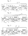
- the process examples shown are followed by a cascade of several mixing vessels 1 to 5 and magnetic separators 6 to 9 , wherein initially the starting medium 10 (aqueous solution) containing a desired target substance, for example a biomolecule (eg a protein) in addition to a variety of undesirable impurities, with the functional magnetic particle 12 and with the surfactant 11 is brought to a solution mixture 13 , the solution by means of a parameter change, in the examples, only the temperature ( T1 and T2 ), between a single-phase and a multi-phase state and switched back and forth after phase separation separated phases can be removed as separate streams.
- the temperature T1 is below in the example, the temperature T2 above the cloud point ( CP value).
- the functional magnetic particles 12 come into contact with the target substance in the solution and bind it selectively and with high affinity.
- all groups known in organic product processing can be used such as ion-exchange active molecules, hydrophobic interaction molecules, group-specific ligands such as metal chelators and protein A or specific antibodies.
- Fig.1 shows the basic scheme of a "Smart Magnetic Extraction Process” (SMEP method).
- the aqueous starting solution 10 is introduced together with functional magnetic particles 12 and with the surfactant 11 in a first mixing chamber 1 and tempered there to a temperature T1 , forming a single-phase aqueous surfactant solution.
- the functional magnetic particles have an affinity for the target substance to be separated and bind it to itself.
- the mixing of the functional magnetic particles 12 and the surfactant 11 into the starting solution takes place simultaneously (in parallel) or behind one another (serial) in the context of the invention.
- mixing in the magnetic particles first and then mixing in the surfactant generally leads to a faster binding of the target substance to the magnetic particles, since interference with the binding of the target substance to the particles is precluded by the surfactant displacing the target substance before the surfactant is mixed in, in particular if the Surfactant attaches itself to the particles.
- the single-phase aqueous surfactant solution is then removed from the first mixing chamber 1 as a solution mixture 13 , heated to the temperature T2 above the cloud point and thus transferred into a two-phase state into a first magnetic separator 6 .
- the parameter used to set the one- or two-phase state of the ATPS in this example is the temperature, although other operating parameters such as ionic strength or pH are also conceivable.
- the functional magnetic particles loaded with the target substance are quantitatively converted into the surfactant-rich (polymer-rich), disperse phase. Unbound biomolecules as well as solid substances By contrast, cell debris, for example, remain in the homogeneous second phase depleted in surfactants (or PFPs ). Due to the magnetic properties of the functional magnetic particles, the phase separation beginning after the temperature increase can be greatly accelerated by a superimposed magnetic field acting on the magnetic particles (illustrated by a permanent magnet) in the first magnetic separator 6 with permanent magnets 14 or equivalent magnetic field sources.
- phase containing the impurities is removed as waste stream 15 and the particles containing surfactant-containing phase 16 is cooled again below the cloud point to the temperature T1 and fed to a second mixing chamber 2 .
- an admixture of a substance takes place in the single-phase phase which, as an aqueous elution buffer 17, causes a detachment of the bound target substance from the functional magnetic particles.
- the target substance leaves in mixture 18 the second mixing chamber in unbound, dissolved form.
- the mixture 18 is reheated to a temperature T3 above the cloud point of the mixture and slid into a second magnetic separator 7 with permanent magments 14 .
- the mixture introduced into the second magnetic separator 7 is thus in a two-phase state, one phase containing the target substance and the other phase containing the magnetic particles.
- the functional magnetic particles go back into the polymer-rich, disperse phase.
- the target substance is now in dissolved free form, it is displaced from the polymer-rich phase and accumulates completely in the polymer-depleted phase.
- the target molecule can be withdrawn as a product via the polymer-poor phase.
- the product is present in solids-free, purified form. While the phase with the functional magnetic particles 12 as Pumblerezykli réelle 19 the first mixing chamber is supplied, there is a derivation of the phase with the dissolved isolated target substance solution 20 to a use not shown.
- the eluted functional magnetic particles as well as the majority of the surfactant can in principle be recycled within the process. Ideally, the eluent is excluded from the polymer-rich phase and direct recycling is possible.
- Fig.2 on the other hand represents a method example, which is characterized on the one hand by a separate return of the functional magnetic particles ( FMP ) and the surfactant in the first mixing chamber 1, on the other hand, for separating the functional magnetic particles 12 from a homogeneous phase in each case on Hochgradientenmagnetseparatoren 8, 9 .
- the surfactant 11 is first separated from the particles and recycled into the first mixing chamber 1 .
- the retained particles with the target substance are forwarded into the mixing chamber 3 .
- the first Hochgradientenmagnetseparator is operated cyclically, ie in a first sub-step, the cleavage of the surfactant, while in a second sub-step, the particles held in Hochgradientenmagentseparator particles are washed out with an elution buffer 17 of these.
- the elution buffer then passes with the particles into the third mixing chamber 3 , in that the actual solution of the target substance takes place from the particles.
- the separation of the magnetic particles then takes place in a second high-gradient magnetic separator 9 .
- the recycled functional magnetic particles 12 and the recycled surfactants 11 are respectively introduced into the first stirring vessel, ie, they are mixed together in the aqueous solution with the target substance (starting solution 10 ).
- the mixing takes place at a temperature T1 below the cloud point of the resulting single-phase aqueous surfactant solution. It is also warmed up to T2 via the cloud point, ie introduced into a first magnetic separator 6 in the two-phase state and split there into a wastewater stream 15 and the surfactant-containing second phase 16 under the action of a magnetic field (permanent magnet 14 or equivalent magnetic source).
- a magnetic field permanent magnet 14 or equivalent magnetic source
- the surfactant-containing second phase 16 is mixed with an aqueous elution buffer 17 only after a separation of the surfactants contained in this contained in solution.
- the separation preferably takes place before renewed cooling of the particle-containing and surfactant-containing phase in a first high-gradient magnetic separator 8 . While the surfactants separated therein are recycled directly into the first mixing chamber, the magnetic particles with the target substance and an elution buffer 17 are introduced into a third mixing chamber 3.
- a modification of the experimental example is according to Fig.2 advantageous in which the separate recycling and mixing of the surfactants 11 ( PFP ) and the functional magnetic particles 12 ( FMP ) is also used in the binding step (see. Figure 3 ).
- the starting solution 10 in a fourth mixing chamber 4 is initially mixed only with the functional magnetic particles 12 to form an aqueous solution, so that the binding can take place undisturbed by possible influences of the surfactants.
- the surfactants 11 (or PFP ) are added thereto .
- the further course of the process corresponds to that in Fig.2 illustrated sequence.
Landscapes
- Health & Medical Sciences (AREA)
- Chemical & Material Sciences (AREA)
- Immunology (AREA)
- Life Sciences & Earth Sciences (AREA)
- Engineering & Computer Science (AREA)
- Urology & Nephrology (AREA)
- Molecular Biology (AREA)
- Biomedical Technology (AREA)
- Chemical Kinetics & Catalysis (AREA)
- Hematology (AREA)
- Medicinal Chemistry (AREA)
- Biochemistry (AREA)
- Cell Biology (AREA)
- Food Science & Technology (AREA)
- Biotechnology (AREA)
- Physics & Mathematics (AREA)
- Analytical Chemistry (AREA)
- Microbiology (AREA)
- General Health & Medical Sciences (AREA)
- General Physics & Mathematics (AREA)
- Pathology (AREA)
- Immobilizing And Processing Of Enzymes And Microorganisms (AREA)
- Extraction Or Liquid Replacement (AREA)
- Peptides Or Proteins (AREA)
Description
- Die Erfindung betrifft ein Verfahren zur magnetisch unterstützen Extraktion gemäß des ersten Patentanspruchs.
- Eine Extraktion der eingangs genannten Art ist ein physikalisches Stofftrennverfahren, bei dem mit Hilfe eines Extraktionsmittels eine Komponente aus einem Stoffgemisch herausgelöst und separiert wird. Das Extraktionsmittel wird dann nach der Separierung wieder entfernt. Extraktionen finden ihre besondere Bedeutung in der Aufbereitung biologischer und biochemischer Substanzen, und zwar sowohl zur Gewinnung als auch zur Aufreinigung dieser Substanzen.
- Hierfür beispielhaft offenbaren [1-5] Verfahren zur Extraktion von Vitamin A und D aus Fischölen oder die Extraktion von Benzylpenizillin aus einer zuvor filtrierten Fermentationsbrühe. Aufgrund der Sensitivität komplexerer Biomoleküle gegenüber unpolaren Lösungsmittel wurden sog. ATPS-Verfahren (ATPS = Aqueous Two Phase Systems) entwickelt (vgl. [3-5]). ATPS sind wässrige Lösungen verschiedener hydrophiler Polymere (z.B. Polyetyhlenglykol (PEG), Dextran) oder von einem Polymer und anorganischen Salzen (z.B. Ammoniumsulfat, Kaliumphosphat). Oberhalb kritischer Konzentrationen dieser Komponenten setzt eine Trennung der Lösung in zwei, je mit einer der Komponenten angereicherten, Phasen ein, in denen Proteine ohne Denaturierung löslich sind [2]. Wird nun eine Biosuspension in ein ATPS überführt, reichern sich ihre Bestandteile entsprechend der jeweiligen Verteilungskoeffizienten in einer der beiden Phasen an. So finden sich im Falle eines PEG-Dextran Systems die Zelltrümmer eines Fermentationshomogenisats in der Regel überwiegend in der Dextranphase während die Proteine überwiegend in die wässrige PEG-Phase übergehen.
- Ein Problem der ATPS sind dabei häufig unzureichende Verteilungskoeffizienten, die eine zeit- und apparatetechnisch aufwendige mehrstufige Verfahrensweise notwendig machen. Um die Selektivität dieses Trennverfahrens zu steigern, werden daher die phasenbildenden Polymere z.B. mit affinen Liganden gezielt funktionalisiert. Damit wirken diese spezifisch auf ein bestimmtes Zielmolekül bzw. eine Gruppe von Zielmolekülen ein und binden diese selektiv an sich an. Ein weiteres grundsätzliches Problem ist die aufgrund des wässrigen Charakters beider Phasen sehr geringe Oberflächenspannung an den Phasengrenzflächen. Folglich besteht nur ein geringes Bestreben des Systems zur Verringerung der Grenzflächen und damit zur Koaleszenz, d.h. die durch Vermischung gebildeten Emulsionen entmischen sich nur sehr langsam. Als Ausweg werden oftmals Zentrifugationsprozesse eingesetzt, die jedoch apparativ aufwendig und damit kostenintensiv sind und zudem in ihrem Durchsatz begrenzt sind. Außerdem entstehen bei einer Trennung insbesondere im Rahmen einer großtechnischen industriellen Nutzung zunächst große Mengen stark polymerhaltiger bzw. stark salzhaltiger Abwässer. Neben den resultierenden Chemikalienkosten spielen folglich auch die Kosten für die Abwasserbehandlung eine Rolle. Folglich strebt man die Umsetzung von ATPS-Verfahren an, die ein Recycling mindestens einer der beteiligten Phasen ermöglichen.
- In [6-8] wird eine Beschleunigung der Phasentrennung von ATPS unter der Zugabe magnetischer Partikel beschrieben. Dabei kamen jedoch stets unfunktionalisierte magnetische Nano- oder Mikropartikel zum Einsatz, so dass die Verteilungskoeffizienten des Systems durch die Beimischung nicht verbessert wurden.
- Folglich kamen in einer späteren Arbeit [9] funktionelle magnetische Partikel in Kombination mit dem ATPS-Verfahren zum Einsatz. Dabei wurden Versuche zur Ermittlung des Verteilungskoeffizienten von Immunglobulinen unter Zugabe von mit Protein A funktionellisierten Magnetpartikeln im kleinen Batch-Maßstab (ca. 1 mL) durchgeführt. Dabei kam ein PEG-Phosphat (ATPS-System) zum Einsatz, wobei der scheinbare Verteilungskoeffizient der PEG-reichen Phase durch die Zugabe der Magnetpartikel je nach Versuchsdurchführung um den Faktor 4-35 gesteigert werden konnte. Der Ansatz verwendet jedoch ein ATPS-System der vorgenannten Art ohne grundsätzliche Änderung, sodass bei einer großtechnischen Umsetzung des Verfahrens nach wie vor mit einer enormen Salzfracht im entstehenden Abwasser zu rechnen ist. Zudem ist die im Falle der Verwendung eines realen Zellhomogenisats resultierende Reinheit nicht besonders hoch, da die PEG-reiche Phase neben der gewünschten Substanz auch zahlreiche andere Proteine an sich bindet.
- Folglich gewinnt beim Versuch eines vollständigen Recyclings der vorgenannten ATPS der Einsatz einer sog. Cloud-Point Extraction (CPE oder CP-ATPS) an Bedeutung. Im Falle der CP-ATPS kommt ein in die Lösung einzumischendes Phase Forming Polymer (Phasenformendes Polymer, PFP), d.h. ein Tensid zum Einsatz. Dieses bewirkt bei Über- oder Unterschreitung einer kritischen Temperatur (Trübungspunkt) oder einer anderen kritischen physikalischen Größe ein Aufspalten einer zunächst homogenen Lösung in zwei makroskopische Phasen, wobei sich das PFP (Tensid) sich nahezu ausschließlich in einer der Phasen anreichert.
- Die Vorteile der CP-ATPS gegenüber klassischen ATPS liegen einerseits in der Zurückgewinnbarkeit der zur Bildung des ATPS herangezogenen Substanz. Andrerseits ermöglichen entsprechende Systeme eine saubere Abtrennung von z.B. Zelltrümmern, da durch die sehr niedrige Grenzflächenspannung zwischen den Phasen die Tendenz zur Feststoffakkumulation an der Phasengrenze nur gering ist. Eine selbst für ATPS geringe Grenzflächenspannung sowie der geringe Dichteunterschied der zu trennenden Phasen bedingt jedoch eine noch schwächere Koaleszenztendenz und sehr langsame und oftmals unvollständige Phasentrennung.
- Davon ausgehend liegt die Aufgabe der Erfindung darin, ein auch im industriellen großtechnischen Maßstab einsetzbares CP-ATPS Verfahren zur magnetisch unterstützen Extraktion vorzuschlagen, das eine effiziente Abtrennung und Vorreinigung von Biomolekülen auch aus fest-stoffhaltigen Medien erlaubt und insbesondere eine signifikant verbesserte Rezyklierbarkeit der Systemkomponenten bei gleichzeitig verbesserter selektiven Abtrennungsleistung in nur einem Verfahrensschritt ermöglicht.
- Die Aufgabe wird durch ein Verfahren mit den Merkmalen des Anspruchs 1 gelöst. Auf diesen rückbezogene Unteransprüche geben vorteilhafte Ausgestaltungen des Verfahrens wieder.
- Die Aufgabe wird mit einem Verfahren zur magnetisch unterstützen Extraktion einer Zielsubstanz aus einer wässrigen Lösung mit mehreren Substanzen, dem sog. SMEP-Verfahren (SMEP = Smart Magnetic Extraction Phases) gelöst. Bei diesem Verfahren erfolgt ein Einmischen von funktionellen magnetischen Partikeln mit einer Affinität zu der gewünschten Zielsubstanz in die wässrige Lösung mit der zu extrahierenden Zielsubstanz (Ausgangslösung), wobei die Zielsubstanz sich an die Partikel vorzugsweise chemisch oder adhäsiv anbindet. Wesentlich ist auch eine vorzugsweise darauf folgende Eingabe eines PFP, vorzugsweise eines Tensids in die wässrige Lösung mit den magnetischen Partikeln, wobei die entstehende Lösung einen Trübungspunkt (CP-Punkt, CP = Cloud-Point) aufweist.
- Wird der Trübungspunkt, d.h. der CP-Punkt überschritten, erfolgt je nach Richtung der Überschreitung eine Überführung der Lösung oder Teile dieser von einem einphasigen in einen zweiphasigen Zustand oder umgekehrt. Der Trübungspunkt wird üblicherweise durch eine bestimmte Temperatur, der Trübungstemperatur wiedergegeben, wobei sich in der Regel bei Temperaturen unterhalb dieser der einphasige Zustand und oberhalb dieser der zweiphasige (bei disperser Durchmischung trübe) Zustand einstellt. Der Trübungspunkt wird wesentlich von der Zusammensetzung der Lösung, insbesondere der Konzentration des PFP oder Tensids in der Lösung beeinflusst.
- Es liegt im Rahmen der Erfindung, wenn der Trübungspunkt auch durch andere Größen bestimmt wird. Anstelle oder in Kombination eines Temperaturwerts ist der Trübungspunkt auch durch einen pH-Wert, eine Ionenstärke oder einer Kombination aus mehreren Größen definierbar, wobei die vorgenannte Phasenänderung durch eine Änderung des pH-Wertes oder auch der Ionenstärke steuerbar ist.
- Im vorliegenden Verfahrensschritt bildet sich bei der vorgenanten Eingabe des PFP oder Tensids zunächst eine einphasige wässrige Tensidlösung (oder PFP-Lösung, im Folgenden pauschal Tensidlösung genannt) aus, die anschließend nach optionalen zusätzlichen Homogenisierungsschritten in vorgenannter Weise in einen zweiphasigen Zustand überführt wird. Dabei entsteht beginnend an den Partikeln mit der angebundenen Zielsubstanz eine erste tensidhaltige (bzw. (PFP-haltige) disperse Phase in einer dieser umgebenden zweiten Phase. Dabei weist die tensidhaltige Phase (PFP-haltige Phase) im Vergleich zur zweiten Phase ein geringeres Aufnahmevermögen für alle nicht an die Partikel gebundenen oder zumindest die von der Zielsubstanz zu separierenden Substanzen auf. Lediglich die zu separierende Zielsubstanz wird durch die funktionellen Magnetpartikel gebunden und somit mit diesen in der tensidhaltigen Phase (PFP-haltige Phase) gehalten.
- In einem weiteren Verfahrensschritt erfolgt eine Separierung der Phasen im Zweiphasengebiet durch Einwirken eines Magnetfeldes. Magnetische Kräfte wirken selektiv auf die magnetischen Partikel ein und ziehen diese gemeinsam mit der angebundenen Zielsubstanz und der tensid- oder PFP-haltigen Phase in Richtung höherer magnetischer Feldstärken. Die koaleszierte tensidhaltige Phase ist dann an dieser Stelle gemeinsam mit den magnetischen Partikel und der Zielsubstanz für eine weitere Verarbeitung von der zweiten Phase beispielsweise durch Absaugung abtrennbar.
- Die Verwendung eines Tensids (oder eines PFP) mit den genannten Eigenschaften (weitgehender Ausschluss aller relevanten Substanzen) wird erst in Kombination mit funktionellen magnetischen Partikeln sinnvoll, bietet dann aber verschiedene Vorteile. Ohne die Verwendung von Nano- oder Mikropartikeln, die die Zielsubstanz binden und im gebundenen Zustand in die disperse Phase überführen, wäre dagegen der Einsatz eines ATPS bei dem eine Phase alle Biomoleküle praktisch ausschließt für die Bioseparation nutzlos, da keine Stofftrennung stattfindet. Umgekehrt ist aber auch der Einsatz der Nano- und Mikropartikel zusammen mit einem ATPS dessen disperse Phase Biomoleküle praktisch ausschließt nur in Kombination mit einem CP-ATPS besonders vorteilhaft, das reversibel zwischen einem einphasigen und einen zweiphasigen Zustand durch die Veränderung eines Parameters geschaltet werden kann. Im Falle eines herkömmlichen ATPS, das ständig im zweiphasigen Zustand vorliegt, würden die Partikel dagegen permanent von der polymerreichen, die Zielsubstanz ausschließenden, Phase umhüllt.
- Eine Anbindung der Zielsubstanz an die Partikel und damit die angestrebte Stofftrennung wäre daher nicht möglich.
- Die Erfindung wird anhand von Versuchsbeispielen mit den folgenden Figuren näher erläutert, wobei der Begriff Tensid grundsätzlich eine alternative Verwendung von PFP mit einschließt. Es zeigen
-
Fig.1 das Grundablaufschema eines SMEP-Verfahrensbeispiels, -
Fig.2 ein Ablaufschema eines SMEP-Verfahrensbeispiels mit einer getrennten Rückführung der funktionellen Magnetpartikel (FMP) und des Tensids sowie -
Fig.3 ein Ablaufschema des SMEP-Verfahrens gemäßFig.2 , jedoch mit einer zeitversetzten separaten Einspeisung der rückgeführten funktionellen Magnetpartikel und der Tenside. - Bei allen in den
Fig.1 bis 3 dargestellten Verfahrensbeispielen wird eine Kaskade von mehreren Mischgefäßen 1 bis 5 und magnetischen Separatoren 6 bis 9 durchfahren, wobei zunächst das Ausgangsmedium 10 (wässrige Lösung), das eine gewünschte Zielsubstanz, beispielsweise ein Biomolekül (z.B. ein Protein) neben einer Vielzahl unerwünschter Begleitstoffe enthält, mit den funktionellen Magnetpartikel 12 und mit dem Tensid 11 zu einem Lösungsgemisch 13 zusammengebracht wird, die Lösung mittels eines Parameterwechsels, in den Beispielen nur die Temperatur (T1 und T2), zwischen einem einphasigen und einem mehrphasigen Zustand hin- und hergeschaltet wird und nach Phasentrennung die getrennten Phasen als separate Stoffströme entnehmbar sind. Die Temperatur T1 liegt im Beispiel dabei unterhalb, die Temperatur T2 dabei oberhalb des Trübungspunktes (CP-Wert). - Die funktionellen Magnetpartikel 12 kommen in der Lösung mit der Zielsubstanz in Kontakt und binden diese selektiv und mit hoher Affinität. Als Funktionalisierung der funktionellen Magnetpartikel können dabei alle in der Bioproduktaufarbeitung bekannten Gruppen benutzt werden, wie z.B. ionenaustauschaktive Moleküle, Moleküle mit hydrophober Wechselwirkung, gruppenspezifische Liganden wie Metallchelatbildner und Protein A oder spezifische Antikörper.
-
Fig.1 zeigt das Grundschema eines "Smart Magnetic Extraction Process" (SMEP-Verfahren). Die wässrige Ausgangslösung 10 wird gemeinsam mit funktionellen Magnetpartikeln 12 und mit dem Tensid 11 in einer ersten Mischkammer 1 eingegeben und dort auf eine Temperatur T1 temperiert, wobei sich eine einphasige wässrige Tensidlösung bildet. Die funktionellen magnetischen Partikel weisen dabei eine Affinität zu der zu separierenden Zielsubstanz auf und binden diese an sich. - Das Einmischen der funktionellen Magnetpartikel 12 und des Tensid 11 in die Ausgangslösung erfolgt im Rahmen der Erfindung zeitgleich (parallel) oder hintereinander (seriell). Ein Einmischen zunächst der Magnetpartikel und anschließenden Einmischen des Tensids führt jedoch grundsätzlich zu einer schnellere Anbindung der Zielsubstanz an die magnetischen Partikel, da vor einmischen des Tensids eine Behinderung der Anbindung der Zielsubstanz an die Partikel durch das die Zielsubstanz verdrängende Tensid ausgeschlossen wird, insbesondere wenn das Tensid sich selbst an den Partikeln anlagert.
- Die einphasige wässrige Tensidlösung wird anschließend als Lösungsgemisch 13 aus der ersten Mischkammer 1 entnommen, auf die Temperatur T2 oberhalb des Trübungspunktes erwärmt und auf diese Weise in einen zweiphasigen Zustand überführt in einen ersten magnetischen Separator 6 eingeleitet.
- Der zum Einstellen des ein- oder zweiphasigen Zustands des ATPS benutzte Parameter ist in diesem Beispiel die Temperatur, wobei auch andere Betriebsparameter wie z.B. Ionenstärke oder pH-Wert denkbar sind.
- Die mit der Zielsubstanz beladenen funktionellen Magnetpartikel gehen dabei nach Voraussetzung quantitativ in die tensidreiche (polymerreiche), disperse Phase über. Ungebundene Biomoleküle sowie Fest-Stoffe wie z.B. Zelltrümmer verbleiben dagegen in der homogenen, an Tensiden (bzw. PFP) abgereicherten zweiten Phase. Aufgrund der magnetischen Eigenschaften der funktionellen Magnetpartikel lässt sich die nach der Temperaturerhöhung einsetzende Phasentrennung durch ein überlagertes und auf die magnetischen Partikel einwirkendes Magnetfeld (illustriert durch einen Permanentmagneten) in dem ersten magnetischen Separator 6 mit Permanentmagneten 14 oder gleich wirkenden Magnetfeldquellen stark beschleunigen.
- Nach Abschluss der Phasentrennung wird die die Verunreinigungen enthaltende Phase als Abwasserstrom 15 abgeführt und die die Partikel enthaltende tensidhaltige Phase 16 wieder unter den Trübungspunkt auf die Temperatur T1 abgekühlt und einer zweiten Mischkammer 2 zugeführt.
- In der zweiten Mischkammer 2 erfolgt eine Einmischung einer Substanz in die einphasig vorliegende Phase, die als wässriger Elutionspuffer 17 eine Ablösung der gebundenen Zielsubstanz von den funktionellen Magnetpartikeln bewirkt. Am Ende dieses Verfahrensschritts verlässt die Zielsubstanz im Gemisch 18 die zweite Mischkammer in ungebundener gelöster Form. Danach wird das Gemisch 18 erneut auf eine Temperatur T3 oberhalb des Trübungspunktes des Gemischs aufgewärmt und in einen zweiten magnetischen Separator 7 mit Permanentmagenten 14 gleitet.
- Das in den zweiten magnetischen Separator 7 eingeleitete Gemisch liegt somit in einem zweiphasigen Zustand vor, wobei eine Phase die Zielsubstanz und die andere Phase die magnetischen Partikel beinhaltet. Die funktionellen Magnetpartikel gehen dabei wieder in die polymerreiche, disperse Phase über. Da die Zielsubstanz nun aber in gelöster freier Form vorliegt, wird sie aus der polymerreichen Phase verdrängt und reichert sich komplett in der an Polymer abgereicherten Phase an. Nach einer wiederum durch ein überlagertes Magnetfeld beschleunigten Phasentrennung, kann das Zielmolekül als Produkt über die polymerarme Phase abgezogen werden. Das Produkt liegt dabei in feststofffreier, aufgereinigter Form vor. Während die Phase mit den funktionellen magnetischen Partikeln 12 als Partikelrezyklierung 19 der ersten Mischkammer zugeführt wird, erfolgt eine Ableitung der Phase mit der gelösten isolierten Zielsubstanzlösung 20 zu einer nicht weiter dargestellten Verwendung.
- Die eluierten funktionellen Magnetpartikel sowie der Großteil des Tensids können grundsätzlich innerhalb des Prozesses rezykliert werden. Im Idealfall wird auch das Elutionsmittel aus der polymerreichen Phase ausgeschlossen und eine direkte Rückführung ist möglich.
-
Fig.2 repräsentiert dagegen ein Verfahrensbeispiel, das sich einerseits durch eine getrennte Rückführung der funktionellen Magnetpartikel (FMP) und des Tensids in die erste Mischkammer 1 kennzeichnet, andererseits zur Abtrennung der funktionellen Magnetpartikel 12 aus einer homogenen Phase jeweils auf Hochgradientenmagnetseparatoren 8, 9 zurückgreift. - Dabei wird in dem ersten Hochgradientenmagnetseparator 8 zunächst das Tensid 11 von den Partikeln getrennt und in das erste Mischkammer 1 rezykliert. Die zurückgehaltenen Partikel mit der Zielsubstanz werden in die Mischkammer 3 weitergeleitet. Vorzugsweise wird der erste Hochgradientenmagnetseparator dabei zyklisch betrieben, d.h. in einem ersten Teilschritt erfolgt die Abspaltung des Tensids, während in einem zweiten Teilschritt die im Hochgradientenmagentseparator festgehaltenen Partikel mit einen Elutionspuffer 17 aus diesen herausgespült werden.
- Der Elutionspuffer gelangt mit den Partikeln anschließend in die dritte Mischkammer 3, indem die eigentliche Lösung der Zielsubstanz von den Partikeln erfolgt. Die Abtrennung der Magnetpartikel erfolgt dann anschließend in einem zweiten Hochgradientenmagnetseparator 9.
- Die rezyklierten funktionellen Magnetpartikel 12 und die rezyklierten Tenside 11 werden jeweils in das erste Rührgefäß eingeleitet, d.h. es erfolgt eine gemeinsame Einmischung dieser in die wässrige Lösung mit der Zielsubstanz (Ausgangslösung 10).
- Wie im vorgenannten und in
Fig.1 dargestellten Verfahrensbeispiel erfolgt die Einmischung mit einer Temperatur T1 unterhalb des Trübungspunkts der entstandenen einphasigen wässrigen Tensidlösung. Ebenso wird diese über den Trübungspunkt auf T2 aufgewärmt, d.h. im zweiphasigen Zustand in einen ersten magnetischen Separator 6 eingeleitet und dort unter Einwirkung eines Magnetfeldes (Permanentmagnet 14 oder gleich wirkende Magnetquelle) in einen Abwasserstrom 15 und der tensidhaltigen zweiten Phase 16 aufgeteilt. - Abweichend von dem erstgenannten Versuchsbeispiel (vgl.
Fig.1 ) wird die tensidhaltige zweite Phase 16 erst nach einer Abtrennung der in dieser enthaltenen in Lösung befindlichen Tenside mit einem wässrigen Elutionspuffer 17 vermischt. Die Abrennung erfolgt vorzugsweise vor einer erneuten Abkühlung der partikel- und tensidhaltigen Phase in einem ersten Hochgradientenmagnetseparator 8. Während die darin abgetrennten Tenside direkt in die erste Mischkammer rzykliert werden, werden die magnetischen Partikel mit der Zielsubstanz sowie ein Elutionspuffer 17 in eine dritten Mischkammer 3 eingeleitet. - Schließlich ist auch der Fall denkbar, dass die eingesetzten Tenside im Einphasengebiet einen negativen Einfluss auf die Anbindung der Zielmoleküle an die funktionellen Magnetpartikel ausüben. In diesem Fall ist eine Abwandlung des Versuchsbeispiels gemäß
Fig.2 vorteilhaft, in der die getrennte Rückführung und Einmischung der Tenside 11 (PFP) und der funktionellen Magnetpartikel 12 (FMP) auch im Bindeschritt genutzt wird (vgl.Fig.3 ). Dabei wird in einem ersten Schritt die Ausgangslösung 10 in einer vierten Mischkammer 4 zunächst nur mit den funktionellen Magnetpartikeln 12 zu einer wässrigen Lösung vermischt, so dass die Bindung ungestört von möglichen Einflüssen der Tenside stattfinden kann. Anschließend erfolgt nach Weiterleitung der wässrigen Lösung in eine fünfte Mischkammer 5 in dieser die Zugabe der Tenside 11 (bzw. PFP). Der weitere Prozessverlauf entspricht der inFig.2 dargestellten Abfolge. -
- [1] Ullmanns Encyclopedia of Technical Chemistry, Vol. B3, Chapter 6: Liquid-Liquid Extraction,
- [2] Ullmanns Encyclopedia of Technical Chemistry, Vol. B3, Chapter 11: Biochemical Separations,
- [3] Albertsson, P .A.: Partition of Cell Particles and Macromolecules, New York: Wiley (1986)
- [4] Johansson, G.: Aqueous two-phase systems in protein purification, J. Biotech. 3 (1985) 11-18
- [5] Scopes, R.K.: Protein purification in the nineties; Biotechnol. Appl, Biochem., 23 (1996) 197-204
- [6] Wikström, P. et al.: Magnetic aqueous two-phase separation: A new technique to increase rate of phase-separation, using dextran-ferrofluidor larger iron oxide particles. Anal. Biochem. (1987) 167: 331-339.
- [7] Wikström, P. et al.: Magnetically enhanced aqueous two-phase separation, in Separation using aqueous phase systems, D. Fisher and I.A. Sutherland, Editors. (1989) Plenum Publishing Corp. 455-461
- [8] Flygare, S. et al.: Magnetic aqueous two-phase Separation in preperative applications, Enzyme Microb. Tech., 12 (1990) 95-103
- [9] Suzuki, M. et al.: Affinity Partitioning of Protein A using a Magnetic Aqueous Two-Phase System, J. Ferment. Bioeng. 80 (1995) 78-84
- [10] Franzreb, M. et al.: Product recovery by high-gradient magnetic fishing (HGMF), in PROCESS SCALE BIOSEPARATIONS FOR THE BIOPHARMACEUTICAL INDUSTRY, Eds. Shukla, A.; Etzel, M. and Gadam, S., CRC Press (2006) ISBN 1-57444-517-0
SAITOH T. and HINZE W. L.: "USE OF SURFACTANT-MEDIATED PHASE SEPARATION (CLOUD POINT EXTRACTION) WITH AFFINITY LIGANDS FOR THE EXTRACTION OF HYDROPHILIC PROTEINS", TALANTA, ELMSFORD,NY, US, Bd. 42, Nr. 1, 1. Januar 1995 (1995-01-01), Seiten 119-127
WO 03/089906 A (UNIV FLORIDA [US]) 30. Oktober 2003 (2003-10-30 -
- 1
- Erste Mischkammer
- 2
- zweite Mischkammer
- 3
- dritte Mischkammer
- 4
- vierte Mischkammer
- 5
- fünfte Mischkammer
- 6
- erster Separator
- 7
- zweiter Separator
- 8
- erster Hochgradientenmagentseparator
- 9
- zweiter Hochgradientenmagentseparator
- 10
- Ausgangslösung
- 11
- Tensid
- 12
- Funktionelle Magnetpartikel
- 13
- Wässrige Tensidlösung
- 14
- Permanentmagnet
- 15
- Abwasserstrom
- 16
- Tensidhaltige Phase
- 17
- Elutionspuffer
- 18
- Gemisch
- 19
- Partikelrezyklierung
- 20
- Zielsubstanzlösung
Claims (8)
- Verfahren zur magnetisch unterstützen Extraktion einer Zielsubstanz aus einer wässrigen Lösung mit mehreren Substanzen, umfassend folgende Verfahrensschritte:a) Einmischen von funktionellen magnetischen Partikeln mit einer Affinität zu der Zielsubstanz, wobei die Zielsubstanz sich an die Partikel anbindet, sowie eines Tensids in die wässrige Lösung mit den magnetischen Partikeln, wobei sich eine partikelhaltige einphasige wässrige Tensidlösung ausbildet,b) Überführung der Tensidlösung in einen zweiphasigen Zustand, wobei eine erste partikel- und tensidhaltige disperse Phase in einer diese umgebenden zweiten Phase entsteht, wobei die tensidhaltige Phase ein geringeres Aufnahmevermögen für ungebundene gelöste Substanzen in der Lösung aufweist als die zweite Phase,c) Separierung der Phasen im Zweiphasengebiet durch Einwirken eines Magnetfeldes sowied) Abtrennung der tensidhaltigen Phase mit den magnetischen Partikeln mit der Zielsubstanz.
- Verfahren nach Anspruch 1, umfassend die weitern nachfolgenden Verfahrensschritte:a) Zugabe eines wässrigen Elutionspuffers in die tensidhaltige Phase unter Bildung eines Gemischs,b) Überführung des Gemischs in einen einphasigen Zustand, wobei die Zielsubstanz von den magnetischen Partikeln gelöst wird,c) Erneute Überführung der einphasigen Lösung in einen zweiphasigen Zustand, wobei eine Phase die Zielsubstanz und die andere Phase die magnetischen Partikel enthält sowied) Separierung der Phasen durch Einwirken eines Magnetfeldes.
- Verfahren nach Anspruch 2, umfassend eine parallele Einmischung von magnetischen Partikeln und tensidhaltiger Phase in die wässrige Lösung mit der Zielsubstanz.
- Verfahren nach Anspruch 2, umfassend eine serielle Einmischung von magnetischen Partikeln und anschließend der Tenside in die wässrige Lösung mit der Zielsubstanz.
- Verfahren nach einem der vorgenannten Ansprüche, dadurch gekennzeichnet, dass nach der Abtrennung der ersten tensidhaltigen Phase mit den magnetischen Partikeln mit der Zielsubstanz eine weitere magnetische Abtrennung der magnetischen Partikel mit der Zielsubstanz aus der tensidhaltigen Phase erfolgt.
- Verfahren nach einem der vorgenannten Ansprüche 1 bis 5, dadurch gekennzeichnet, dass die Überführung der Lösung in einen ein- oder zweiphasigen Zustand mittels eines Temperaturwechsels erfolgt.
- Verfahren nach einem der vorgenannten Ansprüche 1 bis 5, dadurch gekennzeichnet, dass die Überführung der Lösung in einen ein- oder zweiphasigen Zustand mittels einer Änderung des pH-Wertes in der Lösung erfolgt.
- Verfahren nach einem der vorgenannten Ansprüche 1 bis 5, dadurch gekennzeichnet, dass die Überführung der Lösung in einen ein- oder zweiphasigen Zustand mittels eines Ionenstärkewechsels erfolgt.
Applications Claiming Priority (2)
| Application Number | Priority Date | Filing Date | Title |
|---|---|---|---|
| DE102007020220A DE102007020220B3 (de) | 2007-04-28 | 2007-04-28 | Verfahren zur magnetisch unterstützten Extraktion |
| PCT/EP2008/003245 WO2008131891A1 (de) | 2007-04-28 | 2008-04-23 | Verfahren zur magnetisch unterstützten extraktion |
Publications (2)
| Publication Number | Publication Date |
|---|---|
| EP2142271A1 EP2142271A1 (de) | 2010-01-13 |
| EP2142271B1 true EP2142271B1 (de) | 2016-10-05 |
Family
ID=39641933
Family Applications (1)
| Application Number | Title | Priority Date | Filing Date |
|---|---|---|---|
| EP08749051.2A Not-in-force EP2142271B1 (de) | 2007-04-28 | 2008-04-23 | Verfahren zur magnetisch unterstützten extraktion |
Country Status (4)
| Country | Link |
|---|---|
| US (1) | US8158007B2 (de) |
| EP (1) | EP2142271B1 (de) |
| DE (1) | DE102007020220B3 (de) |
| WO (1) | WO2008131891A1 (de) |
Families Citing this family (13)
| Publication number | Priority date | Publication date | Assignee | Title |
|---|---|---|---|---|
| PL2313200T3 (pl) * | 2008-07-18 | 2012-11-30 | Basf Se | Cząstki nieorganiczne z powłoką organiczną o właściwościach hydrofilowych/hydrofobowych, które mogą ulegać zmianie pod wpływem temperatury |
| US8192630B1 (en) | 2010-12-21 | 2012-06-05 | Empire Technology Development Llc | Magnetic in-line purification of fluid |
| GB201301631D0 (en) | 2013-01-30 | 2013-03-13 | Ge Healthcare Ltd | Separation of substances using magnetic beads |
| CN105188944B (zh) * | 2013-03-15 | 2017-10-27 | 凯斯西储大学 | 从溶液中除去金属的系统和方法 |
| US11684995B2 (en) | 2013-11-13 | 2023-06-27 | Hypertherm, Inc. | Cost effective cartridge for a plasma arc torch |
| PT107379A (pt) | 2013-12-23 | 2015-10-13 | Faculdade De Ciências E Tecnologia Da Universidade Nova De Lisboa | Extração líquido-líquido magnética para a purificação e separação de substâncias |
| CN107635666B (zh) * | 2015-04-03 | 2020-10-02 | 卢卡·贝廷索利 | 用于通过磁性纳米颗粒分离的装置和方法 |
| EP3864128A4 (de) | 2018-10-10 | 2022-07-06 | Stamm Vegh Corporation | Mikrobioreaktor mit kontinuierlichem strom |
| KR102174177B1 (ko) * | 2018-11-19 | 2020-11-05 | 포항공과대학교 산학협력단 | 수용액 이상계 나노필터 및 이를 이용한 분리방법 |
| UY39063A (es) | 2020-02-03 | 2021-08-31 | Stamm Vegh Corp | Plataforma, sistemas y dispositivos para impresiones 3d |
| CN114053755B (zh) * | 2020-08-07 | 2023-04-11 | 中国石油化工股份有限公司 | 一种用于内墙涂料有害物质检测的萃取剂及萃取方法 |
| AU2023374883A1 (en) | 2022-11-02 | 2025-05-22 | Phase Scientific International, Ltd. | Methods for isolating target analytes from biological samples using atps and solid phase media |
| WO2024243043A2 (en) * | 2023-05-19 | 2024-11-28 | Stamm Vegh Corporation | Continuous purification device |
Family Cites Families (3)
| Publication number | Priority date | Publication date | Assignee | Title |
|---|---|---|---|---|
| FR2773416B1 (fr) * | 1998-01-06 | 2000-02-11 | Bio Merieux | Particules magnetiques perfectionnees, leurs procedes d'obtention et leurs utilisations dans la separation de molecules |
| DE60320780D1 (de) | 2002-04-22 | 2008-06-19 | Univ Florida | Funktionalisierte nanopartikel und verwendungsverfahren |
| DE102005034327B3 (de) * | 2005-07-22 | 2006-11-30 | Forschungszentrum Karlsruhe Gmbh | Vorrichtung zur Affinitätsseparation mittels magnetischer Partikel |
-
2007
- 2007-04-28 DE DE102007020220A patent/DE102007020220B3/de not_active Expired - Fee Related
-
2008
- 2008-04-23 EP EP08749051.2A patent/EP2142271B1/de not_active Not-in-force
- 2008-04-23 WO PCT/EP2008/003245 patent/WO2008131891A1/de not_active Ceased
- 2008-04-23 US US12/597,952 patent/US8158007B2/en not_active Expired - Fee Related
Also Published As
| Publication number | Publication date |
|---|---|
| DE102007020220B3 (de) | 2008-11-13 |
| WO2008131891A1 (de) | 2008-11-06 |
| US20100116747A1 (en) | 2010-05-13 |
| US8158007B2 (en) | 2012-04-17 |
| EP2142271A1 (de) | 2010-01-13 |
Similar Documents
| Publication | Publication Date | Title |
|---|---|---|
| DE102007020220B3 (de) | Verfahren zur magnetisch unterstützten Extraktion | |
| DE69033304T2 (de) | Verfahren und Montur für die Reinigung von Nukleinsäuren | |
| DE69109275T2 (de) | Verfahren zur isolierung von makromolekülen mittels magnetisch anziehbarer kugeln, die die makromoleküle unspezifisch binden. | |
| DE69828517T2 (de) | Methode zur dns-isolierung. | |
| DE69734263T2 (de) | Verfahren zur Isolierung von Ribonucleinsäuren. | |
| DE69936584T2 (de) | Schnelles und einfaches verfahren zur isolierung von zirkulären nukleinsäuren | |
| DE112010001766B4 (de) | Verfahren zur isolierung hochreiner rna mittels paramagnetischen mikro- und nanopartikeln | |
| DE19746874A1 (de) | Verfahren zur Isolierung und Reinigung von Nukleinsäuren an hydrophoben Oberflächen - insbesondere unter Verwendung hydrophober Membranen | |
| WO2008145587A1 (de) | Verfahren zur schonenden zellaufreinigung, zellgewinnung und transfektion von zellen | |
| DE69428356T2 (de) | Reinigung von plasmaproteinen | |
| WO2016169679A1 (de) | Vorrichtung und verfahren zur automatisierten extraktion von nukleinsäuren | |
| EP3596215A1 (de) | Verfahren zur anreicherung von zellen aus einer probe und der nachfolgenden nukleinsäureisolierung aus diesen zellen | |
| EP1274745A1 (de) | Magnetische, silanisierte trägermaterialien auf basis von polyvinylalkohol | |
| EP1960520A1 (de) | Verfahren zur isolierung von nukleinsäuren aus beliebigen ausgangsmaterialien | |
| DE69817000T2 (de) | Verfahren zur schnellen isolierung von rns | |
| DE19912799B4 (de) | Superparamagnetisches Adsorptionsmaterial und seine Verwendung | |
| EP2041281B2 (de) | Verfahren zur parallelen isolierung doppel- und einzelsträngiger nukleinsäuren sowie zur selektiven entfernung doppelsträngiger nukleinsäuren aus einem gemisch von doppel- und einzelsträngigen nukleinsäuren | |
| EP1242816A2 (de) | Chromatographiematerial und verfahren unter verwendung desselben | |
| EP1960521A1 (de) | Verfahren und testkit zur trennung, aufreinigung und wiedergewinnung von lang- und kurzkettigen nukleinsäuren | |
| DE10207170A1 (de) | Verfahren zur Grobklärung von Zellaufschlüssen aus Mikroorganismen | |
| EP0726907B1 (de) | Verfahren zur herstellung einer virusinaktivierten faktor viii enthaltenden fraktion mittels chromatographischer methoden | |
| DE10033194C2 (de) | Biosonden und deren Verwendung | |
| DD296261A5 (de) | Verfahren zur biosorption von schwermetallen | |
| EP2274319A2 (de) | Verfahren zur reinigung therapeutischer proteine mittels mehrstufiger extraktion | |
| EP1697540A1 (de) | Verfahren zur anreicherung und stabilisierung von dna-haltigen bestandteilen aus biologischen materialien |
Legal Events
| Date | Code | Title | Description |
|---|---|---|---|
| PUAI | Public reference made under article 153(3) epc to a published international application that has entered the european phase |
Free format text: ORIGINAL CODE: 0009012 |
|
| 17P | Request for examination filed |
Effective date: 20090811 |
|
| AK | Designated contracting states |
Kind code of ref document: A1 Designated state(s): AT BE BG CH CY CZ DE DK EE ES FI FR GB GR HR HU IE IS IT LI LT LU LV MC MT NL NO PL PT RO SE SI SK TR |
|
| DAX | Request for extension of the european patent (deleted) | ||
| GRAP | Despatch of communication of intention to grant a patent |
Free format text: ORIGINAL CODE: EPIDOSNIGR1 |
|
| RIC1 | Information provided on ipc code assigned before grant |
Ipc: G01N 33/543 20060101ALI20160113BHEP Ipc: B03C 1/28 20060101ALI20160113BHEP Ipc: B01D 11/04 20060101AFI20160113BHEP |
|
| INTG | Intention to grant announced |
Effective date: 20160204 |
|
| GRAS | Grant fee paid |
Free format text: ORIGINAL CODE: EPIDOSNIGR3 |
|
| GRAL | Information related to payment of fee for publishing/printing deleted |
Free format text: ORIGINAL CODE: EPIDOSDIGR3 |
|
| GRAS | Grant fee paid |
Free format text: ORIGINAL CODE: EPIDOSNIGR3 |
|
| GRAA | (expected) grant |
Free format text: ORIGINAL CODE: 0009210 |
|
| AK | Designated contracting states |
Kind code of ref document: B1 Designated state(s): AT BE BG CH CY CZ DE DK EE ES FI FR GB GR HR HU IE IS IT LI LT LU LV MC MT NL NO PL PT RO SE SI SK TR |
|
| REG | Reference to a national code |
Ref country code: GB Ref legal event code: FG4D Free format text: NOT ENGLISH |
|
| REG | Reference to a national code |
Ref country code: CH Ref legal event code: EP Ref country code: CH Ref legal event code: NV Representative=s name: ROTTMANN, ZIMMERMANN + PARTNER AG, CH |
|
| REG | Reference to a national code |
Ref country code: AT Ref legal event code: REF Ref document number: 834123 Country of ref document: AT Kind code of ref document: T Effective date: 20161015 |
|
| REG | Reference to a national code |
Ref country code: CH Ref legal event code: PCAR Free format text: NEW ADDRESS: GARTENSTRASSE 28 A, 5400 BADEN (CH) |
|
| REG | Reference to a national code |
Ref country code: IE Ref legal event code: FG4D Free format text: LANGUAGE OF EP DOCUMENT: GERMAN |
|
| REG | Reference to a national code |
Ref country code: DE Ref legal event code: R096 Ref document number: 502008014685 Country of ref document: DE |
|
| REG | Reference to a national code |
Ref country code: NL Ref legal event code: MP Effective date: 20161005 |
|
| REG | Reference to a national code |
Ref country code: LT Ref legal event code: MG4D |
|
| PG25 | Lapsed in a contracting state [announced via postgrant information from national office to epo] |
Ref country code: LV Free format text: LAPSE BECAUSE OF FAILURE TO SUBMIT A TRANSLATION OF THE DESCRIPTION OR TO PAY THE FEE WITHIN THE PRESCRIBED TIME-LIMIT Effective date: 20161005 |
|
| REG | Reference to a national code |
Ref country code: FR Ref legal event code: PLFP Year of fee payment: 10 |
|
| PG25 | Lapsed in a contracting state [announced via postgrant information from national office to epo] |
Ref country code: GR Free format text: LAPSE BECAUSE OF FAILURE TO SUBMIT A TRANSLATION OF THE DESCRIPTION OR TO PAY THE FEE WITHIN THE PRESCRIBED TIME-LIMIT Effective date: 20170106 Ref country code: SE Free format text: LAPSE BECAUSE OF FAILURE TO SUBMIT A TRANSLATION OF THE DESCRIPTION OR TO PAY THE FEE WITHIN THE PRESCRIBED TIME-LIMIT Effective date: 20161005 Ref country code: NO Free format text: LAPSE BECAUSE OF FAILURE TO SUBMIT A TRANSLATION OF THE DESCRIPTION OR TO PAY THE FEE WITHIN THE PRESCRIBED TIME-LIMIT Effective date: 20170105 Ref country code: LT Free format text: LAPSE BECAUSE OF FAILURE TO SUBMIT A TRANSLATION OF THE DESCRIPTION OR TO PAY THE FEE WITHIN THE PRESCRIBED TIME-LIMIT Effective date: 20161005 |
|
| PG25 | Lapsed in a contracting state [announced via postgrant information from national office to epo] |
Ref country code: ES Free format text: LAPSE BECAUSE OF FAILURE TO SUBMIT A TRANSLATION OF THE DESCRIPTION OR TO PAY THE FEE WITHIN THE PRESCRIBED TIME-LIMIT Effective date: 20161005 Ref country code: IS Free format text: LAPSE BECAUSE OF FAILURE TO SUBMIT A TRANSLATION OF THE DESCRIPTION OR TO PAY THE FEE WITHIN THE PRESCRIBED TIME-LIMIT Effective date: 20170205 Ref country code: NL Free format text: LAPSE BECAUSE OF FAILURE TO SUBMIT A TRANSLATION OF THE DESCRIPTION OR TO PAY THE FEE WITHIN THE PRESCRIBED TIME-LIMIT Effective date: 20161005 Ref country code: HR Free format text: LAPSE BECAUSE OF FAILURE TO SUBMIT A TRANSLATION OF THE DESCRIPTION OR TO PAY THE FEE WITHIN THE PRESCRIBED TIME-LIMIT Effective date: 20161005 Ref country code: PL Free format text: LAPSE BECAUSE OF FAILURE TO SUBMIT A TRANSLATION OF THE DESCRIPTION OR TO PAY THE FEE WITHIN THE PRESCRIBED TIME-LIMIT Effective date: 20161005 Ref country code: PT Free format text: LAPSE BECAUSE OF FAILURE TO SUBMIT A TRANSLATION OF THE DESCRIPTION OR TO PAY THE FEE WITHIN THE PRESCRIBED TIME-LIMIT Effective date: 20170206 Ref country code: FI Free format text: LAPSE BECAUSE OF FAILURE TO SUBMIT A TRANSLATION OF THE DESCRIPTION OR TO PAY THE FEE WITHIN THE PRESCRIBED TIME-LIMIT Effective date: 20161005 |
|
| REG | Reference to a national code |
Ref country code: DE Ref legal event code: R097 Ref document number: 502008014685 Country of ref document: DE |
|
| PG25 | Lapsed in a contracting state [announced via postgrant information from national office to epo] |
Ref country code: RO Free format text: LAPSE BECAUSE OF FAILURE TO SUBMIT A TRANSLATION OF THE DESCRIPTION OR TO PAY THE FEE WITHIN THE PRESCRIBED TIME-LIMIT Effective date: 20161005 Ref country code: SK Free format text: LAPSE BECAUSE OF FAILURE TO SUBMIT A TRANSLATION OF THE DESCRIPTION OR TO PAY THE FEE WITHIN THE PRESCRIBED TIME-LIMIT Effective date: 20161005 Ref country code: DK Free format text: LAPSE BECAUSE OF FAILURE TO SUBMIT A TRANSLATION OF THE DESCRIPTION OR TO PAY THE FEE WITHIN THE PRESCRIBED TIME-LIMIT Effective date: 20161005 Ref country code: EE Free format text: LAPSE BECAUSE OF FAILURE TO SUBMIT A TRANSLATION OF THE DESCRIPTION OR TO PAY THE FEE WITHIN THE PRESCRIBED TIME-LIMIT Effective date: 20161005 Ref country code: CZ Free format text: LAPSE BECAUSE OF FAILURE TO SUBMIT A TRANSLATION OF THE DESCRIPTION OR TO PAY THE FEE WITHIN THE PRESCRIBED TIME-LIMIT Effective date: 20161005 |
|
| PLBE | No opposition filed within time limit |
Free format text: ORIGINAL CODE: 0009261 |
|
| STAA | Information on the status of an ep patent application or granted ep patent |
Free format text: STATUS: NO OPPOSITION FILED WITHIN TIME LIMIT |
|
| PG25 | Lapsed in a contracting state [announced via postgrant information from national office to epo] |
Ref country code: BG Free format text: LAPSE BECAUSE OF FAILURE TO SUBMIT A TRANSLATION OF THE DESCRIPTION OR TO PAY THE FEE WITHIN THE PRESCRIBED TIME-LIMIT Effective date: 20170105 Ref country code: IT Free format text: LAPSE BECAUSE OF FAILURE TO SUBMIT A TRANSLATION OF THE DESCRIPTION OR TO PAY THE FEE WITHIN THE PRESCRIBED TIME-LIMIT Effective date: 20161005 |
|
| 26N | No opposition filed |
Effective date: 20170706 |
|
| PG25 | Lapsed in a contracting state [announced via postgrant information from national office to epo] |
Ref country code: SI Free format text: LAPSE BECAUSE OF FAILURE TO SUBMIT A TRANSLATION OF THE DESCRIPTION OR TO PAY THE FEE WITHIN THE PRESCRIBED TIME-LIMIT Effective date: 20161005 |
|
| REG | Reference to a national code |
Ref country code: IE Ref legal event code: MM4A |
|
| PG25 | Lapsed in a contracting state [announced via postgrant information from national office to epo] |
Ref country code: MC Free format text: LAPSE BECAUSE OF FAILURE TO SUBMIT A TRANSLATION OF THE DESCRIPTION OR TO PAY THE FEE WITHIN THE PRESCRIBED TIME-LIMIT Effective date: 20161005 |
|
| PG25 | Lapsed in a contracting state [announced via postgrant information from national office to epo] |
Ref country code: LU Free format text: LAPSE BECAUSE OF NON-PAYMENT OF DUE FEES Effective date: 20170423 |
|
| REG | Reference to a national code |
Ref country code: BE Ref legal event code: MM Effective date: 20170430 |
|
| REG | Reference to a national code |
Ref country code: FR Ref legal event code: PLFP Year of fee payment: 11 |
|
| PG25 | Lapsed in a contracting state [announced via postgrant information from national office to epo] |
Ref country code: IE Free format text: LAPSE BECAUSE OF NON-PAYMENT OF DUE FEES Effective date: 20170423 |
|
| PG25 | Lapsed in a contracting state [announced via postgrant information from national office to epo] |
Ref country code: BE Free format text: LAPSE BECAUSE OF NON-PAYMENT OF DUE FEES Effective date: 20170430 |
|
| PGFP | Annual fee paid to national office [announced via postgrant information from national office to epo] |
Ref country code: CH Payment date: 20180424 Year of fee payment: 11 Ref country code: DE Payment date: 20180423 Year of fee payment: 11 |
|
| PGFP | Annual fee paid to national office [announced via postgrant information from national office to epo] |
Ref country code: AT Payment date: 20180418 Year of fee payment: 11 Ref country code: FR Payment date: 20180424 Year of fee payment: 11 |
|
| PG25 | Lapsed in a contracting state [announced via postgrant information from national office to epo] |
Ref country code: MT Free format text: LAPSE BECAUSE OF FAILURE TO SUBMIT A TRANSLATION OF THE DESCRIPTION OR TO PAY THE FEE WITHIN THE PRESCRIBED TIME-LIMIT Effective date: 20161005 |
|
| PGFP | Annual fee paid to national office [announced via postgrant information from national office to epo] |
Ref country code: GB Payment date: 20180424 Year of fee payment: 11 |
|
| PG25 | Lapsed in a contracting state [announced via postgrant information from national office to epo] |
Ref country code: HU Free format text: LAPSE BECAUSE OF FAILURE TO SUBMIT A TRANSLATION OF THE DESCRIPTION OR TO PAY THE FEE WITHIN THE PRESCRIBED TIME-LIMIT; INVALID AB INITIO Effective date: 20080423 |
|
| PG25 | Lapsed in a contracting state [announced via postgrant information from national office to epo] |
Ref country code: CY Free format text: LAPSE BECAUSE OF NON-PAYMENT OF DUE FEES Effective date: 20161005 |
|
| REG | Reference to a national code |
Ref country code: DE Ref legal event code: R119 Ref document number: 502008014685 Country of ref document: DE |
|
| REG | Reference to a national code |
Ref country code: CH Ref legal event code: PL |
|
| REG | Reference to a national code |
Ref country code: AT Ref legal event code: MM01 Ref document number: 834123 Country of ref document: AT Kind code of ref document: T Effective date: 20190423 |
|
| GBPC | Gb: european patent ceased through non-payment of renewal fee |
Effective date: 20190423 |
|
| PG25 | Lapsed in a contracting state [announced via postgrant information from national office to epo] |
Ref country code: DE Free format text: LAPSE BECAUSE OF NON-PAYMENT OF DUE FEES Effective date: 20191101 Ref country code: GB Free format text: LAPSE BECAUSE OF NON-PAYMENT OF DUE FEES Effective date: 20190423 Ref country code: CH Free format text: LAPSE BECAUSE OF NON-PAYMENT OF DUE FEES Effective date: 20190430 Ref country code: LI Free format text: LAPSE BECAUSE OF NON-PAYMENT OF DUE FEES Effective date: 20190430 Ref country code: AT Free format text: LAPSE BECAUSE OF NON-PAYMENT OF DUE FEES Effective date: 20190423 |
|
| PG25 | Lapsed in a contracting state [announced via postgrant information from national office to epo] |
Ref country code: FR Free format text: LAPSE BECAUSE OF NON-PAYMENT OF DUE FEES Effective date: 20190430 |
|
| PG25 | Lapsed in a contracting state [announced via postgrant information from national office to epo] |
Ref country code: TR Free format text: LAPSE BECAUSE OF FAILURE TO SUBMIT A TRANSLATION OF THE DESCRIPTION OR TO PAY THE FEE WITHIN THE PRESCRIBED TIME-LIMIT Effective date: 20161005 |