EP2140758A2 - Anlage und Verfahren zum Trennen und Mischen von Viehfutter - Google Patents
Anlage und Verfahren zum Trennen und Mischen von Viehfutter Download PDFInfo
- Publication number
- EP2140758A2 EP2140758A2 EP09164428A EP09164428A EP2140758A2 EP 2140758 A2 EP2140758 A2 EP 2140758A2 EP 09164428 A EP09164428 A EP 09164428A EP 09164428 A EP09164428 A EP 09164428A EP 2140758 A2 EP2140758 A2 EP 2140758A2
- Authority
- EP
- European Patent Office
- Prior art keywords
- conveyor
- separating element
- feed
- separating
- moved
- Prior art date
- Legal status (The legal status is an assumption and is not a legal conclusion. Google has not performed a legal analysis and makes no representation as to the accuracy of the status listed.)
- Granted
Links
- 244000144972 livestock Species 0.000 title claims abstract description 9
- 238000005520 cutting process Methods 0.000 claims abstract description 25
- 238000007790 scraping Methods 0.000 claims description 2
- XLYOFNOQVPJJNP-UHFFFAOYSA-N water Substances O XLYOFNOQVPJJNP-UHFFFAOYSA-N 0.000 claims 1
- 241000283690 Bos taurus Species 0.000 description 3
- 238000000034 method Methods 0.000 description 3
- 238000005303 weighing Methods 0.000 description 3
- 239000000969 carrier Substances 0.000 description 2
- 239000002131 composite material Substances 0.000 description 2
- 235000013365 dairy product Nutrition 0.000 description 2
- 244000025254 Cannabis sativa Species 0.000 description 1
- 240000004658 Medicago sativa Species 0.000 description 1
- 235000017587 Medicago sativa ssp. sativa Nutrition 0.000 description 1
- 240000008042 Zea mays Species 0.000 description 1
- 235000016383 Zea mays subsp huehuetenangensis Nutrition 0.000 description 1
- 235000002017 Zea mays subsp mays Nutrition 0.000 description 1
- 235000005911 diet Nutrition 0.000 description 1
- 230000037213 diet Effects 0.000 description 1
- 235000009973 maize Nutrition 0.000 description 1
- 239000000203 mixture Substances 0.000 description 1
- 230000002441 reversible effect Effects 0.000 description 1
- 241000894007 species Species 0.000 description 1
- 239000010902 straw Substances 0.000 description 1
Images


Classifications
-
- A—HUMAN NECESSITIES
- A01—AGRICULTURE; FORESTRY; ANIMAL HUSBANDRY; HUNTING; TRAPPING; FISHING
- A01K—ANIMAL HUSBANDRY; AVICULTURE; APICULTURE; PISCICULTURE; FISHING; REARING OR BREEDING ANIMALS, NOT OTHERWISE PROVIDED FOR; NEW BREEDS OF ANIMALS
- A01K5/00—Feeding devices for stock or game ; Feeding wagons; Feeding stacks
- A01K5/001—Fodder distributors with mixer or shredder
- A01K5/005—Fodder distributors with mixer or shredder where fodder, e.g. bales, is conveyed by conveyor or slide to mixing or shredding elements on transversal and horizontal axes
Definitions
- the invention relates to an apparatus for separating and mixing feed for livestock, which apparatus is provided with conveyor alleys with conveying means for conveying bales of feed from a supply side to a discharge side, wherein the apparatus is provided with one or more separating means for separating feed from a bale which is disposed at the discharge side of a conveyor alley.
- EP 1 723 846 A describes an apparatus for separating and mixing feed for livestock, wherein a single cutting unit can be moved along several conveyor alleys, in order to cut slices off each of the bales which are present on the respective conveyor alleys.
- the invention has for its object to provide a simplified apparatus and process enabling a carefully dosed feed composition to be obtained in a relatively short period of time.
- the apparatus is characterised in that at least two of the conveyor alleys are provided with their own individual separating element which can be moved by way of a fixed, unmovable guide along the width of the discharge side of one conveyor alley to remove feed from the end facing towards the discharge side of a bale that is present at the discharge side.
- This way movable separating means are not required and several bales of feed on different conveyor alleys can be separated at the same time.
- This advantage can also be achieved by providing the apparatus with a guide frame along which the separating element is moved during the separating of the feed, wherein the guide frame is arranged such as to enable the separating element to be guided along several conveyor alleys in a single cutting path.
- the guide frame in that case may comprise a horizontal guide along which the separating element can be moved forward and backward along several conveyor alleys.
- the separating element in that case can for instance be a separating element extending downwards, with a length which preferably exceeds the height of the bale from which feed is to be separated.
- the separating element can extend in essentially horizontal direction along the width of several conveyor alleys, in which case the separating element can be moved up and down along a guide using driving means.
- the discharge conveyor can convey the collected, separated feed to a mixing bin or a mixing robot, which may be provided with one or more mixers, such as a mixing screw.
- the mixing robot can move the separated and mixed feed to the feeders.
- Triomatic® robot manufactured by Trioliet Mullos BV is the Triomatic® robot manufactured by Trioliet Mullos BV.
- the discharge conveyor can extend on one or both sides beneath the discharge side of the conveyor alley, so that it is prevented that separated chunks of feed will fall by the side of the conveyor belt.
- the separating element can for instance be configured as a cutting unit arranged to remove a slice of feed from the end facing towards the discharge side of the bale that is present at the discharge side.
- the cutting unit can for instance be arranged to follow a cutting path such that the end facing towards the discharge side of the remaining part of the bale is rearwardly inclined with respect to the vertical.
- the cutting unit can also be arranged to remove a slice of feed according to a cutting path such that the remaining part of the bale is narrower at the upper side than at the bottom side.
- An alternative way of ensuring that the cutting face is rearwardly inclined is for the conveyor alleys, or optionally only the discharge side of the conveyor alleys, to be set at an incline, so that the discharge side of the conveyor alley is disposed higher than the supply side.
- the cutting face of the separating element can then be virtually perpendicular to the conveyor alley.
- the separating element can also be configured as a cutter, roller, circular rope, or saw, for instance a circular saw, chain saw, or band saw.
- the separating element can cut off the feed in vertical direction or at an angle, for instance in such a way that the cutting face is rearwardly inclined.
- the supply means of the conveyor alleys can be provided with means for reversing the conveying direction.
- the conveyor alleys can then move the bales of feed away from the discharge side when a sufficient amount of feed has been separated.
- the bale which has been cut into can be moved back to the discharge side when a new amount of feed has to be cut off it.
- the separating element can be provided with travelling means for moving the separating element between an operating position and a travelling position in which the separating element can be moved to the discharge side of a next conveyor alley.
- the separating element can be movably mounted on a frame and be swung between an operating position in which the separating element can cut feed off a bale at hand, and a travelling position in which the separating element has been swung forward out of the way.
- the separating element comprises a drive unit to which is attached a knife or saw blade extending downwards and having a length which preferably exceeds the height of a bale of feed to be processed, in which process the knife or saw blade can be moved up and down by the drive unit.
- the drive unit in that case can be mounted such that it can be swung out of the way on a slide which can be moved by way of a guide, in which case the knife or the saw blade is moved along the width of the discharge side of at least one conveyor alley.
- a rotatable separating roll or crab roller may have been mounted for continuously pushing separated feed away from the knife.
- the different conveyor alleys can be used for the supply of different types of feed, such as bales of maize, various species of grass, straw, alfalfa, etc. If so desired, it is also possible for two or more of the conveyor alleys to deliver the same type of feed.
- the mixing bin or mixing robot can be provided with weighing means, such as weigh bars, so that the amount of each of the supplied types of feed can be accurately measured and dosed.
- the mixing bin can for instance be suspended from one or more weigh bars.
- the conveyor belt for the discharge of the separated feed can be combined with weighing means, for instance weigh bars, so that the weight of the feed which is still travelling to the mixing bin can be added to the weight of the feed which has already been put in the mixing bin.
- weighing means for instance weigh bars
- the supply means of the conveyor alleys can for instance be configured as a conveyor alley with two or more endless conveyor chains extending between two reversible sprockets.
- a chain conveyor can be provided with carriers extending transversely to the conveying direction.
- the upper part of the conveyor chains can lie protected in a trough.
- the supply means of the conveyor alleys can be configured as a block slide or be provided with hydraulic conveying means.
- the conveyor alleys can be provided with sideboards. Near the discharge side one sideboard may be movable transversely to the conveying direction, for instance swivellable around a vertical axis, in which case a drive unit, for instance a hydraulic cylinder, can press the board against a bale disposed at the discharge side of the conveyor alley. This enables the bale to be gripped tightly during the separating of the feed, making the cutting process more easily controllable and preventing the bale from being pulled apart.
- a drive unit for instance a hydraulic cylinder
- the apparatus according to the invention can comprise a control unit, enabling automated running of the process.
- Figure 1 shows, in perspective view, a first embodiment of an apparatus according to the invention.
- Figure 2 shows, in top view, a second embodiment of an apparatus according to the invention.
- Figure 3A shows, in top view, a third embodiment of an apparatus according to the invention.
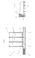
- Figure 3B shows the embodiment of Figure 3A in side view.
- Figure 4 shows, in perspective view, a fourth embodiment of an apparatus according to the invention.
- Figure 5 shows a detailed view of a separating element of the embodiment of Figure 4 .
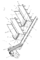
- Figure 6 shows, in perspective view, a fifth embodiment of an apparatus according to the invention.
- Figure 7 shows a detailed view of a separating element of the embodiment of Figure 6 .
- FIG. 1 shows an apparatus 1 according to the invention for separating and mixing feed for livestock.
- the apparatus 1 is provided with conveyor alleys 2 comprising conveying means 3 for conveying bales of feed 4 from a supply side 5 to a discharge side 6.
- the conveying means 3 can for instance consist of a conveyor belt or a chain conveyor provided with carriers.
- the apparatus 1 is provided with a separating element 7 for separating the feed.
- the separating element 7 comprises a guide frame 8, along which a knife 9 can be moved up and down with the aid of driving means (not shown) at a slight angle to the vertical, so that the cutting face of the bale 4 is rearwardly inclined.
- the separating element 7 further comprises a separating roll or crab roll 10 for pushing the separated feed away from the knife 9 and placing it on a conveyor belt 11.
- the separating roll 10 in that case is driven by driving means (not shown).
- the conveyor belt 11 travels the along the width of the discharge sides 6 of the two conveyor alleys 2, with the conveyor alleys 2 extending beyond the conveyor belt 11 for a short distance in order to prevent the possibility of separated chunks of feed falling beside the conveyor belt 11.
- the conveyor belt 11 conveys the feed which has been cut off and collected to a belt conveyor 12 moving in an inclined upward direction, which belt conveyor then puts the feed in a mixing bin 13.
- the mixing bin 13 is suspended from a weigh bar 14.
- the conveyor alleys 2 are additionally provided with vertical sideboards 15 on either side of the conveying means 3.
- the different conveyor alleys 2 can be used to supply different types of feed, but it is also possible for two or more of the conveyor alleys to convey the same type of feed. In this way it is possible to obtain an optimised composite feed menu for the livestock to be fed.
- FIG. 2 shows, in top view, an alternative embodiment of an apparatus according to the invention.
- the apparatus 21 comprises a number of conveyor alleys 22 each with a supply side 23 and a discharge side 24.
- the discharge side 24 of each of the conveyor alleys 22 opens into a central, shared conveyor belt 26.
- the conveyor alleys 22 are disposed parallel with one another, alternately on either side of the conveyor belt 26.
- Each of the conveyor alleys 22 is provided at the discharge side 24 with a separating element 25 shown schematically here.
- the separating element 25 can be configured as a cutting unit, such as a cutting knife as described in Figure 1 , or a cutter, band saw or circular saw, etc.
- the conveyor belt 26 conveys the separated feed to a belt conveyor 27 moving in an inclined upward direction, which puts the feed in a mixing bin or mixing robot 28.
- a third possible embodiment is depicted schematically in Figures 3A and 3B , in top and side view, respectively.
- This embodiment comprises an apparatus 31 with a number of conveyor alleys 32 disposed parallel with one another side by side, with a supply side 33 and a discharge side 34.
- a shared conveyor belt 36 runs along the full width of the discharge sides 34 of all conveyor alleys 32 and conveys separated feed to a belt conveyor 37 moving in an inclined upward direction, which puts the feed in a mixing bin or mixing robot (not shown).
- a separating element 35 extends across the entire width of the joint discharge ends 34 of the conveyor alleys 32.
- the separating element 35 comprises a cylindrical cutter 38, which can be moved up and down by way of a frame 39.
- the supply means of the conveyor alley 32 on which the bale in question is placed are driven to convey the bale to the discharge end 34 of the conveyor alley 32 in question.
- the conveyor alley 32 can be conveyed in the opposite direction, so that the bale in question is moved away from the separating element 35.
- another bale of a different type of feed can then be conveyed towards the separating element 35 so that a desired amount can be removed from that bale next.
- the amounts removed fall onto the conveyor belt 36, which then passes the separated feed to the mixing bin.
- the conveyor belt 36 like the mixing bin, can be provided with weighing means. In this way it can be determined accurately how much feed there is in the mixing bin and on the conveyor belt 36.
- FIG 4 shows yet another possible embodiment, where an apparatus 41 is provided with conveyor alleys 42 for conveying bales of feed from a supply side 43 to a discharge side 44. Near the discharge sides 44 of the conveyor alleys at hand 42 the apparatus 41 is provided with a separating element 45 for separating the feed.
- a conveyor belt 46 is disposed on the discharge side 44 of each of the conveyor alleys 42. The conveyor belt 46 conveys the feed which has been cut off and collected to a belt conveyor 47 moving in an inclined upward direction, which then puts the feed in a mixing bin 48. Between the conveyor alleys 42 vertical sideboards 49 are arranged.
- the separating element 45 comprises a guide 50 consisting of two horizontal, parallel rails 51, 52, and a slide 53, which is shown in two different positions in Figure 4 .
- the slide 53 can be moved forward and backward by way of the guide 50 by a drive unit in the slide 53 in a direction parallel with the conveyor belt 46.
- a drive unit 54 is hinged by means of a hinged joint 59.
- Figure 5 shows a drive unit 54 in more detail.
- the drive units 54 can be swung from an operating position out of the way to a travelling position and back again.
- Mounted in the drive unit 54 are one or two knives 56, which can be moved up and down with the aid of driving means (not shown).
- a separating roll or scraping roll 55 is mounted in the drive unit 54, which can be driven by the drive unit 54.
- Figure 4 shows the separating element 45 in two different positions: In the Figure with the full line the separating element 45 is in the operating position, while in the Figure with the interrupted line the separating element 45 is in the travelling position. In the operating position the knife or the knives 56 and the separating rolls 55 are suspended at a slight angle to the vertical, for instance an angle of 10 - 30 degrees. As a result, a slice is cut off the bale with a rearwardly inclined cutting face.
- the separating roll 55 consists of an essentially cylindrical roll 58 having a length which preferably exceeds the height of the bales from which feed is to be separated.
- the cylindrical roll 56 is provided with serrated finns 57, which extend at regular interspacing in essentially axial direction, in which case they may be moving spiral-wise.
- the drive unit 54 with the separating roll 55 and the knife or the knives 56 is swung into the operating position.
- the knife or the knives 56 are driven to cut off feed from the bale at hand and the separating roll 55 is driven to push the removed feed away from the knife or the knives 56, so that it falls onto the conveyor belt 46.
- the knife or the knives 56 and the separating roll 55 are stopped and the drive unit 54 with the knife or the knives 56 and the separating roll 55 is swung out of the way.
- the slide 53 can then convey the drive unit 54 with the knife or the knives 56 and the separating roll 55 by way of the guide 50 to a next discharge container 42, where the knife or the knives 56 and the separating roll 55 can be swung back into the operating position to enable them to cut into a new bale, for instance of a different type of feed.
- FIG 6 shows a further possible embodiment of an apparatus 60 according to the invention provided with a separating element 75, which is shown in more detail in Figure 7 .
- the apparatus 60 comprises a number of conveyor alleys 62 disposed parallel with one another, which comprise conveying means 63 for conveying bales of feed from a supply side 65 to a discharge side 66.
- a conveyor belt 67 runs the full width of the discharge sides 66 of the conveyor alleys 62, with the conveyor alleys 62 extending over the conveyor belt 67 for a short distance.
- the conveyor belt 67 conveys the feed which has been cut off and collected to a belt conveyor 68 moving in an inclined upward direction, which then puts the feed in a mixing bin 69.
- vertical sideboards 70 are arranged between the conveyor alleys 62.
- the separating element 75 consists of a guide frame 73 with a teethed guide 71 along which a drive unit 74 can be moved in a direction which is at a slight angle to the vertical.
- the guide frame 73 comprises a horizontal guide 72 along which the drive unit 74 can be moved in horizontal direction.
- a circular saw 78 is mounted, which is driven by a drive motor 76.
- the drive unit 74 is further provided with a guide fence 77 to prevent the sawed off feed from being blown away and to guide the feed towards the conveyor belt.
- the saw 78 is engaged in cutting off feed from the top left-hand corner of a bale of feed 79.
- the drive unit with the saw 78 is moved to the right in horizontal direction.
- the saw 78 is moved back and moved downwards for a distance, after which the saw 78 is again moved to the right.
- Other cutting sequences are also possible, for instance ones with sawing from right to left, or ones where each time a vertical slice is sawed off, in which case after the sawing of each slice a saw is moved horizontally for a short distance to cut off a new vertical slice.
- the saw 78 scans the cutting face, with the cutting face also in this embodiment preferably being rearwardly inclined and being at an angle to the vertical.
- the drive unit 74 with the saw 78 can be swung out of the way, in the same way as described for the embodiment of Figures 4 and 5 .
- the saw 78 which has been swung out of the way can then be moved to a different conveyor alley, without coming into contact with bales of feed on conveyor alleys disposed in between. If so desired, the bales may alternatively be moved away from the discharge side of the conveyor alley for a distance.
Landscapes
- Life Sciences & Earth Sciences (AREA)
- Environmental Sciences (AREA)
- Birds (AREA)
- Animal Husbandry (AREA)
- Biodiversity & Conservation Biology (AREA)
- Feeding And Watering For Cattle Raising And Animal Husbandry (AREA)
- Apparatuses For Bulk Treatment Of Fruits And Vegetables And Apparatuses For Preparing Feeds (AREA)
- Crushing And Pulverization Processes (AREA)
Priority Applications (1)
| Application Number | Priority Date | Filing Date | Title |
|---|---|---|---|
| EP11176824.8A EP2386201B1 (de) | 2008-07-04 | 2009-07-02 | Vorichtung zum Trennen und Mischen von Futter für Nutztiere |
Applications Claiming Priority (1)
| Application Number | Priority Date | Filing Date | Title |
|---|---|---|---|
| NL2001757A NL2001757C2 (nl) | 2008-07-04 | 2008-07-04 | Inrichting voor het losmaken en mengen van voer voor vee. |
Related Child Applications (2)
| Application Number | Title | Priority Date | Filing Date |
|---|---|---|---|
| EP11176824.8A Division EP2386201B1 (de) | 2008-07-04 | 2009-07-02 | Vorichtung zum Trennen und Mischen von Futter für Nutztiere |
| EP11176824.8 Division-Into | 2011-08-08 |
Publications (3)
| Publication Number | Publication Date |
|---|---|
| EP2140758A2 true EP2140758A2 (de) | 2010-01-06 |
| EP2140758A3 EP2140758A3 (de) | 2010-06-02 |
| EP2140758B1 EP2140758B1 (de) | 2013-03-20 |
Family
ID=40139343
Family Applications (2)
| Application Number | Title | Priority Date | Filing Date |
|---|---|---|---|
| EP11176824.8A Not-in-force EP2386201B1 (de) | 2008-07-04 | 2009-07-02 | Vorichtung zum Trennen und Mischen von Futter für Nutztiere |
| EP09164428A Active EP2140758B1 (de) | 2008-07-04 | 2009-07-02 | Anlage und Verfahren zum Trennen und Mischen von Viehfutter |
Family Applications Before (1)
| Application Number | Title | Priority Date | Filing Date |
|---|---|---|---|
| EP11176824.8A Not-in-force EP2386201B1 (de) | 2008-07-04 | 2009-07-02 | Vorichtung zum Trennen und Mischen von Futter für Nutztiere |
Country Status (2)
| Country | Link |
|---|---|
| EP (2) | EP2386201B1 (de) |
| NL (1) | NL2001757C2 (de) |
Cited By (6)
| Publication number | Priority date | Publication date | Assignee | Title |
|---|---|---|---|---|
| NL2009261C2 (nl) * | 2012-08-01 | 2014-02-04 | Trioliet Holding B V | Verwerking van blokken of balen voer. |
| ES2528416A1 (es) * | 2014-07-01 | 2015-02-09 | Grupo Tatoma, S.L. | Planta estática de preparación de mezclas alimentarias para ganado rumiante |
| BE1022815B1 (nl) * | 2015-03-02 | 2016-09-13 | Vps Bvba | Inrichting, samenstel en werkwijze voor het voederen van dieren |
| WO2017069614A1 (en) * | 2015-10-23 | 2017-04-27 | Peeters Landbouwmachines B.V. | System for processing cattle feed |
| CN110367138A (zh) * | 2019-07-04 | 2019-10-25 | 嵩明县富达奶牛养殖有限公司 | 青贮饲料上料喂养一体装置 |
| US20220159925A1 (en) * | 2020-11-23 | 2022-05-26 | Trioliet B.V. | Apparatus and method for preloading a plurality of feed types of a feed mix for livestock and method for preparing feed mixes |
Citations (1)
| Publication number | Priority date | Publication date | Assignee | Title |
|---|---|---|---|---|
| EP1723846A1 (de) | 2005-05-19 | 2006-11-22 | Trioliet Mullos B.V. | Anlage und Verfahren zum Trennen und Mischen von Viehfutter |
Family Cites Families (5)
| Publication number | Priority date | Publication date | Assignee | Title |
|---|---|---|---|---|
| US3830438A (en) * | 1972-01-20 | 1974-08-20 | Hesston Corp | Machine for feeding materials from a stack |
| US6966512B1 (en) * | 2003-01-17 | 2005-11-22 | Simpson T Whipple | System for un-baling farm products |
| NL1023476C2 (nl) * | 2003-05-20 | 2004-11-24 | Rudolf Cornelus Franci Kuypers | Het mechanisch doseren van hooi. |
| NL1026841C2 (nl) * | 2004-08-13 | 2006-02-14 | Trioliet Mullos | Inrichting voor het losmaken en mengen van voer voor vee. |
| NL1028732C2 (nl) * | 2005-04-11 | 2006-10-12 | Trioliet Mullos | Inrichting voor het uithalen en verwerken van ruwvoer voor vee. |
-
2008
- 2008-07-04 NL NL2001757A patent/NL2001757C2/nl not_active IP Right Cessation
-
2009
- 2009-07-02 EP EP11176824.8A patent/EP2386201B1/de not_active Not-in-force
- 2009-07-02 EP EP09164428A patent/EP2140758B1/de active Active
Patent Citations (1)
| Publication number | Priority date | Publication date | Assignee | Title |
|---|---|---|---|---|
| EP1723846A1 (de) | 2005-05-19 | 2006-11-22 | Trioliet Mullos B.V. | Anlage und Verfahren zum Trennen und Mischen von Viehfutter |
Cited By (12)
| Publication number | Priority date | Publication date | Assignee | Title |
|---|---|---|---|---|
| NL2009261C2 (nl) * | 2012-08-01 | 2014-02-04 | Trioliet Holding B V | Verwerking van blokken of balen voer. |
| WO2014021716A1 (en) * | 2012-08-01 | 2014-02-06 | Trioliet Holding B.V. | Processing of blocks or bales of feed |
| US20150136886A1 (en) * | 2012-08-01 | 2015-05-21 | Cornelis Hendricus Liet | Processing of Blocks or Bales of Feed |
| EP2879483B1 (de) | 2012-08-01 | 2016-09-14 | Trioliet Holding B.V. | Verarbeitung von futterblöcken oder -ballen |
| US10674675B2 (en) | 2012-08-01 | 2020-06-09 | Trioliet Holding B.V. | Processing of blocks or bales of feed |
| ES2528416A1 (es) * | 2014-07-01 | 2015-02-09 | Grupo Tatoma, S.L. | Planta estática de preparación de mezclas alimentarias para ganado rumiante |
| WO2016001467A1 (es) * | 2014-07-01 | 2016-01-07 | Grupo Tatoma,S.L. | Planta estática de preparación de mezclas alimentarias para ganado rumiante |
| US10532362B2 (en) | 2014-07-01 | 2020-01-14 | Grupo Tatoma, S.L. | Static plant for preparing feed mixes for ruminant livestock |
| BE1022815B1 (nl) * | 2015-03-02 | 2016-09-13 | Vps Bvba | Inrichting, samenstel en werkwijze voor het voederen van dieren |
| WO2017069614A1 (en) * | 2015-10-23 | 2017-04-27 | Peeters Landbouwmachines B.V. | System for processing cattle feed |
| CN110367138A (zh) * | 2019-07-04 | 2019-10-25 | 嵩明县富达奶牛养殖有限公司 | 青贮饲料上料喂养一体装置 |
| US20220159925A1 (en) * | 2020-11-23 | 2022-05-26 | Trioliet B.V. | Apparatus and method for preloading a plurality of feed types of a feed mix for livestock and method for preparing feed mixes |
Also Published As
| Publication number | Publication date |
|---|---|
| EP2386201B1 (de) | 2014-09-10 |
| NL2001757C2 (nl) | 2010-01-05 |
| EP2140758B1 (de) | 2013-03-20 |
| EP2386201A2 (de) | 2011-11-16 |
| EP2386201A3 (de) | 2013-05-15 |
| EP2140758A3 (de) | 2010-06-02 |
Similar Documents
| Publication | Publication Date | Title |
|---|---|---|
| EP2386201B1 (de) | Vorichtung zum Trennen und Mischen von Futter für Nutztiere | |
| EP1935239B2 (de) | Vorrichtung und Verfahren zum Trennen und Mischen von Viehfutter | |
| US10674675B2 (en) | Processing of blocks or bales of feed | |
| EP2200791B1 (de) | Ablage-abtransportvorrichtung für lebensmittel-schnittgut und lebensmittel-schneidemaschine | |
| US5623868A (en) | Carrot processing machines | |
| US4018391A (en) | Controlled hay bale metering and feeding device | |
| JP4101153B2 (ja) | コンバインの刈取穀稈搬送構造 | |
| EP2220931B1 (de) | Vorrichtung zur Pflege von Liegeboxen in einem Stall | |
| EP3132674B1 (de) | Vorrichtung und verfahren zur trennung von viehfutter | |
| EP2820942B1 (de) | Greifhaken zur trennung von viehfutter | |
| DE112016000130T5 (de) | System für die Zubereitung von Tierfutter | |
| US3654977A (en) | Livestock feeding machine | |
| DE102009039826A1 (de) | Verfahren zum Sortieren von aus Produktlaiben erzeugten Produkten, Sortiervorrichtung hierfür und Schneidmaschine | |
| RU2069942C1 (ru) | Капустоуборочная машина | |
| FI117620B (fi) | Laite pitkänomaisten kappaleiden poistamiseksi etenkin hihnakuljettimella liikkuvasta hakemateriaalista | |
| CA2568004A1 (en) | In-feed distributing unit | |
| SE445420B (sv) | Anordning for utskerning och uttagning av block fran ett silofoderforrad |
Legal Events
| Date | Code | Title | Description |
|---|---|---|---|
| PUAI | Public reference made under article 153(3) epc to a published international application that has entered the european phase |
Free format text: ORIGINAL CODE: 0009012 |
|
| AK | Designated contracting states |
Kind code of ref document: A2 Designated state(s): AT BE BG CH CY CZ DE DK EE ES FI FR GB GR HR HU IE IS IT LI LT LU LV MC MK MT NL NO PL PT RO SE SI SK SM TR |
|
| PUAL | Search report despatched |
Free format text: ORIGINAL CODE: 0009013 |
|
| AK | Designated contracting states |
Kind code of ref document: A3 Designated state(s): AT BE BG CH CY CZ DE DK EE ES FI FR GB GR HR HU IE IS IT LI LT LU LV MC MK MT NL NO PL PT RO SE SI SK SM TR |
|
| 17P | Request for examination filed |
Effective date: 20101202 |
|
| 17Q | First examination report despatched |
Effective date: 20110114 |
|
| GRAP | Despatch of communication of intention to grant a patent |
Free format text: ORIGINAL CODE: EPIDOSNIGR1 |
|
| GRAS | Grant fee paid |
Free format text: ORIGINAL CODE: EPIDOSNIGR3 |
|
| GRAA | (expected) grant |
Free format text: ORIGINAL CODE: 0009210 |
|
| AK | Designated contracting states |
Kind code of ref document: B1 Designated state(s): AT BE BG CH CY CZ DE DK EE ES FI FR GB GR HR HU IE IS IT LI LT LU LV MC MK MT NL NO PL PT RO SE SI SK SM TR |
|
| REG | Reference to a national code |
Ref country code: GB Ref legal event code: FG4D |
|
| REG | Reference to a national code |
Ref country code: CH Ref legal event code: EP |
|
| REG | Reference to a national code |
Ref country code: IE Ref legal event code: FG4D |
|
| REG | Reference to a national code |
Ref country code: AT Ref legal event code: REF Ref document number: 601472 Country of ref document: AT Kind code of ref document: T Effective date: 20130415 |
|
| REG | Reference to a national code |
Ref country code: DE Ref legal event code: R096 Ref document number: 602009014090 Country of ref document: DE Effective date: 20130516 |
|
| PG25 | Lapsed in a contracting state [announced via postgrant information from national office to epo] |
Ref country code: LT Free format text: LAPSE BECAUSE OF FAILURE TO SUBMIT A TRANSLATION OF THE DESCRIPTION OR TO PAY THE FEE WITHIN THE PRESCRIBED TIME-LIMIT Effective date: 20130320 Ref country code: SE Free format text: LAPSE BECAUSE OF FAILURE TO SUBMIT A TRANSLATION OF THE DESCRIPTION OR TO PAY THE FEE WITHIN THE PRESCRIBED TIME-LIMIT Effective date: 20130320 Ref country code: NO Free format text: LAPSE BECAUSE OF FAILURE TO SUBMIT A TRANSLATION OF THE DESCRIPTION OR TO PAY THE FEE WITHIN THE PRESCRIBED TIME-LIMIT Effective date: 20130620 Ref country code: ES Free format text: LAPSE BECAUSE OF FAILURE TO SUBMIT A TRANSLATION OF THE DESCRIPTION OR TO PAY THE FEE WITHIN THE PRESCRIBED TIME-LIMIT Effective date: 20130701 Ref country code: BG Free format text: LAPSE BECAUSE OF FAILURE TO SUBMIT A TRANSLATION OF THE DESCRIPTION OR TO PAY THE FEE WITHIN THE PRESCRIBED TIME-LIMIT Effective date: 20130620 |
|
| REG | Reference to a national code |
Ref country code: NL Ref legal event code: T3 |
|
| REG | Reference to a national code |
Ref country code: LT Ref legal event code: MG4D |
|
| PG25 | Lapsed in a contracting state [announced via postgrant information from national office to epo] |
Ref country code: GR Free format text: LAPSE BECAUSE OF FAILURE TO SUBMIT A TRANSLATION OF THE DESCRIPTION OR TO PAY THE FEE WITHIN THE PRESCRIBED TIME-LIMIT Effective date: 20130621 Ref country code: FI Free format text: LAPSE BECAUSE OF FAILURE TO SUBMIT A TRANSLATION OF THE DESCRIPTION OR TO PAY THE FEE WITHIN THE PRESCRIBED TIME-LIMIT Effective date: 20130320 Ref country code: SI Free format text: LAPSE BECAUSE OF FAILURE TO SUBMIT A TRANSLATION OF THE DESCRIPTION OR TO PAY THE FEE WITHIN THE PRESCRIBED TIME-LIMIT Effective date: 20130320 Ref country code: LV Free format text: LAPSE BECAUSE OF FAILURE TO SUBMIT A TRANSLATION OF THE DESCRIPTION OR TO PAY THE FEE WITHIN THE PRESCRIBED TIME-LIMIT Effective date: 20130320 |
|
| PG25 | Lapsed in a contracting state [announced via postgrant information from national office to epo] |
Ref country code: BE Free format text: LAPSE BECAUSE OF FAILURE TO SUBMIT A TRANSLATION OF THE DESCRIPTION OR TO PAY THE FEE WITHIN THE PRESCRIBED TIME-LIMIT Effective date: 20130320 Ref country code: HR Free format text: LAPSE BECAUSE OF FAILURE TO SUBMIT A TRANSLATION OF THE DESCRIPTION OR TO PAY THE FEE WITHIN THE PRESCRIBED TIME-LIMIT Effective date: 20130320 |
|
| PG25 | Lapsed in a contracting state [announced via postgrant information from national office to epo] |
Ref country code: IS Free format text: LAPSE BECAUSE OF FAILURE TO SUBMIT A TRANSLATION OF THE DESCRIPTION OR TO PAY THE FEE WITHIN THE PRESCRIBED TIME-LIMIT Effective date: 20130720 Ref country code: SK Free format text: LAPSE BECAUSE OF FAILURE TO SUBMIT A TRANSLATION OF THE DESCRIPTION OR TO PAY THE FEE WITHIN THE PRESCRIBED TIME-LIMIT Effective date: 20130320 Ref country code: CZ Free format text: LAPSE BECAUSE OF FAILURE TO SUBMIT A TRANSLATION OF THE DESCRIPTION OR TO PAY THE FEE WITHIN THE PRESCRIBED TIME-LIMIT Effective date: 20130320 Ref country code: PT Free format text: LAPSE BECAUSE OF FAILURE TO SUBMIT A TRANSLATION OF THE DESCRIPTION OR TO PAY THE FEE WITHIN THE PRESCRIBED TIME-LIMIT Effective date: 20130722 Ref country code: RO Free format text: LAPSE BECAUSE OF FAILURE TO SUBMIT A TRANSLATION OF THE DESCRIPTION OR TO PAY THE FEE WITHIN THE PRESCRIBED TIME-LIMIT Effective date: 20130320 Ref country code: EE Free format text: LAPSE BECAUSE OF FAILURE TO SUBMIT A TRANSLATION OF THE DESCRIPTION OR TO PAY THE FEE WITHIN THE PRESCRIBED TIME-LIMIT Effective date: 20130320 |
|
| PG25 | Lapsed in a contracting state [announced via postgrant information from national office to epo] |
Ref country code: CY Free format text: LAPSE BECAUSE OF FAILURE TO SUBMIT A TRANSLATION OF THE DESCRIPTION OR TO PAY THE FEE WITHIN THE PRESCRIBED TIME-LIMIT Effective date: 20130320 Ref country code: PL Free format text: LAPSE BECAUSE OF FAILURE TO SUBMIT A TRANSLATION OF THE DESCRIPTION OR TO PAY THE FEE WITHIN THE PRESCRIBED TIME-LIMIT Effective date: 20130320 |
|
| PLBE | No opposition filed within time limit |
Free format text: ORIGINAL CODE: 0009261 |
|
| STAA | Information on the status of an ep patent application or granted ep patent |
Free format text: STATUS: NO OPPOSITION FILED WITHIN TIME LIMIT |
|
| PG25 | Lapsed in a contracting state [announced via postgrant information from national office to epo] |
Ref country code: DK Free format text: LAPSE BECAUSE OF FAILURE TO SUBMIT A TRANSLATION OF THE DESCRIPTION OR TO PAY THE FEE WITHIN THE PRESCRIBED TIME-LIMIT Effective date: 20130320 |
|
| 26N | No opposition filed |
Effective date: 20140102 |
|
| PG25 | Lapsed in a contracting state [announced via postgrant information from national office to epo] |
Ref country code: IT Free format text: LAPSE BECAUSE OF FAILURE TO SUBMIT A TRANSLATION OF THE DESCRIPTION OR TO PAY THE FEE WITHIN THE PRESCRIBED TIME-LIMIT Effective date: 20130320 Ref country code: MC Free format text: LAPSE BECAUSE OF FAILURE TO SUBMIT A TRANSLATION OF THE DESCRIPTION OR TO PAY THE FEE WITHIN THE PRESCRIBED TIME-LIMIT Effective date: 20130320 |
|
| REG | Reference to a national code |
Ref country code: CH Ref legal event code: PL |
|
| GBPC | Gb: european patent ceased through non-payment of renewal fee |
Effective date: 20130702 |
|
| REG | Reference to a national code |
Ref country code: DE Ref legal event code: R097 Ref document number: 602009014090 Country of ref document: DE Effective date: 20140102 |
|
| REG | Reference to a national code |
Ref country code: IE Ref legal event code: MM4A |
|
| PG25 | Lapsed in a contracting state [announced via postgrant information from national office to epo] |
Ref country code: CH Free format text: LAPSE BECAUSE OF NON-PAYMENT OF DUE FEES Effective date: 20130731 Ref country code: GB Free format text: LAPSE BECAUSE OF NON-PAYMENT OF DUE FEES Effective date: 20130702 Ref country code: LI Free format text: LAPSE BECAUSE OF NON-PAYMENT OF DUE FEES Effective date: 20130731 |
|
| PG25 | Lapsed in a contracting state [announced via postgrant information from national office to epo] |
Ref country code: IE Free format text: LAPSE BECAUSE OF NON-PAYMENT OF DUE FEES Effective date: 20130702 |
|
| PG25 | Lapsed in a contracting state [announced via postgrant information from national office to epo] |
Ref country code: SM Free format text: LAPSE BECAUSE OF FAILURE TO SUBMIT A TRANSLATION OF THE DESCRIPTION OR TO PAY THE FEE WITHIN THE PRESCRIBED TIME-LIMIT Effective date: 20130320 |
|
| PG25 | Lapsed in a contracting state [announced via postgrant information from national office to epo] |
Ref country code: TR Free format text: LAPSE BECAUSE OF FAILURE TO SUBMIT A TRANSLATION OF THE DESCRIPTION OR TO PAY THE FEE WITHIN THE PRESCRIBED TIME-LIMIT Effective date: 20130320 Ref country code: MT Free format text: LAPSE BECAUSE OF FAILURE TO SUBMIT A TRANSLATION OF THE DESCRIPTION OR TO PAY THE FEE WITHIN THE PRESCRIBED TIME-LIMIT Effective date: 20130320 |
|
| PG25 | Lapsed in a contracting state [announced via postgrant information from national office to epo] |
Ref country code: LU Free format text: LAPSE BECAUSE OF NON-PAYMENT OF DUE FEES Effective date: 20130702 Ref country code: MK Free format text: LAPSE BECAUSE OF FAILURE TO SUBMIT A TRANSLATION OF THE DESCRIPTION OR TO PAY THE FEE WITHIN THE PRESCRIBED TIME-LIMIT Effective date: 20130320 Ref country code: HU Free format text: LAPSE BECAUSE OF FAILURE TO SUBMIT A TRANSLATION OF THE DESCRIPTION OR TO PAY THE FEE WITHIN THE PRESCRIBED TIME-LIMIT; INVALID AB INITIO Effective date: 20090702 |
|
| REG | Reference to a national code |
Ref country code: FR Ref legal event code: PLFP Year of fee payment: 8 |
|
| REG | Reference to a national code |
Ref country code: FR Ref legal event code: PLFP Year of fee payment: 9 |
|
| REG | Reference to a national code |
Ref country code: FR Ref legal event code: PLFP Year of fee payment: 10 |
|
| PGFP | Annual fee paid to national office [announced via postgrant information from national office to epo] |
Ref country code: AT Payment date: 20190619 Year of fee payment: 11 |
|
| REG | Reference to a national code |
Ref country code: AT Ref legal event code: MM01 Ref document number: 601472 Country of ref document: AT Kind code of ref document: T Effective date: 20200702 |
|
| PG25 | Lapsed in a contracting state [announced via postgrant information from national office to epo] |
Ref country code: AT Free format text: LAPSE BECAUSE OF NON-PAYMENT OF DUE FEES Effective date: 20200702 |
|
| PGFP | Annual fee paid to national office [announced via postgrant information from national office to epo] |
Ref country code: NL Payment date: 20220728 Year of fee payment: 14 |
|
| PGFP | Annual fee paid to national office [announced via postgrant information from national office to epo] |
Ref country code: DE Payment date: 20220727 Year of fee payment: 14 |
|
| PGFP | Annual fee paid to national office [announced via postgrant information from national office to epo] |
Ref country code: FR Payment date: 20220725 Year of fee payment: 14 |
|
| REG | Reference to a national code |
Ref country code: DE Ref legal event code: R119 Ref document number: 602009014090 Country of ref document: DE |
|
| REG | Reference to a national code |
Ref country code: NL Ref legal event code: MM Effective date: 20230801 |
|
| PG25 | Lapsed in a contracting state [announced via postgrant information from national office to epo] |
Ref country code: NL Free format text: LAPSE BECAUSE OF NON-PAYMENT OF DUE FEES Effective date: 20230801 |
|
| PG25 | Lapsed in a contracting state [announced via postgrant information from national office to epo] |
Ref country code: NL Free format text: LAPSE BECAUSE OF NON-PAYMENT OF DUE FEES Effective date: 20230801 Ref country code: DE Free format text: LAPSE BECAUSE OF NON-PAYMENT OF DUE FEES Effective date: 20240201 |