EP2140278B1 - Method for determining electric parameters of a route section of a magnetic suspension railway - Google Patents
Method for determining electric parameters of a route section of a magnetic suspension railway Download PDFInfo
- Publication number
- EP2140278B1 EP2140278B1 EP07722341A EP07722341A EP2140278B1 EP 2140278 B1 EP2140278 B1 EP 2140278B1 EP 07722341 A EP07722341 A EP 07722341A EP 07722341 A EP07722341 A EP 07722341A EP 2140278 B1 EP2140278 B1 EP 2140278B1
- Authority
- EP
- European Patent Office
- Prior art keywords
- current
- stator section
- stator
- section
- parameters
- Prior art date
- Legal status (The legal status is an assumption and is not a legal conclusion. Google has not performed a legal analysis and makes no representation as to the accuracy of the status listed.)
- Not-in-force
Links
Images


Classifications
-
- G—PHYSICS
- G01—MEASURING; TESTING
- G01R—MEASURING ELECTRIC VARIABLES; MEASURING MAGNETIC VARIABLES
- G01R27/00—Arrangements for measuring resistance, reactance, impedance, or electric characteristics derived therefrom
- G01R27/28—Measuring attenuation, gain, phase shift or derived characteristics of electric four pole networks, i.e. two-port networks; Measuring transient response
-
- B—PERFORMING OPERATIONS; TRANSPORTING
- B60—VEHICLES IN GENERAL
- B60M—POWER SUPPLY LINES, AND DEVICES ALONG RAILS, FOR ELECTRICALLY- PROPELLED VEHICLES
- B60M3/00—Feeding power to supply lines in contact with collector on vehicles; Arrangements for consuming regenerative power
-
- G—PHYSICS
- G01—MEASURING; TESTING
- G01R—MEASURING ELECTRIC VARIABLES; MEASURING MAGNETIC VARIABLES
- G01R31/00—Arrangements for testing electric properties; Arrangements for locating electric faults; Arrangements for electrical testing characterised by what is being tested not provided for elsewhere
- G01R31/34—Testing dynamo-electric machines
- G01R31/346—Testing of armature or field windings
Definitions
- the invention relates to a method having the features according to the preamble of claim 1.
- the route cable A communicates with its feed terminal 40 via switches Sua and Ska with a converter URA in combination.
- the further track cable B is connected to its feed connection 50 via switches Sub and Skb with a further converter URB in connection.
- measurements are made at the feed connection 40 and at the feed connection 50 with a converter-related measuring device 60 and a further converter-related measuring device 70, which can be connected to an evaluation device 90, for example via a current control 80 of the magnetic levitation train.
- the switches Se and Sub are opened and the voltages Ua and the currents Ia for an open circuit cable end (Skb open) and a closed path cable end (Skb closed) are measured.
- the switches Se and Sua are opened and the voltages Ub and the currents Ib are measured for an open circuit cable end (Ska open) and a closed path cable end (Ska closed).
- the electrical parameters of the two route cables A and B are determined.
- the properties of the stator section 10 are subsequently recalculated from current readings of the currents Ia and Ib and voltage readings of the voltages Ua and Ub, which are determined when the switch Se is closed. Such recalculation is possible since the properties of the two track cables A and B are already known separately from the stator section 10 at this time.
- a disadvantage of the previously known method is that the measurements must be carried out with the utmost care in order to avoid damage to the converter devices URA and URB.
- short-circuit measurement ie when the switches Ska or Skb are closed, short-circuit currents can flow with very large harmonic components, as a result of which semiconductor valves contained under circumstances in the converter devices can be destroyed.
- the invention is therefore an object of the invention to provide a method for parameter determination, in which the risk of damage to the inverter devices avoided, at least significantly reduced.
- the current and voltage values at the electrical connection between the track cable and the converter device are measured, when the stator section is electrically connected to the track cable, additionally the current and voltage values at the electrical connection between the track cable and the stator section and the current values at the star point side of the stator section are measured and these additional measured values are also taken into account when determining the parameters.
- a significant advantage of the method according to the invention is the fact that the risk of damage to the inverter devices is relatively low; because of during the measurements parallel-connected stator section, the current harmonic components are shifted in frequency and distributes the natural frequencies of the overall electrical system compared to a measurement with switched-off stator significantly cheaper.
- the short-circuit measurements with closed switches Ska and Skb thus correspond to electrical states which can occur during normal operation of the maglev train, so that the risk of destruction of the converter devices during the parameter determination is relatively low.
- the parameters can be determined particularly simply and thus advantageously when the measured values are evaluated with the aid of the quadrupole series.
- the stator section can be connected to a further converter device via a further line cable: in this case it is considered advantageous if the current and voltage values at the electrical connection point between the further line cable and the further converter device also occur when the stator section is switched on are measured and these measured values are additionally taken into account when determining the parameters.
- one or more of the following parameters are preferably determined: the electrical resistance, the inductance, the capacitance, the electrical resistance coating, the inductance coating, the dissipation coating, the capacitance coating and / or the conductance, be it for the track cable or the additional track cable and / or the stator section.
- the current and voltage values at the electrical connection between the track cable and the converter device and the current and voltage values at the electrical connection point between the track cable and the stator section are each measured in three phases and evaluated phase-phase-individually.
- the current and voltage values at the electrical connection point between the track cable and the stator section and the current values at the star point side of the stator section can be detected by a mobile measuring device and transmitted to a stationary evaluation device with which the parameters are then determined.
- the current and voltage values at the electrical connection point between the track cable and the stator section and the current values at the neutral point side of the stator section can be detected by a stationary measuring device and transmitted to a stationary evaluation device with which the parameters are then determined.
- the current and voltage values at the electrical connection between the track cable and the inverter, the current and voltage values at the electrical connection between the track cable and the stator section, and the current values at the neutral point side of the stator section during operation of the magnetic levitation train at least once, preferably repeatedly, measured in order to determine the parameters resulting from the measured values and to use the respectively current parameters for updating the parameter set.
- the current and voltage values at the electrical connection between the track cable and the stator section also to be used during the operation of the maglev train to determine the position of a vehicle on the stator section.
- the current values on the star point side of the stator section are preferably additionally used.
- the measured star point current is considered approximately as a stator current below a vehicle located on the stator section and under this assumption, the thrust force of the maglev is adjusted.
- the invention also relates to an arrangement for determining a parameter set which describes electrical parameters of a section of a maglev train, the track section comprising a stator section forming a drive section of the maglev train and a track cable connecting the stator section to an associated converter device, wherein the arrangement a converter-related measuring device, which is connected to the electrical connection point between the track cable and the inverter device and during its operation measures the current and voltage values at the connection point, and wherein the arrangement comprises an evaluation device which communicates with the converter-related measuring device and with the measured values of the Umrichter devisun measuring device determines the parameters of the parameter set and thus forms the parameter set.
- the arrangement additionally has a stator-related measuring device, which has the input side to the electrical connection point between the track cable and the stator and to the neutral point side of the stator is connected and the output side is in communication with the evaluation device, wherein the stator-related measuring device is configured such that it measures the current and voltage values at the junction between the track cable and the stator and the current values at the neutral point side during their operation and transmits them to the evaluation device , wherein the evaluation device is designed such that it additionally takes into account the measured values of the stator-related measuring device in the determination of the parameters and performs the measurements when the stator section is electrically connected to the track cable.
- the arrangement has a further converter-related measuring device which is connected on the input side to the electrical connection point between a further line cable and a further converter device and on the output side to the evaluation device and which is designed such that during its operation the current and voltage values at the connection point measures between the other link cable and the other converter device and transmits them to the evaluation device.
- the stator-related measuring device may be formed by a mobile unit or by a stationary unit.
- the evaluation device may be part of such a mobile or stationary unit or form a separate component.
- the arrangement is configured such that, after determining the parameters, the current and voltage values at the electrical connection point between the track cable and the converter device, the current and voltage values at the electrical connection point between the Track cable and the stator section and the current values at the neutral point side of the stator during the operation of the magnetic levitation train at least once again, preferably repeatedly measures the respectively resulting from the measured values parameters and uses the respective current parameters for updating the parameter set.
- the evaluation device can also be designed such that it determines the position of a vehicle on the stator section with the current and voltage values at the electrical connection point between the track cable and the stator section during operation of the magnetic levitation train. In addition, it can also use the current values at the neutral point side of the stator section to determine the position of the vehicle.
- a magnetic levitation train is considered with a plurality of sections, wherein at least one of the sections, preferably all sections, each with an individual, decentralized arrangement - as described - is equipped to determine a parameter set and provided for each with a decentralized arrangement Section each of the thrust power of the section is determined by using its decentralized determined parameter set.
- an arrangement and a method for locating a vehicle on a section of a magnetic levitation railway is also considered, regardless of how the parameters or parameter sets for the maglev were determined.
- an independent invention is also an arrangement and a method for adjusting the thrust power for a vehicle located on a section of a magnetic levitation railway is considered, in which the neutral-point current of the stator is regarded as a stator current below the vehicle and used to adjust the thrust power.
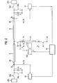
- FIG. 2 an embodiment of an inventive arrangement is shown.
- This arrangement is in accordance with the arrangement according to the FIG. 1 a stator section 10, a track cable A, a further track cable B, a plurality of switches Se, Ss, Sua, Ska, Sub and Skb, a converter URA, a further converter URB, a converter-related measuring device 60, another Inverter-related measuring device 70 and a current control 80 for the magnetic levitation on.
- stator-related, mobile or stationary measuring device which is designated by the reference numeral 100 and the input side is electrically connected to the junction 20 between the two line cables A and B and the stator section 10 and to the neutral point side 30 of the stator.
- the stator-related measuring device 100 On the output side, the stator-related measuring device 100 is connected to an evaluation device 110.
- the stator-related measuring device 110 is designed such that during its operation it measures the current and voltage values Ix, Ux at the connection point 20 between the line cables A, B and the stator section 10 as well as the star point current values Is at the star point side 30 and transmits them to the evaluation device 110 ,
- the evaluation device 110 with the two converter-related measuring devices 60 and 70 only indirectly via the stator-related measuring device 100 in connection, so that the inverter-related measurement results Ia, Ib, Ua, Ub the inverter-related measuring devices 60 and 70 only about the stator-related measuring device 100 to the evaluation device 110 arrive can.
- the evaluation device 110 can also be connected to one of the two converter-related measuring devices 60 or 70 and receive the measurement results of the other measuring devices via them. It is likewise possible to connect the evaluation device 110 directly to all measuring devices 60, 70 and 100, so that an immediate transmission of the measurement results is possible.
- the evaluation device 110 uses these measurement results to determine the electrical parameters of the two extension cables A and B as well as those of the stator section 10 using the quadrupole theory, as will be explained in detail below.
- the conductance matrix of a track cable or a stator section is completely symmetrical in accordance with Equations 2 and 3.
- the characteristics of the diagonal and the transverse admittance as a function of the frequency can be determined by means of various measurements (eg voltage excitations during startup) as a function of the frequency.
- R ', L', G 'and C' The purpose of determining R ', L', G 'and C' is to derive models for the two track cables A, B and the stator section 10.
- the models are used for example for the current control of the maglev train.
- the quadrupole representation as they are based on the FIG. 3 is explained in general, it is based on the arrangement according to the FIG. 2 applied; this shows the FIG. 4 ,
- the switches Se, Ss, Sua, Ska, Sub and Skb are in the FIG. 4 not shown; the switches Se and Ss are assumed to be on.
- stator current Ic on the stator section 10 corresponds to the neutral point current Is of the stator section 10; This approximation is very accurate for small frequencies up to 350 hertz.
- the leakage resistance R ⁇ and the leakage inductance L ⁇ may be used for the calculation of the pole wheel voltage UC during operation of the stator portion 10 with a vehicle; this will be explained in more detail below.
- the two route cables A and B are identical.
- Equation 12 The admittances Y Db and Y Cb are previously calculated from equations 22 and 23. Since the currents and voltages in Equation 12 are now known, the components of the conductance matrix [Y a ], namely Y Da and Y Ca are also determinable. Equations 6 to 13 thus also yield the values R a ', L a ', G a 'and C a ' of the track cable A.
- the parameters can thus be determined unambiguously by means of the measured values of the three measuring devices 60, 70 and 100.
- stator section 10 behaves a little differently than during startup without a vehicle.
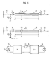
- FIG. 5 1 shows the stator section 10 with a vehicle F traveling at a speed v, which is currently occupying a relative position x on the stator section 10.
- the vehicle F may be represented electrically as a point voltage Uc.
- Obsch R ⁇ + s ⁇ L ⁇ ⁇ I x .
- the leakage resistance R ⁇ and the leakage inductance L ⁇ can then be determined by means of this harmonic model, as described in the document " Sensorless Control of a 2.4MW Linear Motor for launching roller-coasters "(EPE 2003 - Toulouse (ISBN: 90-75815-07-7), authors: Andre Veltman, Paul van der Hulst, Marco CP Jonker, Jan P. van Gurp ) is described.
- I a I b I x Y Daa 0 Y Ca 0 Y cb Y dbb - Y Dax - Y dbx - Y Ca + Y cb ⁇ U a U b U x
- Equation 33 all measurable quantities (I a , I b , I x , U a , U b and U x ) are combined in a single equation.
- the conductance matrix is now a 3x3 matrix (3 equations).
- the six unknown conductances ( Y Daa , Y Dax , Y Ca , Y Dbb , Y DBx, and Y Cb ) can be easily determined since at least six equations are available.
- the six equations can be established by measuring the currents and the voltages at two different sampling instants, as the currents and the voltages change over time. Incidentally, measurements at several sampling times also statistically improve the quality of parameter estimation.
- I denotes a current vector
- U a voltage vector
- e an error vector (vector with the dimension 3x1)
- Y a real conductance matrix
- ⁇ an estimated conductance matrix
- Equation 36 This formulation is a known problem (according to Gauss), where N denotes the number of measurements at several sampling times. There are many methods for solving Equation 36, for example, by minimizing J.
- Equation 37 is applicable during operation of the maglev when the two switches Se and Ss are closed.
- the phase angle of Ux is measured, with the phase angle of Ux the pole wheel angle ⁇ of the voltage Uc is determined and with the pole wheel angle ⁇ the location of the vehicle is calculated.
Landscapes
- Engineering & Computer Science (AREA)
- Mechanical Engineering (AREA)
- Physics & Mathematics (AREA)
- General Physics & Mathematics (AREA)
- Electric Propulsion And Braking For Vehicles (AREA)
- Control Of Vehicles With Linear Motors And Vehicles That Are Magnetically Levitated (AREA)
- Arc Welding Control (AREA)
Abstract
Description
Die Erfindung bezieht sich auf ein Verfahren mit den Merkmalen gemäß dem Oberbegriff des Anspruchs 1.The invention relates to a method having the features according to the preamble of
Zur Steuerung einer Magnetschwebebahn, insbesondere zur Regelung des Schubkraftstroms einer Magnetschwebebahn, ist es erforderlich, die elektrischen Parameter der einzelnen Streckenabschnitte der Magnetschwebebahn möglichst genau zu kennen.To control a magnetic levitation train, in particular for controlling the thrust force of a magnetic levitation railway, it is necessary to know the electrical parameters of the individual sections of the magnetic levitation railway as accurately as possible.
Von der in Shanghai gebauten Transrapidstrecke ist es bekannt, für jeden Streckenabschnitt einen entsprechenden Parametersatz zu bestimmen. Ein Streckenabschnitt besteht dabei zumindest aus einem einen Antriebsabschnitt der Magnetschwebebahn bildenden Statorabschnitt und einem Streckenkabel, das den Statorabschnitt mit einer zugeordneten Umrichtereinrichtung verbindet. Zur Bestimmung des Parametersatzes werden die Strom- und Spannungswerte an der elektrischen Verbindungsstelle zwischen dem Streckenkabel und der Umrichtereinrichtung gemessen. Mit diesen Messwerten werden anschließend die Parameter des Parametersatzes ermittelt und damit der Parametersatz gebildet. Die vorbekannte Vorgehensweise zur Bestimmung der Parameter ist anhand der
- Man erkennt in der
Figur 1Statorabschnitt 10, dessen einerAnschluss 20 über einen Schalter Se mit einem Streckenkabel A und einem weiteren Streckenkabel B verbunden ist. DasStatorabschnittsanschluss 30 desStatorabschnitts 10 ist über einen Schalter Ss mit dem Sternpunkt verbunden.
- One recognizes in the
FIG. 1 astator section 10, whose oneterminal 20 is connected via a switch Se to a track cable A and another track cable B. TheStatorabschnittsanschluss 30 of thestator 10 is connected via a switch Ss to the neutral point.
Das Streckenkabel A steht mit seinem Einspeiseanschluss 40 über Schalter Sua und Ska mit einer Umrichtereinrichtung URA in Verbindung. Das weitere Streckenkabel B steht mit seinem Einspeiseanschluss 50 über Schalter Sub und Skb mit einer weiteren Umrichtereinrichtung URB in Verbindung.The route cable A communicates with its
Zur Bestimmung der Parameter des Streckenabschnitts werden mit einer umrichterbezogenen Messeinrichtung 60 und einer weiteren umrichterbezogenen Messeinrichtung 70, die beispielsweise über eine Stromregelung 80 der Magnetschwebebahn mit einer Auswerteinrichtung 90 verbunden sein können, Messungen am Einspeiseanschluss 40 sowie am Einspeiseanschluss 50 vorgenommen. Bei der Messung am Einspeiseanschluss 40 werden die Schalter Se und Sub geöffnet und die Spannungen Ua und die Ströme Ia für ein offenes Streckenkabelende (Skb offen) und ein geschlossenes Streckenkabelende (Skb geschlossen) gemessen. Bei der Messung am Einspeiseanschluss 50 werden die Schalter Se und Sua geöffnet und die Spannungen Ub und die Ströme Ib für ein offenes Streckenkabelende (Ska offen) und ein geschlossenes Streckenkabelende (Ska geschlossen) gemessen. Mit den entsprechenden Messwerten werden die elektrischen Parameter der beiden Streckenkabel A und B ermittelt. Die Eigenschaften des Statorabschnitts 10 werden nachfolgend aus Strommesswerten der Ströme Ia und Ib und Spannungsmesswerten der Spannungen Ua und Ub rückgerechnet, die bei geschlossenem Schalter Se bestimmt werden. Ein solches Rückrechnen ist möglich, da die Eigenschaften der beiden Streckenkabel A und B separat vom Statorabschnitt 10 zu diesem Zeitpunkt bereits bekannt sind.To determine the parameters of the route section, measurements are made at the
Nachteilig bei dem vorbekannten Verfahren ist, dass die Messungen mit äußerster Vorsicht durchgeführt werden müssen, um Beschädigungen an den Umrichtereinrichtungen URA und URB zu vermeiden. Bei der Kurzschlussmessung, wenn also die Schalter Ska oder Skb geschlossen sind, können Kurzschlussströme mit sehr großen Oberschwingungsanteilen fließen, wodurch unter Umstände in den Umrichtereinrichtungen enthaltene Halbleiterventile zerstört werden können.A disadvantage of the previously known method is that the measurements must be carried out with the utmost care in order to avoid damage to the converter devices URA and URB. In the short-circuit measurement, ie when the switches Ska or Skb are closed, short-circuit currents can flow with very large harmonic components, as a result of which semiconductor valves contained under circumstances in the converter devices can be destroyed.
Ausgehend von einem Verfahren der eingangs angegebenen Art liegt der Erfindung somit die Aufgabe zugrunde, ein Verfahren zur Parameterbestimmung anzugeben, bei dem die Gefahr einer Beschädigung der Umrichtereinrichtungen vermieden, zumindest deutlich reduziert ist.Based on a method of the type described above, the invention is therefore an object of the invention to provide a method for parameter determination, in which the risk of damage to the inverter devices avoided, at least significantly reduced.
Diese Aufgabe wird erfindungsgemäß durch ein Verfahren mit den Merkmalen gemäß Anspruch 1 gelöst. Vorteilhafte Ausgestaltungen des erfindungsgemäßen Verfahrens sind in Unteransprüchen angegeben.This object is achieved by a method with the features of
Danach ist erfindungsgemäß vorgesehen, dass die Strom- und Spannungswerte an der elektrischen Verbindungsstelle zwischen dem Streckenkabel und der Umrichtereinrichtung gemessen werden, wenn der Statorabschnitt mit dem Streckenkabel elektrisch verbunden ist, zusätzlich die Strom- und Spannungswerte an der elektrischen Verbindungsstelle zwischen dem Streckenkabel und dem Statorabschnitt sowie die Stromwerte an der Sternpunktseite des Statorabschnitts gemessen werden und diese zusätzlichen Messwerte beim Ermitteln der Parameter ebenfalls berücksichtigt werden.According to the invention, it is provided according to the invention that the current and voltage values at the electrical connection between the track cable and the converter device are measured, when the stator section is electrically connected to the track cable, additionally the current and voltage values at the electrical connection between the track cable and the stator section and the current values at the star point side of the stator section are measured and these additional measured values are also taken into account when determining the parameters.
Ein wesentlicher Vorteil des erfindungsgemäßen Verfahrens ist darin zu sehen, dass die Gefahr von Beschädigungen der Umrichtereinrichtungen relativ gering ist; aufgrund des während der Messungen parallel geschalteten Statorabschnitts sind die Stromoberschwingungsanteile frequenzmäßig verschoben und die Eigenfrequenzen des elektrischen Gesamtsystems gegenüber einer Messung mit abgeschaltetem Statorabschnitt deutlich günstiger verteilt. Die Kurzschlussmessungen mit geschlossenen Schaltern Ska bzw. Skb entsprechen somit elektrischen Zuständen, wie sie während des üblichen Betriebs der Magnetschwebebahn auftreten können, so dass die Gefahr einer Zerstörung der Umrichtereinrichtungen während der Parameterbestimmung relativ gering ist.A significant advantage of the method according to the invention is the fact that the risk of damage to the inverter devices is relatively low; because of during the measurements parallel-connected stator section, the current harmonic components are shifted in frequency and distributes the natural frequencies of the overall electrical system compared to a measurement with switched-off stator significantly cheaper. The short-circuit measurements with closed switches Ska and Skb thus correspond to electrical states which can occur during normal operation of the maglev train, so that the risk of destruction of the converter devices during the parameter determination is relatively low.
Besonders einfach und damit vorteilhaft lassen sich die Parameter bestimmen, wenn die Messwerte mit Hilfe der Vierpoltherie ausgewertet werden.The parameters can be determined particularly simply and thus advantageously when the measured values are evaluated with the aid of the quadrupole series.
Wie bereits eingangs erwähnt, kann der Statorabschnitt über ein weiteres Streckenkabel mit einer weiteren Umrichtereinrichtung verbunden sein: In diesem Falle wird es als vorteilhaft angesehen, wenn die Strom- und Spannungswerte an der elektrischen Verbindungsstelle zwischen dem weiteren Streckenkabel und der weiteren Umrichtereinrichtung bei eingeschaltetem Statorabschnitt ebenfalls gemessen werden und diese Messwerte beim Ermitteln der Parameter zusätzlich berücksichtigt werden.As already mentioned at the beginning, the stator section can be connected to a further converter device via a further line cable: in this case it is considered advantageous if the current and voltage values at the electrical connection point between the further line cable and the further converter device also occur when the stator section is switched on are measured and these measured values are additionally taken into account when determining the parameters.
Für den Parametersatz werden vorzugsweise einer oder mehrere der folgenden Parameter bestimmt: der elektrische Widerstand, die Induktivität, die Kapazität, der elektrische Widerstandsbelag, der Induktivitätsbelag, der Ableitungsbelag, der Kapazitätsbelag und/oder der Leitwert, sei es für das Streckenkabel, das weitere Streckenkabel und/oder den Statorabschnitt.For the parameter set, one or more of the following parameters are preferably determined: the electrical resistance, the inductance, the capacitance, the electrical resistance coating, the inductance coating, the dissipation coating, the capacitance coating and / or the conductance, be it for the track cable or the additional track cable and / or the stator section.
Vorzugsweise werden die Strom- und Spannungswerte an der elektrischen Verbindungsstelle zwischen dem Streckenkabel und der Umrichtereinrichtung und die Strom- und Spannungswerte an der elektrischen Verbindungsstelle zwischen dem Streckenkabel und dem Statorabschnitt jeweils dreiphasig gemessen und phasenleiterindividuell ausgewertet.Preferably, the current and voltage values at the electrical connection between the track cable and the converter device and the current and voltage values at the electrical connection point between the track cable and the stator section are each measured in three phases and evaluated phase-phase-individually.
Die Strom- und Spannungswerte an der elektrischen Verbindungsstelle zwischen dem Streckenkabel und dem Statorabschnitt sowie die Stromwerte an der Sternpunktseite des Statorabschnitts können mit einer mobilen Messeinrichtung erfasst und zu einer stationären Auswerteinrichtung übertragen werden, mit der dann die Parameter ermittelt werden.The current and voltage values at the electrical connection point between the track cable and the stator section and the current values at the star point side of the stator section can be detected by a mobile measuring device and transmitted to a stationary evaluation device with which the parameters are then determined.
Alternativ können die Strom- und Spannungswerte an der elektrischen Verbindungsstelle zwischen dem Streckenkabel und dem Statorabschnitt sowie die Stromwerte an der Sternpunktseite des Statorabschnitts mit einer stationären Messeinrichtung erfasst und zu einer stationären Auswerteinrichtung übertragen werden, mit der dann die Parameter ermittelt werden.Alternatively, the current and voltage values at the electrical connection point between the track cable and the stator section and the current values at the neutral point side of the stator section can be detected by a stationary measuring device and transmitted to a stationary evaluation device with which the parameters are then determined.
Nach dem Bestimmen der Parameter werden die Strom- und Spannungswerte an der elektrischen Verbindungsstelle zwischen dem Streckenkabel und der Umrichtereinrichtung, die Strom- und Spannungswerte an der elektrischen Verbindungsstelle zwischen dem Streckenkabel und dem Statorabschnitt sowie die Stromwerte an der Sternpunktseite des Statorabschnitts während des Betriebs der Magnetschwebebahn zumindest ein weiteres Mal, vorzugsweise wiederholt, gemessen, um die sich aus den Messwerten jeweils ergebenden Parameter zu ermitteln und die jeweils aktuellen Parameter zur Aktualisierung des Parametersatzes zu verwenden.After determining the parameters, the current and voltage values at the electrical connection between the track cable and the inverter, the current and voltage values at the electrical connection between the track cable and the stator section, and the current values at the neutral point side of the stator section during operation of the magnetic levitation train at least once, preferably repeatedly, measured in order to determine the parameters resulting from the measured values and to use the respectively current parameters for updating the parameter set.
Als besonders vorteilhaft wird es angesehen, wenn die Strom-und Spannungswerte an der elektrischen Verbindungsstelle zwischen dem Streckenkabel und dem Statorabschnitt auch dazu verwendet werden, während des Betriebs der Magnetschwebebahn die Position eines Fahrzeugs auf dem Statorabschnitt zu bestimmen. Zur Bestimmung der Position des Fahrzeugs werden vorzugsweise zusätzlich auch die Stromwerte an der Sternpunktseite des Statorabschnitts herangezogen.It is considered to be particularly advantageous if the current and voltage values at the electrical connection between the track cable and the stator section also to be used during the operation of the maglev train to determine the position of a vehicle on the stator section. To determine the position of the vehicle, the current values on the star point side of the stator section are preferably additionally used.
Auch wird es als vorteilhaft angesehen, wenn der gemessene Sternpunktstrom näherungsweise als Statorstrom unterhalb eines auf dem Statorabschnitt befindlichen Fahrzeugs angesehen wird und unter dieser Annahme der Schubkraftstrom der Magnetschwebebahn eingestellt wird.It is also considered advantageous if the measured star point current is considered approximately as a stator current below a vehicle located on the stator section and under this assumption, the thrust force of the maglev is adjusted.
Die Erfindung bezieht sich außerdem auf eine Anordnung zum Ermitteln eines Parametersatzes, der elektrische Parameter eines Streckenabschnitts einer Magnetschwebebahn beschreibt, wobei der Streckenabschnitt einen einen Antriebsabschnitt der Magnetschwebebahn bildenden Statorabschnitt und ein Streckenkabel, das den Statorabschnitt mit einer zugeordneten Umrichtereinrichtung verbindet, umfasst, wobei die Anordnung eine umrichterbezogene Messeinrichtung aufweist, die an die elektrischen Verbindungsstelle zwischen dem Streckenkabel und der Unrichtereinrichtung angeschlossen ist und während ihres Betriebs die Strom- und Spannungswerte an der Verbindungsstelle misst, und wobei die Anordnung eine Auswerteinrichtung aufweist, die mit der umrichterbezogenen Messeinrichtung in Verbindung steht und mit den Messwerten der umrichterbezogenun Meßeinrichtung die Parameter des Parametersatzes ermittelt und damit den Parametersatz bildet.The invention also relates to an arrangement for determining a parameter set which describes electrical parameters of a section of a maglev train, the track section comprising a stator section forming a drive section of the maglev train and a track cable connecting the stator section to an associated converter device, wherein the arrangement a converter-related measuring device, which is connected to the electrical connection point between the track cable and the inverter device and during its operation measures the current and voltage values at the connection point, and wherein the arrangement comprises an evaluation device which communicates with the converter-related measuring device and with the measured values of the Umrichterbezogenun measuring device determines the parameters of the parameter set and thus forms the parameter set.
Erfindungsgemäß ist bezüglich einer solchen Anordnung vorgesehen, dass die Anordnung zusätzlich eine statorbezogene Messeinrichtung aufweist, die eingangsseitig an die elektrische Verbindungsstelle zwischen dem Streckenkabel und dem Statorabschnitt sowie an die Sternpunktseite des Statorabschnitts angeschlossen ist und ausgangsseitig mit der Auswerteinrichtung in Verbindung steht, wobei die statorbezogene Messeinrichtung derart ausgestaltet ist, dass sie während ihres Betriebs die Strom- und Spannungswerte an der Verbindungsstelle zwischen dem Streckenkabel und dem Statorabschnitt sowie die Stromwerte an der Sternpunktseite misst und diese zur Auswerteinrichtung übermittelt, wobei die Auswerteinrichtung derart ausgestaltet ist, dass sie die Messwerte der statorbezogenen Messeinrichtung bei der Ermittlung der Parameter zusätzlich berücksichtigt und die Messungen durchführt, wenn der Statorabschnitt mit dem Streckenkabel elektrisch verbunden ist.According to the invention, it is provided with respect to such an arrangement that the arrangement additionally has a stator-related measuring device, which has the input side to the electrical connection point between the track cable and the stator and to the neutral point side of the stator is connected and the output side is in communication with the evaluation device, wherein the stator-related measuring device is configured such that it measures the current and voltage values at the junction between the track cable and the stator and the current values at the neutral point side during their operation and transmits them to the evaluation device , wherein the evaluation device is designed such that it additionally takes into account the measured values of the stator-related measuring device in the determination of the parameters and performs the measurements when the stator section is electrically connected to the track cable.
Vorzugsweise weist die Anordnung eine weitere umrichterbezogene Messeinrichtung auf, die eingangsseitig an die elektrische Verbindungsstelle zwischen einem weiteren Streckenkabel und einer weiteren Umrichtereinrichtung und ausgangsseitig an die Auswerteinrichtung angeschlossen ist und die derart ausgestaltet ist, dass sie während ihres Betriebs die Strom- und Spannungswerte an der Verbindungsstelle zwischen dem weiteren Streckenkabel und der weiteren Umrichtereinrichtung misst und diese zur Auswerteinrichtung übermittelt.Preferably, the arrangement has a further converter-related measuring device which is connected on the input side to the electrical connection point between a further line cable and a further converter device and on the output side to the evaluation device and which is designed such that during its operation the current and voltage values at the connection point measures between the other link cable and the other converter device and transmits them to the evaluation device.
Die statorbezogene Messeinrichtung kann durch eine mobile Einheit oder durch eine stationäre Einheit gebildet sein. Die Auswerteinrichtung kann Bestandteil einer solchen mobilen oder stationären Einheit sein oder eine separate Komponente bilden.The stator-related measuring device may be formed by a mobile unit or by a stationary unit. The evaluation device may be part of such a mobile or stationary unit or form a separate component.
Bevorzugt ist die Anordnung derart ausgestaltet, dass sie nach dem Bestimmen der Parameter die Strom- und Spannungswerte an der elektrischen Verbindungsstelle zwischen dem Streckenkabel und der Umrichtereinrichtung, die Strom- und Spannungswerte an der elektrischen Verbindungsstelle zwischen dem Streckenkabel und dem Statorabschnitt sowie die Stromwerte an der Sternpunktseite des Statorabschnitts während des Betriebs der Magnetschwebebahn zumindest ein weiteres Mal, vorzugsweise wiederholt, misst, die sich aus den Messwerten jeweils ergebenden Parameter ermittelt und die jeweils aktuellen Parameter zur Aktualisierung des Parametersatzes verwendet.Preferably, the arrangement is configured such that, after determining the parameters, the current and voltage values at the electrical connection point between the track cable and the converter device, the current and voltage values at the electrical connection point between the Track cable and the stator section and the current values at the neutral point side of the stator during the operation of the magnetic levitation train at least once again, preferably repeatedly measures the respectively resulting from the measured values parameters and uses the respective current parameters for updating the parameter set.
Außerdem kann die Auswerteinrichtung auch derart ausgestaltet sein, dass sie mit den Strom- und Spannungswerten an der elektrischen Verbindungsstelle zwischen dem Streckenkabel und dem Statorabschnitt während des Betriebs der Magnetschwebebahn die Position eines Fahrzeugs auf dem Statorabschnitt bestimmt. Zusätzlich kann sie zur Bestimmung der Position des Fahrzeugs auch die Stromwerte an der Sternpunktseite des Statorabschnitts heranziehen.In addition, the evaluation device can also be designed such that it determines the position of a vehicle on the stator section with the current and voltage values at the electrical connection point between the track cable and the stator section during operation of the magnetic levitation train. In addition, it can also use the current values at the neutral point side of the stator section to determine the position of the vehicle.
Als Erfindung wird darüber hinaus eine Magnetschwebebahn mit einer Vielzahl an Streckenabschnitten angesehen, wobei zumindest einer der Streckenabschnitte, vorzugsweise alle Streckenabschnitte, jeweils mit einer individuellen, dezentralen Anordnung - wie beschrieben - zum Ermitteln eines Parametersatzes ausgestattet ist und wobei für jeden mit einer dezentralen Anordnung versehenen Streckenabschnitt jeweils der Schubkraftstrom des Streckenabschnitts unter Heranziehung seines dezentral ermittelten Parametersatzes ermittelt wird.As an invention, moreover, a magnetic levitation train is considered with a plurality of sections, wherein at least one of the sections, preferably all sections, each with an individual, decentralized arrangement - as described - is equipped to determine a parameter set and provided for each with a decentralized arrangement Section each of the thrust power of the section is determined by using its decentralized determined parameter set.
Als selbständige Erfindung wird darüber hinaus eine Anordnung und ein Verfahren zum Orten eines Fahrzeugs auf einem Streckenabschnitt einer Magnetschwebebahn angesehen, und zwar unabhängig davon, wie die Parameter bzw. Parametersätze für die Magnetschwebebahn ermittelt worden sind.As an independent invention, an arrangement and a method for locating a vehicle on a section of a magnetic levitation railway is also considered, regardless of how the parameters or parameter sets for the maglev were determined.
Als selbständige Erfindung wird darüber hinaus eine Anordnung und ein Verfahren zum Einstellen des Schubkraftstromes für ein auf einem Streckenabschnitt einer Magnetschwebebahn befindliches Fahrzeug angesehen, bei dem der Sternpunktstrom des Statorabschnitts als Statorstrom unterhalb des Fahrzeugs angesehen und zum Einstellen des Schubkraftstromes verwendet wird.As an independent invention is also an arrangement and a method for adjusting the thrust power for a vehicle located on a section of a magnetic levitation railway is considered, in which the neutral-point current of the stator is regarded as a stator current below the vehicle and used to adjust the thrust power.
Die Erfindung wird nachfolgend anhand von Ausführungsbeispielen näher erläutert; dabei zeigen beispielhaft
- Figur 2
- ein Ausführungsbeispiel für eine erfindungsgemä- ße Anordnung, anhand derer auch das erfindungs- gemäße Verfahren beispielhaft erläutert wird,
- Figur 3
- allgemeine Erläuterungen zur Vierpoltheorie,
- Figur 4
- die Vierpoltheorie angewandt auf die Anordnung gemäß der
Figur 2 und - Figur 5
- schematisch die Ortsbestimmung eines Fahrzeugs, das sich auf einem Statorabschnitt der Anordnung gemäß der
Figur 2 befindet.
- FIG. 2
- An exemplary embodiment of an arrangement according to the invention, by means of which the method according to the invention is also explained by way of example,
- FIG. 3
- general explanations of the four-pole theory,
- FIG. 4
- the quadrupole theory applied to the arrangement according to the
FIG. 2 and - FIG. 5
- schematically the location of a vehicle, which is located on a stator of the arrangement according to the
FIG. 2 located.
In den
In der
Zusätzlich ist bei der Anordnung gemäß der
Bei dem Ausführungsbeispiel gemäß der
Die Anordnung gemäß der
- Mit der umrichterbezogenen Messeinrichtung 60 werden der in das Streckenkabel A hineinfließende Strom Ia und die am Streckenkabel A anliegende Spannung Ua gemessen. Mit der weiteren umrichterbezogenen Messeinrichtung 70 wird der in das weitere Streckenkabel B hineinfließende Strom Ib und die am weiteren Streckenkabel B anliegende Spannung Ub gemessen. Mit der statorbezogenen Messeinrichtung 100 werden der Strom Ix und die Spannung Ux an der elektrischen Verbindungsstelle 20 zwischen den Streckenkabeln A, B
und dem Statorabschnitt 10 sowie der Strom Is an der Sternpunktseite des Statorabschnitts 10 gemessen.
- With the converter-related
measuring device 60, the current Ia flowing into the route cable A and the voltage Ua applied to the route cable A are measured. The further converter-relatedmeasuring device 70 measures the current Ib flowing into the further track cable B and the voltage Ub applied to the further track cable B. With the stator-relatedmeasuring device 100, the current Ix and the voltage Ux at theelectrical connection point 20 between the line cables A, B and thestator section 10 and the current Is at the neutral point side of thestator section 10 are measured.
Die Auswerteinrichtung 110 ermittelt mit diesen Messergebnissen die elektrischen Parameter der beiden Streckenkabel A und B sowie die des Statorabschnitts 10 unter Heranziehung der Vierpoltheorie, wie nachfolgend im Detail erläutert wird.The
Die elektrischen Eigenschaften eines langen Streckenkabels bzw. eines langen Statorabschnitts können gemäß Vierpoltheorie mathematisch wie folgt dargestellt werden: 
Die Spannungen U1 und U2 sind von Natur aus die Anregungen und die Ströme I1 und I2 sind die Antworten darauf. Die Spannungen und die Ströme sind komplex und können z.B. in αβ-Darstellung, die aus der dreiphasigen Systemdarstellung (R, S und T) abgeleitet werden kann, dargestellt werden. Yij sind Admittanzen, die von der Frequenz abhängig sind (s-Domain nach Laplace). Schematisch kann die Vierpoltheorie wie in Figur 3 dargestellt visualisiert werden. Die Leitwertmatrix wird als [Y] bezeichnet. Die Struktur der Leitwertmatrix eines Streckenkabels und eines Statorabschnitts mit einer Länge L sind dabei identisch:
- Für die Diagonal-Admittanz gilt:

- Für die Quer-Admittanz gilt:

- For the diagonal admittance:
- For the transverse admittance, the following applies:
Die Leitwertmatrix eines Streckenkabels bzw. eines Statorabschnitts ist gemäß Gleichung 2 und 3 vollkommen symmetrisch.The conductance matrix of a track cable or a stator section is completely symmetrical in accordance with Equations 2 and 3.
Zw bildet die Wellenimpedanz, mit 
und γ ist die Ausbreitungskonstante: 
and γ is the propagation constant:
Hier sind:
- R' der Widerstandsbelag (Ω/m),
- L' der Induktivitätsbelag (H/m),
- G' der Ableitungsbelag(Ω-1/m) und
- C' der Kapazitätsbelag (F/m).
- R 'is the resistance coating (Ω / m),
- L 'the inductance coating (H / m),
- G 'is the derivative coating (Ω -1 / m) and
- C 'is the capacity floor (F / m).
Wichtige Eigenschaften der Gleichungen 2 und 3 ergeben sich gemäß: 

Aus YD und YC sind Zw und γ abzuleiten.From Y D and Y C , Z w and γ are derived.
Der Impedanzbelag wird auf folgende Weise berechnet: ![]()
![]()
Der Admittanzbelag wird folgendermaßen berechnet: 
Mit s = jω kann man aus Gleichung 6 und Gleichung 7 weiterhin folgende Beziehungen ableiten:The admittance score is calculated as follows:
With s = jω, one can derive the following relationships from Equation 6 and Equation 7:
Der Widerstandsbelag ist der reelle Teil des Impedanzbelags: ![]()
![]()
Der Induktivitätsbelag ist der imaginäre Teil des Impedanzbelags: 
Der Ableitungsbelag ist der reelle Teil des Admittanzbelags: ![]()
![]()
Der Kapazitätsbelag ist der imaginäre Teil des Admittanzbelags: 
Wenn die Kennlinien der Diagonal- und der Quer-Admittanz eines Streckenkabels bzw. eines Statorabschnitts bekannt sind (als Funktion von der Frequenz), dann sind auch die Kennlinien der elektrischen Beläge R', L', G' und C' bekannt, sofern die Länge L des Streckenkabels bzw. des Statorabschnitts bekannt ist, weil sie beispielsweise vorab gemessen worden ist.If the characteristics of the diagonal and the transverse admittance of a track or a Statorabschnitts are known (as a function of frequency), then the characteristics of the electrical deposits R ', L', G 'and C' are known, provided that Length L of the track cable or the stator section is known because it has been measured in advance, for example.
Die Kennlinien der Diagonal- und der Quer-Admittanz als Funktion von der Frequenz können mittels verschiedener Messungen (z. B. Spannungserregungen während der Inbetriebsetzung) als Funktion von der Frequenz ermittelt werden.The characteristics of the diagonal and the transverse admittance as a function of the frequency can be determined by means of various measurements (eg voltage excitations during startup) as a function of the frequency.
Der Zweck der Ermittlung von R', L', G' und C' besteht darin, Modelle für die beiden Streckenkabel A, B und den Statorabschnitt 10 abzuleiten. Die Modelle werden beispielsweise für die Stromregelung der Magnetschwebebahn verwendet.The purpose of determining R ', L', G 'and C' is to derive models for the two track cables A, B and the
Nachfolgend wird die Parameterermittlung während der Inbetriebsetzung einer Magnetschwebebahn (ohne Fahrzeug) am Beispiel der Anordnung gemäß der
Die Vierpoldarstellung, wie sie anhand der
Außerdem wird angenommen, dass der Statorstrom Ic auf dem Statorabschnitt 10 dem Sternpunktstrom Is des Statorabschnitts 10 entspricht; diese Näherung gilt für kleine Frequenzen bis 350 Hertz sehr genau.In addition, it is assumed that the stator current Ic on the
Es gelten somit die folgenden Vierpol-Gleichungen:
- Streckenkabel A:

- Streckenkabel B:

- Statorabschnitt:


- Track cable A:
- Track cable B:
- stator:
Die Ermittlung der Werte R', L', G' und C' des Statorabschnitts 10 mit der Auswerteinrichtung 110 erfolgt während der Inbetriebsetzung (ohne Fahrzeug) über eine Einspeisung von der Umrichtereinrichtung URA und/oder von der weiteren Umrichtereinrichtung URB. Wenn die Schalter Se und Ss geschlossen sind und sich kein Fahrzeug auf dem Statorabschnitt 10 befindet, so folgt aus Gleichung 16: 

Gemäß Gleichung 6 bis 13 sind somit die Werte Rs', Ls', Gs' und Cs' des Statorabschnitts eindeutig analytisch berechenbar.According to Equations 6 to 13, the values R s ', L s ', G s 'and C s ' of the stator section can therefore be calculated unambiguously analytically.
Der Streu-Widerstand des Statorabschnitts wird wie folgt berechnet: ![]()
![]()
Der Streu-Induktivität des Statorabschnitts wird wie folgt berechnet: ![]()
![]()
Der Streu-Widerstand R σ und die Streu-Induktivität L σ können beispielsweise für die Berechnung bzw. Ermittlung der Polradspannung UC während des Betriebs des Statorabschnitts 10 mit einem Fahrzeug verwendet werden; dies wird weiter unten näher erläutert.For example, the leakage resistance R σ and the leakage inductance L σ may be used for the calculation of the pole wheel voltage UC during operation of the
Die Ermittlung der Werte R', L', G' und C' des Streckenkabels A und B während der Inbetriebsetzung (ohne Fahrzeug) wird beispielsweise folgendermaßen durchgeführt:
- Die Schalter Sub und Ska werden geöffnet und der Schalter Sua geschlossen; die Einspeisung erfolgt über die Umrichtereinrichtung URA:
- 1. Wenn der Schalter Skb geschlossen ist (KurzschlussMessung) gilt Ub =0 und aus Gleichung 1 folgt:

- 2. Wenn der Schalter Skb geöffnet ist (Leerlauf-Messung) gilt Ib=0 und aus Gleichung 1 folgt:

- 1. Wenn der Schalter Skb geschlossen ist (KurzschlussMessung) gilt Ub =0 und aus Gleichung 1 folgt:
- The switches Sub and Ska are opened and the switch Sua is closed; the infeed takes place via the inverter URA:
- 1. If the switch Skb is closed (short-circuit measurement) U b = 0 and from
Equation 1 follows: - 2. When the switch Skb is open (no-load measurement) is valid I b = 0, and it follows from equation 1:
- 1. If the switch Skb is closed (short-circuit measurement) U b = 0 and from
Aus den Gleichungen 22 und 23 wird YDb abgeleitet, so dass gemäß Gleichungen 6 bis 13 die Werte Rb', Lb', Gb' und Cb' des Streckenkabels B eindeutig analytisch bestimmt werden können, wenn dessen Länge Lb bekannt ist.From equations 22 and 23 Y Db is derived so that according to equations 6 to 13 the values R b ', L b ', G b 'and C b ' of the track cable B can be uniquely determined analytically if its length L b is known is.
Durch eine entsprechende Messung von der weiteren Umrichtereinrichtung URB aus können die Parameter des Streckenkabels A ermittelt werden, wenn dessen Länge La bekannt ist. Vorzugsweise sind die beiden Streckenkabel A und B identisch.By a corresponding measurement from the further converter URB from the parameters of the track cable A can be determined if its length L a is known. Preferably, the two route cables A and B are identical.
Die einzige Größe, die in der Gleichung 14 nicht direkt messbar ist, ist der Strom Iax. Dieser ist jedoch dennoch bestimmbar, weil er aus den Gleichungen 15 und 17 abgeleitet werden kann: ![]()
![]()
Die Admittanzen YDb und YCb werden vorher aus den Gleichungen 22 und 23 berechnet. Da die Ströme und die Spannungen in der Gleichung 12 jetzt bekannt sind, sind die Komponenten der Leitwertmatrix [Ya], nämlich YDa und YCa ebenfalls bestimmbar. Damit ergeben sich aus den Gleichungen 6 bis 13 auch die Werte Ra' , La', Ga' und Ca' des Streckenkabels A.The admittances Y Db and Y Cb are previously calculated from equations 22 and 23. Since the currents and voltages in Equation 12 are now known, the components of the conductance matrix [Y a ], namely Y Da and Y Ca are also determinable. Equations 6 to 13 thus also yield the values R a ', L a ', G a 'and C a ' of the track cable A.
Mit den Werten R', L', G' und C' kann nun ein mathematisches Modell für die beiden Streckenkabel A und B und für den Statorabschnitt 10 erstellt werden, das zur Stromregelung für die Magnetschwebebahn verwendet werden kann.With the values R ', L', G 'and C' now a mathematical model for the two track cables A and B and for the
Unter Umständen kann die Konfiguration des Streckenkabels komplizierter sein, als dies in den 


![]()
![]()
Die Parameter sind mittels der Messwerte der drei Messeinrichtungen 60, 70 und 100 somit eindeutig bestimmbar.The parameters can thus be determined unambiguously by means of the measured values of the three
Mit einem darauf befindlichen Fahrzeug verhält sich der Statorabschnitt 10 ein wenig anders als während der Inbetriebsetzung ohne Fahrzeug. Die elektrischen Eigenschaften des Statorabschnitts 10 mit Fahrzeug können mit folgendem Modell für Frequenzen unterhalb von 350 Hz sehr genau annähert werden: 
Es gilt näherungsweise auch hier, dass der Statorstrom Ic dem Sternpunktstrom Is des Statorabschnitts 10 näherungsweise entspricht (<350Hz), ![]()
![]()
Die ![]()

![]()
Der Streu-Widerstand R σ und die Streu-Induktivität L σ können dann mittels dieses Oberschwingungsmodells ermittelt werden, wie dies in der Schrift "
Bei einer komplizierten Streckenkabel-Konfiguration kann mittels der Gleichlangen 25, 26 und 28 im Übrigen die folgende Beziehung abgeleitet werden: 
In der Gleichung 33 werden alle messbaren Größen (Ia, Ib, Ix, Ua, Ub und Ux) in einer einzigen Gleichung vereinigt. Die Leitwertmatrix ist jetzt eine 3x3 Matrix (3 Gleichungen). Die sechs unbekannten Leitwerte (YDaa, YDax, YCa, YDbb, YDBx und YCb ) können einfach ermittelt werden, da mindestens sechs Gleichungen zur Verfügung stehen. Die sechs Gleichungen können zum Beispiel aufgestellt werden, indem man die Ströme und die Spannungen zu zwei unterschiedlichen Abtastzeitpunkten misst, da sich die Ströme und die Spannungen über die Zeit ändern. Messungen zu mehreren Abtastzeitpunkten verbessern im Übrigen statistisch auch die Qualität Parameterschätzung.In Equation 33, all measurable quantities (I a , I b , I x , U a , U b and U x ) are combined in a single equation. The conductance matrix is now a 3x3 matrix (3 equations). The six unknown conductances ( Y Daa , Y Dax , Y Ca , Y Dbb , Y DBx, and Y Cb ) can be easily determined since at least six equations are available. For example, the six equations can be established by measuring the currents and the voltages at two different sampling instants, as the currents and the voltages change over time. Incidentally, measurements at several sampling times also statistically improve the quality of parameter estimation.
Das Problem in Gleichung 36 lässt sich auch verallgemeinern mit folgender Formulierung: ![]()
oder, ![]()
![]()
or, ![]()
Hier bezeichnet I einen Stromvektor, U einen Spannungsvektor, e einen Fehlervektor (Vektor mit der Dimension 3x1), Y eine echte Leitwertmatrix und Ŷ eine geschätzte Leitwertmatrix (Matrix mit Dimension 3x3).Here, I denotes a current vector, U a voltage vector, e an error vector (vector with the dimension 3x1), Y a real conductance matrix and Ŷ an estimated conductance matrix (matrix with dimension 3x3).
Eine Kostenfunktion J wird beispielsweise folgendermaßen definiert, 
Diese Formulierung ist eine bekannte Problemstellung (nach Gauß), wobei N die Anzahl der Messungen zu mehreren Abtastzeiten bezeichnet. Es gibt viele Verfahren, um die Gleichung 36 zu lösen, indem beispielsweise J minimiert wird.This formulation is a known problem (according to Gauss), where N denotes the number of measurements at several sampling times. There are many methods for solving Equation 36, for example, by minimizing J.
Die Position x des Fahrzeugs F gemäß der 
Wenn die beiden Schalter Se und Ss geöffnet sind, lässt sich die Position x über den Polradwinkel Φ der Spannung Uc bestimmen, indem der Phasenwinkel der Spannung Ux gemessen wird; denn Ux und Uc weisen die gleichen Phasenwinkel auf und sind demgemäß kollinear: 
Es wird in diesem Falle also der Phasenwinkel von Ux gemessen, mit dem Phasenwinkel von Ux wird der Polradwinkel Φ der Spannung Uc bestimmt und mit dem Polradwinkel Φ wird der Ort des Fahrzeugs errechnet.In this case, therefore, the phase angle of Ux is measured, with the phase angle of Ux the pole wheel angle Φ of the voltage Uc is determined and with the pole wheel angle Φ the location of the vehicle is calculated.
- 1010
- Statorabschnittstator
- 2020
- Anschlussconnection
- 3030
- Sternpunktstar point
- 4040
- Einspeiseanschlussfeeding terminal
- 5050
- Einspeiseanschlussfeeding terminal
- 6060
- umrichterbezogene MesseinrichtungInverter-related measuring device
- 7070
- weitere umrichterbezogene Messeinrichtungfurther converter-related measuring device
- 8080
- Stromregelungcurrent control
- 9090
- Auswerteinrichtungevaluation
- 100100
- statorbezogene Messeinrichtungstator-related measuring device
- 110110
- Auswerteinrichtungevaluation
- A, BA, B
- Streckenkabelsection cable
- Sese
- Schalterswitch
- Ssss
- Schalterswitch
- SuaSua
- Schalterswitch
- SkaSka
- Schalterswitch
- SubSub
- Schalterswitch
- SkbSkb
- Schalterswitch
- URAURA
- Umrichtereinrichtungconverter device
- URBURB
- weitere Umrichtereinrichtungfurther converter device
Claims (19)
- Method for determination of a parameter set which describes electrical parameters of a track section of a magnetic levitation railroad, wherein the track section comprises a stator section (10), which forms a drive section of the magnetic levitation railroad, and a track cable (A, B) which connects the stator section to an associated converter device (URA, URB), wherein, in the case of the method:- the current and voltage values (Ua, Ia, Ub, IB) are measured at the electrical connection point (40, 50) between the track cable and the converter device, and- these measured values are used to determine the parameters of the parameter set, and therefore to form the parameter set,
characterized in that- in addition, the current and voltage values (Ux, Ix) are measured at the electrical connection point (20) between the track cable and the stator section, and the current values (Is) are measured on the star point side (30) of the stator section when the stator section is electrically connected to the track cable, and- these additional measured values are likewise taken into account in determination of the parameters. - Method according to Claim 1,
characterized in that the stator section is connected via a further track cable (B) to a further converter device (URB), and the current and voltage values (Ib, Ub) are likewise measured at the electrical connection point (50) between the further track cable and the further converter device, and these measured values are additionally taken into account in determination of the parameters. - Method according to Claim 1 or 2,
characterized in that at least one of the following parameters is determined as a parameter: the electrical resistance (R), the inductance (L), the capacitance (C), the electrical resistance per unit length (R'), the inductance per unit length (L'), the susceptance per unit length (Y'), the capacitance per unit length (C') and/or the conductance (Y), be this of the track cable (A), of the further track cable (B) and/or of the stator section (10). - Method according to one of the preceding claims, characterized in that the current and voltage values are in each case measured on three phases at the electrical connection point between the track cable and the converter device, and the current and voltage values are in each case measured on three phases at the electrical connection point between the track cable and the stator section, and are evaluated on a phase-conductor-specific basis.
- Method according to one of the preceding claims, characterized in that the current and voltage values are recorded at the electrical connection point between the track cable and the stator section, and the current values are recorded on the star point side of the stator section by means of a mobile measurement device (100), and are transmitted to a mobile or stationary evaluation device (110), by means of which the parameters are determined.
- Method according to one of the preceding Claims 1-4, characterized in that the current and voltage values are recorded at the electrical connection point between the track cable and the stator section, and the current values are recorded on the star point side of the stator section by means of a stationary measurement device (100), and are transmitted to a mobile or stationary evaluation device (110), by means of which the parameters are determined.
- Method according to one of the preceding claims, characterized in that- after the determination of the parameters, the current and voltage values are measured at least one more time, preferably repeatedly, at the electrical connection point between the track cable and the converter device, the current and voltage values are measured at least one more time, preferably repeatedly, at the electrical connection point between the track cable and the stator section, and the current values are measured at least one more time, preferably repeatedly, on the star point side of the stator section during operation of the magnetic levitation railroad,- the parameters which result from each of the measured values are determined, and- the respectively up-to-date parameters are used to update the parameter set.
- Method according to one of the preceding claims, characterized in that the current and voltage values at the electrical connection point between the track cable and the stator section are used to determine the position (x) of a vehicle (F) on the stator section during operation of the magnetic levitation railroad.
- Method according to Claim 8, characterized in that the current values (Is) on the star point side of the stator section are additionally used for determination of the position of the vehicle.
- Method according to one of the preceding claims, characterized in that the measured star point current (Is) is used as the stator current (Ic) of the stator section (10).
- Method according to one of the preceding claims, characterized in that the parameters are used to adjust the thrust force current for a vehicle (F) which is located on the stator section.
- Arrangement for determination of a parameter set which describes electrical parameters of a track section of a magnetic levitation railroad, wherein the track section comprises a stator section (10), which forms a drive section of the magnetic levitation railroad, and a track cable (A, B) which connects the stator section to an associated converter device (URA, URB),- wherein the arrangement has a converter-related measurement device (60, 70) which is connected to the electrical connection point (40, 50) between the track cable and the converter device and measures the current and voltage values at the connection point during its operation, and- wherein the arrangement has an evaluation device (110), which is connected to the converter-related measurement device and uses the measured values from the converter-related measurement device to determine the parameters of the parameter set, and therefore to form the parameter set, characterized in that- the arrangement additionally has one stator-related measurement device (100) which is connected on the input side to the electrical connection point (20) between the track cable and the stator section and to the star point side (30) of the stator section, and is connected directly or indirectly on the output side to the evaluation device (110),- wherein the stator-related measurement device is designed such that, during its operation, it measures the current and voltage values at the connection point between the track cable and the stator section and the current values on the star point side, and transmits these to the evaluation device, wherein- the evaluation device is designed such that it additionally takes account of the measured values of the stator-related measurement device in the determination of the parameters and carries out the measurements when the stator section is electrically connected to the track cable.
- Arrangement according to Claim 12, characterized in that the arrangement has a further converter-related measurement device (70), which is indirectly or directly connected on the input side to the electrical connection point (50) between a further track cable (B) and a further converter device (URB), and is indirectly or directly connected on the output side to the evaluation device (110), and is designed such that, during its operation, it measures the current and voltage values at the connection point between the further track cable and the further converter device, and transmits these to the evaluation device.
- Arrangement according to Claim 12 or 13, characterized in that the stator-related measurement device (100) and/or the evaluation device are/is formed by a mobile unit.
- Arrangement according to one of the preceding Claims 12 or 13, characterized in that the stator-related measurement device (100) and/or the evaluation device are/is formed by a stationary unit.
- Arrangement according to one of the preceding Claims 12-15, characterized in that the evaluation device is designed such that,- after determination of the parameters, it measures the current and voltage values at the electrical connection point between the track cable and the converter device, the current and voltage values at the electrical connection point between the track cable and the stator section, and the current values on the star point side of the stator section during operation of the magnetic levitation railroad, at least once more, and preferably repeatedly,- it determines the parameters which result from each of the measured values, and- uses the respectively up-to-date parameters to update the parameter set.
- Arrangement according to one of the preceding Claims 12-16, characterized in that the evaluation device is designed such that it uses the current and voltage values at the electrical connection point between the track cable and the stator section during operation of the magnetic levitation railroad to determine the position of a vehicle on the stator section.
- Arrangement according to Claim 17, characterized in that the evaluation device is designed such that it additionally uses the current values on the star point side of the stator section to determine the position of the vehicle.
- Magnetic levitation railroad having a multiplicity of track sections,- wherein at least one of the track sections, preferably all of the track sections, is or are each equipped with an individual, local arrangement according to one of the preceding claims in order to determine a parameter set, and- wherein the thrust force current of the track section is in each case determined for each track section which is provided with a local arrangement, using its locally determined parameter set.
Applications Claiming Priority (1)
| Application Number | Priority Date | Filing Date | Title |
|---|---|---|---|
| PCT/DE2007/000784 WO2008131707A1 (en) | 2007-04-26 | 2007-04-26 | Method for determining a parameter set describing electric parameters of a route section of a magnetic suspension railway |
Publications (2)
| Publication Number | Publication Date |
|---|---|
| EP2140278A1 EP2140278A1 (en) | 2010-01-06 |
| EP2140278B1 true EP2140278B1 (en) | 2010-11-24 |
Family
ID=39133726
Family Applications (1)
| Application Number | Title | Priority Date | Filing Date |
|---|---|---|---|
| EP07722341A Not-in-force EP2140278B1 (en) | 2007-04-26 | 2007-04-26 | Method for determining electric parameters of a route section of a magnetic suspension railway |
Country Status (7)
| Country | Link |
|---|---|
| US (1) | US8198890B2 (en) |
| EP (1) | EP2140278B1 (en) |
| JP (1) | JP5414666B2 (en) |
| CN (1) | CN101652666B (en) |
| AT (1) | ATE489637T1 (en) |
| DE (2) | DE112007003568A5 (en) |
| WO (1) | WO2008131707A1 (en) |
Families Citing this family (5)
| Publication number | Priority date | Publication date | Assignee | Title |
|---|---|---|---|---|
| DE112007003585A5 (en) * | 2007-05-07 | 2010-04-15 | Siemens Aktiengesellschaft | Method and device for determining the load flow in an electrical supply network |
| CA2926045A1 (en) * | 2013-10-02 | 2015-04-09 | Velocity Magnetics, Inc. | Solid state energy storage and management system |
| CN103954841B (en) * | 2014-04-11 | 2017-01-11 | 西南交通大学 | Online detection method of resistance parameters of suspension electromagnet of middle and low speed magnetic-levitation train |
| GB2530730A (en) | 2014-09-29 | 2016-04-06 | Bombardier Transp Gmbh | Method of and control system for operating a circuit arrangement |
| JP7406925B2 (en) * | 2019-05-20 | 2023-12-28 | 日本信号株式会社 | Equipment monitoring device |
Family Cites Families (11)
| Publication number | Priority date | Publication date | Assignee | Title |
|---|---|---|---|---|
| GB1057896A (en) * | 1964-05-07 | 1967-02-08 | Funkwerk Dresden Veb | A circuit arrangement for measuring parameters of networks or devices |
| JPH0496605A (en) * | 1990-08-10 | 1992-03-30 | Toshiba Corp | Substation transition controller for linear motor railroad |
| JP2710714B2 (en) * | 1991-08-26 | 1998-02-10 | 三菱電機株式会社 | Induced voltage detecting device for linear synchronous motor for floating railway |
| JPH06261405A (en) * | 1993-03-09 | 1994-09-16 | Railway Technical Res Inst | Failure detection method for linear synchronous motor |
| US5569987A (en) * | 1994-03-04 | 1996-10-29 | Siemens Aktiengesellschaft | Power supply system for a long-stator drive for a magnetic levitation train |
| TW404902B (en) * | 1996-06-13 | 2000-09-11 | Siemens Ag | Section-alternation method for a track-system with long-stator linear motor |
| JP2001275375A (en) * | 2000-03-24 | 2001-10-05 | Central Japan Railway Co | Controller for speed electromotive force phase ar low speed |
| SE522376C2 (en) | 2000-07-11 | 2004-02-03 | Abb Ab | Method and device for fault location for distribution networks |
| DE10253865B4 (en) * | 2002-11-15 | 2007-05-24 | Siemens Ag | Method for the determination of electrical variables characterizing a polyphase electrical equipment |
| DE102004053301B4 (en) * | 2004-11-04 | 2014-01-23 | Siemens Aktiengesellschaft | Method for operating a magnetic levitation vehicle with a circuit device for increasing the usable motor voltage in a long stator drive |
| DE102007001479B4 (en) * | 2007-01-09 | 2019-10-10 | Siemens Aktiengesellschaft | Method and device for measuring the pole angle of a magnetic levitation vehicle of a magnetic levitation railway |
-
2007
- 2007-04-26 JP JP2010504433A patent/JP5414666B2/en not_active Expired - Fee Related
- 2007-04-26 AT AT07722341T patent/ATE489637T1/en active
- 2007-04-26 WO PCT/DE2007/000784 patent/WO2008131707A1/en active Application Filing
- 2007-04-26 CN CN2007800527323A patent/CN101652666B/en not_active Expired - Fee Related
- 2007-04-26 DE DE112007003568T patent/DE112007003568A5/en not_active Withdrawn
- 2007-04-26 US US12/597,625 patent/US8198890B2/en not_active Expired - Fee Related
- 2007-04-26 DE DE502007005804T patent/DE502007005804D1/en active Active
- 2007-04-26 EP EP07722341A patent/EP2140278B1/en not_active Not-in-force
Also Published As
| Publication number | Publication date |
|---|---|
| JP5414666B2 (en) | 2014-02-12 |
| ATE489637T1 (en) | 2010-12-15 |
| JP2010525776A (en) | 2010-07-22 |
| CN101652666B (en) | 2012-06-20 |
| CN101652666A (en) | 2010-02-17 |
| DE112007003568A5 (en) | 2010-04-08 |
| US8198890B2 (en) | 2012-06-12 |
| EP2140278A1 (en) | 2010-01-06 |
| US20100148750A1 (en) | 2010-06-17 |
| DE502007005804D1 (en) | 2011-01-05 |
| WO2008131707A1 (en) | 2008-11-06 |
Similar Documents
| Publication | Publication Date | Title |
|---|---|---|
| DE69115562T2 (en) | Fault localization method of parallel double transmission lines with N outputs | |
| DE102017126704B4 (en) | Energy transfer in the zero system | |
| EP2140278B1 (en) | Method for determining electric parameters of a route section of a magnetic suspension railway | |
| EP3449557B1 (en) | Inverter arrangement, electric drive system, and method for discharging a dc link capacitor in an inverter arrangement | |
| EP3278448B1 (en) | Method and apparatus for estimating an rms current of an intermediate circuit capacitor for an inverter | |
| EP2608399A2 (en) | Method for ground fault detection during operation of a converter | |
| DE102017220982A1 (en) | traction power | |
| EP3631483B1 (en) | Method and device for locating faults along an energy supply chain for dc current systems | |
| EP3090267B1 (en) | Method for locating a short circuit in an electrical grid comprising at least one line section | |
| EP2481146B1 (en) | Method for controlling an inverter and arrangement for controlling an inverter | |
| EP3069428B1 (en) | Hvdc transmission system with grounding switch | |
| EP4096079A1 (en) | Device for testing the function of condensers of a filter device of a vehicle | |
| DE10253865B4 (en) | Method for the determination of electrical variables characterizing a polyphase electrical equipment | |
| EP3385731B1 (en) | Measuring device for ground fault currents | |
| DE102015205954A1 (en) | Method and device for estimating a DC link current in an electrical machine | |
| EP4099531B1 (en) | Method for determining network parameters for controlling a petersen coil | |
| EP3442106A1 (en) | High voltage sensor-free drive device | |
| DE69824420T2 (en) | Control and monitoring device for the opening or the closing of an electrical actuating element | |
| EP2197083A2 (en) | Method for modelling a transformer assembly | |
| WO2011157469A1 (en) | Circuit arrangement for determining a voltage fluctuation of conductor potentials in an unearthed electrical network | |
| EP4010955B1 (en) | Control device and bridge circuit comprising such a control device | |
| DE10111156C1 (en) | Track and earth current reduction method for electrically-operated railway track uses controlled voltage sources incorporated in return line coupled to track at given intervals | |
| EP1085637B1 (en) | Method for compensating assymetrical loads in multi-phase systems | |
| EP1136921A1 (en) | Control method for a synchronous or asynchronous motor | |
| EP0978411B1 (en) | Method for determining electrical properties of a railway supply network |
Legal Events
| Date | Code | Title | Description |
|---|---|---|---|
| PUAI | Public reference made under article 153(3) epc to a published international application that has entered the european phase |
Free format text: ORIGINAL CODE: 0009012 |
|
| 17P | Request for examination filed |
Effective date: 20090923 |
|
| AK | Designated contracting states |
Kind code of ref document: A1 Designated state(s): AT BE BG CH CY CZ DE DK EE ES FI FR GB GR HU IE IS IT LI LT LU LV MC MT NL PL PT RO SE SI SK TR |
|
| RTI1 | Title (correction) |
Free format text: METHOD FOR DETERMINING ELECTRIC PARAMETERS OF A ROUTE SECTION OF A MAGNETIC SUSPENSION RAILWAY |
|
| GRAP | Despatch of communication of intention to grant a patent |
Free format text: ORIGINAL CODE: EPIDOSNIGR1 |
|
| DAX | Request for extension of the european patent (deleted) | ||
| GRAS | Grant fee paid |
Free format text: ORIGINAL CODE: EPIDOSNIGR3 |
|
| GRAA | (expected) grant |
Free format text: ORIGINAL CODE: 0009210 |
|
| AK | Designated contracting states |
Kind code of ref document: B1 Designated state(s): AT BE BG CH CY CZ DE DK EE ES FI FR GB GR HU IE IS IT LI LT LU LV MC MT NL PL PT RO SE SI SK TR |
|
| REG | Reference to a national code |
Ref country code: GB Ref legal event code: FG4D Free format text: NOT ENGLISH |
|
| REG | Reference to a national code |
Ref country code: CH Ref legal event code: EP |
|
| REG | Reference to a national code |
Ref country code: IE Ref legal event code: FG4D |
|
| REF | Corresponds to: |
Ref document number: 502007005804 Country of ref document: DE Date of ref document: 20110105 Kind code of ref document: P |
|
| REG | Reference to a national code |
Ref country code: NL Ref legal event code: VDEP Effective date: 20101124 |
|
| LTIE | Lt: invalidation of european patent or patent extension |
Effective date: 20101124 |
|
| PG25 | Lapsed in a contracting state [announced via postgrant information from national office to epo] |
Ref country code: LT Free format text: LAPSE BECAUSE OF FAILURE TO SUBMIT A TRANSLATION OF THE DESCRIPTION OR TO PAY THE FEE WITHIN THE PRESCRIBED TIME-LIMIT Effective date: 20101124 |
|
| PG25 | Lapsed in a contracting state [announced via postgrant information from national office to epo] |
Ref country code: SI Free format text: LAPSE BECAUSE OF FAILURE TO SUBMIT A TRANSLATION OF THE DESCRIPTION OR TO PAY THE FEE WITHIN THE PRESCRIBED TIME-LIMIT Effective date: 20101124 Ref country code: IS Free format text: LAPSE BECAUSE OF FAILURE TO SUBMIT A TRANSLATION OF THE DESCRIPTION OR TO PAY THE FEE WITHIN THE PRESCRIBED TIME-LIMIT Effective date: 20110324 Ref country code: LV Free format text: LAPSE BECAUSE OF FAILURE TO SUBMIT A TRANSLATION OF THE DESCRIPTION OR TO PAY THE FEE WITHIN THE PRESCRIBED TIME-LIMIT Effective date: 20101124 Ref country code: PT Free format text: LAPSE BECAUSE OF FAILURE TO SUBMIT A TRANSLATION OF THE DESCRIPTION OR TO PAY THE FEE WITHIN THE PRESCRIBED TIME-LIMIT Effective date: 20110324 Ref country code: BG Free format text: LAPSE BECAUSE OF FAILURE TO SUBMIT A TRANSLATION OF THE DESCRIPTION OR TO PAY THE FEE WITHIN THE PRESCRIBED TIME-LIMIT Effective date: 20110224 Ref country code: FI Free format text: LAPSE BECAUSE OF FAILURE TO SUBMIT A TRANSLATION OF THE DESCRIPTION OR TO PAY THE FEE WITHIN THE PRESCRIBED TIME-LIMIT Effective date: 20101124 Ref country code: NL Free format text: LAPSE BECAUSE OF FAILURE TO SUBMIT A TRANSLATION OF THE DESCRIPTION OR TO PAY THE FEE WITHIN THE PRESCRIBED TIME-LIMIT Effective date: 20101124 Ref country code: CY Free format text: LAPSE BECAUSE OF FAILURE TO SUBMIT A TRANSLATION OF THE DESCRIPTION OR TO PAY THE FEE WITHIN THE PRESCRIBED TIME-LIMIT Effective date: 20101124 Ref country code: SE Free format text: LAPSE BECAUSE OF FAILURE TO SUBMIT A TRANSLATION OF THE DESCRIPTION OR TO PAY THE FEE WITHIN THE PRESCRIBED TIME-LIMIT Effective date: 20101124 |
|
| REG | Reference to a national code |
Ref country code: IE Ref legal event code: FD4D |
|
| PG25 | Lapsed in a contracting state [announced via postgrant information from national office to epo] |
Ref country code: GR Free format text: LAPSE BECAUSE OF FAILURE TO SUBMIT A TRANSLATION OF THE DESCRIPTION OR TO PAY THE FEE WITHIN THE PRESCRIBED TIME-LIMIT Effective date: 20110225 |
|
| PG25 | Lapsed in a contracting state [announced via postgrant information from national office to epo] |
Ref country code: CZ Free format text: LAPSE BECAUSE OF FAILURE TO SUBMIT A TRANSLATION OF THE DESCRIPTION OR TO PAY THE FEE WITHIN THE PRESCRIBED TIME-LIMIT Effective date: 20101124 Ref country code: IE Free format text: LAPSE BECAUSE OF FAILURE TO SUBMIT A TRANSLATION OF THE DESCRIPTION OR TO PAY THE FEE WITHIN THE PRESCRIBED TIME-LIMIT Effective date: 20101124 Ref country code: ES Free format text: LAPSE BECAUSE OF FAILURE TO SUBMIT A TRANSLATION OF THE DESCRIPTION OR TO PAY THE FEE WITHIN THE PRESCRIBED TIME-LIMIT Effective date: 20110307 Ref country code: EE Free format text: LAPSE BECAUSE OF FAILURE TO SUBMIT A TRANSLATION OF THE DESCRIPTION OR TO PAY THE FEE WITHIN THE PRESCRIBED TIME-LIMIT Effective date: 20101124 |
|
| PG25 | Lapsed in a contracting state [announced via postgrant information from national office to epo] |
Ref country code: PL Free format text: LAPSE BECAUSE OF FAILURE TO SUBMIT A TRANSLATION OF THE DESCRIPTION OR TO PAY THE FEE WITHIN THE PRESCRIBED TIME-LIMIT Effective date: 20101124 Ref country code: DK Free format text: LAPSE BECAUSE OF FAILURE TO SUBMIT A TRANSLATION OF THE DESCRIPTION OR TO PAY THE FEE WITHIN THE PRESCRIBED TIME-LIMIT Effective date: 20101124 Ref country code: SK Free format text: LAPSE BECAUSE OF FAILURE TO SUBMIT A TRANSLATION OF THE DESCRIPTION OR TO PAY THE FEE WITHIN THE PRESCRIBED TIME-LIMIT Effective date: 20101124 Ref country code: RO Free format text: LAPSE BECAUSE OF FAILURE TO SUBMIT A TRANSLATION OF THE DESCRIPTION OR TO PAY THE FEE WITHIN THE PRESCRIBED TIME-LIMIT Effective date: 20101124 |
|
| PLBE | No opposition filed within time limit |
Free format text: ORIGINAL CODE: 0009261 |
|
| STAA | Information on the status of an ep patent application or granted ep patent |
Free format text: STATUS: NO OPPOSITION FILED WITHIN TIME LIMIT |
|
| BERE | Be: lapsed |
Owner name: SIEMENS A.G. Effective date: 20110430 |
|
| 26N | No opposition filed |
Effective date: 20110825 |
|
| PG25 | Lapsed in a contracting state [announced via postgrant information from national office to epo] |
Ref country code: MC Free format text: LAPSE BECAUSE OF NON-PAYMENT OF DUE FEES Effective date: 20110430 |
|
| REG | Reference to a national code |
Ref country code: CH Ref legal event code: PL |
|
| REG | Reference to a national code |
Ref country code: DE Ref legal event code: R097 Ref document number: 502007005804 Country of ref document: DE Effective date: 20110825 |
|
| GBPC | Gb: european patent ceased through non-payment of renewal fee |
Effective date: 20110426 |
|
| PG25 | Lapsed in a contracting state [announced via postgrant information from national office to epo] |
Ref country code: MT Free format text: LAPSE BECAUSE OF FAILURE TO SUBMIT A TRANSLATION OF THE DESCRIPTION OR TO PAY THE FEE WITHIN THE PRESCRIBED TIME-LIMIT Effective date: 20101124 Ref country code: IT Free format text: LAPSE BECAUSE OF FAILURE TO SUBMIT A TRANSLATION OF THE DESCRIPTION OR TO PAY THE FEE WITHIN THE PRESCRIBED TIME-LIMIT Effective date: 20101124 |
|
| REG | Reference to a national code |
Ref country code: FR Ref legal event code: ST Effective date: 20111230 |
|
| PG25 | Lapsed in a contracting state [announced via postgrant information from national office to epo] |
Ref country code: BE Free format text: LAPSE BECAUSE OF NON-PAYMENT OF DUE FEES Effective date: 20110430 Ref country code: LI Free format text: LAPSE BECAUSE OF NON-PAYMENT OF DUE FEES Effective date: 20110430 Ref country code: FR Free format text: LAPSE BECAUSE OF NON-PAYMENT OF DUE FEES Effective date: 20110502 Ref country code: CH Free format text: LAPSE BECAUSE OF NON-PAYMENT OF DUE FEES Effective date: 20110430 |
|
| PG25 | Lapsed in a contracting state [announced via postgrant information from national office to epo] |
Ref country code: GB Free format text: LAPSE BECAUSE OF NON-PAYMENT OF DUE FEES Effective date: 20110426 |
|
| PG25 | Lapsed in a contracting state [announced via postgrant information from national office to epo] |
Ref country code: LU Free format text: LAPSE BECAUSE OF NON-PAYMENT OF DUE FEES Effective date: 20110426 |
|
| REG | Reference to a national code |
Ref country code: AT Ref legal event code: MM01 Ref document number: 489637 Country of ref document: AT Kind code of ref document: T Effective date: 20120426 |
|
| PG25 | Lapsed in a contracting state [announced via postgrant information from national office to epo] |
Ref country code: AT Free format text: LAPSE BECAUSE OF NON-PAYMENT OF DUE FEES Effective date: 20120426 |
|
| PG25 | Lapsed in a contracting state [announced via postgrant information from national office to epo] |
Ref country code: TR Free format text: LAPSE BECAUSE OF FAILURE TO SUBMIT A TRANSLATION OF THE DESCRIPTION OR TO PAY THE FEE WITHIN THE PRESCRIBED TIME-LIMIT Effective date: 20101124 |
|
| PG25 | Lapsed in a contracting state [announced via postgrant information from national office to epo] |
Ref country code: HU Free format text: LAPSE BECAUSE OF FAILURE TO SUBMIT A TRANSLATION OF THE DESCRIPTION OR TO PAY THE FEE WITHIN THE PRESCRIBED TIME-LIMIT Effective date: 20101124 |
|
| PGFP | Annual fee paid to national office [announced via postgrant information from national office to epo] |
Ref country code: DE Payment date: 20180619 Year of fee payment: 12 |
|
| REG | Reference to a national code |
Ref country code: DE Ref legal event code: R119 Ref document number: 502007005804 Country of ref document: DE |
|
| PG25 | Lapsed in a contracting state [announced via postgrant information from national office to epo] |
Ref country code: DE Free format text: LAPSE BECAUSE OF NON-PAYMENT OF DUE FEES Effective date: 20191101 |