EP4099531B1 - Method for determining network parameters for controlling a petersen coil - Google Patents
Method for determining network parameters for controlling a petersen coil Download PDFInfo
- Publication number
- EP4099531B1 EP4099531B1 EP22168172.9A EP22168172A EP4099531B1 EP 4099531 B1 EP4099531 B1 EP 4099531B1 EP 22168172 A EP22168172 A EP 22168172A EP 4099531 B1 EP4099531 B1 EP 4099531B1
- Authority
- EP
- European Patent Office
- Prior art keywords
- zero
- sequence voltage
- angular velocity
- zero voltage
- pointer
- Prior art date
- Legal status (The legal status is an assumption and is not a legal conclusion. Google has not performed a legal analysis and makes no representation as to the accuracy of the status listed.)
- Active
Links
- 238000000034 method Methods 0.000 title claims description 38
- 230000001360 synchronised effect Effects 0.000 claims description 37
- 239000013598 vector Substances 0.000 claims description 30
- 230000001052 transient effect Effects 0.000 claims description 8
- 238000013016 damping Methods 0.000 claims description 5
- 230000007935 neutral effect Effects 0.000 claims 1
- 230000009466 transformation Effects 0.000 description 6
- 239000004020 conductor Substances 0.000 description 5
- 238000010586 diagram Methods 0.000 description 2
- 238000012935 Averaging Methods 0.000 description 1
- 230000000694 effects Effects 0.000 description 1
- 230000010363 phase shift Effects 0.000 description 1
- 230000003449 preventive effect Effects 0.000 description 1
- 238000005070 sampling Methods 0.000 description 1
- 230000002123 temporal effect Effects 0.000 description 1
Images


Classifications
-
- H—ELECTRICITY
- H02—GENERATION; CONVERSION OR DISTRIBUTION OF ELECTRIC POWER
- H02H—EMERGENCY PROTECTIVE CIRCUIT ARRANGEMENTS
- H02H9/00—Emergency protective circuit arrangements for limiting excess current or voltage without disconnection
- H02H9/08—Limitation or suppression of earth fault currents, e.g. Petersen coil
-
- G—PHYSICS
- G01—MEASURING; TESTING
- G01R—MEASURING ELECTRIC VARIABLES; MEASURING MAGNETIC VARIABLES
- G01R27/00—Arrangements for measuring resistance, reactance, impedance, or electric characteristics derived therefrom
- G01R27/02—Measuring real or complex resistance, reactance, impedance, or other two-pole characteristics derived therefrom, e.g. time constant
- G01R27/16—Measuring impedance of element or network through which a current is passing from another source, e.g. cable, power line
-
- H—ELECTRICITY
- H02—GENERATION; CONVERSION OR DISTRIBUTION OF ELECTRIC POWER
- H02H—EMERGENCY PROTECTIVE CIRCUIT ARRANGEMENTS
- H02H3/00—Emergency protective circuit arrangements for automatic disconnection directly responsive to an undesired change from normal electric working condition with or without subsequent reconnection ; integrated protection
- H02H3/16—Emergency protective circuit arrangements for automatic disconnection directly responsive to an undesired change from normal electric working condition with or without subsequent reconnection ; integrated protection responsive to fault current to earth, frame or mass
- H02H3/162—Emergency protective circuit arrangements for automatic disconnection directly responsive to an undesired change from normal electric working condition with or without subsequent reconnection ; integrated protection responsive to fault current to earth, frame or mass for ac systems
- H02H3/165—Emergency protective circuit arrangements for automatic disconnection directly responsive to an undesired change from normal electric working condition with or without subsequent reconnection ; integrated protection responsive to fault current to earth, frame or mass for ac systems for three-phase systems
-
- H—ELECTRICITY
- H02—GENERATION; CONVERSION OR DISTRIBUTION OF ELECTRIC POWER
- H02J—CIRCUIT ARRANGEMENTS OR SYSTEMS FOR SUPPLYING OR DISTRIBUTING ELECTRIC POWER; SYSTEMS FOR STORING ELECTRIC ENERGY
- H02J3/00—Circuit arrangements for ac mains or ac distribution networks
- H02J3/18—Arrangements for adjusting, eliminating or compensating reactive power in networks
Definitions
- the invention relates to a method for determining network parameters for controlling a Petersen coil for earth fault compensation of a multi-phase power network with a nominal frequency, wherein a zero voltage signal is detected.
- the control of the Petersen coil is a preventive measure in the event of a ground fault and should be carried out in a healthy network condition.
- the increase in the interconnection of power grids and increasingly frequent redispatching make frequent readjustments necessary.
- the AT504506B1 proposes that after an automatically extinguishing ground fault, the zero voltage is recorded during a time interval at the beginning of the decay process and a number of instantaneous frequency values are determined from the time between the zero crossings of the zero voltage and the frequency of the decay process is extrapolated from this.
- the disadvantage of the prior art is, on the one hand, that the tuning can only be determined after a ground fault and can no longer be used if a natural asymmetry occurs, since the zero crossings associated with the decay process can naturally no longer be determined.
- the WO2016029890A1 proposes to modulate an auxiliary signal with a variable frequency to a zero sequence component in a power grid without a ground fault and to carry out a frequency analysis for the resulting resonant circuit.
- the natural frequency at which the lowest current flows is then determined.
- This natural frequency is compared to the rated frequency of the electrical system to determine whether the resonant circuit is over- or under-compensated, whereupon the inductance of the Petersen coil is adjusted accordingly.
- the invention is therefore based on the object of providing a method for determining network parameters for earth fault compensation, in which the network parameters for a Petersen coil can be reliably determined within a period of the network frequency even if natural asymmetry occurs.
- the invention which is defined by method claim 1, solves the problem in that the continuous zero voltage signal is sampled during a transient decay process over a period of the nominal frequency and is transformed into the complex image area as a zero voltage pointer for each time step, after which For each time step, a synchronous zero voltage pointer is formed by reducing the angular velocity of the zero voltage pointer by a reference angular velocity and for each time step the vectorial difference between two synchronous zero voltage pointers with a predetermined time interval is determined, after which the angular deviation between the vectorial differences of two time steps as the angular velocity deviation of the zero voltage pointer from the reference angular velocity and/or the absolute value deviation of the vectorial differences between two time steps is output as attenuation of the zero voltage vector.
- a transient decay process can be caused, for example, by an initial or re-igniting ground fault in a phase, or by feeding in a modulation current.
- the sampling of the zero voltage signal is preferably carried out at an integer multiple of the nominal frequency of the power network and can be carried out, for example, via an analog-digital converter, which forwards the sampled values to a computing unit.
- This computing unit transforms the zero voltage signal into the complex image area based on the sample values.
- the pointers formed for each time step are referred to as zero voltage pointers.
- the angular velocity of the zero voltage vectors is then reduced by a reference angular velocity to form synchronous zero voltage vectors. This reference angular velocity can, for example, be the angular velocity corresponding to the nominal frequency.
- the concatenated voltage signal between two conductors is sampled, also transformed, and its angular velocity is used as the reference angular velocity.
- the reduced angular velocity of the synchronous zero voltage pointer facilitates the subsequent determination of the network parameters from the rate of change of the magnitude and angle of the vectorial difference between two synchronous zero voltage pointers with a predetermined time interval. This time interval can be fixed. However, since the frequency and consequently the angular velocity of the zero voltage can differ from the nominal frequency, the transformation into the complex Leakage effects occur in the image area, which manifest themselves in local minima and maxima of the magnitude of the zero voltage vector and subsequently in the magnitude and angle of the synchronous zero voltage vector.
- These disturbances resulting from the transformation into the complex image area can either be compensated for using a correction factor to be determined, or the time interval between two synchronous zero voltage vectors, which are used to determine the vectorial difference, is selected so that the synchronous zero voltage vectors used have local minima or Maxima of the magnitude of the synchronous zero voltage pointer coincide. In the latter case, the time interval corresponds to the time interval between two minima or maxima of the magnitude of the synchronous zero voltage vector.
- U N and U ab are the amplitudes of the nominal voltage component or the decaying voltage
- ⁇ N and ⁇ ab are the angular velocity of the nominal voltage component or the decaying component
- t is the time and j is the imaginary unit.
- ⁇ is the (real) time constant of the decay process
- ⁇ is the difference between ⁇ ab and ⁇ N and ⁇ 0 is the phase shift.
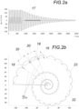
- the invention is based on the knowledge that in the event of a transient decay process, the synchronous zero voltage vectors form a logarithmic spiral in the complex image plane, so that the angular velocity of the synchronous zero voltage vectors as well as the logarithmic damping of the magnitude of the synchronous zero voltage vectors are largely constant during the decay process.
- the angular velocity of the vectorial difference between two synchronous zero voltage vectors and the rate of change of the attenuation of the vectorial difference between two synchronous zero voltage vectors are largely constant during the decay process and allow conclusions to be drawn about the rates of change of the angular velocity and the magnitude of the synchronous zero voltage vector and thus also of the zero voltage vector itself.
- the network parameters for controlling the Petersen coil can be reliably determined by averaging within a network period, in particular within half a network period, after a multiple of the specified time intervals, provided that the significant interference influences on the transformation in the complex image area have subsided.
- the transformation into the complex image area can, for example, be a discrete Fourier transformation.
- the computing unit can transfer the deviation of the angle of the vectorial difference between two time steps as the angular velocity deviation of the zero voltage vector from the reference angular velocity and / or the absolute value deviation of the vectorial differences between two time steps as the damping of the zero voltage vector as a network parameter to a controller for the Petersen coil in order to control the parallel resonant circuit true that a capacitive ground fault current can be compensated.
- the resource expenditure for carrying out the method according to the invention on a computing unit can be reduced if, as described above, the predetermined time interval is the time interval between two minima or maxima of the magnitude of the synchronous zero voltage vector.
- an additional impedance can, for example, be connected between the star point of the power network and earth for a predetermined period of time. This period can be at least half a period of the nominal frequency.
- the star point can alternatively be connected to a voltage source via the additional impedance.
- the modulation current pulse can have different signal forms, such as an approximate Dirac pulse, an alternating signal with nominal frequency or an alternating signal with multiple and/or varying frequency components.
- the modulation current pulse can be fed into the zero system, for example, at the star point of the multi-phase power network, with feeding possible both in front of the Petersen coil and between the Petersen coil and the star point.
- the energy required to feed in the modulation current pulse can be considerable, so that, especially in power networks with natural asymmetry, it is advisable to short-circuit the star point to earth via a current-limiting impedance in order to apply a modulation current pulse to the zero system.
- the method according to the invention therefore has the advantage that external Petersen coils can also be taken into account, since these influence the zero voltage in the decay process and their switching on and off can therefore be recognized.
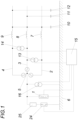
- the parameters for a Petersen coil 1 for a power network with three conductors 2, 3, 4 are determined.
- the Petersen coil 1 is connected between the star point 5 of the star connection of the three conductors 2, 3, 4 and the earth 6 to form a parallel resonant circuit made up of the Petersen coil 1 and the inductors 7, 8, 9 and the earth capacitances 10, 11 , 12 to form the conductors 2, 3, 4.
- the ohmic line resistances are not shown.
- Voltage converters 13, 14 allow the interlinked voltage between the individual phases 2, 3, 4 to be determined and can sample the interlinked voltage over a period of the nominal frequency and forward these sampled values to a computing unit 15.
- a voltage converter 16 is provided which detects and samples the zero voltage between the star point 5 and the earth 6 and directs the sampled zero voltage signal 17 to the computing unit 15.
- the zero voltage signal 17 shown is sampled over a period of the nominal frequency of the power network and transformed into the complex image area by the computing unit 15 as a zero voltage pointer U 0 in the decay process.
- the angular velocity of this zero voltage pointer U 0 is then reduced by a reference angular velocity ⁇ N and thereby the Synchronous zero voltage pointer U 0 S formed.
- This reference angular velocity ⁇ N can be derived either from the nominal frequency or from the frequency of the linked voltage signal between two phases 2, 3, 4.
- the zero voltage signal 17 is sampled per time step, transformed into the complex image area as a zero voltage pointer U 0 and a synchronous zero voltage pointer U 0 S is formed therefrom.
- the vectorial difference 18 is then formed between the synchronous zero voltage pointer U 0 S of this time step and a synchronous zero voltage pointer U 0 S of a previous time step, preferably the immediately preceding time step.
- the computing unit 15 can temporarily store at least one synchronous zero voltage pointer U 0 S from a previous time step.
- the angular deviation 19 between the vector differences 18 of two time steps can then be determined and output as the angular velocity deviation ⁇ of the zero voltage pointer U 0 from the reference angular velocity ⁇ N.
- the magnitude deviation between the magnitudes 20 of the vector differences 18 of two time steps can also be determined and output as attenuation of the zero voltage vector U 0 and thus also of the synchronous voltage vector U 0 S.
- the time course of the logarithm of the amount 21 is for the in the Fig. 2b illustrated case in the Fig. 3a shown, where the slope of this curve corresponds to the attenuation.
- an angular deviation 19 and an amount deviation between the amounts 20 are determined for each time step, with vectorial differences 18 of two immediately successive time steps being used for the calculation. This means that only one must be in the computing unit 15 Synchronous zero voltage pointer U 0 S of the previous time step and a vector difference 18 of the previous time step are buffered, which enables extremely low resource consumption.
- the vector differences 18 approximately form a logarithmic spiral 22, the time course of the individual synchronous zero voltage pointers U 0 S being indicated by a connecting line 23.
- the angle of this synchronous zero voltage pointer U 0 S is for the in the Fig. 2b
- the slope of this curve corresponds to the angular velocity deviation and is ⁇ .
- Figs. 2a to 3b refer to the case without natural asymmetry
- the logarithmic spiral 22 is shifted away from the zero point.
- the measures according to the invention do not change the determination of the network parameters. By forming the vector differences 18, the asymmetrical signal component is eliminated.
- the zero system is subjected to a modulation current pulse, after which the zero voltage signal is sampled in the decay process to determine the zero voltage pointer U 0 and that The method according to the invention is carried out further as described above.
Description
Die Erfindung bezieht sich auf ein Verfahren zur Ermittlung von Netzparametern zur Regelung einer Petersen-Spule zur Erdschlusskompensation eines mehrphasigen Stromnetzes mit einer Nennfrequenz, wobei ein Nullspannungssignal erfasst wird.The invention relates to a method for determining network parameters for controlling a Petersen coil for earth fault compensation of a multi-phase power network with a nominal frequency, wherein a zero voltage signal is detected.
In einem gelöschten oder isolierten Stromnetz fließen aufgrund der Leiter-Erdkapazitäten im Falle eines Erdschlusses hohe Ströme zwischen der Erde und dem erdschlussbehafteten Leiter. Ein Erdschluss führt somit nicht nur zu einer Störung des Stromnetzes, sondern auch zu einem hohen Gefährdungspotential am Ort des Erdschlusses. Aus dem Stand der Technik ist es daher bekannt, Petersen-Spulen einzusetzen, die den kapazitiven Erdschlussstrom kompensieren, indem sie einen Parallelschwingkreis bilden, der den Strom über die Erdschlussstelle minimiert. Dadurch wird die Gefahr eines Stromunfalls gesenkt und das erdschlussbehaftete Netz kann trotz des Erdschlusses weiterbetrieben werden. Um den Parallelschwingkreis der Petersen-Spule auf die Leitungskapazitäten anzupassen, muss allerdings die Eigenfrequenz des zu kompensierenden Schwingkreises bekannt sein.In an extinguished or isolated power system, high currents flow between the earth and the ground-faulted conductor due to the conductor-earth capacitances in the event of a ground fault. A ground fault not only leads to a disruption in the power grid, but also to a high risk potential at the location of the ground fault. It is therefore known from the prior art to use Petersen coils that compensate for the capacitive ground fault current by forming a parallel resonant circuit that minimizes the current across the ground fault point. This reduces the risk of an electrical accident and the network affected by a ground fault can continue to operate despite the ground fault. In order to adapt the parallel resonant circuit of the Petersen coil to the line capacities, the natural frequency of the resonant circuit to be compensated must be known.
Die Regelung der Petersen-Spule ist eine Präventivmaßnahme für den Fall des Erdschlusses und soll im gesunden Netzzustand durchgeführt werden. Die Zunahme der Vermaschung der Stromnetze und immer häufigeres Redispatchen machen ein häufiges Nachregeln erforderlich.The control of the Petersen coil is a preventive measure in the event of a ground fault and should be carried out in a healthy network condition. The increase in the interconnection of power grids and increasingly frequent redispatching make frequent readjustments necessary.
Zur Ermittlung der Eigenfrequenz schlägt die
Nachteilig am Stand der Technik ist einerseits, dass eine Ermittlung der Abstimmung erst nach einem Erdschluss erfolgen kann und bei Auftreten einer natürlichen Unsymmetrie nicht mehr angewandt werden kann, da naturgemäß die zum Ausschwingvorgang gehörenden Nulldurchgänge nicht mehr bestimmt werden können.The disadvantage of the prior art is, on the one hand, that the tuning can only be determined after a ground fault and can no longer be used if a natural asymmetry occurs, since the zero crossings associated with the decay process can naturally no longer be determined.
Um die Eigenfrequenz dennoch ermitteln zu können, schlägt die
Nachteilig daran ist allerdings, dass dieses Verfahren zeitaufwändig ist, da die Einschwingzeit der jeweiligen Frequenz abgewartet werden muss. Es muss außerdem für jede Frequenzkomponente die Admittanz und Leitfähigkeit ermittelt werden, ob der Schwingkreis bei dieser Frequenz über- oder unterkompensiert ist, weswegen eine Vielzahl an möglichen Frequenzen evaluiert werden muss.The disadvantage, however, is that this method is time-consuming because you have to wait for the settling time of the respective frequency. The admittance and conductivity must also be determined for each frequency component to determine whether the resonant circuit is over- or under-compensated at this frequency, which is why a large number of possible frequencies must be evaluated.
Weitere Verfahren zur Ermittlung von Netzparametern und zur Regelung einer Petersen-Spule sind aus
Der Erfindung liegt somit die Aufgabe zugrunde, ein Verfahren zur Ermittlung von Netzparametern zur Erdschlusskompensation bereitzustellen, bei dem selbst bei auftretender natürlicher Unsymmetrie die Netzparameter für eine Petersen-Spule zuverlässig innerhalb einer Periode der Netzfrequenz festgestellt werden können.The invention is therefore based on the object of providing a method for determining network parameters for earth fault compensation, in which the network parameters for a Petersen coil can be reliably determined within a period of the network frequency even if natural asymmetry occurs.
Die Erfindung, die vom Verfahrensanspruch 1 definiert wird, löst die gestellte Aufgabe dadurch, dass das kontinuierliche Nullspannungssignal bei einem transienten Ausschwingvorgang über eine Periode der Nennfrequenz abgetastet und je Zeitschritt als Nullspannungszeiger in den komplexen Bildbereich transformiert wird, wonach je Zeitschritt durch Verminderung der Winkelgeschwindigkeit des Nullspannungszeigers um eine Referenzwinkelgeschwindigkeit ein Synchronnullspannungszeiger gebildet und je Zeitschritt die vektorielle Differenz zwischen zwei Synchronnullspannungszeigern mit vorgegebenem Zeitabstand bestimmt wird, wonach die Winkelabweichung zwischen den vektoriellen Differenzen zweier Zeitschritte als Winkelgeschwindigkeitsabweichung des Nullspannungszeigers von der Referenzwinkelgeschwindigkeit und/oder die Betragsabweichung der vektoriellen Differenzen zweier Zeitschritte als Dämpfung des Nullspannungszeigers ausgegeben wird. Ein transienter Ausschwingvorgang kann beispielsweise durch einen erstmaligen oder wiederzündenden Erdschluss einer Phase hervorgerufen werden, oder über eine Einspeisung eines Modulationsstroms erfolgen. Die Abtastung des Nullspannungssignals erfolgt vorzugsweise mit einem ganzzahligen Vielfachen der Nennfrequenz des Stromnetzes und kann beispielsweise über einen Analog-Digital-Wandler erfolgen, der die Abtastwerte an eine Recheneinheit weiterleitet. Diese Recheneinheit transformiert das Nullspannungssignal anhand der Abtastwerte in den komplexen Bildbereich. Die dabei je Zeitschritt gebildeten Zeiger werden als Nullspannungszeiger bezeichnet. Daraufhin wird die Winkelgeschwindigkeit der Nullspannungszeiger um eine Referenzwinkelgeschwindigkeit unter Ausbildung von Synchronnullspannungszeigern vermindert. Diese Referenzwinkelgeschwindigkeit kann beispielsweise die zur Nennfrequenz korrespondierende Winkelgeschwindigkeit sein. In einer bevorzugten Ausführungsform der Erfindung wird das verkettete Spannungssignal zwischen zwei Leitern abgetastet, ebenso transformiert und dessen Winkelgeschwindigkeit als Referenzwinkelgeschwindigkeit herangezogen. Darüber hinaus erleichtert die so reduzierte Winkelgeschwindigkeit des Synchronnullspannungszeigers die folgende Ermittlung der Netzparameter aus der Änderungsrate von Betrag und Winkel der vektoriellen Differenz zwischen zwei Synchronnullspannungszeigern mit vorgegebenem Zeitabstand. Dieser Zeitabstand kann fest vorgegeben sein. Da sich aber die Frequenz und folglich die Winkelgeschwindigkeit der Nullspannung von der Nennfrequenz unterscheiden kann, kann es bei der Transformation in den komplexen Bildbereich zu Leck-Effekten kommen, die sich in lokalen Minima und Maxima des Betrags des Nullspannungszeigers und in weiterer Folge im Betrag und Winkel des Synchronnullspannungszeigers manifestieren. Diese sich aus der Transformation in den komplexen Bildbereich ergebenden Störungen können entweder mittels eines zu bestimmenden Korrekturfaktors ausgeglichen werden, oder der Zeitabstand zwischen zwei Synchronnullspannungszeigern, die für die Bestimmung der vektoriellen Differenz herangezogen werden, wird so gewählt, dass die herangezogenen Synchronnullspannungszeiger mit lokalen Minima oder Maxima des Betrags des Synchronnullspannungszeigers zusammenfallen. In letzterem Fall entspricht der Zeitabstand also dem zeitlichen Abstand zwischen zwei Minima oder Maxima des Betrags des Synchronnullspannungszeigers. Durch die Bildung der vektoriellen Differenz zwischen zwei Synchronnullspannungszeigern, die einen vorgegebenen zeitlichen Abstand zueinander haben, kann ein sich durch eine natürliche Unsymmetrie ergebender Signalanteil entfernt werden, weil die natürliche Unsymmetrie die beiden Synchronnullspannungszeiger gleichermaßen beeinflusst. Der Nullspannungszeiger setzt sich nämlich aus zwei Komponenten zusammen, wovon eine ( U N ) mit der Nennfrequenz schwingt und eine ( U ab ) den abklingenden Spannungsanteil des Ausschwingvorgangs repräsentiert. Diese beiden Komponenten können durch folgende Gleichungen beschrieben werden ![]()
![]()
![]()
![]()
Der Nullspannungszeiger U 0 ist daher folglich U N + U ab, also ![]()
![]()
Mathematisch kann nun der Synchronnullspannungszeiger U 0S folgendermaßen gebildet werden ![]()
![]()
![]()
![]()
Dabei sind UN und Uab die Amplituden des Nennspannungsanteils bzw. der abklingenden Spannung, ωN und ωab die Winkelgeschwindigkeit des Nennspannungsanteils bzw. des abklingenden Anteils, t die Zeit und j die imaginäre Einheit. λ ist die (reale) Zeitkonstante des Abklingvorgangs, Δω ist die Differenz zwischen ωab und ωN und ϕ 0 die Phasenverschiebung. Durch die Bildung der vektoriellen Differenz fällt der zeitlich konstante Teil UN weg, wodurch die natürliche Unsymmetrie die Ermittlung der Winkelgeschwindigkeitsabweichung und der Dämpfung als Netzparameter nicht behindert. Der Erfindung liegt die Erkenntnis zu Grunde, dass die Synchronnullspannungszeiger im Falle eines transienten Ausschwingvorgangs in der komplexen Bildebene eine logarithmische Spirale bilden, sodass die Winkelgeschwindigkeit der Synchronnullspannungszeiger genauso wie die logarithmische Dämpfung des Betrags der Synchronnullspannungszeiger während des Ausschwingvorgangs weitgehend konstant sind. Somit sind auch die Winkelgeschwindigkeit der vektoriellen Differenz zwischen zwei Synchronnullspannungszeigern und die Änderungsrate der Dämpfung der vektoriellen Differenz zwischen zwei Synchronnullspannungszeigern während des Ausschwingvorgangs weitgehend konstant und erlauben einen Rückschluss auf die Änderungsraten der Winkelgeschwindigkeit und des Betrags des Synchronnullspannungszeigers und damit auch des Nullspannungszeigers selbst. Aufgrund der konstanten Winkelgeschwindigkeit und der konstanten Änderungsrate der Dämpfung während des Ausschwingvorgangs können die Netzparameter zur Regelung der Petersen-Spule innerhalb einer Netzperiode insbesondere innerhalb einer halben Netzperiode nach einem Vielfachen der vorgegebenen Zeitabstände durch Mittelung zuverlässig bestimmt werden, vorausgesetzt, dass die maßgeblichen Störeinflüsse auf die Transformation in den komplexen Bildbereich abgeklungen sind. Bei der Transformation in den komplexen Bildbereich kann es sich beispielsweise um eine diskrete Fourier-Transformation handeln. Als zusätzlicher Vorteil ergibt sich, dass zu Beginn des Ausschwingvorgangs die Signalamplituden verhältnismäßig groß sind, sodass das daraus resultierende hohe Signal-zu-Rausch-Verhältnis die zuverlässige Bestimmung der Netzparameter begünstigt. Die Recheneinheit kann die Abweichung des Winkels der vektoriellen Differenz zweier Zeitschritte als Winkelgeschwindigkeitsabweichung des Nullspannungszeigers von der Referenzwinkelgeschwindigkeit und/oder die Betragsabweichung der vektoriellen Differenzen zweier Zeitschritte als Dämpfung des Nullspannungszeigers als Netzparameter an einen Regler für die Petersen-Spule übergeben, um den Parallelschwingkreis so zu stimmen, dass ein kapazitiver Erdschlussstrom kompensiert werden kann.Here U N and U ab are the amplitudes of the nominal voltage component or the decaying voltage, ω N and ω ab are the angular velocity of the nominal voltage component or the decaying component, t is the time and j is the imaginary unit. λ is the (real) time constant of the decay process, Δω is the difference between ω ab and ω N and ϕ 0 is the phase shift. By forming the vectorial difference, the time-constant part U N is eliminated, so that the natural asymmetry does not hinder the determination of the angular velocity deviation and the damping as network parameters. The invention is based on the knowledge that in the event of a transient decay process, the synchronous zero voltage vectors form a logarithmic spiral in the complex image plane, so that the angular velocity of the synchronous zero voltage vectors as well as the logarithmic damping of the magnitude of the synchronous zero voltage vectors are largely constant during the decay process. Thus, the angular velocity of the vectorial difference between two synchronous zero voltage vectors and the rate of change of the attenuation of the vectorial difference between two synchronous zero voltage vectors are largely constant during the decay process and allow conclusions to be drawn about the rates of change of the angular velocity and the magnitude of the synchronous zero voltage vector and thus also of the zero voltage vector itself. Due to the constant angular velocity and the constant rate of change of the damping during the decay process, the network parameters for controlling the Petersen coil can be reliably determined by averaging within a network period, in particular within half a network period, after a multiple of the specified time intervals, provided that the significant interference influences on the transformation in the complex image area have subsided. The transformation into the complex image area can, for example, be a discrete Fourier transformation. As An additional advantage is that at the beginning of the decay process the signal amplitudes are relatively large, so that the resulting high signal-to-noise ratio promotes the reliable determination of the network parameters. The computing unit can transfer the deviation of the angle of the vectorial difference between two time steps as the angular velocity deviation of the zero voltage vector from the reference angular velocity and / or the absolute value deviation of the vectorial differences between two time steps as the damping of the zero voltage vector as a network parameter to a controller for the Petersen coil in order to control the parallel resonant circuit true that a capacitive ground fault current can be compensated.
Der Ressourcenaufwand zur Durchführung des erfindungsgemäßen Verfahrens auf einer Recheneinheit kann reduziert werden, wenn wie oben beschrieben, der vorgegebene Zeitabstand der zeitliche Abstand zwischen zwei Minima oder Maxima des Betrags des Synchronnullspannungszeigers ist. Zufolge dieser Maßnahmen kann der Einfluss einer Frequenzabweichung bei der Transformation in den komplexen Bildbereich in einfacher Weise ausgeglichen werden, ohne dass Korrekturfaktoren bestimmen werden müssen.The resource expenditure for carrying out the method according to the invention on a computing unit can be reduced if, as described above, the predetermined time interval is the time interval between two minima or maxima of the magnitude of the synchronous zero voltage vector. As a result of these measures, the influence of a frequency deviation during the transformation into the complex image area can be easily compensated for without having to determine correction factors.
Um die Netzparameter zur Regelung einer Petersen-Spule bereits im gesunden Betrieb vor Eintreten eines Erdschlusses zu bestimmen, empfiehlt es sich, dass das Nullsystem mit einem Modulationsstromimpuls beaufschlagt wird, wonach im Abklingvorgang das Nullspannungssignal zur Bestimmung des Nullspannungszeigers abgetastet wird. Zur Beaufschlagung mit einem Modulationsstromimpuls kann beispielsweise eine zusätzliche Impedanz für einen vorgegebenen Zeitraum zwischen Sternpunkt des Stromnetzes und Erde geschaltet werden. Dieser Zeitraum kann wenigstens eine halbe Periode der Nennfrequenz betragen. Im Falle eines symmetrischen Netzes mit geringer oder keiner Nullspannung kann der Sternpunkt über die zusätzliche Impedanz alternativ mit einer Spannungsquelle verbunden werden. Der Modulationsstromimpuls kann dabei unterschiedliche Signalformen aufweisen, wie beispielsweise die eines angenäherten Dirac-Pulses, eines Wechselsignals mit Nennfrequenz oder eines Wechselsignals mit mehreren und/oder variierenden Frequenzanteilen. Die Einspeisung des Modulationsstromimpulses in das Nullsystem kann beispielsweise am Sternpunkt des mehrphasigen Stromnetzes erfolgen, wobei eine Einspeisung sowohl vor der Petersen-Spule, als auch zwischen Petersen-Spule und Sternpunkt möglich ist.In order to determine the network parameters for controlling a Petersen coil in healthy operation before an earth fault occurs, it is recommended that the zero system is subjected to a modulation current pulse, after which the zero voltage signal is sampled during the decay process to determine the zero voltage pointer. To apply a modulation current pulse, an additional impedance can, for example, be connected between the star point of the power network and earth for a predetermined period of time. This period can be at least half a period of the nominal frequency. In the case of a symmetrical network with little or no zero voltage, the star point can alternatively be connected to a voltage source via the additional impedance. The modulation current pulse can have different signal forms, such as an approximate Dirac pulse, an alternating signal with nominal frequency or an alternating signal with multiple and/or varying frequency components. The modulation current pulse can be fed into the zero system, for example, at the star point of the multi-phase power network, with feeding possible both in front of the Petersen coil and between the Petersen coil and the star point.
Gerade bei großen Stromnetzen kann die für die Einspeisung des Modulationsstromimpulses erforderliche Energie beträchtlich sein, sodass es sich gerade bei Stromnetzen mit natürlicher Unsymmetrie empfiehlt, zur Beaufschlagung des Nullsystems mit einem Modulationsstromimpuls den Sternpunkt über eine strombegrenzende Impedanz gegen Erde kurzzuschließen.Especially in large power networks, the energy required to feed in the modulation current pulse can be considerable, so that, especially in power networks with natural asymmetry, it is advisable to short-circuit the star point to earth via a current-limiting impedance in order to apply a modulation current pulse to the zero system.
Das erfindungsgemäße Verfahren hat somit den Vorteil, dass auch externe Petersen-Spulen berücksichtigt werden können, da diese die Nullspannung im Ausschwingvorgang mitbeeinflussen und somit deren Zu- und Abschalten erkannt werden kann.The method according to the invention therefore has the advantage that external Petersen coils can also be taken into account, since these influence the zero voltage in the decay process and their switching on and off can therefore be recognized.
In der Zeichnung ist der Erfindungsgegenstand beispielsweise dargestellt. Es zeigen
- Fig. 1
- ein schematisches Blockschaltbild eines dreiphasigen Stromnetzes mit einer Petersen-Spule,
- Fig. 2a
- den zeitlichen Spannungs- und Stromverlauf des Nullspannungssignals während eines transienten Ausschwingvorgangs ohne natürlicher Unsymmetrie,
- Fig. 2b
- einen der
Fig. 2a entsprechenden Synchronnullspannungszeiger in der komplexen Ebene, - Fig. 3a
- den zeitlichen Verlauf des absoluten Betrags des Synchronnullspannungszeigers der
Fig. 2b , - Fig. 3b
- der zeitliche Verlauf des Winkels des Synchronspannungszeigers der
Fig 2b , - Fig. 4a
- den zeitlichen Spannungs- und Stromverlauf des Nullspannungssignals während eines transienten Ausschwingvorgangs mit natürlicher Unsymmetrie,
- Fig. 4b
- einen der
Fig. 4a entsprechenden Synchronnullspannungszeiger in der komplexen Ebene, - Fig. 5a
- den zeitlichen Spannungs- und Stromverlauf des Nullspannungssignals bei Beaufschlagung mit einem Modulationsstromimpuls mit natürlicher Unsymmetrie und
- Fig. 5b
- einen der
Fig. 5a entsprechenden Synchronnullspannungszeiger in der komplexen Ebene.
- Fig. 1
- a schematic block diagram of a three-phase power system with a Petersen coil,
- Fig. 2a
- the time curve of the voltage and current of the zero voltage signal during a transient decay process without natural asymmetry,
- Fig. 2b
- one of the
Fig. 2a corresponding synchronous zero voltage pointer in the complex plane, - Fig. 3a
- the time course of the absolute value of the synchronous zero voltage pointer
Fig. 2b , - Fig. 3b
- the time course of the angle of the synchronous voltage pointer
Fig 2b , - Fig. 4a
- the time curve of the voltage and current of the zero voltage signal during a transient decay process with natural asymmetry,
- Fig. 4b
- one of the
Fig. 4a corresponding synchronous zero voltage pointer in the complex plane, - Fig. 5a
- the temporal voltage and current curve of the zero voltage signal when subjected to a modulation current pulse with natural asymmetry and
- Fig. 5b
- one of the
Fig. 5a corresponding synchronous zero voltage pointer in the complex plane.
Bei einem erfindungsgemäßen Verfahren werden die Parameter für eine Petersen-Spule 1 für ein Stromnetz mit drei Leitern 2, 3, 4 ermittelt. Die Petersen-Spule 1 ist dabei zwischen dem Sternpunkt 5 der Sternschaltung der drei Leiter 2, 3, 4 und der Erde 6 geschaltet, um einen Parallelschwingkreis aus der Petersen-Spule 1 und den Induktivitäten 7, 8, 9 und den Erdkapazitäten 10, 11, 12 der Leiter 2, 3, 4 zu bilden. Auf die Darstellung der ohm'schen Leitungswiderstände wurde aus Übersichtlichkeitsgründen verzichtet. Spannungswandler 13, 14 erlauben die Bestimmung der verketteten Spannung zwischen den einzelnen Phasen 2, 3, 4 und können die verkettete Spannung über eine Periode der Nennfrequenz abtasten und diese Abtastwerte an eine Recheneinheit 15 leiten. Darüber hinaus ist ein Spannungswandler 16 vorgesehen, der die Nullspannung zwischen dem Sternpunkt 5 und der Erde 6 erfasst, abtastet und das abgetastete Nullspannungssignal 17 an die Recheneinheit 15 leitet.In a method according to the invention, the parameters for a
Während eines transienten Ausschwingvorganges wird das beispielsweise für einen Fall ohne natürliche Unsymmetrie in der
In einer bevorzugten Ausführungsform wird je Zeitschritt das Nullspannungssignal 17 abgetastet, als Nullspannungszeiger U 0 in den komplexen Bildbereich transformiert und daraus ein Synchronnullspannungszeiger U 0S gebildet. Für jeden Zeitschritt wird sodann die vektorielle Differenz 18 zwischen dem Synchronnullspannungszeiger U 0S dieses Zeitschritts und eines Synchronnullspannungszeigers U 0S eines vorangegangenen Zeitschritts, vorzugsweise des unmittelbar vorangegangenen Zeitschrittes gebildet. Zu diesem Zweck kann die Recheneinheit 15 wenigstens einen Synchronnullspannungszeiger U 0S eines vorangegangenen Zeitschritts zwischenspeichern.In a preferred embodiment, the zero
Sodann kann die Winkelabweichung 19 zwischen den vektoriellen Differenzen 18 zweier Zeitschritte bestimmt und als Winkelgeschwindigkeitsabweichung Δω des Nullspannungszeigers U 0 von der Referenzwinkelgeschwindigkeit ωN ausgegeben werden.The
Ebenfalls kann die Betragsabweichung zwischen den Beträgen 20 der vektoriellen Differenzen 18 zweier Zeitschritte bestimmt und als Dämpfung des Nullspannungszeigers U 0 und somit auch des Synchronspannungszeigers U 0S ausgegeben werden. Der zeitliche Verlauf des Logarithmus des Betrags 21 ist für den in der
In einer bevorzugten Ausführungsform wird für jeden Zeitschritt eine Winkelabweichung 19 und eine Betragsabweichung zwischen den Beträgen 20 bestimmt, wobei jeweils vektorielle Differenzen 18 zweier unmittelbar aufeinanderfolgender Zeitschritte für die Berechnung herangezogen werden. Somit müssen in der Recheneinheit 15 jeweils nur ein Synchronnullspannungszeiger U 0S des vorangegangenen Zeitschritts sowie eine vektorielle Differenz 18 des vorangegangenen Zeitschritts zwischengespeichert werden, was einen äußerst geringen Ressourcenverbrauch ermöglicht.In a preferred embodiment, an
Bei wiederholter Anwendung des erfindungsgemäßen Verfahrens bilden die vektoriellen Differenzen 18 näherungsweise eine logarithmische Spirale 22, wobei der zeitliche Verlauf der einzelnen Synchronnullspannungszeiger U 0S durch eine Verbindungslinie 23 angedeutet wird.When the method according to the invention is used repeatedly, the
Der Winkel dieser Synchronnullspannungszeiger U 0S ist für den in der
Um für die Bestimmung der Netzparameter nicht erst einen Störfall abwarten zu müssen, der einen transienten Ausschwingvorgang der Nullspannung zufolge hat, wird erfindungsgemäß vorgeschlagen, dass das Nullsystem mit einem Modulationsstromimpuls beaufschlagt wird, wonach im Abklingvorgang das Nullspannungssignal zur Bestimmung des Nullspannungszeigers U 0 abgetastet und das erfindungsgemäße Verfahren wie oben beschrieben weiter durchgeführt wird.In order not to have to wait for a fault to determine the network parameters, which results in a transient decay of the zero voltage, it is proposed according to the invention that the zero system is subjected to a modulation current pulse, after which the zero voltage signal is sampled in the decay process to determine the zero voltage pointer U 0 and that The method according to the invention is carried out further as described above.
Zur Einspeisung des Modulationsstromimpulses können unterschiedliche Maßnahmen gesetzt werden. Besonders einfache Bedingungen ergeben sich aber, wenn der Sternpunkt 5 über einen Leistungsschalter 24 durch die Recheneinheit 15 gegen Erde 6 kurzfristig über eine strombegrenzende Impedanz 25 kurzgeschlossen werden kann. Durch einen solchen Modulationsstromimpuls wird das Nullsystem angeregt und es stellt sich nach dem Ende des Modulationsstromimpulses ein Abklingvorgang ein, der zur Durchführung des erfindungsgemäßen Verfahrens erforderlich ist. Die Nullspannung und ein den
Claims (4)
- Method for determining power grid parameters for controlling a Petersen coil (1) for earth fault compensation of a polyphase power grid with a nominal frequency, wherein a zero-sequence voltage signal (17) is detected, wherein the continuous zero-sequence voltage (17) is sampled during a transient decay process over a period of the nominal frequency and is transformed per time step as zero-sequence voltage pointer U 0 into the complex image area, characterized in that for each time step, by reducing the angular velocity of the zero-sequence voltage pointer U 0 by a reference angular velocity ωN a synchronous zero-sequence voltage pointer U 0S is formed per time step by reducing the angular velocity of the zero-sequence voltage pointer by a reference angular velocity, and the vectorial difference (18) between two synchronous zero-sequence voltage pointers U 0S is determined with a predetermined time interval, whereafter the angular deviation (19) between the vectorial differences (18) of two time steps is determined as angular velocity deviation of the zero-sequence voltage pointer U 0from the reference angular velocity ωN and/or the amount deviation of the vectorial differences (18) of two time steps as damping of the zero-sequence voltage pointer U 0 is output.
- The method according to claim 1, characterized in that the predetermined time interval is the time interval between two minima or maxima of the magnitude of the synchronous zero-sequence voltage pointer U 0S .
- Method according to claim 1 or 2, characterized in that a modulation current pulse is applied to the zero-sequence system, whereafter, in the decay process, the zero-sequence voltage signal (17) is sampled to determine the zero-sequence voltage vector U 0.
- The method according to claim 3, characterized in that for applying a modulation current pulse to the zero-sequence system, the neutral point (5) is short-circuited to ground (6) via a current-limiting impedance (25).
Applications Claiming Priority (1)
| Application Number | Priority Date | Filing Date | Title |
|---|---|---|---|
| ATA50440/2021A AT524958B1 (en) | 2021-06-01 | 2021-06-01 | Procedure for determining network parameters for controlling a Petersen coil |
Publications (3)
| Publication Number | Publication Date |
|---|---|
| EP4099531A1 EP4099531A1 (en) | 2022-12-07 |
| EP4099531B1 true EP4099531B1 (en) | 2023-12-13 |
| EP4099531C0 EP4099531C0 (en) | 2023-12-13 |
Family
ID=81260039
Family Applications (1)
| Application Number | Title | Priority Date | Filing Date |
|---|---|---|---|
| EP22168172.9A Active EP4099531B1 (en) | 2021-06-01 | 2022-04-13 | Method for determining network parameters for controlling a petersen coil |
Country Status (2)
| Country | Link |
|---|---|
| EP (1) | EP4099531B1 (en) |
| AT (1) | AT524958B1 (en) |
Family Cites Families (8)
| Publication number | Priority date | Publication date | Assignee | Title |
|---|---|---|---|---|
| FR2697341B1 (en) * | 1992-10-26 | 1995-01-13 | Electricite De France | Method and device for measuring the agreement and the disagreement of compensation of an electrical distribution network. |
| FI113592B (en) * | 1997-08-27 | 2004-05-14 | Abb Oy | A method for adjusting a compensating choke in a power distribution network |
| DE10307668B3 (en) * | 2003-02-21 | 2005-01-13 | Edc Gmbh | Determining parameters of Petersen-coil compensated network without de-tuning the coils, by feeding composite current into zero-phase system, and measuring voltages |
| DE502004001266D1 (en) * | 2004-05-18 | 2006-10-05 | Trench Austria Gmbh | Method for displaying a high-ohm ground fault in a three-phase network |
| AT504506B1 (en) | 2007-04-03 | 2008-06-15 | Univ Graz Tech | Discharge coil adjusting method for use in electrical energy networks, involves determining difference between value of disgruntlement and desired value of disgruntlement available for network, and adjusting coil according to difference |
| EP2260556B1 (en) * | 2008-04-03 | 2015-10-14 | Siemens Aktiengesellschaft | Method and arrangement for generating an error signal |
| CZ308721B6 (en) | 2014-08-28 | 2021-03-24 | Ege, Spol.S R.O. | Method and device for automatically adjusting continuously and/or discretely tunable quenching chokes in the compensated network of the electrical system |
| EP3657620B1 (en) * | 2018-11-21 | 2021-08-18 | ABB Schweiz AG | Method and apparatus for controlling arc suppression device |
-
2021
- 2021-06-01 AT ATA50440/2021A patent/AT524958B1/en active
-
2022
- 2022-04-13 EP EP22168172.9A patent/EP4099531B1/en active Active
Also Published As
| Publication number | Publication date |
|---|---|
| EP4099531A1 (en) | 2022-12-07 |
| AT524958B1 (en) | 2022-11-15 |
| EP4099531C0 (en) | 2023-12-13 |
| AT524958A4 (en) | 2022-11-15 |
Similar Documents
| Publication | Publication Date | Title |
|---|---|---|
| EP3198698B1 (en) | Differential protection method and differential protection device for performing a differential protection method | |
| EP2260556B1 (en) | Method and arrangement for generating an error signal | |
| EP3531141B1 (en) | Method and device for network condition monitoring | |
| DE2805524C2 (en) | ||
| EP0993695B1 (en) | Method and system for detecting short-circuits in low-voltage mains | |
| EP1844484B1 (en) | Method and device for determining a switching time of an electric switching device | |
| EP3417523B1 (en) | Method for controlling a variable transformer and electrical system for coupling two ac networks | |
| CH665735A5 (en) | METHOD FOR DETECTION OF AN ERROR POINT IN A transmission line. | |
| DE102011084910A1 (en) | Method and device for feeding electrical current into an electrical network | |
| EP3046197A1 (en) | Method and device for detecting the earth fault direction in a three phase alternating electric current network | |
| EP0150814B1 (en) | Digital impedance relay | |
| DE2609654A1 (en) | DIGITAL OVERCURRENT RELEASE | |
| EP0812427B1 (en) | Unipolar earth leakage recognition process for three phase mains | |
| DE10302451B3 (en) | Earthing connection recognition method for 3-phase network using evaluation of charge curve obtained by integration of current from voltage zero transition and zero voltage limit value point | |
| EP4099531B1 (en) | Method for determining network parameters for controlling a petersen coil | |
| DE102020114018A1 (en) | Method and device for determining the direction to an earth fault | |
| DE102021112016B3 (en) | Method and device for determining a ground fault direction | |
| EP3916939A1 (en) | Method for line protection and protection arrangement | |
| EP2908397B1 (en) | Method for protecting an electrical supply network | |
| DE4026799A1 (en) | Selective detection of faults in conductors in high voltage network - by comparing conductor voltages and currents with earth current and star earth voltage | |
| DE10307668B3 (en) | Determining parameters of Petersen-coil compensated network without de-tuning the coils, by feeding composite current into zero-phase system, and measuring voltages | |
| DE4418124A1 (en) | Device for recognising insulation deterioration on power-supply cables | |
| DE10225058B4 (en) | Method for the selective detection of earth fault wipers in three-phase networks | |
| WO2020094866A1 (en) | Measuring device and method for measuring electrical variables in a three-phase alternating current network | |
| EP3923435A1 (en) | Method and device for monitoring a compensated three-phase current network for a change in the tuning of the arc suppression coil |
Legal Events
| Date | Code | Title | Description |
|---|---|---|---|
| PUAI | Public reference made under article 153(3) epc to a published international application that has entered the european phase |
Free format text: ORIGINAL CODE: 0009012 |
|
| STAA | Information on the status of an ep patent application or granted ep patent |
Free format text: STATUS: THE APPLICATION HAS BEEN PUBLISHED |
|
| AK | Designated contracting states |
Kind code of ref document: A1 Designated state(s): AL AT BE BG CH CY CZ DE DK EE ES FI FR GB GR HR HU IE IS IT LI LT LU LV MC MK MT NL NO PL PT RO RS SE SI SK SM TR |
|
| STAA | Information on the status of an ep patent application or granted ep patent |
Free format text: STATUS: REQUEST FOR EXAMINATION WAS MADE |
|
| 17P | Request for examination filed |
Effective date: 20230502 |
|
| RBV | Designated contracting states (corrected) |
Designated state(s): AL AT BE BG CH CY CZ DE DK EE ES FI FR GB GR HR HU IE IS IT LI LT LU LV MC MK MT NL NO PL PT RO RS SE SI SK SM TR |
|
| GRAP | Despatch of communication of intention to grant a patent |
Free format text: ORIGINAL CODE: EPIDOSNIGR1 |
|
| STAA | Information on the status of an ep patent application or granted ep patent |
Free format text: STATUS: GRANT OF PATENT IS INTENDED |
|
| INTG | Intention to grant announced |
Effective date: 20231002 |
|
| GRAS | Grant fee paid |
Free format text: ORIGINAL CODE: EPIDOSNIGR3 |
|
| GRAA | (expected) grant |
Free format text: ORIGINAL CODE: 0009210 |
|
| STAA | Information on the status of an ep patent application or granted ep patent |
Free format text: STATUS: THE PATENT HAS BEEN GRANTED |
|
| AK | Designated contracting states |
Kind code of ref document: B1 Designated state(s): AL AT BE BG CH CY CZ DE DK EE ES FI FR GB GR HR HU IE IS IT LI LT LU LV MC MK MT NL NO PL PT RO RS SE SI SK SM TR |
|
| REG | Reference to a national code |
Ref country code: GB Ref legal event code: FG4D Free format text: NOT ENGLISH |
|
| REG | Reference to a national code |
Ref country code: CH Ref legal event code: EP |
|
| REG | Reference to a national code |
Ref country code: DE Ref legal event code: R096 Ref document number: 502022000320 Country of ref document: DE |
|
| REG | Reference to a national code |
Ref country code: IE Ref legal event code: FG4D Free format text: LANGUAGE OF EP DOCUMENT: GERMAN |
|
| U01 | Request for unitary effect filed |
Effective date: 20240108 |
|
| U07 | Unitary effect registered |
Designated state(s): AT BE BG DE DK EE FI FR IT LT LU LV MT NL PT SE SI Effective date: 20240117 |
|
| U1O | Appointed representative for the unitary patent procedure deleted [after the registration of the unitary effect] | ||
| PG25 | Lapsed in a contracting state [announced via postgrant information from national office to epo] |
Ref country code: GR Free format text: LAPSE BECAUSE OF FAILURE TO SUBMIT A TRANSLATION OF THE DESCRIPTION OR TO PAY THE FEE WITHIN THE PRESCRIBED TIME-LIMIT Effective date: 20240314 |