EP2139693B1 - Kompakte tintenausgabe in einem tintenstift - Google Patents
Kompakte tintenausgabe in einem tintenstift Download PDFInfo
- Publication number
- EP2139693B1 EP2139693B1 EP08746557A EP08746557A EP2139693B1 EP 2139693 B1 EP2139693 B1 EP 2139693B1 EP 08746557 A EP08746557 A EP 08746557A EP 08746557 A EP08746557 A EP 08746557A EP 2139693 B1 EP2139693 B1 EP 2139693B1
- Authority
- EP
- European Patent Office
- Prior art keywords
- ink
- chamber
- filter
- pressure regulator
- pen
- Prior art date
- Legal status (The legal status is an assumption and is not a legal conclusion. Google has not performed a legal analysis and makes no representation as to the accuracy of the status listed.)
- Not-in-force
Links
- 238000011144 upstream manufacturing Methods 0.000 claims abstract description 9
- 239000000976 ink Substances 0.000 claims description 161
- 230000004888 barrier function Effects 0.000 claims description 16
- 238000001914 filtration Methods 0.000 claims description 5
- 238000000034 method Methods 0.000 claims description 5
- 238000005086 pumping Methods 0.000 claims description 4
- 230000004044 response Effects 0.000 claims description 4
- XLYOFNOQVPJJNP-UHFFFAOYSA-N water Substances O XLYOFNOQVPJJNP-UHFFFAOYSA-N 0.000 claims description 3
- 239000012530 fluid Substances 0.000 description 10
- 238000005516 engineering process Methods 0.000 description 7
- 238000010586 diagram Methods 0.000 description 5
- 238000010304 firing Methods 0.000 description 5
- 239000000463 material Substances 0.000 description 5
- 230000001105 regulatory effect Effects 0.000 description 3
- 238000007641 inkjet printing Methods 0.000 description 2
- 238000007639 printing Methods 0.000 description 2
- 239000010409 thin film Substances 0.000 description 2
- 230000009471 action Effects 0.000 description 1
- 230000003749 cleanliness Effects 0.000 description 1
- 238000013329 compounding Methods 0.000 description 1
- 239000000428 dust Substances 0.000 description 1
- 230000008569 process Effects 0.000 description 1
- 238000005549 size reduction Methods 0.000 description 1
- 230000007723 transport mechanism Effects 0.000 description 1
- 238000009834 vaporization Methods 0.000 description 1
- 230000008016 vaporization Effects 0.000 description 1
Images
Classifications
-
- B—PERFORMING OPERATIONS; TRANSPORTING
- B41—PRINTING; LINING MACHINES; TYPEWRITERS; STAMPS
- B41J—TYPEWRITERS; SELECTIVE PRINTING MECHANISMS, i.e. MECHANISMS PRINTING OTHERWISE THAN FROM A FORME; CORRECTION OF TYPOGRAPHICAL ERRORS
- B41J2/00—Typewriters or selective printing mechanisms characterised by the printing or marking process for which they are designed
- B41J2/005—Typewriters or selective printing mechanisms characterised by the printing or marking process for which they are designed characterised by bringing liquid or particles selectively into contact with a printing material
- B41J2/01—Ink jet
- B41J2/17—Ink jet characterised by ink handling
- B41J2/175—Ink supply systems ; Circuit parts therefor
- B41J2/17503—Ink cartridges
- B41J2/17543—Cartridge presence detection or type identification
- B41J2/17546—Cartridge presence detection or type identification electronically
-
- B—PERFORMING OPERATIONS; TRANSPORTING
- B41—PRINTING; LINING MACHINES; TYPEWRITERS; STAMPS
- B41J—TYPEWRITERS; SELECTIVE PRINTING MECHANISMS, i.e. MECHANISMS PRINTING OTHERWISE THAN FROM A FORME; CORRECTION OF TYPOGRAPHICAL ERRORS
- B41J2/00—Typewriters or selective printing mechanisms characterised by the printing or marking process for which they are designed
- B41J2/005—Typewriters or selective printing mechanisms characterised by the printing or marking process for which they are designed characterised by bringing liquid or particles selectively into contact with a printing material
- B41J2/01—Ink jet
- B41J2/17—Ink jet characterised by ink handling
- B41J2/175—Ink supply systems ; Circuit parts therefor
- B41J2/17503—Ink cartridges
- B41J2/17513—Inner structure
-
- B—PERFORMING OPERATIONS; TRANSPORTING
- B41—PRINTING; LINING MACHINES; TYPEWRITERS; STAMPS
- B41J—TYPEWRITERS; SELECTIVE PRINTING MECHANISMS, i.e. MECHANISMS PRINTING OTHERWISE THAN FROM A FORME; CORRECTION OF TYPOGRAPHICAL ERRORS
- B41J2/00—Typewriters or selective printing mechanisms characterised by the printing or marking process for which they are designed
- B41J2/005—Typewriters or selective printing mechanisms characterised by the printing or marking process for which they are designed characterised by bringing liquid or particles selectively into contact with a printing material
- B41J2/01—Ink jet
- B41J2/17—Ink jet characterised by ink handling
- B41J2/175—Ink supply systems ; Circuit parts therefor
- B41J2/17503—Ink cartridges
- B41J2/17553—Outer structure
-
- B—PERFORMING OPERATIONS; TRANSPORTING
- B41—PRINTING; LINING MACHINES; TYPEWRITERS; STAMPS
- B41J—TYPEWRITERS; SELECTIVE PRINTING MECHANISMS, i.e. MECHANISMS PRINTING OTHERWISE THAN FROM A FORME; CORRECTION OF TYPOGRAPHICAL ERRORS
- B41J2/00—Typewriters or selective printing mechanisms characterised by the printing or marking process for which they are designed
- B41J2/005—Typewriters or selective printing mechanisms characterised by the printing or marking process for which they are designed characterised by bringing liquid or particles selectively into contact with a printing material
- B41J2/01—Ink jet
- B41J2/17—Ink jet characterised by ink handling
- B41J2/175—Ink supply systems ; Circuit parts therefor
- B41J2/17503—Ink cartridges
- B41J2/17556—Means for regulating the pressure in the cartridge
-
- B—PERFORMING OPERATIONS; TRANSPORTING
- B41—PRINTING; LINING MACHINES; TYPEWRITERS; STAMPS
- B41J—TYPEWRITERS; SELECTIVE PRINTING MECHANISMS, i.e. MECHANISMS PRINTING OTHERWISE THAN FROM A FORME; CORRECTION OF TYPOGRAPHICAL ERRORS
- B41J2/00—Typewriters or selective printing mechanisms characterised by the printing or marking process for which they are designed
- B41J2/005—Typewriters or selective printing mechanisms characterised by the printing or marking process for which they are designed characterised by bringing liquid or particles selectively into contact with a printing material
- B41J2/01—Ink jet
- B41J2/17—Ink jet characterised by ink handling
- B41J2/175—Ink supply systems ; Circuit parts therefor
- B41J2/17563—Ink filters
Definitions
- the physical size of an inkjet printer ink pen directly affects the size and cost of the printer.
- An ink pen is also commonly referred to as an ink cartridge or an inkjet printhead assembly.
- the bigger, higher performance inkjet pens used in some high end office printers require extensive structure and actuators to properly position the pens in the printer, enlarging both the size and the cost of the printer.
- the ink filtering and pressure regulating components in the ink delivery system in higher performance ink pens are some of the bulkiest components in the pen. These components are embedded in the body of the pen and, therefore, contribute to a large part of the pen size. By reducing the size of the ink filtering or the pressure regulating components, or both, the size of the pen may be significantly reduced.
- US 5,546,109 A describes a filter device for a print head in an ink jet printer.
- the filter device is interposed between an ink reservoir and the ejecting nozzles.
- Two flat, permeable thin films are provided to define negative pressure chambers.
- a flat filter member is interposed in parallel between the two permeable thin films. Dust contained in ink is caught by the filter member.
- US 2002/158950 A1 describes a fluid container having an evacuated structure for removing air accumulated within the fluid container that contains material held at a first pressure.
- the evacuated structure has a shell that includes a slowly defusing air-permeable material. The air permeable material interfaces to a volume of space evacuated to a second pressure less than the first pressure within the container.
- US 2005/030358 A1 describes a filter for a printhead assembly which includes a frame having an opening and a fluid passage communicated with the opening formed therein, filter material enclosing the opening and the fluid passage of the frame, a first fluid port communicated with the fluid passage of the frame, a permeable material communicated with the first fluid port, and a second fluid port spaced from the first fluid port and communicated with the fluid passage of the frame.
- US 2003/122907 A1 , EP 1 258 360 A1 and EP 1 106 362 A2 describe ink cartridges having a pressure-controlling element.
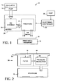
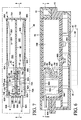
- Fig. 1 is a block diagram illustrating an inkjet printer.
- Fig. 2 is a block diagram illustrating one exemplary embodiment of an ink pen.
- Fig. 3 is an elevation view of one exemplary embodiment of an ink pen.
- Fig. 4 is an exploded perspective view of the ink pen shown in Fig. 3 .
- Fig. 5 is a perspective view of the pen body in the ink pen of Figs. 3 and 4 .
- Fig. 6 is an elevation section view of the ink pen shown in Figs. 3 and 4 taken along the line 6-6 in Fig. 7 .
- Fig. 7 is a plan section view of the pen body of the ink pen shown in Figs. 3 and 4 taken along the line 7-7 in Fig. 6 .
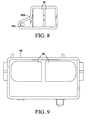
- Fig. 8 is an elevation view of one exemplary embodiment of a filter frame.
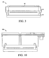
- Fig. 9 is an elevation view of a conventional filter frame.
- Fig. 10 is an elevation view of a conventional ink pen.
- Embodiments of the present invention were developed in an effort to reduce the size of a higher performance, "off axis" inkjet ink pen. Exemplary embodiments of the invention will be described, therefore, with reference to an off axis ink pen and an inkjet printer. Embodiments of the invention, however, are not limited to the exemplary ink pen or printer shown and described below. Other forms, details, and embodiments may be made and implemented. Hence, the following description should not be construed to limit the scope of the invention, which is defined in the claims that follow the description.
- inkjet printer 10 includes a printhead 12, an ink supply 14, a pump 16, a print media transport mechanism 18 and an electronic printer controller 20.
- Printhead 12 in Fig. 1 represents generally one or more printheads and the associated mechanical and electrical components for ejecting drops of ink on to a sheet or strip of print media 22.
- a typical thermal inkjet printhead includes a nozzle plate arrayed with ink ejection nozzles and firing resistors formed on an integrated circuit chip positioned behind the ink ejection nozzles. The ink ejection nozzles are usually arrayed in columns along the nozzle plate. Each printhead is operatively connected to printer controller 20 and ink supply 14.
- printer controller 20 selectively energizes the firing resistors and, when a firing resistor is energized, a vapor bubble forms in the ink vaporization chamber, ejecting a drop of ink through a nozzle on to the print media 22.
- piezoelectric elements instead of firing resistors are used to eject ink from a nozzle. Piezoelectric elements located close to the nozzles are caused to deform very rapidly to eject ink through the nozzles.
- An ink chamber 24 and printhead 12 are often housed together in an ink pen 26, as indicated by the dashed line in Fig. 1 .
- Ink flows to printhead 12 from ink supply 14 through ink chamber 24.
- Ink pens like ink pen 26, which allow the ink to be replaced as it is consumed from a remote, refillable, ink supply 14, are sometimes referred to as "off axis" pens.
- Ink chamber 24 represents generally one or more ink chambers 24 in pen 26 through which ink passes on its way to printhead 12. For example, as described below, the ink may pass through a filter chamber and a pressure regulating chamber before reaching the printhead.
- Printer 10 may include a series of stationary ink pens 26 that span the width of print media 22.
- printer 10 may include one or more ink pens 26 that are scanned back and forth across the width of media 22 on a moveable carriage.
- Media transport 18 advances print media 22 lengthwise past printhead 12.
- media transport 18 may advance media 22 continuously past printhead 12.
- media transport 18 may advance media 22 incrementally past pen 26, stopping as each swath is printed and then advancing media 22 for printing the next swath.
- Controller 20 receives print data from a computer or other host device 28 and processes that data into printer control information and image data. Controller 20 controls the movement of carriage, if any, and media transport 18. As noted above, controller 20 is electrically connected to printhead 12 to energize the firing resistors to eject ink drops on to media 22. By coordinating the relative position of pen(s) 26 and media 22 with the ejection of ink drops, controller 20 produces the desired image on media 22 according to the print data received from host device 28.
- Fig. 2 is a block diagram illustrating one exemplary embodiment of an ink pen 26.
- ink is pumped into a filter chamber 30 in pen 26 from a separate ink supply (not shown) through an inlet 32.
- Ink passes through a filter 34 in filter chamber 30 before flowing into a regulator chamber 36.
- Ink chamber 24 from Fig. 1 may include a filter chamber 30 and a regulator chamber 36 from the embodiment of ink pen 26 shown in Fig. 2 .
- Ink flows from regulator chamber 36 to printhead 12 where it may be ejected on to print media as described above.
- a pressure regulator 38 in chamber 36 maintains the pressure in chamber 36 within a desired range of negative pressures.
- Pressure regulator 38 represents generally any suitable pressure regulator.
- the spring bag type pressure regulator used in the ink pens for the Edgeline Technology (registered trade mark) printing products marketed by Hewlett-Packard Company may be adapted for use as pressure regulator 38 in pen 26.
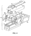
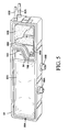
- Figs. 3-7 illustrate one exemplary embodiment of an ink pen 40 that may be used as a pen 26 shown in the block diagrams of Figs. 1 and 2 .
- Fig. 3 is an elevation view of the exterior of pen 40.
- Fig. 4 is an exploded perspective view of ink pen 40.
- Fig. 5 is a perspective view showing the internal design of the pen body and
- Figs. 6 and 7 are elevation and plan section views, respectively, of ink pen 40.
- pen 40 includes a lower exterior housing 42, an upper exterior housing 44, and a cover or cap 46.
- the printheads (not shown) are housed in lower housing 42 so that printhead nozzle plates 48 ( Fig.
- pen 40 is exposed along the bottom of pen 40 for ejecting ink drops 50 ( Fig. 6 ) on to paper or other print media 52 ( Fig. 6 ).
- the body 54 of pen 40 is housed within upper and lower housings 42 and 44, as best seen in the section view of Fig. 6 .
- ink pen 40 is configured to receive and eject two different inks.
- Pen body 54 is divided lengthwise into units 56A and 56B by a central barrier 58.
- the exploded perspective of pen 40 in Fig. 4 is viewed looking into the inlet side of pen body unit 56A (which is the outlet side of unit 56B) while the detail perspective of pen body 54 in Fig. 5 is viewed looking into the inlet side of pen body unit 56B (which is the outlet side of unit 56A).
- Ink flows through each pen body unit 56A and 56B to a separate printhead.
- ink inlet ports 60A and 60B are connected to an off axis ink supply and pumping system (not shown in Figs. 3-7 ), such as an ink supply 14 and pump 16 illustrated in the block diagram of Fig. 1 .
- Ink is pumped through inlet ports 60A and 60B into corresponding filter chambers 62A and 62B, which are enclosed by a cover plate 63A and 63B ( Fig. 4 ).
- a filter 64A, 64B is supported on a filter frame 66A, 66B in each filter chamber 62A, 62B.
- Each filter frame 66A, 66B is positioned in chamber 62A, 62B with an inboard face 67A, 67B facing central barrier 58 and an outboard face 68A, 68B.
- Each filter 64A, 64B is supported on both the inboard and outboard faces 67A/68A, 67A/68B of filter frame 66A, 66B.
- each filter chamber 62A, 62B is divided into two sub-chambers by filter 64A, 64B -- an exterior/upstream sub-chamber 70A, 70B and an interior/downstream sub-chamber 72A, 72B.
- Each ink inlet port 60A, 60B opens into the exterior sub-chamber 70A, 70B of filter chamber 62A, 62B.
- a passage 74A, 74B through barrier 58 to pressure regulator chambers 76A, 76B is located at one corner of each filter chamber 62A, 62B.
- An opening 78A, 78B in the corner of each filter frame 66A, 66B exposes each passage 74A, 74B to interior filter sub-chambers 72A, 72B.
- An interior barrier 82 separates the A unit filter chamber 62A from the B unit regulator chamber 76B.
- An interior barrier 84 separates the B unit filter chamber 62B from the A unit regulator chamber 76A.
- a pressure regulator 86A, 86B in each regulator chamber 76A, 76B controls the flow of ink from filter chamber 62A, 62B into chamber 76A, 76B through passage 74A, 74B, and out of chamber 76A, 76B through outlets 88A, 88B to the corresponding printhead.
- Each pressure regulator 86A, 86B includes, or is operatively coupled to, a flow control valve 89 ( Figs. 6 and 7 ) that opens and closes each passage 74A, 74B in response to pressure changes in regulator chamber 76A, 76B.
- pressure regulator 86A, 86B closes flow valve 89 (or allows valve 89 to close if valve 89 is biased toward the closed position) to stop the flow of ink into chamber 76A, 76B.
- the pressure regulators and flow valves mentioned above are well known to those skilled in the art of inkjet printing and, therefore, are not shown or described in detail.
- each pressure regulator 86A, 86B is depicted generally as including an expandable/collapsible bag 90A, 90B and an expanded rigid cover 92A, 92B, any suitable pressure regulator may be used.
- the spring bag type pressure regulator used in the ink pens for HP's Edgeline Technology printers may be adapted for use as pressure regulators 86A and 86B in pen 40.
- an off axis ink pen can be substantially reduced by locating a filter chamber upstream from the pressure regulator chamber and moving the ink filter upstream from the pressure regulator, as shown in Figs. 2 and 3-7 .
- the pressure available to move ink through the filter is limited to the pressure generated by the pumping action of the ink drop generator in the printhead, typically only 1-2 inches of water. This lower pressure requires a larger filter to allow the desired flow of ink to the printhead.
- the ink supply inlet pressure typically 1-10 psi (28-277 inches of water)
- the filter chamber is a higher pressure chamber compared to the lower pressure regulator chamber.
- the much higher filter chamber pressure permits a much smaller filter to allow the desired flow to the printhead.
- filter frame 66B is shown in Fig. 8 and a corresponding conventional filter frame, designated part number 94, from an Edgeline Technology ink pen.
- the size of each filter frame 66B and 94 is proportionate. Not only is the filter/flow area 96 in filter frame 66B much smaller than the filter/flow area 98 in filter frame 94, but the overall size of filter frame 66B is but a small fraction of the overall size of the conventional filter frame 94.
- a conventional Edgeline Technology ink pen 100 shown in Fig. 10 utilizing filter frames 94 from Fig. 9 , is nearly twice the height of, and slightly longer than, an exemplary new ink pen 40 shown in Fig. 3 utilizing the exemplary new filter frames 66A and 66B and the exemplary new flow configuration described above.
- ink flow rate to filter area ratio will vary depending on the ink volume life of the pen, the pressure available to deliver ink to the pen, the size of the delivery tubes, the density of the filter media, and the cleanliness and viscosity of the ink, it is expected that an ink flow rate to filter area ratio of at least 15 may be achieved in many of the larger, higher performance inkjet pens like those used in the Hewlett-Packard Company Edgeline Technology printers (registered trade mark).
Landscapes
- Ink Jet (AREA)
- Particle Formation And Scattering Control In Inkjet Printers (AREA)
Claims (8)
- Ein Tintenstift für einen Tintenstrahldrucker, umfassend:einen Einlass (32, 60A oder 60B), der mit einer Tintenzuführung (14) des Tintenstrahldruckers (10) verbindbar ist;einen Auslass (88A und 88B), der mit einem Druckkopf (12) des Tintenstrahldruckers (10) verbindbar ist;einen Tintenstromweg (80) durch den Tintenstift, der sich von dem Einlass (32, 60A oder 60B) zu dem Auslass (88A und 88B) erstreckt;eine Tintenfilterkammer (30, 62A oder 62B), umfassend einen Filter (34, 64A oder 64B), wobei der Einlass (32, 60A oder 60B) mit der Tintenfilterkammer (30, 62A oder 62B) vor dem Filter (34, 64A oder 64B) entlang des Tintenstromweges (80) verbunden ist;eine Druckreglerkammer (36, 76A oder 76B) nach der Tintenfilterkammer (30, 62A oder 62B) entlang eines Tintenstromweges durch den Stift;einen Druckregler (38, 86A oder 86B) in der Druckreglerkammer (36, 76A oder 76B);einen Tintenstromdurchlass (74A oder 74B) von der Tintenfilterkammer (30, 62A oder 62B) zu der Druckreglerkammer (36, 76A oder 76B) nach dem Filter (34, 64A oder 64B) entlang des Tintenstromweges, so dass von dem Einlass (32, 60A oder 60B) zu dem Tintenstromdurchlass (74A oder 74B) strömende Tinte durch den Filter (34, 64A oder 64B) gelangt; undein Stromsteuerventil (89), das operativ ist, den Tintenstromdurchlass (74A oder 74B) als Antwort auf Druckänderungen in der Druckreglerkammer (36, 76A oder 76B) zu öffnen und zu schließen.
- Der Tintenstift nach Anspruch 1, der ferner einen Druckkopf (12) umfasst, der operativ mit der Druckreglerkammer (36, 76A oder 76B) verbunden ist, so dass Tinte von der Druckreglerkammer (36, 76A oder 76B) zu dem Druckkopf (12) strömen kann.
- Der Tintenstift nach Anspruch 1 oder 2, wobei
der Filter (34, 64A oder 64B) in der Tintenfilterkammer (30, 62A oder 62B) die Tintenfilterkammer (30, 62A oder 62B) in eine vorgeschaltete Teilkammer (70A oder 70B) und eine nachgeschaltete Teilkammer (72A oder 72B) aufteilt;
Tinte in die vorgeschaltete Teilkammer (70A oder 70B) der Tintenfilterkammer (30, 62A oder 62B) durch den Einlass (32, 60A oder 60B) strömen kann; und
der Tintenstromdurchlass (74A oder 74B) die nachgeschaltete Teilkammer (72A oder 72B) der Tintenfilterkammer (30, 62A oder 62B) und die Druckreglerkammer (36, 76A oder 76B) verbindet. - Der Tintenstift nach Anspruch 1 zum getrennten Ausstoßen von zwei Tinten, wobei
die Tintenfilterkammer (62A) an einer ersten Seite einer Barriere (58) positioniert ist, die für Tinte undurchlässig ist;
eine weitere Tintenfilterkammer (62B) an einer weiteren Seite der Barriere (58) gegenüber der ersten Seite der Barriere (58) positioniert ist;
ein weiterer Filter (64B) in der weiteren Tintenfilterkammer (62B) vorgesehen ist;
die Druckreglerkammer (76A) an der weiteren Seite der Barriere (58) positioniert ist;
eine weitere Druckreglerkammer (76B) an der ersten Seite der Barriere (58) positioniert ist;
ein weiterer Druckregler (86B) in der weiteren Druckreglerkammer (76B) vorgesehen ist;
ein weiterer Tinteneinlass (60B) vorgesehen ist, durch den Tinte in die weitere Tintenfilterkammer (62B) vor dem weiteren Filter (64B) gelangen kann;
sich der Tintenstromdurchlass (74A), der die Tintenfilterkammer (62A) mit der Druckreglerkammer (76A) verbindet, durch die Barriere (58) erstreckt, wobei der Tintenstromdurchlass (74A) nach dem Filter (64A) positioniert ist;
sich ein weiterer Tintenstromdurchlass (74B), der die weitere Tintenfilterkammer (62B) mit der weiteren Druckreglerkammer (76B) verbindet, durch die Barriere (58) erstreckt, wobei der weitere Tintenstromdurchlass (74B) nach dem weiteren Filter (64B) positioniert ist;
das Stromsteuerventil (89) operativ ist, den Tintenstromdurchlass (74A) als Antwort auf Druckänderungen in der Druckreglerkammer (76A) zu öffnen und zu schließen;
ein weiteres Stromsteuerventil (89) vorgesehen ist, das operativ ist, den weiteren Tintenstromdurchlass (74B) als Antwort auf Druckänderungen in der weiteren Druckreglerkammer (76B) zu öffnen und zu schließen;
ein erster Druckkopf (12) vorgesehen ist, der sich nach der Druckreglerkammer (76A) befindet und operativ damit verbunden ist; und
ein zweiter Druckkopf (12) vorgesehen ist, der sich nach der weiteren Druckreglerkammer (76B) befindet und operativ damit verbunden ist. - Der Tintenstift nach Anspruch 4, wobei:die Tintenfilterkammer (62A) und die weitere Druckreglerkammer (76B) der Länge nach benachbart zueinander, aber fluidtechnisch isoliert voneinander entlang der ersten Seite der Barriere (58) positioniert sind, und die weitere Tintenfilterkammer (62B) und die Druckreglerkammer (76A) der Länge nach benachbart zueinander, aber fluidtechnisch isoliert voneinander entlang der weiteren Seite der Barriere (58) positioniert sind; unddie Tintenfilterkammer (62A) und die weitere Tintenfilterkammer (62B) seitlich benachbart zueinander über die Barriere (58) positioniert sind, und die Druckreglerkammer (76A) und die weitere Druckreglerkammer (76B) seitlich benachbart zueinander über die Barriere (58) positioniert sind.
- Ein Verfahren, das in einem Tintenabgabesystem für einen Tintenstrahl-Tintenstift nach einem der Ansprüche 1 bis 5 implementiert ist, wobei das Verfahren folgendes umfasst:Pumpen von Tinte in die Tintenkammer (30, 62A oder 62B) bei einem ersten Druck;Filtern von Tinte in der Tintenkammer (30, 62A oder 62B);selektives Gestatten, dass gefilterte Tinte von der Tintenkammer (30, 62A oder 62B) in die Druckreglerkammer (36, 76A oder 76B) strömt; undPumpen von Tinte aus der Druckreglerkammer (36, 76A oder 76B) zu einem Druckkopf (12) bei einem zweiten Druck, der geringer als der erste Druck ist.
- Das Verfahren nach Anspruch 6, wobei der erste Druck im Bereich von 1-10 psi liegt und der zweite Druck im Bereich von 1-2 Zoll Wasser liegt.
- Das Verfahren nach Anspruch 6, wobei der erste Druck im Bereich von 1-10 psi liegt und das Filtern von Tinte in der ersten Kammer (30, 62A oder 62B) das Filtern von Tinte bei einer in cm3/Minute gemessenen Strömungsrate umfasst, die mindestens 15-mal größer als eine in cm2 gemessene Fläche ist, durch die die Tinte gefiltert wird.
Applications Claiming Priority (2)
| Application Number | Priority Date | Filing Date | Title |
|---|---|---|---|
| US11/739,293 US7922312B2 (en) | 2007-04-24 | 2007-04-24 | Compact ink delivery in an ink pen |
| PCT/US2008/061161 WO2008134317A1 (en) | 2007-04-24 | 2008-04-22 | Compact ink delivery in an ink pen |
Publications (3)
| Publication Number | Publication Date |
|---|---|
| EP2139693A1 EP2139693A1 (de) | 2010-01-06 |
| EP2139693A4 EP2139693A4 (de) | 2010-06-02 |
| EP2139693B1 true EP2139693B1 (de) | 2012-05-23 |
Family
ID=39886439
Family Applications (1)
| Application Number | Title | Priority Date | Filing Date |
|---|---|---|---|
| EP08746557A Not-in-force EP2139693B1 (de) | 2007-04-24 | 2008-04-22 | Kompakte tintenausgabe in einem tintenstift |
Country Status (6)
| Country | Link |
|---|---|
| US (1) | US7922312B2 (de) |
| EP (1) | EP2139693B1 (de) |
| CN (1) | CN101668637B (de) |
| BR (1) | BRPI0809719B1 (de) |
| TW (1) | TW200932556A (de) |
| WO (1) | WO2008134317A1 (de) |
Families Citing this family (16)
| Publication number | Priority date | Publication date | Assignee | Title |
|---|---|---|---|---|
| EP2325012A4 (de) * | 2009-01-09 | 2012-06-06 | Mimaki Eng Kk | Tintenzufuhrschaltkreis |
| EP2661373B1 (de) * | 2011-01-07 | 2016-08-31 | Hewlett-Packard Development Company, L.P. | Flüssigkeitsbehälter mit mehreren kammern |
| BR112013017078B1 (pt) | 2011-01-07 | 2021-11-16 | Hewlett-Packard Development Company, Lp | Contêiner de fluido usável com um mecanismo de formação de imagem |
| CN103282705B (zh) | 2011-01-07 | 2014-12-24 | 惠普发展公司,有限责任合伙企业 | 一体式多功能阀装置 |
| US8469501B2 (en) * | 2011-04-28 | 2013-06-25 | Eastman Kodak Company | Air extraction method for inkjet printhead |
| US9261209B2 (en) * | 2012-04-18 | 2016-02-16 | Hewlett-Packard Development Company, L.P. | Fluid coupling |
| US9162468B2 (en) | 2012-04-30 | 2015-10-20 | Hewlett-Packard Development Company, L.P. | Liquid supply |
| US9180673B2 (en) | 2012-04-30 | 2015-11-10 | Hewlett-Packard Development Company, L.P. | Liquid supply |
| ITVI20120276A1 (it) | 2012-10-19 | 2014-04-20 | New System Srl | Dispositivo di compensazione per una testa di stampa e gruppo di stampa comprendente tale dispositivo di compensazione |
| JP6364726B2 (ja) * | 2013-09-17 | 2018-08-01 | セイコーエプソン株式会社 | 液体収容容器 |
| US9914308B2 (en) | 2016-01-08 | 2018-03-13 | Canon Kabushiki Kaisha | Liquid ejection apparatus and liquid ejection head |
| US9925791B2 (en) | 2016-01-08 | 2018-03-27 | Canon Kabushiki Kaisha | Liquid ejection apparatus and liquid ejection head |
| US10046570B2 (en) | 2016-01-13 | 2018-08-14 | Océ Holding B.V. | Filter device for filtering ink and ink supply system for printing apparatus |
| EP3670195B1 (de) * | 2017-02-17 | 2024-04-10 | Canon Kabushiki Kaisha | Tintenstrahldruckvorrichtung |
| JP6949589B2 (ja) * | 2017-07-05 | 2021-10-13 | キヤノン株式会社 | 液体吐出ヘッド |
| WO2021242255A1 (en) * | 2020-05-29 | 2021-12-02 | Hewlett-Packard Development Company, L.P. | Printing fluid circulation |
Family Cites Families (14)
| Publication number | Priority date | Publication date | Assignee | Title |
|---|---|---|---|---|
| US3786517A (en) * | 1972-09-05 | 1974-01-15 | Ibm | Ink jet printer with ink system filter means |
| US4403227A (en) * | 1981-10-08 | 1983-09-06 | International Business Machines Corporation | Method and apparatus for minimizing evaporation in an ink recirculation system |
| JPH0717050A (ja) * | 1993-07-02 | 1995-01-20 | Brother Ind Ltd | インクジェットプリンタにおけるフィルタ装置 |
| JP3087535B2 (ja) | 1993-09-29 | 2000-09-11 | 日本電気株式会社 | インクジェットカートリッジ |
| US5777647A (en) * | 1994-10-31 | 1998-07-07 | Hewlett-Packard Company | Side-loaded pressure regulated free-ink ink-jet pen |
| US6234622B1 (en) * | 1997-04-30 | 2001-05-22 | Hewlett-Packard Company | Ink delivery system that utilizes a separate insertable filter carrier |
| CA2327067A1 (en) | 1999-12-06 | 2001-06-06 | Canon Kabushiki Kaisha | Surface reformed fiber body, liquid container using fiber absorber, and method of producing fiber absorber for use in liquid ejection |
| US6557990B2 (en) * | 2001-04-26 | 2003-05-06 | Hewlett-Packard Development Company | Evacuated structures for removing accumulated air |
| ES2301584T3 (es) | 2001-05-17 | 2008-07-01 | Seiko Epson Corporation | Cartucho de tinta. |
| KR100433529B1 (ko) * | 2001-12-04 | 2004-05-31 | 삼성전자주식회사 | 압력조절모듈을 구비한 잉크 카트리지 |
| US7188942B2 (en) * | 2003-08-06 | 2007-03-13 | Hewlett-Packard Development Company, L.P. | Filter for printhead assembly |
| JP4455277B2 (ja) | 2004-10-28 | 2010-04-21 | 株式会社アルバック | 印刷方法、ヘッドモジュール及び印刷装置 |
| JP2006198845A (ja) | 2005-01-19 | 2006-08-03 | Seiko Epson Corp | 充填方法、及び液体吐出装置 |
| US7661803B2 (en) * | 2006-07-31 | 2010-02-16 | Silverbrook Research Pty Ltd | Inkjet printhead with controlled de-prime |
-
2007
- 2007-04-24 US US11/739,293 patent/US7922312B2/en not_active Expired - Fee Related
-
2008
- 2008-04-17 TW TW097113909A patent/TW200932556A/zh unknown
- 2008-04-22 EP EP08746557A patent/EP2139693B1/de not_active Not-in-force
- 2008-04-22 BR BRPI0809719A patent/BRPI0809719B1/pt not_active IP Right Cessation
- 2008-04-22 CN CN2008800132520A patent/CN101668637B/zh not_active Expired - Fee Related
- 2008-04-22 WO PCT/US2008/061161 patent/WO2008134317A1/en not_active Ceased
Also Published As
| Publication number | Publication date |
|---|---|
| US20080266370A1 (en) | 2008-10-30 |
| CN101668637A (zh) | 2010-03-10 |
| US7922312B2 (en) | 2011-04-12 |
| CN101668637B (zh) | 2011-04-06 |
| BRPI0809719A2 (pt) | 2014-09-30 |
| EP2139693A1 (de) | 2010-01-06 |
| TW200932556A (en) | 2009-08-01 |
| WO2008134317A1 (en) | 2008-11-06 |
| BRPI0809719B1 (pt) | 2018-12-04 |
| EP2139693A4 (de) | 2010-06-02 |
Similar Documents
| Publication | Publication Date | Title |
|---|---|---|
| EP2139693B1 (de) | Kompakte tintenausgabe in einem tintenstift | |
| EP2195172B1 (de) | Fliesssteuerung in einem tintenstift | |
| US5880748A (en) | Ink delivery system for an inkjet pen having an automatic pressure regulation system | |
| CN100404264C (zh) | 一种墨盒以及具有该墨盒的供墨系统 | |
| JP4036934B2 (ja) | インク配送システム | |
| JP5209431B2 (ja) | インクジェット記録装置 | |
| EP1203666B1 (de) | Druckbasierte Tintenfüllstandmessung unterstützt durch einen druckregulierenden Element in einem Tintensack | |
| JPH10128994A5 (de) | ||
| JP4532831B2 (ja) | インクジェット記録装置 | |
| EP1188568B1 (de) | Tintenstrahldrucker | |
| JP4931610B2 (ja) | 液体吐出装置、画像形成装置、液体吐出方法 | |
| US6702436B2 (en) | Fluid ejection cartridge including a compliant filter | |
| JP4617657B2 (ja) | ダンパー構造による圧力調整方法 | |
| JP2007090638A (ja) | 記録ヘッド、およびインクジェット記録装置 | |
| US8591013B2 (en) | Fluid interconnection | |
| JP3991993B2 (ja) | 液体噴射装置 | |
| US12168353B2 (en) | Unified bulk ink cartridge for thermal inkjet printer | |
| JPH06246925A (ja) | 液体貯蔵容器、これを用いたプリントヘッドユニットおよびこれを搭載するプリント装置 | |
| JP2007268767A (ja) | インクジェットプリンタ | |
| JP2008036833A (ja) | インク充填方法 |
Legal Events
| Date | Code | Title | Description |
|---|---|---|---|
| PUAI | Public reference made under article 153(3) epc to a published international application that has entered the european phase |
Free format text: ORIGINAL CODE: 0009012 |
|
| 17P | Request for examination filed |
Effective date: 20091007 |
|
| AK | Designated contracting states |
Kind code of ref document: A1 Designated state(s): AT BE BG CH CY CZ DE DK EE ES FI FR GB GR HR HU IE IS IT LI LT LU LV MC MT NL NO PL PT RO SE SI SK TR |
|
| A4 | Supplementary search report drawn up and despatched |
Effective date: 20100507 |
|
| DAX | Request for extension of the european patent (deleted) | ||
| GRAP | Despatch of communication of intention to grant a patent |
Free format text: ORIGINAL CODE: EPIDOSNIGR1 |
|
| GRAS | Grant fee paid |
Free format text: ORIGINAL CODE: EPIDOSNIGR3 |
|
| GRAA | (expected) grant |
Free format text: ORIGINAL CODE: 0009210 |
|
| AK | Designated contracting states |
Kind code of ref document: B1 Designated state(s): AT BE BG CH CY CZ DE DK EE ES FI FR GB GR HR HU IE IS IT LI LT LU LV MC MT NL NO PL PT RO SE SI SK TR |
|
| REG | Reference to a national code |
Ref country code: GB Ref legal event code: FG4D |
|
| REG | Reference to a national code |
Ref country code: CH Ref legal event code: EP |
|
| REG | Reference to a national code |
Ref country code: AT Ref legal event code: REF Ref document number: 558883 Country of ref document: AT Kind code of ref document: T Effective date: 20120615 |
|
| REG | Reference to a national code |
Ref country code: IE Ref legal event code: FG4D |
|
| REG | Reference to a national code |
Ref country code: NL Ref legal event code: T3 |
|
| REG | Reference to a national code |
Ref country code: DE Ref legal event code: R096 Ref document number: 602008015878 Country of ref document: DE Effective date: 20120719 |
|
| REG | Reference to a national code |
Ref country code: LT Ref legal event code: MG4D Effective date: 20120523 |
|
| PG25 | Lapsed in a contracting state [announced via postgrant information from national office to epo] |
Ref country code: NO Free format text: LAPSE BECAUSE OF FAILURE TO SUBMIT A TRANSLATION OF THE DESCRIPTION OR TO PAY THE FEE WITHIN THE PRESCRIBED TIME-LIMIT Effective date: 20120823 Ref country code: SE Free format text: LAPSE BECAUSE OF FAILURE TO SUBMIT A TRANSLATION OF THE DESCRIPTION OR TO PAY THE FEE WITHIN THE PRESCRIBED TIME-LIMIT Effective date: 20120523 Ref country code: FI Free format text: LAPSE BECAUSE OF FAILURE TO SUBMIT A TRANSLATION OF THE DESCRIPTION OR TO PAY THE FEE WITHIN THE PRESCRIBED TIME-LIMIT Effective date: 20120523 Ref country code: LT Free format text: LAPSE BECAUSE OF FAILURE TO SUBMIT A TRANSLATION OF THE DESCRIPTION OR TO PAY THE FEE WITHIN THE PRESCRIBED TIME-LIMIT Effective date: 20120523 Ref country code: CY Free format text: LAPSE BECAUSE OF FAILURE TO SUBMIT A TRANSLATION OF THE DESCRIPTION OR TO PAY THE FEE WITHIN THE PRESCRIBED TIME-LIMIT Effective date: 20120523 Ref country code: IS Free format text: LAPSE BECAUSE OF FAILURE TO SUBMIT A TRANSLATION OF THE DESCRIPTION OR TO PAY THE FEE WITHIN THE PRESCRIBED TIME-LIMIT Effective date: 20120923 |
|
| REG | Reference to a national code |
Ref country code: AT Ref legal event code: MK05 Ref document number: 558883 Country of ref document: AT Kind code of ref document: T Effective date: 20120523 |
|
| PG25 | Lapsed in a contracting state [announced via postgrant information from national office to epo] |
Ref country code: GR Free format text: LAPSE BECAUSE OF FAILURE TO SUBMIT A TRANSLATION OF THE DESCRIPTION OR TO PAY THE FEE WITHIN THE PRESCRIBED TIME-LIMIT Effective date: 20120824 Ref country code: LV Free format text: LAPSE BECAUSE OF FAILURE TO SUBMIT A TRANSLATION OF THE DESCRIPTION OR TO PAY THE FEE WITHIN THE PRESCRIBED TIME-LIMIT Effective date: 20120523 Ref country code: HR Free format text: LAPSE BECAUSE OF FAILURE TO SUBMIT A TRANSLATION OF THE DESCRIPTION OR TO PAY THE FEE WITHIN THE PRESCRIBED TIME-LIMIT Effective date: 20120523 Ref country code: PT Free format text: LAPSE BECAUSE OF FAILURE TO SUBMIT A TRANSLATION OF THE DESCRIPTION OR TO PAY THE FEE WITHIN THE PRESCRIBED TIME-LIMIT Effective date: 20120924 Ref country code: SI Free format text: LAPSE BECAUSE OF FAILURE TO SUBMIT A TRANSLATION OF THE DESCRIPTION OR TO PAY THE FEE WITHIN THE PRESCRIBED TIME-LIMIT Effective date: 20120523 |
|
| PG25 | Lapsed in a contracting state [announced via postgrant information from national office to epo] |
Ref country code: BE Free format text: LAPSE BECAUSE OF FAILURE TO SUBMIT A TRANSLATION OF THE DESCRIPTION OR TO PAY THE FEE WITHIN THE PRESCRIBED TIME-LIMIT Effective date: 20120523 |
|
| PG25 | Lapsed in a contracting state [announced via postgrant information from national office to epo] |
Ref country code: AT Free format text: LAPSE BECAUSE OF FAILURE TO SUBMIT A TRANSLATION OF THE DESCRIPTION OR TO PAY THE FEE WITHIN THE PRESCRIBED TIME-LIMIT Effective date: 20120523 Ref country code: DK Free format text: LAPSE BECAUSE OF FAILURE TO SUBMIT A TRANSLATION OF THE DESCRIPTION OR TO PAY THE FEE WITHIN THE PRESCRIBED TIME-LIMIT Effective date: 20120523 Ref country code: CZ Free format text: LAPSE BECAUSE OF FAILURE TO SUBMIT A TRANSLATION OF THE DESCRIPTION OR TO PAY THE FEE WITHIN THE PRESCRIBED TIME-LIMIT Effective date: 20120523 Ref country code: SK Free format text: LAPSE BECAUSE OF FAILURE TO SUBMIT A TRANSLATION OF THE DESCRIPTION OR TO PAY THE FEE WITHIN THE PRESCRIBED TIME-LIMIT Effective date: 20120523 Ref country code: RO Free format text: LAPSE BECAUSE OF FAILURE TO SUBMIT A TRANSLATION OF THE DESCRIPTION OR TO PAY THE FEE WITHIN THE PRESCRIBED TIME-LIMIT Effective date: 20120523 Ref country code: EE Free format text: LAPSE BECAUSE OF FAILURE TO SUBMIT A TRANSLATION OF THE DESCRIPTION OR TO PAY THE FEE WITHIN THE PRESCRIBED TIME-LIMIT Effective date: 20120523 |
|
| PG25 | Lapsed in a contracting state [announced via postgrant information from national office to epo] |
Ref country code: IT Free format text: LAPSE BECAUSE OF FAILURE TO SUBMIT A TRANSLATION OF THE DESCRIPTION OR TO PAY THE FEE WITHIN THE PRESCRIBED TIME-LIMIT Effective date: 20120523 Ref country code: PL Free format text: LAPSE BECAUSE OF FAILURE TO SUBMIT A TRANSLATION OF THE DESCRIPTION OR TO PAY THE FEE WITHIN THE PRESCRIBED TIME-LIMIT Effective date: 20120523 |
|
| PLBE | No opposition filed within time limit |
Free format text: ORIGINAL CODE: 0009261 |
|
| STAA | Information on the status of an ep patent application or granted ep patent |
Free format text: STATUS: NO OPPOSITION FILED WITHIN TIME LIMIT |
|
| PG25 | Lapsed in a contracting state [announced via postgrant information from national office to epo] |
Ref country code: ES Free format text: LAPSE BECAUSE OF FAILURE TO SUBMIT A TRANSLATION OF THE DESCRIPTION OR TO PAY THE FEE WITHIN THE PRESCRIBED TIME-LIMIT Effective date: 20120903 |
|
| 26N | No opposition filed |
Effective date: 20130226 |
|
| REG | Reference to a national code |
Ref country code: DE Ref legal event code: R097 Ref document number: 602008015878 Country of ref document: DE Effective date: 20130226 |
|
| PG25 | Lapsed in a contracting state [announced via postgrant information from national office to epo] |
Ref country code: BG Free format text: LAPSE BECAUSE OF FAILURE TO SUBMIT A TRANSLATION OF THE DESCRIPTION OR TO PAY THE FEE WITHIN THE PRESCRIBED TIME-LIMIT Effective date: 20120823 |
|
| PG25 | Lapsed in a contracting state [announced via postgrant information from national office to epo] |
Ref country code: MC Free format text: LAPSE BECAUSE OF FAILURE TO SUBMIT A TRANSLATION OF THE DESCRIPTION OR TO PAY THE FEE WITHIN THE PRESCRIBED TIME-LIMIT Effective date: 20120523 |
|
| REG | Reference to a national code |
Ref country code: CH Ref legal event code: PL |
|
| REG | Reference to a national code |
Ref country code: IE Ref legal event code: MM4A |
|
| PG25 | Lapsed in a contracting state [announced via postgrant information from national office to epo] |
Ref country code: CH Free format text: LAPSE BECAUSE OF NON-PAYMENT OF DUE FEES Effective date: 20130430 Ref country code: LI Free format text: LAPSE BECAUSE OF NON-PAYMENT OF DUE FEES Effective date: 20130430 |
|
| PG25 | Lapsed in a contracting state [announced via postgrant information from national office to epo] |
Ref country code: IE Free format text: LAPSE BECAUSE OF NON-PAYMENT OF DUE FEES Effective date: 20130422 |
|
| PG25 | Lapsed in a contracting state [announced via postgrant information from national office to epo] |
Ref country code: MT Free format text: LAPSE BECAUSE OF FAILURE TO SUBMIT A TRANSLATION OF THE DESCRIPTION OR TO PAY THE FEE WITHIN THE PRESCRIBED TIME-LIMIT Effective date: 20120523 |
|
| PG25 | Lapsed in a contracting state [announced via postgrant information from national office to epo] |
Ref country code: TR Free format text: LAPSE BECAUSE OF FAILURE TO SUBMIT A TRANSLATION OF THE DESCRIPTION OR TO PAY THE FEE WITHIN THE PRESCRIBED TIME-LIMIT Effective date: 20120523 |
|
| PG25 | Lapsed in a contracting state [announced via postgrant information from national office to epo] |
Ref country code: HU Free format text: LAPSE BECAUSE OF FAILURE TO SUBMIT A TRANSLATION OF THE DESCRIPTION OR TO PAY THE FEE WITHIN THE PRESCRIBED TIME-LIMIT; INVALID AB INITIO Effective date: 20080422 Ref country code: LU Free format text: LAPSE BECAUSE OF NON-PAYMENT OF DUE FEES Effective date: 20130422 |
|
| REG | Reference to a national code |
Ref country code: FR Ref legal event code: PLFP Year of fee payment: 9 |
|
| PGFP | Annual fee paid to national office [announced via postgrant information from national office to epo] |
Ref country code: NL Payment date: 20160321 Year of fee payment: 9 |
|
| REG | Reference to a national code |
Ref country code: FR Ref legal event code: PLFP Year of fee payment: 10 |
|
| REG | Reference to a national code |
Ref country code: FR Ref legal event code: PLFP Year of fee payment: 11 |
|
| REG | Reference to a national code |
Ref country code: NL Ref legal event code: MM Effective date: 20170501 |
|
| PG25 | Lapsed in a contracting state [announced via postgrant information from national office to epo] |
Ref country code: NL Free format text: LAPSE BECAUSE OF NON-PAYMENT OF DUE FEES Effective date: 20170501 |
|
| PGFP | Annual fee paid to national office [announced via postgrant information from national office to epo] |
Ref country code: GB Payment date: 20210324 Year of fee payment: 14 |
|
| PGFP | Annual fee paid to national office [announced via postgrant information from national office to epo] |
Ref country code: FR Payment date: 20210608 Year of fee payment: 15 |
|
| PGFP | Annual fee paid to national office [announced via postgrant information from national office to epo] |
Ref country code: DE Payment date: 20210528 Year of fee payment: 15 |
|
| GBPC | Gb: european patent ceased through non-payment of renewal fee |
Effective date: 20220422 |
|
| PG25 | Lapsed in a contracting state [announced via postgrant information from national office to epo] |
Ref country code: GB Free format text: LAPSE BECAUSE OF NON-PAYMENT OF DUE FEES Effective date: 20220422 |
|
| REG | Reference to a national code |
Ref country code: DE Ref legal event code: R119 Ref document number: 602008015878 Country of ref document: DE |
|
| PG25 | Lapsed in a contracting state [announced via postgrant information from national office to epo] |
Ref country code: FR Free format text: LAPSE BECAUSE OF NON-PAYMENT OF DUE FEES Effective date: 20230430 Ref country code: DE Free format text: LAPSE BECAUSE OF NON-PAYMENT OF DUE FEES Effective date: 20231103 |