EP2139684B1 - Methods for assembly disassembly and transformation of a printing group for a printing press and a corresponding transport device - Google Patents
Methods for assembly disassembly and transformation of a printing group for a printing press and a corresponding transport device Download PDFInfo
- Publication number
- EP2139684B1 EP2139684B1 EP08735087A EP08735087A EP2139684B1 EP 2139684 B1 EP2139684 B1 EP 2139684B1 EP 08735087 A EP08735087 A EP 08735087A EP 08735087 A EP08735087 A EP 08735087A EP 2139684 B1 EP2139684 B1 EP 2139684B1
- Authority
- EP
- European Patent Office
- Prior art keywords
- frame
- doctor blade
- transport device
- blade system
- carriage
- Prior art date
- Legal status (The legal status is an assumption and is not a legal conclusion. Google has not performed a legal analysis and makes no representation as to the accuracy of the status listed.)
- Active
Links
Images

Classifications
-
- B—PERFORMING OPERATIONS; TRANSPORTING
- B41—PRINTING; LINING MACHINES; TYPEWRITERS; STAMPS
- B41F—PRINTING MACHINES OR PRESSES
- B41F31/00—Inking arrangements or devices
- B41F31/30—Arrangements for tripping, lifting, adjusting, or removing inking rollers; Supports, bearings, or forks therefor
- B41F31/302—Devices for tripping inking devices as a whole
-
- B—PERFORMING OPERATIONS; TRANSPORTING
- B41—PRINTING; LINING MACHINES; TYPEWRITERS; STAMPS
- B41F—PRINTING MACHINES OR PRESSES
- B41F9/00—Rotary intaglio printing presses
- B41F9/06—Details
- B41F9/08—Wiping mechanisms
- B41F9/10—Doctors, scrapers, or like devices
-
- B—PERFORMING OPERATIONS; TRANSPORTING
- B41—PRINTING; LINING MACHINES; TYPEWRITERS; STAMPS
- B41F—PRINTING MACHINES OR PRESSES
- B41F9/00—Rotary intaglio printing presses
- B41F9/06—Details
- B41F9/18—Auxiliary devices for exchanging forme cylinders
Definitions
- the present invention relates to a method of mounting a printing unit for a printing machine.
- the invention also relates to a method of disassembling a printing unit for a printing machine.
- the invention also relates to a method of converting a printing unit for a printing machine.
- the invention relates to a transport device that can be used in a method for mounting, dismantling and / or transforming a printing unit, intended for a printing machine.
- the present invention also relates to a device for use in entering a printing unit for a printing machine.
- the printing group is more specifically used in a gravure printing machine.
- Photogravure also called rotogravure
- rotogravure is a rotary printing process that can be used for many substrates, including paper or cardboard, using engraved cylinders. Gravure printing is used especially for high-quality editions and large prints where graphics must play an important role in promoting a product, such as a carton pack. In one pass, this printing process can print up to twelve or more colors with solvent inks.
- a gravure printing machine a medium to be printed in the form of a continuous strip passes through a succession of gravure printing units. The printing units are assembled and arranged longitudinally one after the other from the input of the print medium upstream to its output downstream. Each printing group proceeds to print a pattern with a single specific color or a particular varnish, or else performs an embossing.
- the document US-3,625,145 discloses a removable printer carriage for use in gravure printing to facilitate handling and permutation of the engraved rolls.
- the carriage comprises a frame, means cooperating with the support means of the printing unit, an engraved impression cylinder rotating relative to the carriage.
- This carriage fits into a volume located inside a printing unit, which integrates support means to receive it.
- the impression cylinder is locked to a drive mechanism.
- such a trolley is only used specifically for engraved cylinders.
- the squeegee system remains permanently mounted on the carriage and can not be removed easily.
- a gravure printing unit provided with two squeegee systems arranged longitudinally and on two opposite sides, with respect to the cylinder, so as to permit, if necessary, a front printing or a back printing.
- a carriage is used to facilitate the introduction and extraction of the cylinder in the printing unit, in a longitudinal direction relative to the printing unit.
- One of the squeegee systems is connected to a structural part of the printing unit. The structural member slides vertically along slideways between a lower position, in which the doctor blade is in the use position, and an upper position in which the same doctor system is at a higher elevation than above the cylinder.
- the carriage comprises a movable frame bringing or removing the removable part or parts. Transfer means and means for fixing the removable part or parts inside the printing unit are also provided.
- the introduction of removable parts must imperatively be done longitudinally and in one direction. None is planned to position the squeegee system for back printing.
- the purpose of the carriage is only to facilitate the introduction and exit of the removable parts for cleaning and repair operations.
- the internal coupling elements for the removable parts remain permanently attached to the printing unit.
- a main problem that the present invention proposes to solve is to implement a method of assembly, disassembly and / or transformation of a printing unit.
- a second problem is to realize a method of mounting a printing unit, using a transport device.
- a third problem is to obtain a method of disassembly and transformation of a printing unit, with the aim of changing its destination, with a transport device.
- a fourth problem is to develop a transport device to be used by being inserted inside a frame in a printing unit.
- Still another problem is that of positioning a squeegee system on a transport device and transferring it from that same device to the printing unit.
- An object of the invention is to solve the technical problems mentioned for the documents of the state of the art.
- the invention also relates to a transport device, able to transport a squeegee system, to enter inside and to exit outside a frame of a printing unit belonging to a printing machine, comprising a frame and a carrier element, characterized in that it has a capacity to enter and exit transversely relative to the frame, and in that the carrier element has a capacity to be movable in a substantially longitudinal direction, to take two positions extremes in upstream and downstream directions, so as to allow a connection or a separation, and a transport of the doctor blade system.
- the longitudinal direction is defined as the horizontal direction of progression of the medium to be printed throughout the printing machine.
- the upstream direction is defined as the horizontal direction from which the blank print media enters the printer group or the printing machine.
- the downstream direction is defined as the horizontal direction towards which the graphically printed medium exits the printing unit or the printing machine.
- the transverse direction is defined as the horizontal direction perpendicular to the direction of progression of the medium to be printed.
- the device not only allows the entry, exit and transport of the doctor blade system, but also an inverted positioning of the doctor blade system in the printing unit.
- the downstream position allows front-side printing and the upstream position allows for back side printing.
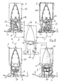
- a printing machine is composed of several printing units (1, 2, 3 and 4) which are successively mounted one after the other in order to constitute a printing machine.
- a support to be printed (6) returns upstream (Arrow I in Figure 1 ) in each of the printer groups (1, 2, 3 and 4), for example to be printed with a color, spring downstream (Arrow O).
- Each printing unit (1, 2, 3 and 4) comprises a printer carriage (7), itself having an engraved cylinder (8), an ink supply which brings the ink onto the engraved cylinder (8), a ink tray, which recovers the overflow of ink.
- Each printing unit (1, 2, 3 and 4) also has a frame (9), a dryer (11), which ensures the rapid evaporation of solvents or water, or the polymerization of UV inks, a pressure roller (12), which strongly presses the print medium (6) on the cylinder (8), and a pump which supplies ink from the reservoir to the ink applicator (not shown in FIG. Figure 1 ).
- the printing carriage (7) is inserted or inserted into an empty volume (13) formed in the center of the frame (9), being retracted transversely, that is to say perpendicularly to the direction of progression of the support (6).
- a squeegee system (14) removes excess ink on the cylinder (8) by means of a scraper blade, smoothing the peripheral surface of the cylinder (8) and leaving only ink that has penetrated into the cells .
- the squeegee system (14) is fixed to the frame (9).
- the squeegee system (14) protrudes into the volume (13) of the frame (9).
- the first printing unit (1) performs a single-sided printing and the second printing unit (2) performs a back printing of the print medium (6), which requires an inverted positioning of the squeegee system (14), downstream side or upstream side , relative to the direction of advance (I and O) of the medium to be printed (6), and a tracking mechanism different from the medium to be printed (6) inside the frame (9).
- a method of mounting a printing unit comprises several steps.
- a first step is to place the squeegee system (14) on a transport device or empty transport trolley (16), outside the frame (9).
- a second step is to enter or insert the transport carriage (16) with the squeegee system (14) in the frame (9) of the printing unit (1 and 2).
- the step of inserting the transport carriage (16) can be done transversely relative to the frame (9).
- the method may comprise an additional step, arranged after the step of inserting the transport carriage (16) with the doctor system (14). This step added may favorably center and lock this transport carriage (16) relative to the frame (9) of the printing unit (1 and 2).
- the mounting method may comprise an additional step arranged after the step of placing the doctor blade (14) on the empty transport carriage (16) before the step of inserting the transport carriage (16).
- this added step may consist in locking the doctor blade system (14) to this empty transport trolley (16).
- a third step is to secure the doctor blade system (14) to the frame (9).
- the joining of the squeegee system (14) is downstream side, to obtain a front printing unit (1).
- the joining of the squeegee system (14) is upstream side, to obtain a back printer group (2).
- a fourth step is to remove the empty transport carriage (16) out of the frame (9), outside the printing unit (1 or 2).
- a fifth step is to insert the printer carriage (7) in the frame (9). The method may comprise an additional step disposed after the step of inserting the printer carriage (7).
- This added step may favorably center and lock this printer carriage (7) relative to the frame (9) of the printing unit (1 and 2).
- the step of inserting the printer carriage (7) can be done transversely relative to the frame (9).
- a sixth step is to secure the printer carriage (7) to the frame (9).
- a disassembly process (Arrows D in Figure 1 ) and transforming a printer group (1 and 2) comprises several steps.
- a first step is to separate the printer carriage (7) from the frame (9).
- a second step is to leave the printer carriage (7) out of the frame (9), outside the printing unit (1 and 2).
- the step of removing this printer carriage (7) can be transversely to the frame (9).
- a third step is to insert an empty transport cart (16) into the frame (9).
- a fourth step is to separate the squeegee system (14) from the frame (9).
- a fifth step is to put the squeegee system (14) on the empty transport trolley (16).
- a sixth step is to remove the transport carriage (16) with the squeegee system (14) out of the frame (9) outside the printing unit (1 and 2).
- the step of taking out this transport carriage (16) can be done transversely with respect to the frame (9).
- the disassembly process may comprise an additional step, arranged after the step of placing the doctor blade (14) on the empty transport carriage (16), before the step of removing the transport carriage (16) with this squeegee system (14).
- this added step may consist in locking the doctor blade system (14) to this empty transport trolley (16).
- the method of converting the printing unit (1) may comprise two additional steps, arranged after the step of removing the transport carriage (16) with the doctor system (14).
- these added steps may consist in inserting this transport carriage (16) with a squeegee system (14) in an inverted position in the frame (9), and then in securing the system. doctor blade (14) in an inverted position at this frame (9) of the printing unit (2).
- the front printing unit (1) is transformed into a back printer group (2).
- the method may comprise an additional step, arranged after the step of inserting the transport carriage (16) with a squeegee system (14) in an inverted position. This added step may favorably center and lock this transport carriage (16) relative to the frame (9) of the printing unit (1 or 2).
- the process of converting the printing unit (1 and 2) may comprise two additional steps, arranged after the step of taking the transport carriage (16) out with the doctor blade system. (14). These added steps can consist in inserting (Arrow F in Figure 1 ) a flexographic printing carriage (17) in the frame (9) and then to secure the flexographic printing carriage (17) to this frame (9) of the printing unit (3).
- the step of inserting a flexographic printing carriage (17) can be done transversely with respect to the frame (9).
- the method may include an additional step arranged after the step of inserting a flexographic printing carriage (17). This added step may favorably center and lock this flexo printing carriage (17), relative to this frame (9) of the printing unit (3).
- the process of converting the printing unit (1 and 2) can comprise two additional steps, arranged after the step of taking out the transport carriage (16) with the squeegee system (14). .
- These added steps can consist of inserting (Arrow E in Figure 1 ) an embossing carriage (18) in the frame (9) and then to secure the embossing carriage (18) to the frame (9) of the printing unit (4).
- the step of inserting an embossing carriage (18) can be transverse to the frame (9).
- the method may comprise an additional step arranged after the step of inserting a carriage of embossing (18) in the frame (9).
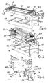
- the transport device or trolley (16) comprises a frame, similar to a table, in the form of a lower transverse base (19), a vertical upright (21), and a carrier element (22). ).
- the carrier element (22) is mounted on two transverse upper beams (23), starting from the vertical upright (21) and cantilevered relative to the base (19).
- the transport trolley (16) is easily moved by an operator with the aid of a small trolley with low wheels, devil type.
- the transport carriage (16) is dimensioned to penetrate and spring transversely out of the empty volume (13) of the frame (9) of the printing unit (1, 2, 3 and 4).
- the squeegee system (14) is placed on the carrier (22), so as to allow its transport.
- the carrier element (22) is movable in a substantially longitudinal direction, to take two extreme positions in upstream and downstream directions with respect to the direction of progression of the printing medium (6), so as to allow a joining or disconnection of the doctor blade system (14).
- the squeegee system (14) is secured to the printing unit (1) for the latter to perform a simplex printing.
- the squeegee system (14) is secured to the printing unit (2), so that the latter makes a back printing.
- the carrier member (22) comprises two longitudinal bars (24) connected by a transverse spacer (26).
- the squeegee system (14) rests on the two longitudinal bars (24).
- the two longitudinal bars (24) are slidably movable in two longitudinal rails (27), attached to the two upper beams (23).
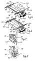
- the sliding is done in the upstream direction (SU arrows in Figure 5 ) and in the downstream direction (SD arrows in Figure 6 ).
- the sliding is achieved by meshing two longitudinal racks (28), fixed to the two longitudinal bars (24), with two longitudinal gears (29).
- the two gears (29) are interconnected by a rod (31) and driven by a steering wheel (32) and a handle (33).
- the transport trolley (16) may comprise centering means capable of cooperating with centering means, conjugate, corresponding and present in the frame of the printing unit.
- centering means comprise (see Figure 7 ) rear centering means (34), located at the distal transverse end of the transport carriage (16), that is to say opposite the flywheel (32) and being inaccessible to the operator when the transport carriage (16) is inserted into the printing unit (1 and 2).
- the rear centering means (34) are in the form of a cam follower (36) engaging a corresponding rear groove (37) forming part of the frame (9) of the printing unit (1 and 2).
- centering means comprise (see Figure 8 ) front centering means (38) located at the proximal transverse end of the transport carriage (16), i.e. flying side (32) and being accessible to the operator when the transport carriage (16) ) is inserted in the printer group (1 and 2).
- the front centering means (38) is in the form of an axis (39) engaging in a corresponding front groove (41) forming part of the frame (9) of the printing unit (1 and 2). It should be noted that the rear groove (37) and the front groove (41) of the frame (9) can also be used for the adjustment of the "skewing", which is a technique of adjustment by offsetting the engraved cylinder of the printing carriage (7). ).
- the transport trolley (16) may comprise locking means (42) capable of cooperating with locking means, conjugate, corresponding and present in the frame (9) of the printing unit (1 and 2). These locking means (42) comprise a bolt (43) located at the proximal transverse end of the transport carriage (16).
- the transport carriage (16) may comprise locking means (46) able to cooperate with locking means, conjugate, corresponding and present at the squeegee system (14).
- These means locking members (46) are part of the two longitudinal bars (24).
- the locking means comprise two studs provided with an abutment (47), each provided on the two longitudinal bars (24), and against which the respective slice of the longitudinal plates (48) of the scraper system (14) comes to rest .
- These locking means (47) also comprise two pins (49), respectively inserting both into a hole in the stud (47) and in the longitudinal plates (48) of the doctor system (14).
Landscapes
- Engineering & Computer Science (AREA)
- Mechanical Engineering (AREA)
- Rotary Presses (AREA)
- Screen Printers (AREA)
- Printing Methods (AREA)
- Inking, Control Or Cleaning Of Printing Machines (AREA)
Abstract
Description
La présente invention concerne un procédé de montage d'un groupe imprimeur pour une machine d'impression. L'invention concerne également un procédé de démontage d'un groupe imprimeur pour une machine d'impression. L'invention concerne également un procédé de transformation d'un groupe imprimeur pour une machine d'impression. L'invention concerne un dispositif de transport utilisable dans un procédé de montage, de démontage et/ou de transformation d'un groupe imprimeur, destiné à une machine d'impression. La présente invention se rapporte également à un dispositif destiné à être utilisé en étant entré dans un groupe imprimeur destiné à une machine d'impression. Le groupe imprimeur est plus spécifiquement utilisé dans une machine d'impression en héliogravure.The present invention relates to a method of mounting a printing unit for a printing machine. The invention also relates to a method of disassembling a printing unit for a printing machine. The invention also relates to a method of converting a printing unit for a printing machine. The invention relates to a transport device that can be used in a method for mounting, dismantling and / or transforming a printing unit, intended for a printing machine. The present invention also relates to a device for use in entering a printing unit for a printing machine. The printing group is more specifically used in a gravure printing machine.
L'héliogravure, également appelée hélio est un procédé d'impression rotatif utilisable pour de nombreux supports, dont le papier ou le carton, utilisant des cylindres gravés. L'impression en hélio est employée particulièrement pour les éditions de grande qualité et de grands tirages où le graphisme doit jouer un rôle important pour assurer la promotion d'un produit, tel qu'un emballage sous la forme d'une boîte en carton. Ce procédé d'impression permet en un seul passage d'imprimer jusqu'à douze couleurs, voire plus, avec des encres à solvants.
Ainsi, dans une machine d'impression en hélio, un support à imprimer sous la forme d'une bande continue traverse une succession de groupes imprimeurs hélio. Les groupes imprimeurs sont assemblés et disposés longitudinalement les uns à la suite des autres depuis l'entrée du support à imprimer en amont jusqu'à sa sortie en aval. Chaque groupe imprimeur procède à l'impression d'un motif avec une seule couleur spécifique ou un vernis particulier, ou bien encore effectue un gaufrage.
De plus en plus d'utilisateurs veulent posséder une machine d'impression présentant une grande souplesse d'utilisation. Ainsi, tout d'abord, ils souhaitent effectuer des changements extrêmement rapides de travail par modification des cylindres d'impression gravés, afin de faire face aux demandes de plus en plus ponctuelles d'impression en petites séries de leurs clients. Ensuite, le besoin s'est fait sentir en terme d'effets visuels supplémentaires devant être reproduits sur le support, tels que dorures et argentures, vernis mats, brillants ou structurés, recto, verso, gaufrages, et d'autres encore, nécessitant par là même de nouvelles techniques d'impression. Cependant, en raison de la longueur des machines d'impression et en raison des coûts très élevés, ils peuvent rarement rajouter des groupes d'impression supplémentaires en milieu de machine d'impression.Photogravure, also called rotogravure, is a rotary printing process that can be used for many substrates, including paper or cardboard, using engraved cylinders. Gravure printing is used especially for high-quality editions and large prints where graphics must play an important role in promoting a product, such as a carton pack. In one pass, this printing process can print up to twelve or more colors with solvent inks.
Thus, in a gravure printing machine, a medium to be printed in the form of a continuous strip passes through a succession of gravure printing units. The printing units are assembled and arranged longitudinally one after the other from the input of the print medium upstream to its output downstream. Each printing group proceeds to print a pattern with a single specific color or a particular varnish, or else performs an embossing.
More and more users want to have a printing machine with great flexibility. So, first of all, they want to make extremely fast changes of work by modifying engraved print cylinders, in order to cope with the demands of more and more punctual printing in small series of their customers. Then, the need was felt in terms of additional visual effects to be reproduced on the support, such as gilding and silvering, matte, glossy or structured varnishes, front, back, embossing, and others, requiring by there even new printing techniques. However, because of the length of the printing machines and because of the very high costs, they can rarely add additional printing units in the middle of the printing machine.
Pour faciliter cette adaptabilité des groupes imprimeurs, le document
Cependant, un tel chariot n'est utilisé spécifiquement que pour les cylindres gravés. De plus, le système de racle reste monté à demeure sur le chariot et ne peut être enlevé de manière aisée.
On connaît d'après le document
Cependant, un tel groupe imprimeur exige la présence à demeure de deux systèmes de racle, l'un des deux restant inutilisé lorsque l'autre fonctionne. Un système de racle surnuméraire rend le groupe imprimeur coûteux. De plus, rien n'est prévu pour enlever le ou les systèmes de racle, pour des interventions sur le groupe imprimeur ou pour d'autres modifications de ce même groupe imprimeur.
Le document
Cependant, un tel chariot reste spécifiquement dédié à ce groupe imprimeur, dont l'introduction des parties amovibles doit impérativement se faire longitudinalement et dans un seul sens. Rien n'est prévu pour positionner le système de racle pour une impression verso. De plus, le but du chariot n'est que de faciliter l'introduction et la sortie des parties amovibles pour des interventions de nettoyage et de réparation. Les éléments d'accouplement internes pour les parties amovibles restent fixés à demeure au groupe imprimeur.To facilitate this adaptability of printing groups, the document
However, such a trolley is only used specifically for engraved cylinders. In addition, the squeegee system remains permanently mounted on the carriage and can not be removed easily.
We know from the document
However, such a printing unit requires the permanent presence of two squeegee systems, one of the two remaining unused when the other operates. A supernumerary squeegee system makes the printer group expensive. In addition, nothing is planned for remove the squeegee system (s), for interventions on the printer group or for other modifications of the same printer group.
The document
However, such a carriage remains specifically dedicated to this printing group, the introduction of removable parts must imperatively be done longitudinally and in one direction. Nothing is planned to position the squeegee system for back printing. In addition, the purpose of the carriage is only to facilitate the introduction and exit of the removable parts for cleaning and repair operations. The internal coupling elements for the removable parts remain permanently attached to the printing unit.
Un problème principal que se propose de résoudre la présente invention consiste à mettre en oeuvre un procédé de montage, de démontage et/ou de transformation d'un groupe imprimeur. Un deuxième problème est de réaliser un procédé de montage d'un groupe imprimeur, à l'aide d'un dispositif de transport. Un troisième problème est d'obtenir un procédé de démontage et de transformation d'un groupe imprimeur, dans le but d'en changer sa destination, avec un dispositif de transport. Un quatrième problème est de mettre au point un dispositif de transport destiné à être utilisé en étant inséré à l'intérieur d'un bâti dans un groupe imprimeur. Un autre problème encore est celui de positionner un système de racle sur un dispositif de transport et de le transférer à partir de ce même dispositif vers le groupe imprimeur. Un but de l'invention est de résoudre les problèmes techniques mentionnés pour les documents de l'état de la technique.A main problem that the present invention proposes to solve is to implement a method of assembly, disassembly and / or transformation of a printing unit. A second problem is to realize a method of mounting a printing unit, using a transport device. A third problem is to obtain a method of disassembly and transformation of a printing unit, with the aim of changing its destination, with a transport device. A fourth problem is to develop a transport device to be used by being inserted inside a frame in a printing unit. Still another problem is that of positioning a squeegee system on a transport device and transferring it from that same device to the printing unit. An object of the invention is to solve the technical problems mentioned for the documents of the state of the art.
Conformément à un aspect, la présente invention vise un procédé de montage d'un groupe imprimeur appartenant à une machine d'impression, le groupe imprimeur comprenant un bâti, un chariot imprimeur, apte à être entré à l'intérieur et à être solidarisé au bâti, et un système de racle, indépendant du chariot imprimeur et apte à être solidarisé à ce bâti.
Le procédé de montage est caractérisé en ce qu'il comprend les étapes consistant à:
- poser le système de racle sur un dispositif de transport vide,
- entrer ce dispositif de transport avec ce système de racle à l'intérieur de ce bâti,
- solidariser ce système de racle à ce bâti,
- sortir ce dispositif de transport vide à l'extérieur de ce bâti,
- entrer ce chariot imprimeur à l'intérieur de ce bâti, et
- solidariser ce chariot imprimeur à ce bâti.
The mounting method is characterized in that it comprises the steps of:
- put the squeegee system on an empty transport device,
- enter this transport device with this squeegee system inside this frame,
- solidariser this squeegee system to this frame,
- take out this empty transport device on the outside of this frame,
- enter this printer cart inside this rack, and
- secure this printer cart to this frame.
Autrement dit, en prévoyant un dispositif de transport spécifique au système de racle, ce dernier peut être facilement déplacé, pour permettre à l'opérateur de monter le groupe imprimeur en fonction de ses besoins. Le dispositif de transport est défini comme étant un ensemble, pouvant être déplacé, pouvant supporter le poids du système de racle, et muni ou non de roues, de type chariot de transport ou d'autres encore. Le dispositif de transport est dimensionné de manière adéquate, pour son entrée à l'intérieur et sa sortie à l'extérieur du bâti du groupe imprimeur, en étant manoeuvrable par un opérateur.
Conformément à un autre aspect, la présente invention vise un procédé de démontage et/ou de transformation d'un groupe imprimeur appartenant à une machine d'impression, le groupe imprimeur comprenant un bâti, un chariot imprimeur, entré à l'intérieur et solidarisé au bâti, et un système de racle, indépendant du chariot imprimeur et solidarisé à ce bâti.
Le procédé de démontage et/ou de transformation est caractérisé en ce qu'il comprend les étapes consistant à :
- désolidariser ce chariot imprimeur de ce bâti,
- sortir ce chariot imprimeur à l'extérieur de ce bâti,
- entrer un dispositif de transport vide à l'intérieur de ce bâti,
- désolidariser le système de racle de ce bâti,
- poser ce système de racle sur le dispositif de transport vide, et
- sortir ce dispositif de transport avec ce système de racle à l'extérieur de ce bâti.
According to another aspect, the present invention aims at a method of disassembly and / or transformation of a printing unit belonging to a printing machine, the printing unit comprising a frame, a printer carriage, entered inside and joined together. to the frame, and a squeegee system, independent of the printer carriage and secured to this frame.
The disassembly and / or transformation method is characterized in that it comprises the steps of:
- to separate this printer carriage from this frame,
- take out this printer cart outside this frame,
- enter an empty transport device inside this frame,
- to separate the squeegee system from this frame,
- put this squeegee system on the empty transport device, and
- take out this transport device with this squeegee system outside this frame.
En d'autres termes, avec le système de racle amovible, l'accès de l'opérateur aux autres organes du groupe imprimeur est facilité. En enlevant, le système de racle, l'opérateur dégage de la place à l'intérieur du groupe imprimeur, ce qui permet de modifier plus aisément ce même groupe imprimeur. De plus, avec le dispositif de transport et le chariot imprimeur, toute modification du groupe imprimeur reste très facile à effectuer par l'opérateur.
L'invention concerne également un dispositif de transport, apte à transporter un système de racle, à entrer à l'intérieur et à sortir à l'extérieur d'un bâti d'un groupe imprimeur appartenant à une machine d'impression, comprenant un châssis et un élément porteur, caractérisé en ce qu'il présente une capacité à entrer et à sortir transversalement par rapport au bâti, et en ce que l'élément porteur présente une capacité à être mobile selon une direction sensiblement longitudinale, pour prendre deux positions extrêmes dans des sens amont et aval, de façon à permettre une solidarisation ou une désolidarisation, et un transport du système de racle.
Dans toute la description, la direction longitudinale est définie comme étant la direction horizontale de progression du support à imprimer tout au long de la machine d'impression. Le sens amont est défini comme étant le sens horizontal à partir duquel le support à imprimer vierge entre dans le groupe imprimeur ou dans la machine d'impression. Le sens aval est défini comme étant le sens horizontal vers lequel le support imprimé graphiquement sort du groupe imprimeur ou de la machine d'impression. La direction transversale est définie comme étant la direction horizontale perpendiculaire à la direction de progression du support à imprimer.
Autrement dit, le dispositif permet non seulement l'entrée, la sortie et le transport du système de racle, mais également un positionnement inversé du système de racle dans le groupe imprimeur. La position en aval autorise l'impression côté recto et la position en amont autorise l'impression côté verso.In other words, with the removable squeegee system, the access of the operator to the other organs of the printing unit is facilitated. By removing the squeegee system, the operator clears space inside the printing unit, which makes it easier to modify the same printing unit. In addition, with the transport device and the printer carriage, any modification of the printing unit remains very easy to carry out by the operator.
The invention also relates to a transport device, able to transport a squeegee system, to enter inside and to exit outside a frame of a printing unit belonging to a printing machine, comprising a frame and a carrier element, characterized in that it has a capacity to enter and exit transversely relative to the frame, and in that the carrier element has a capacity to be movable in a substantially longitudinal direction, to take two positions extremes in upstream and downstream directions, so as to allow a connection or a separation, and a transport of the doctor blade system.
Throughout the description, the longitudinal direction is defined as the horizontal direction of progression of the medium to be printed throughout the printing machine. The upstream direction is defined as the horizontal direction from which the blank print media enters the printer group or the printing machine. The downstream direction is defined as the horizontal direction towards which the graphically printed medium exits the printing unit or the printing machine. The transverse direction is defined as the horizontal direction perpendicular to the direction of progression of the medium to be printed.
In other words, the device not only allows the entry, exit and transport of the doctor blade system, but also an inverted positioning of the doctor blade system in the printing unit. The downstream position allows front-side printing and the upstream position allows for back side printing.
L'invention sera bien comprise et ses divers avantages et différentes caractéristiques ressortiront mieux lors de la description suivante, de l'exemple non limitatif de réalisation, en référence aux dessins schématiques annexés, dans lesquels :
- la
Figure 1 représente une vue synoptique des différents procédés selon l'invention ;
- laFigure 2 représente une vue en perspective d'un dispositif de transport selon l'invention ; - la
Figure 3 représente une vue en perspective d'un dispositif de transport avec un système de racle ; - la
Figure 4 représente une vue latérale partielle du dispositif de transport avec le système de racle ; - les
Figures 5 représentent respectivement des vues partielles en perspective montrant les deux positions extrêmes prises par un élément porteur du dispositif de transport ;et 6 - la
Figure 7 représente une vue en perspective partielle des moyens de centrage arrière du dispositif de transport par rapport au groupe imprimeur ; - la
Figure 8 représente une vue en perspective partielle des moyens de centrage avant du dispositif de transport par rapport au groupe imprimeur ; - la
Figure 9 représente une vue en perspective partielle des moyens de verrouillage du dispositif de transport au groupe imprimeur ; et - la
Figure 10 représente une vue en perspective partielle des moyens de verrouillage du système de racle au dispositif de transport.
- the
Figure 1 represents a synoptic view of the various methods according to the invention;
- theFigure 2 represents a perspective view of a transport device according to the invention; - the
Figure 3 is a perspective view of a transport device with a doctor blade system; - the
Figure 4 represents a partial side view of the transport device with the doctor blade system; - the
Figures 5 and 6 respectively represent partial perspective views showing the two extreme positions taken by a carrier element of the transport device; - the
Figure 7 represents a partial perspective view of the rear centering means of the transport device relative to the printing unit; - the
Figure 8 represents a partial perspective view of the front centering means of the transport device relative to the printing unit; - the
Figure 9 represents a partial perspective view of the locking means of the transport device to the printing unit; and - the
Figure 10 represents a partial perspective view of the locking means of the doctor blade system to the transport device.
Comme l'illustre la
Chaque groupe imprimeur (1, 2, 3 et 4) comprend un chariot imprimeur (7), présentant lui-même un cylindre gravé (8), une arrivée d'encre qui amène l'encre sur le cylindre gravé (8), un bac à encre, qui récupère le trop plein d'encre. Chaque groupe imprimeur (1, 2, 3 et 4) possède également un bâti (9), un sécheur (11), qui assure l'évaporation rapide des solvants ou de l'eau, ou bien la polymérisation des encres à UV, un rouleau presseur (12), qui appuie fortement le support à imprimer (6) sur le cylindre (8), et une pompe qui assure l'alimentation en encre du réservoir à l'applicateur d'encre (non représentée en
Un système de racle (14) élimine le surplus d'encre sur le cylindre (8) au moyen d'une lame de raclage, arasant la surface périphérique du cylindre (8) et ne laissant que l'encre qui a pénétré dans les alvéoles. Le système de racle (14) est fixé au bâti (9). Le système de racle (14) fait saillie dans le volume (13) du bâti (9).
Le premier groupe imprimeur (1) réalise une impression recto et le deuxième groupe imprimeur (2) réalise une impression verso du support à imprimer (6), ce qui demande un positionnement inversé du système de racle (14), côté aval ou côté amont, par rapport au sens d'avancement (I et O) du support à imprimer (6), et un mécanisme de cheminement différent du support à imprimer (6) à l'intérieur du bâti (9).
Comme le représente la
De manière très préférentielle, l'étape consistant à insérer le chariot de transport (16), peut se faire transversalement par rapport au bâti (9). Le procédé peut comprendre une étape supplémentaire, disposée après l'étape consistant à insérer le chariot de transport (16) avec le système de racle (14). Cette étape rajoutée peut favorablement consister à centrer et à verrouiller ce chariot de transport (16), par rapport à ce bâti (9) du groupe imprimeur (1 et 2).
Le procédé de montage peut comprendre une étape supplémentaire disposée après l'étape consistant à poser le système de racle (14) sur le chariot de transport vide (16), avant l'étape consistant à insérer ce chariot de transport (16). Avantageusement, cette étape rajoutée peut consister à verrouiller le système de racle (14) à ce chariot de transport vide (16).
Une troisième étape consiste à solidariser le système de racle (14) au bâti (9). Dans une première forme de mise en oeuvre de la troisième étape (Flèche R en
Le procédé peut comprendre une étape supplémentaire, disposée après l'étape consistant à insérer le chariot imprimeur (7). Cette étape rajoutée peut consister favorablement à centrer et à verrouiller ce chariot imprimeur (7), par rapport à ce bâti (9) du groupe imprimeur (1 et 2). De manière très préférentielle, l'étape consistant à insérer le chariot imprimeur (7), peut se faire transversalement par rapport au bâti (9). Une sixième étape consiste à solidariser le chariot imprimeur (7) au bâti (9).
Comme le représente la
Une troisième étape consiste à insérer un chariot de transport vide (16) dans le bâti (9). Une quatrième étape consiste à désolidariser le système de racle (14) du bâti (9). Une cinquième étape consiste à poser le système de racle (14) sur le chariot de transport vide (16). Une sixième étape consiste à sortir le chariot de transport (16) avec le système de racle (14) hors du bâti (9) à l'extérieur du groupe imprimeur (1 et 2). De manière très préférentielle, l'étape consistant à sortir ce chariot de transport (16), peut se faire transversalement par rapport au bâti (9).
Le procédé de démontage peut comprendre une étape supplémentaire, disposée après l'étape consistant à poser le système de racle (14) sur le chariot de transport vide (16), avant l'étape consistant à sortir ce chariot de transport (16) avec ce système de racle (14). Avantageusement, cette étape rajoutée peut consister à verrouiller le système de racle (14) à ce chariot de transport vide (16).As illustrated by
Each printing unit (1, 2, 3 and 4) comprises a printer carriage (7), itself having an engraved cylinder (8), an ink supply which brings the ink onto the engraved cylinder (8), a ink tray, which recovers the overflow of ink. Each printing unit (1, 2, 3 and 4) also has a frame (9), a dryer (11), which ensures the rapid evaporation of solvents or water, or the polymerization of UV inks, a pressure roller (12), which strongly presses the print medium (6) on the cylinder (8), and a pump which supplies ink from the reservoir to the ink applicator (not shown in FIG.
A squeegee system (14) removes excess ink on the cylinder (8) by means of a scraper blade, smoothing the peripheral surface of the cylinder (8) and leaving only ink that has penetrated into the cells . The squeegee system (14) is fixed to the frame (9). The squeegee system (14) protrudes into the volume (13) of the frame (9).
The first printing unit (1) performs a single-sided printing and the second printing unit (2) performs a back printing of the print medium (6), which requires an inverted positioning of the squeegee system (14), downstream side or upstream side , relative to the direction of advance (I and O) of the medium to be printed (6), and a tracking mechanism different from the medium to be printed (6) inside the frame (9).
As represented by
Very preferably, the step of inserting the transport carriage (16), can be done transversely relative to the frame (9). The method may comprise an additional step, arranged after the step of inserting the transport carriage (16) with the doctor system (14). This step added may favorably center and lock this transport carriage (16) relative to the frame (9) of the printing unit (1 and 2).
The mounting method may comprise an additional step arranged after the step of placing the doctor blade (14) on the empty transport carriage (16) before the step of inserting the transport carriage (16). Advantageously, this added step may consist in locking the doctor blade system (14) to this empty transport trolley (16).
A third step is to secure the doctor blade system (14) to the frame (9). In a first embodiment of the third step (Arrow R in
The method may comprise an additional step disposed after the step of inserting the printer carriage (7). This added step may favorably center and lock this printer carriage (7) relative to the frame (9) of the printing unit (1 and 2). Very preferably, the step of inserting the printer carriage (7), can be done transversely relative to the frame (9). A sixth step is to secure the printer carriage (7) to the frame (9).
As represented by
A third step is to insert an empty transport cart (16) into the frame (9). A fourth step is to separate the squeegee system (14) from the frame (9). A fifth step is to put the squeegee system (14) on the empty transport trolley (16). A sixth step is to remove the transport carriage (16) with the squeegee system (14) out of the frame (9) outside the printing unit (1 and 2). In a very preferential manner, the step of taking out this transport carriage (16) can be done transversely with respect to the frame (9).
The disassembly process may comprise an additional step, arranged after the step of placing the doctor blade (14) on the empty transport carriage (16), before the step of removing the transport carriage (16) with this squeegee system (14). Advantageously, this added step may consist in locking the doctor blade system (14) to this empty transport trolley (16).
Le procédé de transformation du groupe imprimeur (1) peut comprendre deux étapes supplémentaires, disposées après l'étape consistant à sortir le chariot de transport (16) avec le système de racle (14). Dans une première variante de mise en oeuvre de ce procédé, ces étapes rajoutées peuvent consister à insérer ce chariot de transport (16) avec un système de racle (14) en position inversée dans le bâti (9), et ensuite à solidariser le système de racle (14) en position inversée à ce bâti (9) du groupe imprimeur (2). Le groupe imprimeur recto (1) est transformé en groupe imprimeur verso (2). Le procédé peut comprendre une étape supplémentaire, disposée après l'étape consistant à insérer le chariot de transport (16) avec un système de racle (14) en position inversée. Cette étape rajoutée peut consister favorablement à centrer et à verrouiller ce chariot de transport (16), par rapport à ce bâti (9) du groupe imprimeur (1 ou 2).
Dans une deuxième variante de mise en oeuvre de ce procédé, le procédé de transformation du groupe imprimeur (1 et 2) peut comprendre deux étapes supplémentaires, disposées après l'étape consistant à sortir le chariot de transport (16) avec le système de racle (14). Ces étapes rajoutées peuvent consister à insérer (Flèche F en
De manière très préférentielle, l'étape consistant à insérer un chariot d'impression flexographie (17), peut se faire transversalement par rapport au bâti (9). Le procédé peut comprendre une étape supplémentaire, disposée après l'étape consistant à insérer un chariot d'impression flexographie (17). Cette étape rajoutée peut consister favorablement à centrer et à verrouiller ce chariot d'impression flexo (17), par rapport à ce bâti (9) du groupe imprimeur (3).
Dans une troisième variante de mise en oeuvre, le procédé de transformation du groupe imprimeur (1 et 2) peut comprendre deux étapes supplémentaires, disposées après l'étape consistant à sortir le chariot de transport (16) avec le système de racle (14). Ces étapes rajoutées peuvent consister à insérer (Flèche E en
De manière très préférentielle, l'étape consistant à insérer un chariot de gaufrage (18) peut se faire transversalement par rapport au bâti (9). Le procédé peut comprendre une étape supplémentaire, disposée après l'étape consistant à insérer un chariot de gaufrage (18) dans le bâti (9). Cette étape rajoutée peut consister favorablement à centrer et à verrouiller ce chariot de gaufrage (18), par rapport à ce bâti (9) du groupe imprimeur (4).
Le dispositif ou chariot de transport (16) selon l'invention comprend un châssis, analogue à une table, sous la forme d'un piétement inférieur transversal (19), d'un montant vertical (21), et un élément porteur (22). L'élément porteur (22) est monté sur deux poutres supérieures transversales (23), partant du montant vertical (21) et en porte-à-faux par rapport au piétement (19). Le chariot de transport (16) est aisément déplacé par un opérateur à l'aide d'un petit chariot amovible à roues basses, de type diable.
Conformément à l'invention, le chariot de transport (16) est dimensionné pour pénétrer dans et ressortir transversalement hors du volume vide (13) du bâti (9) du groupe imprimeur (1, 2, 3 et 4). Le système de racle (14) est posé sur l'élément porteur (22), de façon à permettre son transport.
Conformément à l'invention, l'élément porteur (22) est mobile selon une direction sensiblement longitudinale, pour prendre deux positions extrêmes dans des sens amont et aval par rapport au sens de progression du support à imprimer (6), de façon à permettre une solidarisation ou une désolidarisation du système de racle (14).
Lorsque l'élément porteur (22) se trouve en position extrême dans le sens aval (voir
Pour permettre le déplacement du système de racle (14) vers ou à partir des deux positions extrêmes, l'élément porteur (22) comprend deux barres longitudinales (24) reliées par une entretoise transversale (26). Le système de racle (14) repose sur les deux barres longitudinales (24). Les deux barres longitudinales (24) sont mobiles en coulissant dans deux rails longitudinaux (27), attachés aux deux poutres supérieures (23). Le coulissement se fait dans le sens amont (Flèches SU en
Le coulissement est réalisé par engrènement de deux crémaillères longitudinales (28), fixées aux deux barres longitudinales (24), avec deux pignons longitudinaux (29). Les deux pignons (29) sont reliés entre eux par une tringle (31) et entraînés grâce à un volant (32) et une poignée (33).The method of converting the printing unit (1) may comprise two additional steps, arranged after the step of removing the transport carriage (16) with the doctor system (14). In a first variant embodiment of this method, these added steps may consist in inserting this transport carriage (16) with a squeegee system (14) in an inverted position in the frame (9), and then in securing the system. doctor blade (14) in an inverted position at this frame (9) of the printing unit (2). The front printing unit (1) is transformed into a back printer group (2). The method may comprise an additional step, arranged after the step of inserting the transport carriage (16) with a squeegee system (14) in an inverted position. This added step may favorably center and lock this transport carriage (16) relative to the frame (9) of the printing unit (1 or 2).
In a second alternative embodiment of this method, the process of converting the printing unit (1 and 2) may comprise two additional steps, arranged after the step of taking the transport carriage (16) out with the doctor blade system. (14). These added steps can consist in inserting (Arrow F in
In a very preferential manner, the step of inserting a flexographic printing carriage (17) can be done transversely with respect to the frame (9). The method may include an additional step arranged after the step of inserting a flexographic printing carriage (17). This added step may favorably center and lock this flexo printing carriage (17), relative to this frame (9) of the printing unit (3).
In a third variant of implementation, the process of converting the printing unit (1 and 2) can comprise two additional steps, arranged after the step of taking out the transport carriage (16) with the squeegee system (14). . These added steps can consist of inserting (Arrow E in
Very preferably, the step of inserting an embossing carriage (18) can be transverse to the frame (9). The method may comprise an additional step arranged after the step of inserting a carriage of embossing (18) in the frame (9). This added step may favorably center and lock the embossing carriage (18) relative to the frame (9) of the printing unit (4).
The transport device or trolley (16) according to the invention comprises a frame, similar to a table, in the form of a lower transverse base (19), a vertical upright (21), and a carrier element (22). ). The carrier element (22) is mounted on two transverse upper beams (23), starting from the vertical upright (21) and cantilevered relative to the base (19). The transport trolley (16) is easily moved by an operator with the aid of a small trolley with low wheels, devil type.
According to the invention, the transport carriage (16) is dimensioned to penetrate and spring transversely out of the empty volume (13) of the frame (9) of the printing unit (1, 2, 3 and 4). The squeegee system (14) is placed on the carrier (22), so as to allow its transport.
According to the invention, the carrier element (22) is movable in a substantially longitudinal direction, to take two extreme positions in upstream and downstream directions with respect to the direction of progression of the printing medium (6), so as to allow a joining or disconnection of the doctor blade system (14).
When the carrier element (22) is in the extreme position in the downstream direction (see
To allow movement of the doctor blade system (14) to or from the two extreme positions, the carrier member (22) comprises two longitudinal bars (24) connected by a transverse spacer (26). The squeegee system (14) rests on the two longitudinal bars (24). The two longitudinal bars (24) are slidably movable in two longitudinal rails (27), attached to the two upper beams (23). The sliding is done in the upstream direction (SU arrows in
The sliding is achieved by meshing two longitudinal racks (28), fixed to the two longitudinal bars (24), with two longitudinal gears (29). The two gears (29) are interconnected by a rod (31) and driven by a steering wheel (32) and a handle (33).
Lorsque l'opérateur tourne le volant (32), la tringle (31) et les pignons (29) tournent, ce qui entraîne le déplacement de la crémaillère (29) et des deux barres longitudinales (24). L'opérateur vient ainsi, soit chercher le système de racle (14), pour le démontage et la transformation du groupe imprimeur (1 et 2), soit placer le système de racle (14), en position recto ou verso, pour le montage du groupe imprimeur (1 et 2).
Comme cela est visible en
Ces moyens de centrage comprennent (voir
Comme le représente la
Comme le montre la
As is visible in
These centering means comprise (see
As represented by
As shown in
La présente invention n'est pas limitée aux modes de réalisation décrits et illustrés. De nombreuses modifications peuvent être réalisées, sans pour autant sortir du cadre défini par la portée du jeu de revendications.The present invention is not limited to the embodiments described and illustrated. Many modifications can be made, without departing from the scope defined by the scope of the set of claims.
Claims (12)
- Method of assembling a print unit (1, 2) belonging to a printing machine, the print unit (1, 2) comprising a frame (9), a print carriage (7), able to be inserted into and attached to the frame (9), and a doctor blade system (14), independent of the print carriage (7) and able to be attached to said frame (9), comprising the steps consisting in:- placing the doctor blade system (14) on an empty transport device (16),- inserting said transport device with said doctor blade system (14) into said frame (9),- attaching said doctor blade system (14) to said frame (9),- removing said empty transport device (16) from said frame (9),- inserting said print carriage (7) into said frame (9), and- attaching said print carriage (7) to said frame (9).
- Method of dismantling and/or transforming a print unit (1, 2) belonging to a printing machine, the print unit (1, 2) comprising a frame (9), a print carriage (7), inserted into and attached to the frame (9), and a doctor blade system (14), independent of the print carriage (7) and attached to said frame (9), comprising the steps consisting in;- detaching said print carriage (7) from said frame (9),- removing said print carriage (7) from said frame (9),- inserting an empty transport device (16) into said frame (9),- detaching the doctor blade system (14) from said frame (9),- placing said doctor blade system (14) on the empty transport device (16), and- removing said transport device (16) with said doctor blade system (14) from said frame (9).
- Method according to Claim 1 or 2, characterized in that it comprises an additional step, arranged after the step consisting in placing the doctor blade system (14) on the empty transport device (16), and before the step consisting in inserting said transport device (16) with said doctor blade system (14), or before the step consisting in removing said transport device (16) with said doctor blade system (14), consisting in locking said doctor blade system (14) onto said empty transport device (16).
- Method according to Claim 2 or 3, characterized in that it comprises two additional steps, arranged after the step consisting in removing the transport device (16) with the doctor blade system (14), consisting in inserting said transport device (16) with a doctor blade system (14) in the reverse position inside the frame (9), and then attaching the doctor blade system (14) in the reverse position to said frame (9).
- Method according to Claim 2 or 3, characterized in that it comprises two additional steps, arranged after the step consisting in removing the transport device (16) with the doctor blade system (14), consisting in inserting a flexography print carriage (17) into the frame (9), and then attaching the flexography print carriage (17) to said frame (9).
- Method according to Claim 2 or 3, characterized in that it comprises two additional steps, arranged after the step consisting in removing the transport device (16) with the doctor blade system (14), consisting in inserting an embossing carriage (18) Into the frame (9), and then attaching the embossing carriage (18) to said frame (9).
- Method according to any one of the preceding claims, characterized in that the steps consisting in inserting the transport device (16), in removing said transport device (16), in inserting the print carriage (7), in removing said print carriage (7), In inserting the flexography print carriage (17), in inserting the embossing carriage (18) are carried out transversely relative to the frame (9).
- Method according to any one of the preceding claims, characterized in that it comprises an additional step, arranged after the step consisting in inserting the transport device (16) with the doctor blade system (14), or after the step consisting in inserting the print carriage (7), or after the step consisting in inserting the transport device (16) with the doctor blade system (14) in the reverse position, or after the step consisting in inserting the flexography print carriage (17), or after the step consisting in inserting the embossing carriage (18) into the frame (9), consisting in centering and locking said transport device (16), said print carriage (7), said flexography print carriage (17), or said embossing carriage (18) relative to said frame (9).
- Transport device, suitable for transporting a doctor blade system (14), for inserting into and removing from a frame (9) of a print unit (1, 2) belonging to a printing machine, comprising a frame (19, 21) and a support element (22), offering a capacity for insertion and removal transversely relative to the frame (9), characterized in that the support element (22) comprises two longitudinal bars (24), on which rests the doctor blade system (14), and which are movable by sliding in two longitudinal rails (27) in a substantially longitudinal direction (SU, SD), to assume two extreme positions in upstream and downstream directions, so as to enable the doctor blade system (14) to be attached or detached and transported.
- Device according to Claim 9, characterized in that it comprises centering means (34, 38), able to cooperate with corresponding conjugate centering means (37, 41), present on the frame (9).
- Device according to Claim 9 or 10, characterized in that it comprises locking means (42), able to cooperate with corresponding conjugate locking means (44), present on the frame (9).
- Device according to any one of Claims 9 to 11, characterized in that it comprises locking means (46), able to cooperate with corresponding conjugate locking means, present on the doctor blade system (14).
Priority Applications (1)
| Application Number | Priority Date | Filing Date | Title |
|---|---|---|---|
| EP08735087A EP2139684B1 (en) | 2007-05-02 | 2008-04-08 | Methods for assembly disassembly and transformation of a printing group for a printing press and a corresponding transport device |
Applications Claiming Priority (3)
| Application Number | Priority Date | Filing Date | Title |
|---|---|---|---|
| EP07008833 | 2007-05-02 | ||
| PCT/EP2008/002768 WO2008141699A1 (en) | 2007-05-02 | 2008-04-08 | Methods for assembly disassembly and transformation of a printing group for a printing press and a corresponding transport device |
| EP08735087A EP2139684B1 (en) | 2007-05-02 | 2008-04-08 | Methods for assembly disassembly and transformation of a printing group for a printing press and a corresponding transport device |
Publications (2)
| Publication Number | Publication Date |
|---|---|
| EP2139684A1 EP2139684A1 (en) | 2010-01-06 |
| EP2139684B1 true EP2139684B1 (en) | 2011-10-12 |
Family
ID=38326294
Family Applications (1)
| Application Number | Title | Priority Date | Filing Date |
|---|---|---|---|
| EP08735087A Active EP2139684B1 (en) | 2007-05-02 | 2008-04-08 | Methods for assembly disassembly and transformation of a printing group for a printing press and a corresponding transport device |
Country Status (7)
| Country | Link |
|---|---|
| US (1) | US8418613B2 (en) |
| EP (1) | EP2139684B1 (en) |
| JP (1) | JP5023385B2 (en) |
| CN (1) | CN101674936B (en) |
| AT (1) | ATE528136T1 (en) |
| ES (1) | ES2373186T3 (en) |
| WO (1) | WO2008141699A1 (en) |
Families Citing this family (2)
| Publication number | Priority date | Publication date | Assignee | Title |
|---|---|---|---|---|
| US20200396843A1 (en) * | 2019-06-13 | 2020-12-17 | Illinois Tool Works Inc. | Method and system for automated single changeover within a stencil printer |
| EP4098445B1 (en) | 2021-05-31 | 2025-08-13 | Bobst Bielefeld GmbH | Printing assembly |
Family Cites Families (19)
| Publication number | Priority date | Publication date | Assignee | Title |
|---|---|---|---|---|
| CH263299A (en) * | 1945-11-02 | 1949-08-31 | R Hoe & Company Limited | Rotary intaglio printing machine. |
| FR1051005A (en) * | 1951-03-01 | 1954-01-12 | Albert Schnellpressen | Rotary press for intaglio printing |
| US3625145A (en) * | 1969-06-05 | 1971-12-07 | Bobst Champlain Inc | Cylinder cart for exchanging cylinders on the fly |
| DE2632455C3 (en) * | 1976-07-19 | 1979-05-23 | Windmoeller & Hoelscher, 4540 Lengerich | Device for extending and retracting the inking unit and the forme cylinder of a rotogravure printing machine |
| IT1180888B (en) | 1984-04-30 | 1987-09-23 | Schiavi Cesare Costr Mec | DEVICE TO FACILITATE THE INTRODUCTION AND EXTRACTION OF THE CYLINDER IN REVERSIBLE ROTOCALCO PRINTING MACHINES |
| IT1225200B (en) * | 1988-10-05 | 1990-11-02 | Schiavi Cesare Costr Mec | PERFECTED ROTOCALCO ROTARY MACHINE |
| US5178678A (en) * | 1989-06-13 | 1993-01-12 | Dahlgren International, Inc. | Retractable coater assembly including a coating blanket cylinder |
| US5060569A (en) * | 1989-06-22 | 1991-10-29 | Didde Web Press Corporation | Apparatus for changeover of cylinders in web fed printing press |
| CH682896A5 (en) * | 1990-04-25 | 1993-12-15 | Bobst Sa | offset printing machine with variable format with automatic unloading-loading printing cylinders. |
| DE4213662C2 (en) * | 1992-04-25 | 1995-07-06 | Koenig & Bauer Ag | Method for setting up a doctor blade for a rotary printing press |
| DK172546B1 (en) | 1993-02-03 | 1998-12-21 | Kammann Maschf Werner | Replacement parts with interchangeable parts as well as device and method for replacing parts in such a printing plant |
| JPH09239950A (en) * | 1996-03-13 | 1997-09-16 | Hitachi Seiko Ltd | Automatic plate cylinder replacing apparatus in gravure rotary press |
| US5715749A (en) * | 1996-05-30 | 1998-02-10 | Stevens International | Apparatus for facilitating printing cassette replacement |
| JP3585657B2 (en) * | 1996-07-19 | 2004-11-04 | 大日本印刷株式会社 | Plate cylinder transport and ink unit |
| JPH10310218A (en) * | 1997-05-07 | 1998-11-24 | Dainippon Printing Co Ltd | Cart |
| FR2852554A1 (en) * | 2003-03-18 | 2004-09-24 | Martin Sa | Flexographic printing machines cylinder loading and exchanging procedure, involves bringing cylinder from storing/reserve station to work position and replacing cylinder to storing/reserve station, using transport device and robot |
| JP2004351906A (en) * | 2003-05-30 | 2004-12-16 | Dainippon Printing Co Ltd | Doctor device |
| US7273007B2 (en) * | 2004-09-27 | 2007-09-25 | Printing Research, Inc. | Portable printer coater |
| US7690909B2 (en) * | 2005-09-30 | 2010-04-06 | 3D Systems, Inc. | Rapid prototyping and manufacturing system and method |
-
2008
- 2008-04-08 WO PCT/EP2008/002768 patent/WO2008141699A1/en not_active Ceased
- 2008-04-08 JP JP2010504489A patent/JP5023385B2/en not_active Expired - Fee Related
- 2008-04-08 AT AT08735087T patent/ATE528136T1/en not_active IP Right Cessation
- 2008-04-08 ES ES08735087T patent/ES2373186T3/en active Active
- 2008-04-08 CN CN2008800143563A patent/CN101674936B/en not_active Expired - Fee Related
- 2008-04-08 EP EP08735087A patent/EP2139684B1/en active Active
- 2008-04-08 US US12/598,242 patent/US8418613B2/en not_active Expired - Fee Related
Also Published As
| Publication number | Publication date |
|---|---|
| JP2010524733A (en) | 2010-07-22 |
| ATE528136T1 (en) | 2011-10-15 |
| CN101674936A (en) | 2010-03-17 |
| US20100132575A1 (en) | 2010-06-03 |
| CN101674936B (en) | 2012-10-10 |
| EP2139684A1 (en) | 2010-01-06 |
| US8418613B2 (en) | 2013-04-16 |
| ES2373186T3 (en) | 2012-02-01 |
| WO2008141699A1 (en) | 2008-11-27 |
| JP5023385B2 (en) | 2012-09-12 |
Similar Documents
| Publication | Publication Date | Title |
|---|---|---|
| EP0511496B1 (en) | Rotary printing machine with a detachable cylinder | |
| EP0363662A2 (en) | Device for advancing plate-like articles in a rotary printing machine | |
| FR2718995A1 (en) | Printing machine. | |
| EP0132859B1 (en) | Perfecting rotary multicolour printing machine | |
| EP4065377B1 (en) | Device for treating several surfaces of objects, and corresponding treatment method | |
| CH693305A5 (en) | Removable inking device for a flexographic printing machine. | |
| EP2139684B1 (en) | Methods for assembly disassembly and transformation of a printing group for a printing press and a corresponding transport device | |
| EP2139683B1 (en) | Doctor blade system for a printing unit, intended for an intaglio printing machine | |
| EP0458065A2 (en) | Table for the preparation of blank separating tools in a sheet cutting machine for the production of packaging material | |
| WO2016087048A1 (en) | Tool-holder column, unit for converting a flat substrate, and methods for removing and mounting a rotary tool in relation to a converting unit | |
| EP3227101B1 (en) | Tool-holder head, transport carriage and method for mounting and removing a tool for a unit for modifying a flat material | |
| FR2986180A1 (en) | DEVICE FOR LOADING PRINTING PLATES ON A PLATE HOLDER CYLINDER OF A ROTARY OFFSET PRESS | |
| FR2639581A1 (en) | PRINTING GROUP CARRIAGE FOR A PRINTING STATION IN ROTARY MACHINES | |
| EP2574461A1 (en) | Printing tower for a rotary offset printing machine | |
| FR2795662A1 (en) | DEVICE PROVIDED WITH A PRINTING HEAD FOR CARRYING OUT DECORATIONS ON LARGE OBJECTS | |
| FR2895305A1 (en) | PRINTING PRESS WITH ENHANCED BAND COMMITMENT AND METHOD OF ENGAGING CORRESPONDING BAND. | |
| FR3072324A1 (en) | MACHINE FOR PRINTING A PLURALITY OF OBJECTS | |
| EP2657023B1 (en) | Rotary press including at least two printing towers and an elevator | |
| EP1938971B1 (en) | Coupling device for powering a cylinder of a printing device | |
| BE901555A (en) | Rotary offset duplex printing machine with single pass - has cylinder contacting offset plate carriers and second cylinder acting as colour collection, printing both sides simultaneously | |
| EP2821227B1 (en) | Device for mounting a printing form on a flexographic printing cylinder | |
| FR2989924A1 (en) | OFFSET PRINTING TOWER FOR ROTARY PRESS | |
| FR2508846A1 (en) | ROTARY PRESS WITH COILS FOR PRINTING WITHOUT DISCONTINUED AREA | |
| WO2009053655A1 (en) | Method of mounting a thin-walled sleeve on a printing press form cylinder, and suitable transfer sleeve | |
| BE901558A (en) | Rotary offset duplex multi-colour printing machine - having adjustable or replaceable groups of cylinders for different printing operations |
Legal Events
| Date | Code | Title | Description |
|---|---|---|---|
| PUAI | Public reference made under article 153(3) epc to a published international application that has entered the european phase |
Free format text: ORIGINAL CODE: 0009012 |
|
| 17P | Request for examination filed |
Effective date: 20091014 |
|
| AK | Designated contracting states |
Kind code of ref document: A1 Designated state(s): AT BE BG CH CY CZ DE DK EE ES FI FR GB GR HR HU IE IS IT LI LT LU LV MC MT NL NO PL PT RO SE SI SK TR |
|
| 17Q | First examination report despatched |
Effective date: 20100302 |
|
| DAX | Request for extension of the european patent (deleted) | ||
| GRAP | Despatch of communication of intention to grant a patent |
Free format text: ORIGINAL CODE: EPIDOSNIGR1 |
|
| GRAS | Grant fee paid |
Free format text: ORIGINAL CODE: EPIDOSNIGR3 |
|
| GRAA | (expected) grant |
Free format text: ORIGINAL CODE: 0009210 |
|
| AK | Designated contracting states |
Kind code of ref document: B1 Designated state(s): AT BE BG CH CY CZ DE DK EE ES FI FR GB GR HR HU IE IS IT LI LT LU LV MC MT NL NO PL PT RO SE SI SK TR |
|
| REG | Reference to a national code |
Ref country code: GB Ref legal event code: FG4D Free format text: NOT ENGLISH |
|
| REG | Reference to a national code |
Ref country code: CH Ref legal event code: EP |
|
| REG | Reference to a national code |
Ref country code: IE Ref legal event code: FG4D |
|
| REG | Reference to a national code |
Ref country code: DE Ref legal event code: R096 Ref document number: 602008010407 Country of ref document: DE Effective date: 20111208 |
|
| REG | Reference to a national code |
Ref country code: NL Ref legal event code: T3 |
|
| REG | Reference to a national code |
Ref country code: ES Ref legal event code: FG2A Ref document number: 2373186 Country of ref document: ES Kind code of ref document: T3 Effective date: 20120201 |
|
| LTIE | Lt: invalidation of european patent or patent extension |
Effective date: 20111012 |
|
| REG | Reference to a national code |
Ref country code: AT Ref legal event code: MK05 Ref document number: 528136 Country of ref document: AT Kind code of ref document: T Effective date: 20111012 |
|
| PG25 | Lapsed in a contracting state [announced via postgrant information from national office to epo] |
Ref country code: IS Free format text: LAPSE BECAUSE OF FAILURE TO SUBMIT A TRANSLATION OF THE DESCRIPTION OR TO PAY THE FEE WITHIN THE PRESCRIBED TIME-LIMIT Effective date: 20120212 Ref country code: LT Free format text: LAPSE BECAUSE OF FAILURE TO SUBMIT A TRANSLATION OF THE DESCRIPTION OR TO PAY THE FEE WITHIN THE PRESCRIBED TIME-LIMIT Effective date: 20111012 Ref country code: NO Free format text: LAPSE BECAUSE OF FAILURE TO SUBMIT A TRANSLATION OF THE DESCRIPTION OR TO PAY THE FEE WITHIN THE PRESCRIBED TIME-LIMIT Effective date: 20120112 |
|
| REG | Reference to a national code |
Ref country code: IE Ref legal event code: FD4D |
|
| PG25 | Lapsed in a contracting state [announced via postgrant information from national office to epo] |
Ref country code: SE Free format text: LAPSE BECAUSE OF FAILURE TO SUBMIT A TRANSLATION OF THE DESCRIPTION OR TO PAY THE FEE WITHIN THE PRESCRIBED TIME-LIMIT Effective date: 20111012 Ref country code: LV Free format text: LAPSE BECAUSE OF FAILURE TO SUBMIT A TRANSLATION OF THE DESCRIPTION OR TO PAY THE FEE WITHIN THE PRESCRIBED TIME-LIMIT Effective date: 20111012 Ref country code: SI Free format text: LAPSE BECAUSE OF FAILURE TO SUBMIT A TRANSLATION OF THE DESCRIPTION OR TO PAY THE FEE WITHIN THE PRESCRIBED TIME-LIMIT Effective date: 20111012 Ref country code: GR Free format text: LAPSE BECAUSE OF FAILURE TO SUBMIT A TRANSLATION OF THE DESCRIPTION OR TO PAY THE FEE WITHIN THE PRESCRIBED TIME-LIMIT Effective date: 20120113 Ref country code: HR Free format text: LAPSE BECAUSE OF FAILURE TO SUBMIT A TRANSLATION OF THE DESCRIPTION OR TO PAY THE FEE WITHIN THE PRESCRIBED TIME-LIMIT Effective date: 20111012 Ref country code: PT Free format text: LAPSE BECAUSE OF FAILURE TO SUBMIT A TRANSLATION OF THE DESCRIPTION OR TO PAY THE FEE WITHIN THE PRESCRIBED TIME-LIMIT Effective date: 20120213 |
|
| PG25 | Lapsed in a contracting state [announced via postgrant information from national office to epo] |
Ref country code: CY Free format text: LAPSE BECAUSE OF FAILURE TO SUBMIT A TRANSLATION OF THE DESCRIPTION OR TO PAY THE FEE WITHIN THE PRESCRIBED TIME-LIMIT Effective date: 20111012 |
|
| RAP2 | Party data changed (patent owner data changed or rights of a patent transferred) |
Owner name: BOBST MEX SA |
|
| PG25 | Lapsed in a contracting state [announced via postgrant information from national office to epo] |
Ref country code: SK Free format text: LAPSE BECAUSE OF FAILURE TO SUBMIT A TRANSLATION OF THE DESCRIPTION OR TO PAY THE FEE WITHIN THE PRESCRIBED TIME-LIMIT Effective date: 20111012 Ref country code: EE Free format text: LAPSE BECAUSE OF FAILURE TO SUBMIT A TRANSLATION OF THE DESCRIPTION OR TO PAY THE FEE WITHIN THE PRESCRIBED TIME-LIMIT Effective date: 20111012 Ref country code: IE Free format text: LAPSE BECAUSE OF FAILURE TO SUBMIT A TRANSLATION OF THE DESCRIPTION OR TO PAY THE FEE WITHIN THE PRESCRIBED TIME-LIMIT Effective date: 20111012 Ref country code: CZ Free format text: LAPSE BECAUSE OF FAILURE TO SUBMIT A TRANSLATION OF THE DESCRIPTION OR TO PAY THE FEE WITHIN THE PRESCRIBED TIME-LIMIT Effective date: 20111012 Ref country code: DK Free format text: LAPSE BECAUSE OF FAILURE TO SUBMIT A TRANSLATION OF THE DESCRIPTION OR TO PAY THE FEE WITHIN THE PRESCRIBED TIME-LIMIT Effective date: 20111012 Ref country code: BG Free format text: LAPSE BECAUSE OF FAILURE TO SUBMIT A TRANSLATION OF THE DESCRIPTION OR TO PAY THE FEE WITHIN THE PRESCRIBED TIME-LIMIT Effective date: 20120112 |
|
| PLBE | No opposition filed within time limit |
Free format text: ORIGINAL CODE: 0009261 |
|
| STAA | Information on the status of an ep patent application or granted ep patent |
Free format text: STATUS: NO OPPOSITION FILED WITHIN TIME LIMIT |
|
| PG25 | Lapsed in a contracting state [announced via postgrant information from national office to epo] |
Ref country code: RO Free format text: LAPSE BECAUSE OF FAILURE TO SUBMIT A TRANSLATION OF THE DESCRIPTION OR TO PAY THE FEE WITHIN THE PRESCRIBED TIME-LIMIT Effective date: 20111012 Ref country code: PL Free format text: LAPSE BECAUSE OF FAILURE TO SUBMIT A TRANSLATION OF THE DESCRIPTION OR TO PAY THE FEE WITHIN THE PRESCRIBED TIME-LIMIT Effective date: 20111012 |
|
| REG | Reference to a national code |
Ref country code: CH Ref legal event code: PFA Owner name: BOBST MEX SA Free format text: BOBST SA#CASE POSTALE#1001 LAUSANNE (CH) -TRANSFER TO- BOBST MEX SA#ROUTE DE FARAZ 3#1031 MEX (CH) |
|
| 26N | No opposition filed |
Effective date: 20120713 |
|
| BERE | Be: lapsed |
Owner name: BOBST SA Effective date: 20120430 |
|
| REG | Reference to a national code |
Ref country code: DE Ref legal event code: R097 Ref document number: 602008010407 Country of ref document: DE Effective date: 20120713 |
|
| PG25 | Lapsed in a contracting state [announced via postgrant information from national office to epo] |
Ref country code: MC Free format text: LAPSE BECAUSE OF NON-PAYMENT OF DUE FEES Effective date: 20120430 |
|
| GBPC | Gb: european patent ceased through non-payment of renewal fee |
Effective date: 20120408 |
|
| PG25 | Lapsed in a contracting state [announced via postgrant information from national office to epo] |
Ref country code: GB Free format text: LAPSE BECAUSE OF NON-PAYMENT OF DUE FEES Effective date: 20120408 Ref country code: BE Free format text: LAPSE BECAUSE OF NON-PAYMENT OF DUE FEES Effective date: 20120430 Ref country code: AT Free format text: LAPSE BECAUSE OF FAILURE TO SUBMIT A TRANSLATION OF THE DESCRIPTION OR TO PAY THE FEE WITHIN THE PRESCRIBED TIME-LIMIT Effective date: 20111012 |
|
| PG25 | Lapsed in a contracting state [announced via postgrant information from national office to epo] |
Ref country code: FI Free format text: LAPSE BECAUSE OF FAILURE TO SUBMIT A TRANSLATION OF THE DESCRIPTION OR TO PAY THE FEE WITHIN THE PRESCRIBED TIME-LIMIT Effective date: 20111012 |
|
| PG25 | Lapsed in a contracting state [announced via postgrant information from national office to epo] |
Ref country code: MT Free format text: LAPSE BECAUSE OF FAILURE TO SUBMIT A TRANSLATION OF THE DESCRIPTION OR TO PAY THE FEE WITHIN THE PRESCRIBED TIME-LIMIT Effective date: 20111012 |
|
| PG25 | Lapsed in a contracting state [announced via postgrant information from national office to epo] |
Ref country code: TR Free format text: LAPSE BECAUSE OF FAILURE TO SUBMIT A TRANSLATION OF THE DESCRIPTION OR TO PAY THE FEE WITHIN THE PRESCRIBED TIME-LIMIT Effective date: 20111012 |
|
| PG25 | Lapsed in a contracting state [announced via postgrant information from national office to epo] |
Ref country code: LU Free format text: LAPSE BECAUSE OF NON-PAYMENT OF DUE FEES Effective date: 20120408 |
|
| PG25 | Lapsed in a contracting state [announced via postgrant information from national office to epo] |
Ref country code: HU Free format text: LAPSE BECAUSE OF FAILURE TO SUBMIT A TRANSLATION OF THE DESCRIPTION OR TO PAY THE FEE WITHIN THE PRESCRIBED TIME-LIMIT Effective date: 20080408 |
|
| REG | Reference to a national code |
Ref country code: FR Ref legal event code: PLFP Year of fee payment: 9 |
|
| REG | Reference to a national code |
Ref country code: FR Ref legal event code: PLFP Year of fee payment: 10 |
|
| REG | Reference to a national code |
Ref country code: FR Ref legal event code: PLFP Year of fee payment: 11 |
|
| PGFP | Annual fee paid to national office [announced via postgrant information from national office to epo] |
Ref country code: IT Payment date: 20230310 Year of fee payment: 16 |
|
| PGFP | Annual fee paid to national office [announced via postgrant information from national office to epo] |
Ref country code: NL Payment date: 20230314 Year of fee payment: 16 |
|
| PGFP | Annual fee paid to national office [announced via postgrant information from national office to epo] |
Ref country code: FR Payment date: 20230405 Year of fee payment: 16 Ref country code: ES Payment date: 20230512 Year of fee payment: 16 Ref country code: DE Payment date: 20230307 Year of fee payment: 16 Ref country code: CH Payment date: 20230502 Year of fee payment: 16 |
|
| REG | Reference to a national code |
Ref country code: DE Ref legal event code: R119 Ref document number: 602008010407 Country of ref document: DE |
|
| REG | Reference to a national code |
Ref country code: CH Ref legal event code: PL |
|
| REG | Reference to a national code |
Ref country code: NL Ref legal event code: MM Effective date: 20240501 |
|
| PG25 | Lapsed in a contracting state [announced via postgrant information from national office to epo] |
Ref country code: DE Free format text: LAPSE BECAUSE OF NON-PAYMENT OF DUE FEES Effective date: 20241105 |
|
| PG25 | Lapsed in a contracting state [announced via postgrant information from national office to epo] |
Ref country code: NL Free format text: LAPSE BECAUSE OF NON-PAYMENT OF DUE FEES Effective date: 20240501 |
|
| PG25 | Lapsed in a contracting state [announced via postgrant information from national office to epo] |
Ref country code: FR Free format text: LAPSE BECAUSE OF NON-PAYMENT OF DUE FEES Effective date: 20240430 |
|
| PG25 | Lapsed in a contracting state [announced via postgrant information from national office to epo] |
Ref country code: NL Free format text: LAPSE BECAUSE OF NON-PAYMENT OF DUE FEES Effective date: 20240501 Ref country code: FR Free format text: LAPSE BECAUSE OF NON-PAYMENT OF DUE FEES Effective date: 20240430 Ref country code: DE Free format text: LAPSE BECAUSE OF NON-PAYMENT OF DUE FEES Effective date: 20241105 Ref country code: CH Free format text: LAPSE BECAUSE OF NON-PAYMENT OF DUE FEES Effective date: 20240430 |
|
| PG25 | Lapsed in a contracting state [announced via postgrant information from national office to epo] |
Ref country code: IT Free format text: LAPSE BECAUSE OF NON-PAYMENT OF DUE FEES Effective date: 20240408 |
|
| REG | Reference to a national code |
Ref country code: ES Ref legal event code: FD2A Effective date: 20250527 |
|
| PG25 | Lapsed in a contracting state [announced via postgrant information from national office to epo] |
Ref country code: ES Free format text: LAPSE BECAUSE OF NON-PAYMENT OF DUE FEES Effective date: 20240409 |