EP2139672B1 - Rotary embossing - Google Patents
Rotary embossing Download PDFInfo
- Publication number
- EP2139672B1 EP2139672B1 EP08718819.9A EP08718819A EP2139672B1 EP 2139672 B1 EP2139672 B1 EP 2139672B1 EP 08718819 A EP08718819 A EP 08718819A EP 2139672 B1 EP2139672 B1 EP 2139672B1
- Authority
- EP
- European Patent Office
- Prior art keywords
- embossing
- blank
- drum
- drums
- conveyor
- Prior art date
- Legal status (The legal status is an assumption and is not a legal conclusion. Google has not performed a legal analysis and makes no representation as to the accuracy of the status listed.)
- Not-in-force
Links
- 238000004049 embossing Methods 0.000 title claims description 127
- 230000015572 biosynthetic process Effects 0.000 claims description 33
- 238000005755 formation reaction Methods 0.000 claims description 33
- 238000000034 method Methods 0.000 claims description 9
- 230000033001 locomotion Effects 0.000 claims description 6
- 230000000295 complement effect Effects 0.000 claims description 4
- 230000008878 coupling Effects 0.000 description 25
- 238000010168 coupling process Methods 0.000 description 25
- 238000005859 coupling reaction Methods 0.000 description 25
- 230000007246 mechanism Effects 0.000 description 7
- 238000004806 packaging method and process Methods 0.000 description 7
- 229920003023 plastic Polymers 0.000 description 6
- 239000004033 plastic Substances 0.000 description 6
- 238000011144 upstream manufacturing Methods 0.000 description 6
- 238000004026 adhesive bonding Methods 0.000 description 4
- 238000004519 manufacturing process Methods 0.000 description 4
- 230000003287 optical effect Effects 0.000 description 4
- 230000000694 effects Effects 0.000 description 3
- 230000003247 decreasing effect Effects 0.000 description 2
- 239000003292 glue Substances 0.000 description 2
- 239000000463 material Substances 0.000 description 2
- 230000002093 peripheral effect Effects 0.000 description 2
- 230000001360 synchronised effect Effects 0.000 description 2
- 229910000831 Steel Inorganic materials 0.000 description 1
- 239000002390 adhesive tape Substances 0.000 description 1
- 230000000712 assembly Effects 0.000 description 1
- 238000000429 assembly Methods 0.000 description 1
- 230000008901 benefit Effects 0.000 description 1
- 239000011111 cardboard Substances 0.000 description 1
- 230000008859 change Effects 0.000 description 1
- 230000006835 compression Effects 0.000 description 1
- 238000007906 compression Methods 0.000 description 1
- 238000010276 construction Methods 0.000 description 1
- 230000010006 flight Effects 0.000 description 1
- 230000001771 impaired effect Effects 0.000 description 1
- 230000006872 improvement Effects 0.000 description 1
- 238000003754 machining Methods 0.000 description 1
- 239000007769 metal material Substances 0.000 description 1
- 238000003801 milling Methods 0.000 description 1
- 238000012986 modification Methods 0.000 description 1
- 230000004048 modification Effects 0.000 description 1
- 239000011087 paperboard Substances 0.000 description 1
- 238000009512 pharmaceutical packaging Methods 0.000 description 1
- 230000008569 process Effects 0.000 description 1
- 125000006850 spacer group Chemical group 0.000 description 1
- 230000003068 static effect Effects 0.000 description 1
- 239000010959 steel Substances 0.000 description 1
Images


Classifications
-
- G—PHYSICS
- G09—EDUCATION; CRYPTOGRAPHY; DISPLAY; ADVERTISING; SEALS
- G09B—EDUCATIONAL OR DEMONSTRATION APPLIANCES; APPLIANCES FOR TEACHING, OR COMMUNICATING WITH, THE BLIND, DEAF OR MUTE; MODELS; PLANETARIA; GLOBES; MAPS; DIAGRAMS
- G09B21/00—Teaching, or communicating with, the blind, deaf or mute
- G09B21/02—Devices for Braille writing
-
- B—PERFORMING OPERATIONS; TRANSPORTING
- B31—MAKING ARTICLES OF PAPER, CARDBOARD OR MATERIAL WORKED IN A MANNER ANALOGOUS TO PAPER; WORKING PAPER, CARDBOARD OR MATERIAL WORKED IN A MANNER ANALOGOUS TO PAPER
- B31F—MECHANICAL WORKING OR DEFORMATION OF PAPER, CARDBOARD OR MATERIAL WORKED IN A MANNER ANALOGOUS TO PAPER
- B31F1/00—Mechanical deformation without removing material, e.g. in combination with laminating
- B31F1/07—Embossing, i.e. producing impressions formed by locally deep-drawing, e.g. using rolls provided with complementary profiles
-
- B—PERFORMING OPERATIONS; TRANSPORTING
- B31—MAKING ARTICLES OF PAPER, CARDBOARD OR MATERIAL WORKED IN A MANNER ANALOGOUS TO PAPER; WORKING PAPER, CARDBOARD OR MATERIAL WORKED IN A MANNER ANALOGOUS TO PAPER
- B31B—MAKING CONTAINERS OF PAPER, CARDBOARD OR MATERIAL WORKED IN A MANNER ANALOGOUS TO PAPER
- B31B50/00—Making rigid or semi-rigid containers, e.g. boxes or cartons
- B31B50/006—Controlling; Regulating; Measuring; Improving safety
-
- B—PERFORMING OPERATIONS; TRANSPORTING
- B31—MAKING ARTICLES OF PAPER, CARDBOARD OR MATERIAL WORKED IN A MANNER ANALOGOUS TO PAPER; WORKING PAPER, CARDBOARD OR MATERIAL WORKED IN A MANNER ANALOGOUS TO PAPER
- B31B—MAKING CONTAINERS OF PAPER, CARDBOARD OR MATERIAL WORKED IN A MANNER ANALOGOUS TO PAPER
- B31B50/00—Making rigid or semi-rigid containers, e.g. boxes or cartons
- B31B50/02—Feeding or positioning sheets, blanks or webs
- B31B50/04—Feeding sheets or blanks
- B31B50/042—Feeding sheets or blanks using rolls, belts or chains
-
- B—PERFORMING OPERATIONS; TRANSPORTING
- B31—MAKING ARTICLES OF PAPER, CARDBOARD OR MATERIAL WORKED IN A MANNER ANALOGOUS TO PAPER; WORKING PAPER, CARDBOARD OR MATERIAL WORKED IN A MANNER ANALOGOUS TO PAPER
- B31B—MAKING CONTAINERS OF PAPER, CARDBOARD OR MATERIAL WORKED IN A MANNER ANALOGOUS TO PAPER
- B31B50/00—Making rigid or semi-rigid containers, e.g. boxes or cartons
- B31B50/74—Auxiliary operations
- B31B50/88—Printing; Embossing
-
- B—PERFORMING OPERATIONS; TRANSPORTING
- B31—MAKING ARTICLES OF PAPER, CARDBOARD OR MATERIAL WORKED IN A MANNER ANALOGOUS TO PAPER; WORKING PAPER, CARDBOARD OR MATERIAL WORKED IN A MANNER ANALOGOUS TO PAPER
- B31F—MECHANICAL WORKING OR DEFORMATION OF PAPER, CARDBOARD OR MATERIAL WORKED IN A MANNER ANALOGOUS TO PAPER
- B31F2201/00—Mechanical deformation of paper or cardboard without removing material
- B31F2201/07—Embossing
- B31F2201/0707—Embossing by tools working continuously
- B31F2201/0715—The tools being rollers
- B31F2201/0723—Characteristics of the rollers
- B31F2201/0733—Pattern
-
- B—PERFORMING OPERATIONS; TRANSPORTING
- B31—MAKING ARTICLES OF PAPER, CARDBOARD OR MATERIAL WORKED IN A MANNER ANALOGOUS TO PAPER; WORKING PAPER, CARDBOARD OR MATERIAL WORKED IN A MANNER ANALOGOUS TO PAPER
- B31F—MECHANICAL WORKING OR DEFORMATION OF PAPER, CARDBOARD OR MATERIAL WORKED IN A MANNER ANALOGOUS TO PAPER
- B31F2201/00—Mechanical deformation of paper or cardboard without removing material
- B31F2201/07—Embossing
- B31F2201/0707—Embossing by tools working continuously
- B31F2201/0715—The tools being rollers
- B31F2201/0741—Roller cooperating with a non-even counter roller
- B31F2201/0743—Roller cooperating with a non-even counter roller having a matching profile
-
- B—PERFORMING OPERATIONS; TRANSPORTING
- B31—MAKING ARTICLES OF PAPER, CARDBOARD OR MATERIAL WORKED IN A MANNER ANALOGOUS TO PAPER; WORKING PAPER, CARDBOARD OR MATERIAL WORKED IN A MANNER ANALOGOUS TO PAPER
- B31F—MECHANICAL WORKING OR DEFORMATION OF PAPER, CARDBOARD OR MATERIAL WORKED IN A MANNER ANALOGOUS TO PAPER
- B31F2201/00—Mechanical deformation of paper or cardboard without removing material
- B31F2201/07—Embossing
- B31F2201/0771—Other aspects of the embossing operations
- B31F2201/0776—Exchanging embossing tools
-
- B—PERFORMING OPERATIONS; TRANSPORTING
- B31—MAKING ARTICLES OF PAPER, CARDBOARD OR MATERIAL WORKED IN A MANNER ANALOGOUS TO PAPER; WORKING PAPER, CARDBOARD OR MATERIAL WORKED IN A MANNER ANALOGOUS TO PAPER
- B31F—MECHANICAL WORKING OR DEFORMATION OF PAPER, CARDBOARD OR MATERIAL WORKED IN A MANNER ANALOGOUS TO PAPER
- B31F2201/00—Mechanical deformation of paper or cardboard without removing material
- B31F2201/07—Embossing
- B31F2201/0779—Control
Definitions
- the present invention relates to a method and apparatus for rotary embossing and in particular, but not exclusively, to a method and apparatus for embossing discrete sheet-like articles such as packaging blanks.
- male and complementary female formations are provided on opposed drums, between which the article to be embossed passes.
- the movement of the drums is synchronised, for example, by gearing, in order to ensure that the formations on the respective drums are in proper alignment.
- cut, creased and pre-folded blanks are fed to the embossing drums from a conveyor.
- the blanks are located accurately on the conveyor by flights. This ensures that the blanks are fed accurately to the embossing drums to ensure that the blanks are embossed in the correct position.
- the present invention seeks to provide an alternative method of and apparatus for embossing a blank which overcomes or mitigates the above problems.
- U1 discloses an embossing apparatus having the features of the preamble of claim 1.
- a printed pattern and embossed pattern registration control system is disclosed in US-A-3915090 .
- the invention provides an embossing apparatus as set forth in claim 1.
- the invention also extends to a method of embossing Braille set as set forth in claim 12.
- the present invention rather than relying upon blanks being fed to an embossing drum in a well defined position, as is the case where blanks are supplied by a flighted conveyor, senses individual blanks as they are fed to the embossing drum and compensates for any change in spacing between adjacent blanks which, if not corrected for, would lead to the pattern to be embossed being positioned incorrectly on the blank.
- the invention allows blanks to be fed to the embossing drum on conventional conveyors, at much higher speeds, leading to improved productivity.
- co-operating male and female embossing drums are provided having complementary formations formed on each.
- the rotational position of both drums needs to be controlled such that the blank engages the embossing formation in the correct position.
- the position of the blank can be sensed by any suitable means.
- Such means may sense any suitable datum on the blank.
- the datum on the blank can be any feature on the blank, provided the position of that feature relative to the position of the desired embossing is known.
- the datum may be the leading edge of the blank.
- the sensing means may comprise any suitable sensor, such as an optical sensing unit.
- the speed of the blank can most easily be sensed by determining the surface speed of the conveyor, as the blank moves with the surface of the conveyor without slipping.
- the surface speed of the conveyor can easily be determined from the rotational speed of a drive of the conveyor and the radial offset of the conveyor drive surface from the drive axis.
- An encoder may be provided on the drive shaft to provide information regarding the rotational speed of the drive.
- the time taken for the blank to reach the embossing formation can be accurately calculated. Knowing this, and the rotational position of the embossing formation on the drum and the speed of rotation of the drum it is possible to determine where on the blank, relative to the datum the formation will engage the blank.
- the rotational position of the embossing formation does not need to be sensed as such, but can be determined by means such as an encoder which, once the initial position of the embossing formation is determined accurately, can be used to determine the formation's rotational position at later times.
- a rotational position of the drum can be adjusted to compensate for this.
- the adjustment is achieved using a servo motor drive for the drum, controlled by an appropriate servo control.
- the speed of rotation of the embossing drum is adjusted so as to affect the necessary compensation.
- the speed of the drum may be decreased such as to bring the formation and blank into the desired relative positions.
- the drum speed can be increased.
- both drums are driven by respective servo motors which are controlled independently by the control.
- Two servo motors are preferred, however, as it reduces the inertial effects on the system.
- the conveyor and embossing drum are preferably provided in a unit which can be fitted to existing machinery.
- the unit preferably further comprises an out feed conveyor which conveys the embossed blank to subsequent processing stations.
- the infeed and outfeed conveyors may comprise a lower conveyor which receives a blank and an upper conveyor which is spring loaded against the lower conveyor so as to hold the blank firmly on the lower conveyor.
- the infeed and outfeed conveyors comprise a common lower conveyor, with separate upper conveyors arranged on the infeed and outfeed sides of the embossing unit.
- the lower conveyor is preferably driven by a single input, which may be taken from adjacent parts of the machinery. Alternatively, the conveyor may be driven by a separate motor whose speed is synchronised with the speed of adjacent machinery.
- the upper conveyor, at least on the infeed side may be adjustable in position longitudinally of the apparatus to accommodate different sizes of blanks so that they can be accurately fed to the nip between the embossing drums.
- the above arrangement makes it possible for the blank not to be constrained by an upper conveyor in the region of the embossing drums. This is advantageous in that it permits the desired correction of drum position for a particular blank to occur while the preceding blank is still being embossed or is still held between the embossing drums. If the blanks were being held firmly between upper and lower conveyors while held between the drums, any relative movement between the drum surface and the conveyor (which runs at a constant speed) would lead to either compression or tension in the blank which could lead to buckling or tearing of the blank. The absence of upper restraint means that the blank can slip slightly on the lower conveyor to accommodate the relative movement. In the absence of such a feature, the system would have to configured only to effect a correction while no blank was between the embossing drums, which would mean leaving a larger gap between blanks. That would lead to slower blank through-put.
- the adjustment of the rotational position of the embossing formation occurs while a preceding blank is still between the embossing drums and the infeed and outfeed conveyors are positioned or configured such as to permit relative movement between the blanks and the lower conveyor as the blanks pass between the drums,
- common upper and lower infeed and outfeed conveyors may be provided.
- the biasing force exerted by the upper infeed conveyor section and possibly also the outfeed conveyor section against the corresponding lower conveyor sections is adjustable. This permits the spring force forcing the blank down onto the lower conveyor to be reduced or eliminated in the region of the embossing drums, thereby permitting slippage of the blank on the lower conveyor.
- This arrangement may be advantageous over the arrangement described earlier where there is no upper conveyor in the region of the embossing drums. Since although there is no significant clamping between the upper and lower conveyors, the upper conveyor does prevent the blank lifting, as might otherwise happen, particularly towards the edges of the blank.
- the upper conveyor biasing arrangement comprises a plurality of spring loaded wheels acting against the back of the upper conveyor, and the adjustment can be effected by merely raising the wheels away from the conveyor, for example using a suitable cam mechanism.
- more than one conveyor is provided across the width of the unit to provide sufficient support for the blank.
- the conveyors are adjustable laterally so as to provide support in the appropriate position.
- the embossing drums are also preferably adjustable laterally of the apparatus. This allows the position of the drum to be adjusted to lay down the embossed pattern in a desired position on the blank.
- a typical packaging blank comprises a number of panels hingedly connected together about crease lines.
- the invention will allow particular panels to be embossed as required.
- face panels of the blank may be embossed.
- emboss say a glue panel in order to treat the surface thereof. This may potentially improve the adhesion of that panel to an adjacent panel.
- embossing drum supports may be mounted on shafts extending laterally between the sides of the apparatus.
- the drive motor may be fixed to a side of the apparatus and have a drive shaft extending laterally across the apparatus such that irrespective of the lateral position of the drum it will be able to engage the drive shaft.
- the drive motors may be arranged on opposite sides of the apparatus in order to facilitate motor positioning.
- each drum and its associated drive motor is mounted on a carriage which is adjustable in transversely of the apparatus on guides extending across the apparatus.
- Such an arrangement has the potential advantage that the drum and motor may be assembled onto the carriage away from the apparatus, thereby facilitating setting.
- embossing drum may have to be used on a machine at different times, depending, for example, on the size of blank being embossed.
- means are provided to accommodate different drum sizes.
- the upper and lower embossing drums are mounted in vertically adjustable supports, preferably slidingly mounted in the apparatus.
- the respective support is engageable with an adjustable stop provided on the machine.
- the stop is formed as an adjustable wedge, such that depending on the position of the wedge, the support will engage with the stop at a higher or lower position.
- the wedge could instead be provided on the support and a static stop be provided on the machine
- the wedge may be mounted on the machine frame in any suitable manner, for example, in a sliding mount, or in a number of discrete positions.
- the wedge is preferably a stepped wedge which may be preferably in that each step may correspond to a particularly drum diameter thereby facilitating setting.
- the invention provides an embossing apparatus comprising a pair of supports for opposed embossing drums, said supports cooperating with the machine through being an adjustment wedge for adjusting the relative vertical positions of the supports.
- a pair of spaced apart adjustment wedges is provides for each drum support.
- At least one drum (and preferably only one) support preferably engages the aforementioned wedge through a further, fine adjustment wedge. This arrangement of wedge engaging wedge provides for a wide range of accurate adjustment.
- the fine adjustment wedge may be moved by any suitable means such as a lead screw.
- the embossing drum preferably comprises a drum body which receives an embossing plate around a peripheral surface thereof.
- the embossing plate may extend around the entire periphery of the drum or only a part thereof.
- a plurality of discrete plates may be mounted in desired circumferential positions on the drum.
- the embossing plate preferably comprises a chamfer extending along at least one longitudinal edge for engagement with a complementary formation on the drum.
- chamfers are provided on both longitudinal edges of the plate.
- the drum comprises a clamping disk which engages one face of the disk and engages over a chamfered edge of the embossing plate.
- the chamfer may be machined on to the plate during manufacture by any suitable process, for example by milling.
- the plate may be attached to a support, with the machining extending into the support. The support may then be discarded.
- the support may be a plastic plate or sheet and the plate may be secured to it in any convenient manner, for example by adhesive tape.
- the embossing drum may comprise any suitable number of embossing formations.
- the drum may contain two, three or even more embossing patterns so that more than one blank is embossed per revolution of the embossing drum.
- drum pairs are preferably spaced laterally across the unit and are preferably arranged on a common drive spindles driven by the same motor or motors. Provided the drum pairs are correctly positioned one relative to the other when the machine is set up, they will maintain their proper relative rotational position such that the patterns embossed in the different positions maintain the correct relative positions.
- the invention provides a rotary embossing machine comprising a plurality of rotary embossing drums arranged on a common drive spindle.
- a rotary embossing apparatus 2 comprises, in broad terms, an infeed conveyor 4, an outfeed conveyor 6 and a rotary embossing unit 8 arranged between the infeed and outfeed conveyors 4, 6.
- the unit 2 is arranged between upstream and downstream units not shown.
- the upstream unit typically will comprise a prefolding unit which takes cut and creased blanks from a magazine and prefolds them to facilitate subsequent gluing.
- the downstream unit is typically a folding and gluing unit.
- the unit 2 comprises side plates 10,12 which are joined by cross-braces 14,16.
- first and second spindles 20,22 mounted on the first spindle 20 .
- first pulley 24 and second pulley 26 On the second spindle 22 are mounted first, second and third pulleys 28,30,32.
- the first pulley 24 mounted on first spindle 20 receives drive from an adjacent downstream unit (not shown) through a belt 33 .
- the drive is transferred across the unit through the smaller diameter pulleys 26,28.
- the larger diameter pulley 30 on the second spindle 22 rotates with the smaller diameter pulley 28 and provides drive through a belt 35 to an upstream unit (not shown).
- the innermost pulley 32 on spindle 22 is used to drive the infeed and outfeed conveyors 4,6.
- the pulley is connected by a belt 37 to a further pulley 34, mounted on a spindle 36 which extends between the side plates 10, 12.
- Mounted on the spindle 36 are two belt drive assemblies including a drive belt pulley 38, although more such pulleys may be provided if required.
- a conveyor belt 40 extends around the drive pulley 38, around respective sets of rollers 42,44 arranged on the infeed and outfeed sides of the unit, around a tensioning roller 46 and guide rollers 48.
- the position of the drive pulleys 38 on the spindle 36 may be adjusted by loosening adjustment bolts 50. It will thus be seen that a single belt 40 forms part of both the infeed and outfeed conveyors 4,6.
- upper and lower belt units 52,54 Arranged above the respective drive belts 40 are upper and lower belt units 52,54. These units each comprise a belt 56 which travels around four guide rollers 58 and which is spring loaded against the drive belt 40 by spring rollers 60 provided in each unit.
- the upper units 52,54 are not driven other than by friction with the lower drive belt or blanks thereon.
- the upper belt units 52,54 are also mounted to the unit in such a manner that they may be moved both laterally in the unit and also longitudinally so that they may move closer together or further apart.
- the embossing unit 8 comprises a male drum 70 and a female drum 72.
- the male drum 70 is mounted onto a shaft 74 for rotation therewith.
- the female drum 72 is mounted onto a shaft 76 for rotation therewith.
- At one end the shaft 74 is supported by a bearing 78 in an end plate 80 which is moveable vertically relative to the side plate 12 by means of a turn screw arrangement 82.
- the other end of the shaft is coupled to the output shaft 84 of a servo motor 86 by means of a coupling sleeve 88.
- the servo motor 86 is mounted to a further end plate 90 which is also mounted moveably with respect to the side plate 10 by virtue of a turn screw arrangement 92.
- Two shafts 94,96 extend between the side plates 80,90. These shafts 94,96 serve to mount upper drum supports 98,100. As can be seen in Figure 1 , the drum supports 98, 100 are generally triangular in shape. The upper drum 70 is located in the drum supports 98,100 by respective bearings 102,104. This mounting arrangement stabilises the position of the drum and counteracts any forces which may act on the drive shaft 74.
- the lower, female drum 72 is mounted in a similar manner. At one end the shaft 76 is supported by a bearing 78a in an end plate 80a. The other end of the shaft 76 is coupled to the output shaft 84a of a servo motor 86a by means of a coupling sleeve 88a. The servo motor 86a is mounted to a further end plate 90a.
- the lower drum 72 may be mounted vertically adjustable in the apparatus by virtue of turn screw arrangements not shown.
- Two shafts 94a , 96a extend between the side plates 80a, 90a. These shafts 94a, 96a serve to mount the lower drum supports 98a, 100a. As can be seen in Figure 1 , the drum supports 98a, 100a are generally triangular in shape. The lower drum 72 is located in the drum supports 98a ,100a by respective bearings 102a, 104a. This mounting arrangement stabilises the position of the drum and counteracts any forces which may act on the drive shaft 76.
- the servo motor 86 which drives the male drum 70 and the servo motor 86a which drives the female drum 72 are arranged at opposite sides of the apparatus in order to facilitate their mounting on the apparatus.
- the drum supports 98, 100, 98a, 100a can be moved along the shafts 94, 96, 94a, 96a to a desired position by loosening hydraulic clamping fasteners 106, 106a provided on each support.
- An optical sensor 108 is mounted to the unit in a position shown schematically in the Figures at upstream of the embossing drums 70, 72. These sensors detect the leading edge of blank 110 as it passes between them and feed this information to a servo control 112 for the apparatus as will be described further below.
- the control ensures that the blank 108 engages with the drums 70,72 so that the embossed pattern on the blank is in the correct position.
- This control is illustrated schematically in Figure 4 .
- the servo control 110 comprises a controller 120 which receives an input signal 122 from the optical sensor 108 when the leading edge 110 of the blank 106 is detected.
- the controller 120 also receives a second input 124 from an encoder 126 which is mounted on the spindle 36 of the lower elevator belt 40.
- the input 124 is representative of the rotary speed of the spindle 36. From the signal 124, and knowing the diameter of the belt drive pulley 50, the controller 120 can calculate the speed of the conveyor belt 40 and therefore the speed of the blank 110 which is travelling on the belt 40.
- the controller 120 further receives a third input 128 from the servo motor 86, e.g. from an encoder associated with a shaft of the motor 86.
- the third input is representative of the rotational position of the drum and thus the embossing formation at the time the leading edge of the blank 110 is detected by the sensor 108.
- the controller 120 can calculate how long it will take for the blank 110 to engage with the embossing formation and whether this engagement will take place at the desired position. If the controller 120 calculates that it will not, then it sends an output signal 132 to the servo motor either increasing or decreasing the speed of the servo motor such that the embossing formation will engage the blank in the correct position.
- the correction can take place even when the preceding blank is still between the embossing drums 70, 72, the blank being able to slip slightly relative to the lower conveyor belt 40. In fact, for the reasons explained in the introduction to this application it is preferred that the correction does take place while the preceding blank is still between the embossing drums 70, 72.
- the drum 70 comprises a drum body 150 having a groove 152 formed in its peripheral surface 154.
- the inner edge 156 of the groove is angled outwardly as shown in the detail A.
- the groove 152 receives an embossing plate 158 which is secured in position by a clamping collar 160 which locates over a shoulder 162 formed on the drum body 150.
- Six equispaced bolts 164 secure the clamping collar 160 to the drum body 150.
- the upper edge 166 of the clamping plate 160 is chamfered as shown detail B.
- the embossing plate 158 is formed with a Braille formation 168 on its external surface. As shown in Figure 7 , the longitudinal edges 170, 172, 170 of the plate are formed as a chamfer such that when engaged with the drum body 150 and clamped by the collar 160 they form a dovetail joint to firmly anchor the plate 158 on the drum body 150. Registration means may be provided on the drum body 150 and the plate 158 such that they are aligned correctly in the circumferential direction.
- the embossing plate 158 may be attached to a suitable support, for example a plastic support and the chamfered edges 170, 172 machined into the plate 158 whilst on that support. This considerably facilitates manufacture of the plate.
- a suitable support for example a plastic support and the chamfered edges 170, 172 machined into the plate 158 whilst on that support. This considerably facilitates manufacture of the plate.
- blanks 110 (which are typically of cardboard, paperboard, plastics or other foldable sheet material) will be fed to the unit from an upstream unit where the blanks may have been prefolded to work creases to facilitate subsequent folding and gluing.
- the blanks are received by the infeed conveyor 4 and fed to the embossing unit 6.
- the leading edge of each blank will be sensed by the optical sensor 104 and communicated to the control 120. This determines, from the speed of the blank 106 and the rotational position and speed of the embossing drums 70, 72 whether the blanks will engage the embossing formations on the drums in the correct position. If they will not, the control will adjust the rotational speed of the drums to compensate for any estimated error. This happens for each and every blank.
- the embossed blanks are received by the outfeed conveyor 6 which will feed them to a downstream unit, for example a gluing and folding machine.
- the embossing drums 70, 72 may emboss any desired part of the blank 110 by being positioned in the appropriate lateral position in the unit.
- the embossing drums 70, 72 may emboss a face panel 112 of the blank 110, or even a glue panel 114 of the blank.
- more than one pair of embossing drums may be provided across the unit, mounted on further supports similar to those described above and driven by the motors 86, 86a.
- one or more panels of the blank 110 may be embossed simultaneously.
- the embossing apparatus is intended to be arranged between upstream and downstream units, not shown.
- Certain features aspects of the apparatus, for example the sensing and control features are similar to those of the first embodiment and will not, therefore be described, but there are several significant differences, as will become apparent from the description below.
- the apparatus 200 comprises side plates 202, 204 which are joined together at top and bottom by respective pairs of bracing plates 206, 208.
- the unit comprises a pair of transversely spaced in feed and outfeed conveyors 210.
- the conveyors are supported on plates 212, 214, which are joined together by means not shown.
- the lower plates 212 are mounted for transverse sliding movement on a pair of shafts 216 extending between the side plates 202, 204.
- a belt drive shaft 218 also extends between the side plates 202, 204 and drives the belts of the conveyors 210 by respective drive wheels 220 arranged on the shaft 218.
- a drive motor 222 is arranged at one end of the drive shaft 218. This is a different arrangement from the earlier embodiment where drive was effected through a coupling to adjacent machine units.
- the lateral position of the conveyor units 210 can be adjusted on the shafts 216 by means of adjustment screws 224. Further details of the conveyor units 210 will be given below.
- the apparatus 200 further comprises respective pairs of embossing drums 230.
- the construction of the drums per se is generally as described in the earlier embodiment, although they are supported in the apparatus in a different manner.
- an upper pair of male drums 232 is mounted on an upper shaft 234 while a pair of female drums 236 is mounted on a lower shaft 238. Details of the lower drum arrangement are shown in Figures 12 and 13 .
- a shaft 238 passes through the drums 236 which can be properly spaced apart on the shaft 238 by means, for example, of one or more spacers 240.
- Each drum 236 is held in position on the shaft 238 by an ETP clamp 242.
- Such clamps 242 are well known in the art and may not therefore be described further here.
- the shaft 238 is supported by bearings in support blocks 244 which are mounted to a carriage 246.
- the assembly of shaft 238, drums 236 and carriage 246 is mounted as a unit to a base plate 248.
- the base plate 248 comprises a dovetail profiled slideway 250 whose edges are defined by rails 252, 254.
- One rail 252 is fixed relative to the base plate 248 but the other rail 254 is moveable vertically with respect to the base plate 248 by virtue of respective pneumatic cylinders 256 mounted to the underside of the base plate 248.
- the coupling 262 comprises an Oldham coupling 264 and ETP clamp 266 attached to the Oldham coupling 264.
- the ETP clamp 266 clamps down onto the shaft end 258 and into a bore on the Oldham coupling 264 to secure the two components together.
- a housing 270 is provided around the coupling 262 and is bolted to the front face of the servo motor 260.
- the coupling 262 is supported within the housing 270 by a pair of bearings 278.
- the housing 270 is provided with a dovetail at its lower end for engagement in the slideway 250.
- a block 272 mounted on a lead screw 274 mounted to the base plate 248 engages the housing 270.
- the pneumatic cylinders 256 are extended so as to raise the side guide 254 to allow the carriage 246 , to be mounted to the base plate 248.
- the shaft 238 can then be joined to the servo motor 260 to form a unitary assembly using the ETP clamp 266.
- the desired lateral position of the drum/servomotor assembly can be obtained by rotation of the lead screw 274 which moves the block 272 and thereby the drum/servo motor subassembly along the base plate 248.
- the cylinders 256 can be retracted so as to clamp down the rail 254 against the carriage 246 thereby securing the carriage 246 in position on the base plate 248.
- an alignment rod 279 can be passed through alignment openings (not shown) in the drums 236 and housing 270.
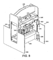
- the base plate 248 is mounted in a support frame 280 which has keyways 282 which engage with runners 284 mounted to the side plates 202, 204 as shown in Figure 8 .
- the vertical position of the frame 280 is adjustable by a mechanism which will be described further below in the context of the upper drum support mechanism.
- the frame 280 is moveable up and down in the runners by virtue of the pneumatic cylinders 286 mounted to the side plates 202, 204.
- the upper drums 232 are mounted to an upper base plate 290 in a similar manner to that described above.
- the base plate 290 is provided with pneumatic cylinders 292 for raising and lowering the moveable guide 294 of the base plate 290.
- the upper base plate 290 is mounted to an upper support frame 296, the upper support frame 296 is provided with keyways 298 for engagement with the guides 284.
- the upper frame 296 is moveable up and down along these guides by virtue of further pneumatic cylinders 300 fixed with respect to the side plates 202, 204.
- the upper surface 302 of the upper base plate 290 is provided with respective dovetail slides 304 which each receive a slidable, tapering block 306.
- the blocks 306 are moveable back and forth along the slides 304 by means of servo motors 308 which drive lead screws 309.
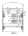
- the cross frame members 208 are provided with a pair of stepped wedge members 310 with which the tapered wedges 306 engage in use. This is shown, for example, in Figure 9 .
- the stepped wedge members 310 are moveable from side to side on the cross braces 208 such that different steps on each stepped wedge may align with the respective tapered wedges 306. This allows the vertical position of the upper support frame 296 and thus the upper drums 232 to be varied. This is necessary in order to compensate for different size drums.
- the tapered wedges 306 are held against the stepped wedges 310 by virtue of the pneumatic cylinders 300.
- the stepped wedges give a relatively coarse adjustment of the positions of the upper and lower support frames 296, 280.
- a finer adjustment can be obtained by means of the tapering wedges 306.
- the tapering wedges 306 can be moved backwards and forwards relative to the stepped wedges 310 thereby allowing a finer adjustment in the vertical position of the upper frame 296.
- the upper support frame 296 may be caused to tilt at an angle across the apparatus. This may be useful in adjusting the vertical position of one pair of drums relative to another.
- the lower support frame 280 is not provided with a movable tapering wedge mechanism as described above and is maintained perpendicular to the side plates 202, 204 throughout its adjustment through its stepped wedges.
- the conveyor mechanism of the present embodiment is different from that of the first embodiment. Rather than having separate upper infeed and outfeed conveyor belts, the present invention has a single upper conveyor 210,
- each conveyor comprises a lower conveyor belt 320 and an upper conveyor belt 322.
- the lower belt 320 is driven by drive wheel 220 and passes around a series of rollers in a similar manner to the belt 40 of the first embodiment.
- the upper belt 322 is not driven, other than by frictional engagement with the lower belt 320 or the blanks on the blower belt 320.
- the upper belt 322 also passes around a plurality of rollers, at least some of which 324 are spring loaded against the lower belt 320.
- the upper belt 322 has an infeed side 326 and an outfeed side 328
- the spring biasing force of the sprung rollers 324 can be adjusted buy a mechanism which is best seen in Figure 16 , which shows a detail of a part of Figure 15 with certain components removed for clarity.
- Each sprung roller 324 comprises a roller 330 mounted on an arm 332 which is pivotally mounted about an spindle axis 334.
- the arm 332 and thus the roller 330 are biased downwardly by a spring 336.
- An adjustment mechanism 338 comprises a pivotally mounted shaft 340 attached to an adjustment handle 342.
- the shaft has a cam surface 344 for engagement with a follower surface 346 provided at the upper end of the arm 332.
- the cam surface 344 has first and second flats 348, 350 provided at outer and inner diameters.
- the apparatus operates in the same manner as that of the first embodiment.
- the control system adjusts the angular positions of the drums 232, 236 to allow for the accurate embossing of the pattern on the blank approaching the drums 232, 236.
- one or more of the sprung rollers 324 adjacent the drums 232, 236 may be adjusted as described above so as to relieve the spring pressure on the upper conveyor belt 322 and thus allow the blanks to slip relative to the lower conveyor belt 320 as they pass through the drums, thereby allowing a fast throughput of blanks.
- the precise number of rollers 324 to be adjusted in this manner will depend on the particular blank and drum sizes. It will be understood that even though the upper belt is not biased against the lower belt in the drum region, the presence of the upper belt will stop the blank lifting from the lower conveyor belt 320, which might otherwise occur at high speeds.
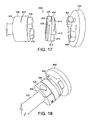
- an alternative coupling 400 comprises a drive plate 402 which is suitably bolted to the servo drive, a plastics coupling member 404 and a flexible coupling member 406 e.g. of steel or other metallic material.
- the drive plate 402 comprises a pair of drive teeth 408 which engage in a slot 410 formed between two ribs 412 projecting from a face 414 of the plastics coupling member 404.
- the flexible coupling member 406 comprises a pair of drive teeth 416 which engage in a slot 418 formed between two ribs 420 projecting from a second face 422 of the plastics coupling member 404.
- the flexible coupling member 406 further comprises a slot 424 which extends circumferentially for a limited distance, e.g. 180-270°, around the coupling member 406 to impart some flexibility to the coupling member 406.
- a limited distance e.g. 180-270°
- clamping means e.g. a clamping screw 430
- This coupling allows the embossing drum carriage 246 to be coupled very simply to the servo motor by sliding the carriage 246 into position and then locking it in position.
- the present invention may have many applications outside that field.
- the apparatus may of course operate with just one set of drums.
Landscapes
- Engineering & Computer Science (AREA)
- Mechanical Engineering (AREA)
- Health & Medical Sciences (AREA)
- Audiology, Speech & Language Pathology (AREA)
- General Health & Medical Sciences (AREA)
- Business, Economics & Management (AREA)
- Physics & Mathematics (AREA)
- Educational Administration (AREA)
- Educational Technology (AREA)
- General Physics & Mathematics (AREA)
- Theoretical Computer Science (AREA)
- Making Paper Articles (AREA)
- Machines For Manufacturing Corrugated Board In Mechanical Paper-Making Processes (AREA)
- Shaping Of Tube Ends By Bending Or Straightening (AREA)
Description
- The present invention relates to a method and apparatus for rotary embossing and in particular, but not exclusively, to a method and apparatus for embossing discrete sheet-like articles such as packaging blanks.
- In recent times, it has become necessary to provide information for the visually impaired on certain types of packaging, most significantly on pharmaceutical packaging. This is usually achieved by embossing Braille characters onto the packaging. A number of machines are used for this purpose. In a first type of machine, the pattern is embossed into the packaging blank at the same time as the creases and cuts are formed in the blank. This is, however, rather slow and requires the use of multiple embossing units on a single machine. In another type of machine, the embossing takes place after the blank has been creased and cut. Such machines tend to use rotary embossing.
- In a rotary embossing machine, male and complementary female formations are provided on opposed drums, between which the article to be embossed passes. The movement of the drums is synchronised, for example, by gearing, in order to ensure that the formations on the respective drums are in proper alignment. In the existing machinery, cut, creased and pre-folded blanks are fed to the embossing drums from a conveyor. The blanks are located accurately on the conveyor by flights. This ensures that the blanks are fed accurately to the embossing drums to ensure that the blanks are embossed in the correct position.
- However, a drawback with the above type of machine is that the speed of delivery of blanks to the embossing drums is somewhat limited. For example, typical feed speeds are in the region of 120 metres per minute. Higher feed speeds are desirable. Accordingly, the present invention seeks to provide an alternative method of and apparatus for embossing a blank which overcomes or mitigates the above problems.
-
DE-20 2005 017 869 U1 discloses an embossing apparatus having the features of the preamble of claim 1. A printed pattern and embossed pattern registration control system is disclosed inUS-A-3915090 . - From a first aspect, therefore, the invention provides an embossing apparatus as set forth in claim 1.
- The invention also extends to a method of embossing Braille set as set forth in
claim 12. - Thus the present invention, rather than relying upon blanks being fed to an embossing drum in a well defined position, as is the case where blanks are supplied by a flighted conveyor, senses individual blanks as they are fed to the embossing drum and compensates for any change in spacing between adjacent blanks which, if not corrected for, would lead to the pattern to be embossed being positioned incorrectly on the blank. The invention allows blanks to be fed to the embossing drum on conventional conveyors, at much higher speeds, leading to improved productivity.
- Preferably, co-operating male and female embossing drums are provided having complementary formations formed on each. In this event, the rotational position of both drums needs to be controlled such that the blank engages the embossing formation in the correct position.
- The position of the blank can be sensed by any suitable means. Such means may sense any suitable datum on the blank. The datum on the blank can be any feature on the blank, provided the position of that feature relative to the position of the desired embossing is known. For convenience, the datum may be the leading edge of the blank. The sensing means may comprise any suitable sensor, such as an optical sensing unit.
- The speed of the blank can most easily be sensed by determining the surface speed of the conveyor, as the blank moves with the surface of the conveyor without slipping. The surface speed of the conveyor can easily be determined from the rotational speed of a drive of the conveyor and the radial offset of the conveyor drive surface from the drive axis. An encoder may be provided on the drive shaft to provide information regarding the rotational speed of the drive.
- Knowing the speed of the blank and the position of a datum, the time taken for the blank to reach the embossing formation can be accurately calculated. Knowing this, and the rotational position of the embossing formation on the drum and the speed of rotation of the drum it is possible to determine where on the blank, relative to the datum the formation will engage the blank.
- The rotational position of the embossing formation does not need to be sensed as such, but can be determined by means such as an encoder which, once the initial position of the embossing formation is determined accurately, can be used to determine the formation's rotational position at later times.
- If it is determined that the embossing formation will not engage the blank in the correct position, then a rotational position of the drum can be adjusted to compensate for this.
- Advantageously, the adjustment is achieved using a servo motor drive for the drum, controlled by an appropriate servo control.
- The speed of rotation of the embossing drum is adjusted so as to affect the necessary compensation. Thus, if it is determined that the embossing formation will engage the blank ahead of the intended position, the speed of the drum may be decreased such as to bring the formation and blank into the desired relative positions. Similarly, if it is determined that the formation will engage the blank behind the intended position, the drum speed can be increased.
- In the preferred embodiment, both drums are driven by respective servo motors which are controlled independently by the control. In another arrangement, however, it would be possible to provide just a single servo motor which drives both drums through a suitable linkage. Two servo motors are preferred, however, as it reduces the inertial effects on the system.
- The conveyor and embossing drum are preferably provided in a unit which can be fitted to existing machinery. In addition, the unit preferably further comprises an out feed conveyor which conveys the embossed blank to subsequent processing stations.
- As is common in the conveying art, the infeed and outfeed conveyors may comprise a lower conveyor which receives a blank and an upper conveyor which is spring loaded against the lower conveyor so as to hold the blank firmly on the lower conveyor.
- In one embodiment, the infeed and outfeed conveyors comprise a common lower conveyor, with separate upper conveyors arranged on the infeed and outfeed sides of the embossing unit. The lower conveyor is preferably driven by a single input, which may be taken from adjacent parts of the machinery. Alternatively, the conveyor may be driven by a separate motor whose speed is synchronised with the speed of adjacent machinery. The upper conveyor, at least on the infeed side may be adjustable in position longitudinally of the apparatus to accommodate different sizes of blanks so that they can be accurately fed to the nip between the embossing drums.
- The above arrangement makes it possible for the blank not to be constrained by an upper conveyor in the region of the embossing drums. This is advantageous in that it permits the desired correction of drum position for a particular blank to occur while the preceding blank is still being embossed or is still held between the embossing drums. If the blanks were being held firmly between upper and lower conveyors while held between the drums, any relative movement between the drum surface and the conveyor (which runs at a constant speed) would lead to either compression or tension in the blank which could lead to buckling or tearing of the blank. The absence of upper restraint means that the blank can slip slightly on the lower conveyor to accommodate the relative movement. In the absence of such a feature, the system would have to configured only to effect a correction while no blank was between the embossing drums, which would mean leaving a larger gap between blanks. That would lead to slower blank through-put.
- In preferred embodiments of the invention, therefore, the adjustment of the rotational position of the embossing formation occurs while a preceding blank is still between the embossing drums and the infeed and outfeed conveyors are positioned or configured such as to permit relative movement between the blanks and the lower conveyor as the blanks pass between the drums,
- In an alternative embodiment to that described above with separate infeed and outfeed upper conveyors, common upper and lower infeed and outfeed conveyors may be provided. However, to allow for slippage of the blank relative to the lower conveyor, in a preferred arrangement, the biasing force exerted by the upper infeed conveyor section and possibly also the outfeed conveyor section against the corresponding lower conveyor sections is adjustable. This permits the spring force forcing the blank down onto the lower conveyor to be reduced or eliminated in the region of the embossing drums, thereby permitting slippage of the blank on the lower conveyor.
- This arrangement may be advantageous over the arrangement described earlier where there is no upper conveyor in the region of the embossing drums. Since although there is no significant clamping between the upper and lower conveyors, the upper conveyor does prevent the blank lifting, as might otherwise happen, particularly towards the edges of the blank.
- Typically the upper conveyor biasing arrangement comprises a plurality of spring loaded wheels acting against the back of the upper conveyor, and the adjustment can be effected by merely raising the wheels away from the conveyor, for example using a suitable cam mechanism.
- Preferably, more than one conveyor is provided across the width of the unit to provide sufficient support for the blank. Most preferably the conveyors are adjustable laterally so as to provide support in the appropriate position.
- The embossing drums are also preferably adjustable laterally of the apparatus. This allows the position of the drum to be adjusted to lay down the embossed pattern in a desired position on the blank.
- For example, a typical packaging blank comprises a number of panels hingedly connected together about crease lines. The invention will allow particular panels to be embossed as required. For example, face panels of the blank may be embossed. It is possible also to emboss say a glue panel in order to treat the surface thereof. This may potentially improve the adhesion of that panel to an adjacent panel.
- In one embodiment, embossing drum supports may be mounted on shafts extending laterally between the sides of the apparatus. The drive motor may be fixed to a side of the apparatus and have a drive shaft extending laterally across the apparatus such that irrespective of the lateral position of the drum it will be able to engage the drive shaft.
- In one embodiment, where respective drive motors are provided for the respective embossing rollers, the drive motors may be arranged on opposite sides of the apparatus in order to facilitate motor positioning.
- Alternatively, and preferably, each drum and its associated drive motor is mounted on a carriage which is adjustable in transversely of the apparatus on guides extending across the apparatus. Such an arrangement has the potential advantage that the drum and motor may be assembled onto the carriage away from the apparatus, thereby facilitating setting.
- It will be appreciated that more than one size of embossing drum may have to be used on a machine at different times, depending, for example, on the size of blank being embossed. Preferably therefore, means are provided to accommodate different drum sizes.
- In one preferred arrangement, therefore, the upper and lower embossing drums are mounted in vertically adjustable supports, preferably slidingly mounted in the apparatus.
- In one embodiment the respective support is engageable with an adjustable stop provided on the machine. Preferably the stop is formed as an adjustable wedge, such that depending on the position of the wedge, the support will engage with the stop at a higher or lower position. Of course, in an alternative embodiment, the wedge could instead be provided on the support and a static stop be provided on the machine
- The wedge may be mounted on the machine frame in any suitable manner, for example, in a sliding mount, or in a number of discrete positions.
- The wedge is preferably a stepped wedge which may be preferably in that each step may correspond to a particularly drum diameter thereby facilitating setting.
- The above arrangements are advantageous in their own right, so from a further aspect, the invention provides an embossing apparatus comprising a pair of supports for opposed embossing drums, said supports cooperating with the machine through being an adjustment wedge for adjusting the relative vertical positions of the supports.
- Preferably a pair of spaced apart adjustment wedges is provides for each drum support.
- The above described arrangement may potentially provide very accurate positioning of the drums. However, it will be appreciated that in use, some degree of fine adjustment may be needed to accommodate, for example the thickness of the blank material, wear in component parts etc. To accommodate this, at least one drum (and preferably only one) support preferably engages the aforementioned wedge through a further, fine adjustment wedge. This arrangement of wedge engaging wedge provides for a wide range of accurate adjustment.
- The fine adjustment wedge may be moved by any suitable means such as a lead screw.
- The embossing drum preferably comprises a drum body which receives an embossing plate around a peripheral surface thereof.
- The embossing plate may extend around the entire periphery of the drum or only a part thereof. A plurality of discrete plates may be mounted in desired circumferential positions on the drum.
- In the preferred embodiment, the embossing plate preferably comprises a chamfer extending along at least one longitudinal edge for engagement with a complementary formation on the drum. Preferably chamfers are provided on both longitudinal edges of the plate.
- In a preferred embodiment, the drum comprises a clamping disk which engages one face of the disk and engages over a chamfered edge of the embossing plate.
- The chamfer may be machined on to the plate during manufacture by any suitable process, for example by milling. In order to facilitate the manufacture, the plate may be attached to a support, with the machining extending into the support. The support may then be discarded. In a simple embodiment, the support may be a plastic plate or sheet and the plate may be secured to it in any convenient manner, for example by adhesive tape.
- The embossing drum may comprise any suitable number of embossing formations. For example, depending on the size of the blank being embossed, the drum may contain two, three or even more embossing patterns so that more than one blank is embossed per revolution of the embossing drum.
- It is also possible within the scope of the invention to provide a plurality of pairs of embossing drums in the unit to allow different regions of the blank to be embossed simultaneously. Thus, for example, more than one panel of a packaging blank may be embossed. In such arrangements, the drum pairs are preferably spaced laterally across the unit and are preferably arranged on a common drive spindles driven by the same motor or motors. Provided the drum pairs are correctly positioned one relative to the other when the machine is set up, they will maintain their proper relative rotational position such that the patterns embossed in the different positions maintain the correct relative positions.
- From a further aspect therefore, the invention provides a rotary embossing machine comprising a plurality of rotary embossing drums arranged on a common drive spindle.
- A preferred embodiment of the invention will now be described by way of example only with reference to the accompanying drawings in which:
-
Figure 1 shows a side view of an apparatus in accordance with the invention; -
Figure 2 shows a similar view toFigure 1 but with various components removed for clarity; -
Figure 3 shows an end view of the apparatus ofFigure 1 ; -
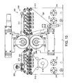
Figure 4 shows a top plan view of the apparatus ofFigure 1 ; -
Figure 5 shows schematically a control for the apparatus; -
Figure 6 shows an embossing drum for use in the apparatus ofFigure 1 ; -
Figure 7 shows an embossing plate for use in the embossing drum ofFigure 6 ; -
Figure 8 shows a perspective view of a second apparatus in accordance with the invention; -
Figure 9 shows a front view of the apparatus ofFigure 8 ; -
Figure 10 shows a side view of the apparatus ofFigure 8 ; -
Figure 11 shows the apparatus ofFigure 8 from a different perspective and having additional components; -
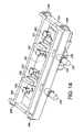
Figure 12 shows a subassembly of the apparatus ofFigure 8 ; -
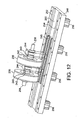
Figure 13 shows a further subassembly of the apparatus ofFigure 8 ; -
Figure 14 shows a yet further subassembly of the apparatus ofFigure 8 ; -
Figure 15 shows the conveyor belt arrangement of the apparatus ofFigure 8 ; -
Figure 16 shows an exploded detail ofFigure 15 ; -
Figure 17 shows an exploded view of an alternative coupling between an embossing drum and servo motor; and -
Figure 18 shows the coupling ofFigure 17 assembled. - Referring to
Figures 1 to 4 , a rotary embossing apparatus 2 comprises, in broad terms, an infeed conveyor 4, an outfeed conveyor 6 and arotary embossing unit 8 arranged between the infeed and outfeed conveyors 4, 6. - The unit 2 is arranged between upstream and downstream units not shown. The upstream unit typically will comprise a prefolding unit which takes cut and creased blanks from a magazine and prefolds them to facilitate subsequent gluing. The downstream unit is typically a folding and gluing unit.
- Returning to the unit 2, in more detail, the unit 2 comprises
side plates cross-braces side plate 10 are first andsecond spindles first spindle 20 are mounted afirst pulley 24 andsecond pulley 26. On thesecond spindle 22 are mounted first, second andthird pulleys first pulley 24 mounted onfirst spindle 20 receives drive from an adjacent downstream unit (not shown) through abelt 33 . The drive is transferred across the unit through the smaller diameter pulleys 26,28. The larger diameter pulley 30 on thesecond spindle 22 rotates with thesmaller diameter pulley 28 and provides drive through abelt 35 to an upstream unit (not shown). - The
innermost pulley 32 onspindle 22 is used to drive the infeed and outfeed conveyors 4,6. In particular, the pulley is connected by abelt 37 to afurther pulley 34, mounted on aspindle 36 which extends between theside plates spindle 36 are two belt drive assemblies including adrive belt pulley 38, although more such pulleys may be provided if required. Aconveyor belt 40 extends around thedrive pulley 38, around respective sets ofrollers tensioning roller 46 and guiderollers 48. The position of the drive pulleys 38 on thespindle 36 may be adjusted by looseningadjustment bolts 50. It will thus be seen that asingle belt 40 forms part of both the infeed and outfeed conveyors 4,6. - Arranged above the
respective drive belts 40 are upper andlower belt units belt 56 which travels around fourguide rollers 58 and which is spring loaded against thedrive belt 40 byspring rollers 60 provided in each unit. Theupper units upper belt units - The
embossing unit 8 comprises amale drum 70 and afemale drum 72. Themale drum 70 is mounted onto a shaft 74 for rotation therewith. Thefemale drum 72 is mounted onto a shaft 76 for rotation therewith. At one end the shaft 74 is supported by a bearing 78 in anend plate 80 which is moveable vertically relative to theside plate 12 by means of aturn screw arrangement 82. The other end of the shaft is coupled to theoutput shaft 84 of aservo motor 86 by means of acoupling sleeve 88. Theservo motor 86 is mounted to afurther end plate 90 which is also mounted moveably with respect to theside plate 10 by virtue of aturn screw arrangement 92. - Two
shafts side plates shafts Figure 1 , the drum supports 98, 100 are generally triangular in shape. Theupper drum 70 is located in the drum supports 98,100 by respective bearings 102,104. This mounting arrangement stabilises the position of the drum and counteracts any forces which may act on the drive shaft 74. - The lower,
female drum 72 is mounted in a similar manner. At one end the shaft 76 is supported by a bearing 78a in anend plate 80a. The other end of the shaft 76 is coupled to theoutput shaft 84a of aservo motor 86a by means of acoupling sleeve 88a. Theservo motor 86a is mounted to a further end plate 90a. Thelower drum 72 may be mounted vertically adjustable in the apparatus by virtue of turn screw arrangements not shown. - Two shafts 94a , 96a extend between the
side plates 80a, 90a. These shafts 94a, 96a serve to mount the lower drum supports 98a, 100a. As can be seen inFigure 1 , the drum supports 98a, 100a are generally triangular in shape. Thelower drum 72 is located in the drum supports 98a ,100a byrespective bearings - It will be noted that the
servo motor 86 which drives themale drum 70 and theservo motor 86a which drives thefemale drum 72 are arranged at opposite sides of the apparatus in order to facilitate their mounting on the apparatus.. - The drum supports 98, 100, 98a, 100a, can be moved along the
shafts hydraulic clamping fasteners - An
optical sensor 108 is mounted to the unit in a position shown schematically in the Figures at upstream of the embossing drums 70, 72. These sensors detect the leading edge of blank 110 as it passes between them and feed this information to a servo control 112 for the apparatus as will be described further below. - The control ensures that the blank 108 engages with the
drums Figure 4 . - The
servo control 110 comprises acontroller 120 which receives aninput signal 122 from theoptical sensor 108 when theleading edge 110 of the blank 106 is detected. Thecontroller 120 also receives asecond input 124 from anencoder 126 which is mounted on thespindle 36 of thelower elevator belt 40. Theinput 124 is representative of the rotary speed of thespindle 36. From thesignal 124, and knowing the diameter of thebelt drive pulley 50, thecontroller 120 can calculate the speed of theconveyor belt 40 and therefore the speed of the blank 110 which is travelling on thebelt 40. - The
controller 120 further receives athird input 128 from theservo motor 86, e.g. from an encoder associated with a shaft of themotor 86. The third input is representative of the rotational position of the drum and thus the embossing formation at the time the leading edge of the blank 110 is detected by thesensor 108. With this information and knowing the speed of theservo motor 86, which is derived from a further input 130 (or from the input 128), thecontroller 120 can calculate how long it will take for the blank 110 to engage with the embossing formation and whether this engagement will take place at the desired position. If thecontroller 120 calculates that it will not, then it sends anoutput signal 132 to the servo motor either increasing or decreasing the speed of the servo motor such that the embossing formation will engage the blank in the correct position. - As there is no upper conveyor belt in the region of the
drums lower conveyor belt 40. In fact, for the reasons explained in the introduction to this application it is preferred that the correction does take place while the preceding blank is still between the embossing drums 70, 72. - It will be understood that when the apparatus is first operated it will be necessary to register the correct position of the drum relative to the blank which can then be taken as a starting point for subsequent determination of the rotational position of the drum.
- Whilst
Figure 4 shows just a single servo motor being controlled in this manner, in the preferred embodiment both servo motors are controlled in this manner. - Turning now to
Figure 6 , adrum 70 is shown in an exploded view. Thedrum 70 comprises adrum body 150 having agroove 152 formed in itsperipheral surface 154. Theinner edge 156 of the groove is angled outwardly as shown in the detail A. Thegroove 152 receives anembossing plate 158 which is secured in position by aclamping collar 160 which locates over ashoulder 162 formed on thedrum body 150. Sixequispaced bolts 164 secure theclamping collar 160 to thedrum body 150. Theupper edge 166 of theclamping plate 160 is chamfered as shown detail B. - The
embossing plate 158 is formed with aBraille formation 168 on its external surface. As shown inFigure 7 , thelongitudinal edges drum body 150 and clamped by thecollar 160 they form a dovetail joint to firmly anchor theplate 158 on thedrum body 150. Registration means may be provided on thedrum body 150 and theplate 158 such that they are aligned correctly in the circumferential direction. - In manufacturing the
embossing plate 158, it may be attached to a suitable support, for example a plastic support and the chamferededges plate 158 whilst on that support. This considerably facilitates manufacture of the plate. - In use, therefore, blanks 110 (which are typically of cardboard, paperboard, plastics or other foldable sheet material) will be fed to the unit from an upstream unit where the blanks may have been prefolded to work creases to facilitate subsequent folding and gluing. The blanks are received by the infeed conveyor 4 and fed to the embossing unit 6. The leading edge of each blank will be sensed by the
optical sensor 104 and communicated to thecontrol 120. This determines, from the speed of the blank 106 and the rotational position and speed of the embossing drums 70, 72 whether the blanks will engage the embossing formations on the drums in the correct position. If they will not, the control will adjust the rotational speed of the drums to compensate for any estimated error. This happens for each and every blank. - After embossing, the embossed blanks are received by the outfeed conveyor 6 which will feed them to a downstream unit, for example a gluing and folding machine.
- Speeds of up to 400m/minute are achievable with the present invention which is a considerable improvement on existing machinery.
- The embossing drums 70, 72 may emboss any desired part of the blank 110 by being positioned in the appropriate lateral position in the unit. Thus, for example, the embossing drums 70, 72 may emboss a face panel 112 of the blank 110, or even a
glue panel 114 of the blank. - Moreover, more than one pair of embossing drums may be provided across the unit, mounted on further supports similar to those described above and driven by the
motors - A second embodiment of the invention is now described with reference to
Figures 8 to 16 . - As in the earlier embodiment, the embossing apparatus is intended to be arranged between upstream and downstream units, not shown. Certain features aspects of the apparatus, for example the sensing and control features are similar to those of the first embodiment and will not, therefore be described, but there are several significant differences, as will become apparent from the description below.
- The
apparatus 200 comprisesside plates plates Figures 11 and15 , the unit comprises a pair of transversely spaced in feed andoutfeed conveyors 210. The conveyors are supported onplates lower plates 212 are mounted for transverse sliding movement on a pair ofshafts 216 extending between theside plates belt drive shaft 218 also extends between theside plates conveyors 210 byrespective drive wheels 220 arranged on theshaft 218. Adrive motor 222 is arranged at one end of thedrive shaft 218. This is a different arrangement from the earlier embodiment where drive was effected through a coupling to adjacent machine units. - The lateral position of the
conveyor units 210 can be adjusted on theshafts 216 by means of adjustment screws 224. Further details of theconveyor units 210 will be given below. - The
apparatus 200 further comprises respective pairs of embossing drums 230. The construction of the drums per se is generally as described in the earlier embodiment, although they are supported in the apparatus in a different manner. In this regard, an upper pair ofmale drums 232 is mounted on anupper shaft 234 while a pair offemale drums 236 is mounted on alower shaft 238. Details of the lower drum arrangement are shown inFigures 12 and13 . - With reference to
Figure 12 , ashaft 238 passes through thedrums 236 which can be properly spaced apart on theshaft 238 by means, for example, of one ormore spacers 240. Eachdrum 236 is held in position on theshaft 238 by anETP clamp 242.Such clamps 242 are well known in the art and may not therefore be described further here. Theshaft 238 is supported by bearings in support blocks 244 which are mounted to acarriage 246. - The assembly of
shaft 238,drums 236 andcarriage 246 is mounted as a unit to abase plate 248. Thebase plate 248 comprises a dovetail profiledslideway 250 whose edges are defined byrails rail 252 is fixed relative to thebase plate 248 but theother rail 254 is moveable vertically with respect to thebase plate 248 by virtue of respectivepneumatic cylinders 256 mounted to the underside of thebase plate 248. - Turning now to
Figure 13 , theinboard end 258 of theshaft 238 is coupled to aservo motor 260 by virtue of acoupling 262. Thecoupling 262 comprises anOldham coupling 264 andETP clamp 266 attached to theOldham coupling 264. TheETP clamp 266 clamps down onto theshaft end 258 and into a bore on theOldham coupling 264 to secure the two components together. Ahousing 270 is provided around thecoupling 262 and is bolted to the front face of theservo motor 260. Thecoupling 262 is supported within thehousing 270 by a pair ofbearings 278. Thehousing 270 is provided with a dovetail at its lower end for engagement in theslideway 250. Ablock 272 mounted on alead screw 274 mounted to thebase plate 248 engages thehousing 270. - In order to set the correct lateral position of the
drums 236, thepneumatic cylinders 256 are extended so as to raise theside guide 254 to allow thecarriage 246 , to be mounted to thebase plate 248. Theshaft 238 can then be joined to theservo motor 260 to form a unitary assembly using theETP clamp 266. The desired lateral position of the drum/servomotor assembly can be obtained by rotation of thelead screw 274 which moves theblock 272 and thereby the drum/servo motor subassembly along thebase plate 248. When the subassembly is in the correct position, thecylinders 256 can be retracted so as to clamp down therail 254 against thecarriage 246 thereby securing thecarriage 246 in position on thebase plate 248. - To set the relative rotational position of the
drums 236 andmotor 260, analignment rod 279 can be passed through alignment openings (not shown) in thedrums 236 andhousing 270. - The
base plate 248 is mounted in asupport frame 280 which haskeyways 282 which engage withrunners 284 mounted to theside plates Figure 8 . The vertical position of theframe 280 is adjustable by a mechanism which will be described further below in the context of the upper drum support mechanism. Theframe 280 is moveable up and down in the runners by virtue of thepneumatic cylinders 286 mounted to theside plates - The
upper drums 232 are mounted to anupper base plate 290 in a similar manner to that described above. Thus, for example, as shown inFigure 14 , thebase plate 290 is provided withpneumatic cylinders 292 for raising and lowering themoveable guide 294 of thebase plate 290. Theupper base plate 290 is mounted to anupper support frame 296, theupper support frame 296 is provided withkeyways 298 for engagement with theguides 284. As can be seen inFigure 8 , theupper frame 296 is moveable up and down along these guides by virtue of furtherpneumatic cylinders 300 fixed with respect to theside plates - The
upper surface 302 of theupper base plate 290 is provided with respective dovetail slides 304 which each receive a slidable, taperingblock 306. Theblocks 306 are moveable back and forth along theslides 304 by means ofservo motors 308 which drive lead screws 309. - The
cross frame members 208 are provided with a pair of steppedwedge members 310 with which the taperedwedges 306 engage in use. This is shown, for example, inFigure 9 . The steppedwedge members 310 are moveable from side to side on the cross braces 208 such that different steps on each stepped wedge may align with the respective taperedwedges 306. This allows the vertical position of theupper support frame 296 and thus theupper drums 232 to be varied. This is necessary in order to compensate for different size drums. The taperedwedges 306 are held against the steppedwedges 310 by virtue of thepneumatic cylinders 300. - A similar arrangement is provided on the
lower base plate 248 so that the vertical positions of both the upper andlower drums - The stepped wedges give a relatively coarse adjustment of the positions of the upper and lower support frames 296, 280. A finer adjustment can be obtained by means of the tapering
wedges 306. In particular, by operating theservo motor 308, the taperingwedges 306 can be moved backwards and forwards relative to the steppedwedges 310 thereby allowing a finer adjustment in the vertical position of theupper frame 296. Furthermore, by simultaneously moving the respective taperingwedges 306 to different positions, theupper support frame 296 may be caused to tilt at an angle across the apparatus. This may be useful in adjusting the vertical position of one pair of drums relative to another. - The
lower support frame 280 is not provided with a movable tapering wedge mechanism as described above and is maintained perpendicular to theside plates - As discussed above, the conveyor mechanism of the present embodiment is different from that of the first embodiment. Rather than having separate upper infeed and outfeed conveyor belts, the present invention has a single
upper conveyor 210, - Referring to
Figure 15 , each conveyor comprises alower conveyor belt 320 and anupper conveyor belt 322. Thelower belt 320 is driven bydrive wheel 220 and passes around a series of rollers in a similar manner to thebelt 40 of the first embodiment. Theupper belt 322 is not driven, other than by frictional engagement with thelower belt 320 or the blanks on theblower belt 320. Theupper belt 322 also passes around a plurality of rollers, at least some of which 324 are spring loaded against thelower belt 320. Theupper belt 322 has aninfeed side 326 and anoutfeed side 328 - The spring biasing force of the sprung
rollers 324 can be adjusted buy a mechanism which is best seen inFigure 16 , which shows a detail of a part ofFigure 15 with certain components removed for clarity. - Each sprung
roller 324 comprises aroller 330 mounted on anarm 332 which is pivotally mounted about anspindle axis 334. Thearm 332 and thus theroller 330 are biased downwardly by aspring 336. - An
adjustment mechanism 338 comprises a pivotally mountedshaft 340 attached to anadjustment handle 342. The shaft has acam surface 344 for engagement with afollower surface 346 provided at the upper end of thearm 332. Thecam surface 344 has first andsecond flats - When the outer diameter
flat surface portion 348 engages thefollower surface 346, the follower surface is pushed down so as to rotate thearm 332 against the force of thespring 336, thereby lifting theroller 330 away from the back of theupper conveyor belt 322. When the inner diameter flat 350 engages thefollower surface 346, the roller arm is allowed to rotate down so as to allow theroller 330 to engage the back of theconveyor belt 322. - The effect of this will now be explained in the context of the operation of the apparatus.
- In essence the apparatus operates in the same manner as that of the first embodiment. Thus, as blanks are moved through the apparatus on the
conveyors 210, the control system adjusts the angular positions of thedrums drums rollers 324 adjacent thedrums upper conveyor belt 322 and thus allow the blanks to slip relative to thelower conveyor belt 320 as they pass through the drums, thereby allowing a fast throughput of blanks. The precise number ofrollers 324 to be adjusted in this manner will depend on the particular blank and drum sizes. It will be understood that even though the upper belt is not biased against the lower belt in the drum region, the presence of the upper belt will stop the blank lifting from thelower conveyor belt 320, which might otherwise occur at high speeds. - Of course modifications may be made to the embodiments described above without departing from the scope of the invention. For example, an alternative form of coupling may be provided between the embossing drums and their servo motor drives.
- As shown in
Figure 17 , analternative coupling 400 comprises adrive plate 402 which is suitably bolted to the servo drive, aplastics coupling member 404 and aflexible coupling member 406 e.g. of steel or other metallic material.. Thedrive plate 402 comprises a pair ofdrive teeth 408 which engage in aslot 410 formed between tworibs 412 projecting from aface 414 of theplastics coupling member 404. Theflexible coupling member 406 comprises a pair ofdrive teeth 416 which engage in a slot 418 formed between tworibs 420 projecting from asecond face 422 of theplastics coupling member 404. Theflexible coupling member 406 further comprises aslot 424 which extends circumferentially for a limited distance, e.g. 180-270°, around thecoupling member 406 to impart some flexibility to thecoupling member 406. As shown inFigure 18 , thepart 426 of thecoupling member 406 behind theslot 424 is provided with a further slot 428 and clamping means, e.g. a clampingscrew 430, for clamping the flexible coupling onto the shaft 234,238. - This coupling allows the
embossing drum carriage 246 to be coupled very simply to the servo motor by sliding thecarriage 246 into position and then locking it in position. - While intended primarily for embossing packaging, the present invention may have many applications outside that field.
- Also, while the embodiments described show two sets of embossing drums, the apparatus may of course operate with just one set of drums.
Claims (15)
- An embossing apparatus (2) comprising:a rotary embossing drum (70,72) driven by a motor (86) and having a Braille embossing formation (168);a conveyor (4) for feeding blanks (110) to the embossing drum (70,72); anda control, characterised in that:said control comprises:means responsive to a sensed position and speed of the blank (110) and a sensed position and speed of the drum (70,72) for applying an correction to the rotational position of the drum (70,72) by adjusting the speed of rotation of the embossing drum (70,72) such that the blank (110) will engage the embossing formation in the correct position as it travels past the formation (168).
- An embossing apparatus as claimed in claim 1 comprising co-operating male and female embossing drums (70,72) having complementary formations formed on each.
- An embossing apparatus as claimed in claim 1 or 2 comprising means (108) for sensing the position of the blank (110), for example leading edge of the blank (110).
- An embossing apparatus as claimed in any preceding claim wherein said means for applying a positional correction comprises a servo motor (86) and a servo control.
- An embossing apparatus as claimed in claim 4 wherein two cooperating embossing drums (70,72) are driven by respective servo motors.
- An embossing apparatus as claimed in any preceding claim wherein the control of the apparatus is configured to adjust the rotational position of the embossing formation (168) occurs while a preceding blank (110) is still between the embossing drums (70,72) and the conveyor (4) is positioned or configured such as to permit relative movement between the preceding blanks (110) and the conveyor (4) as the preceding blank pass between the drums (70,72).
- An embossing apparatus as claimed in any preceding claim comprising infeed and outfeed conveyors (4,6) which comprise a common lower conveyor (40), with separate upper conveyors (52,54) arranged on the infeed and outfeed sides of the embossing unit.
- An embossing apparatus as claimed in any of claims 1 to 6 comprising common upper and lower infeed and outfeed conveyors (322,320), and wherein a biasing force exerted by the upper infeed conveyor section and possibly also the outfeed conveyor section against the corresponding lower conveyor sections is adjustable, for example wherein the upper conveyor biasing arrangement comprises a plurality of spring loaded wheels (324) acting against the back of the upper conveyor (322), and the adjustment is effected by raising the wheels (324) away from the conveyor (322).
- An embossing apparatus as claimed in any preceding claim wherein the embossing drum or drums (236) are adjustable transversely of the apparatus, for example wherein the or each embossing drum (236) and its associated drive motor is mounted on a carriage (246) which is adjustable transversely of the apparatus on guides (250) extending across the apparatus.
- An embossing apparatus as claimed in any preceding claim wherein upper and lower embossing drums (70,72) are mounted in vertically adjustable supports, preferably slidingly mounted in the apparatus.
- An embossing apparatus as claimed in any preceding claim comprising a plurality of pairs of embossing drums (70,72), wherein the pairs of embossing drums (70,72) are spaced laterally across the apparatus and wherein the pairs of embossing drums (70,72) are arranged on common drive spindles driven by the same motor or motors.
- A method of embossing Braille on a blank (110) comprising:feeding a blank (110) to an embossing drum (70,72);sensing a datum on the blank (110);determining the speed of the blank (110);determining the speed and angular position of an embossing formation (168) on the embossing drum;determining whether said blank (110) will engage with said embossing formation (168) in a desired position; andin the event that it is determined that the blank (110) will not engage the embossing formation (168) in the desired position, adjusting a rotational position of the drum (70,72) by adjusting the speed of rotation of the embossing drum (70,72) such that it will.
- A method as claimed in claim 12 comprising calculating the time taken for the sensed blank (110) to reach the embossing formation (168), and using that time, the rotational position of the embossing formation (168) on the drum (70,72) and the speed of rotation of the drum (70,72) determining where on the blank (110), relative to the datum, the formation will engage the blank (70,72).
- A method of embossing as claimed in claim 12 or 13 wherein the correction of drum position is effected while a preceding blank (110) is still being embossed or is still being held between the embossing drums (70,72).
- A method of embossing as claim 14 wherein blanks (110) are fed to and/or removed from the embossing drums (70,72) on a conveyor or conveyors (4,6) in such a way that the blanks may slip on the conveyor or conveyors (4,6) to accommodate any difference in surface speed between the conveyors (4,6) and the blank (110) during the adjustment of the drum position.
Applications Claiming Priority (3)
| Application Number | Priority Date | Filing Date | Title |
|---|---|---|---|
| GBGB0705260.8A GB0705260D0 (en) | 2007-03-19 | 2007-03-19 | Rotary embossing |
| GBGB0723215.0A GB0723215D0 (en) | 2007-03-19 | 2007-11-27 | Rotary embossing |
| PCT/GB2008/000982 WO2008114018A2 (en) | 2007-03-19 | 2008-03-19 | Rotary embossing |
Publications (2)
| Publication Number | Publication Date |
|---|---|
| EP2139672A2 EP2139672A2 (en) | 2010-01-06 |
| EP2139672B1 true EP2139672B1 (en) | 2014-07-09 |
Family
ID=38008698
Family Applications (1)
| Application Number | Title | Priority Date | Filing Date |
|---|---|---|---|
| EP08718819.9A Not-in-force EP2139672B1 (en) | 2007-03-19 | 2008-03-19 | Rotary embossing |
Country Status (4)
| Country | Link |
|---|---|
| US (1) | US20100236431A1 (en) |
| EP (1) | EP2139672B1 (en) |
| GB (2) | GB0705260D0 (en) |
| WO (1) | WO2008114018A2 (en) |
Families Citing this family (13)
| Publication number | Priority date | Publication date | Assignee | Title |
|---|---|---|---|---|
| GB0817509D0 (en) * | 2008-09-24 | 2008-10-29 | Chesapeake Plc | Rotary embossing |
| EP2422969B1 (en) * | 2010-08-31 | 2013-09-11 | Heidelberger Druckmaschinen AG | Folding box gluing machine |
| IT1401997B1 (en) * | 2010-09-30 | 2013-08-28 | Pro Form S R L | METHOD AND APPARATUS FOR THE PRODUCTION OF MATRICES FOR THE EMBOSSING OF BRAILLE CHARACTERS, AND MATRICES SO OBTAINED |
| DE102011116294A1 (en) * | 2011-10-18 | 2013-04-18 | Heidelberger Druckmaschinen Ag | Method for operating a device for embossing |
| DE102012019372B4 (en) | 2011-10-26 | 2025-03-13 | Masterwork Machinery Co., Ltd. | Method for embossing products with a rotary embossing device |
| EP3050684B1 (en) | 2011-11-10 | 2017-08-16 | Packsize LLC | Elevated converting machine with outfeed guide |
| DK2687383T3 (en) * | 2012-07-18 | 2016-02-15 | Ardagh Mp Group Netherlands Bv | Embossing the flat metal blank (method and apparatus) |
| WO2016140385A1 (en) * | 2015-03-05 | 2016-09-09 | 에이스기계(주) | Apparatus for transferring and processing blank |
| CN106846991B (en) * | 2017-03-30 | 2022-08-19 | 安庆师范大学 | Touch braille and graphic display device |
| WO2019246344A1 (en) | 2018-06-21 | 2019-12-26 | Packsize Llc | Packaging machine and systems |
| CN109693414B (en) * | 2019-01-25 | 2021-04-16 | 天津市康盛纸制品有限公司 | Paperboard spiral transverse cutting machine |
| US11701854B2 (en) * | 2019-03-14 | 2023-07-18 | Packsize Llc | Packaging machine and systems |
| CN115302848B (en) * | 2022-08-16 | 2023-07-21 | 江苏惠中包装有限公司 | Intelligent production device and method for corrugated paper packaging box |
Family Cites Families (9)
| Publication number | Priority date | Publication date | Assignee | Title |
|---|---|---|---|---|
| US3166008A (en) * | 1962-07-26 | 1965-01-19 | Anton N Lewandoski | Apparatus for impressing type face |
| US3915090A (en) | 1973-03-21 | 1975-10-28 | Armstrong Cork Co | Printed pattern and embossed pattern registration control system |
| US4116594A (en) * | 1975-12-12 | 1978-09-26 | Magna-Graphics Corporation | Embossing apparatus having magnetic roller and flexible embossing plates therefor |
| EP0857105A4 (en) * | 1995-10-23 | 2000-12-06 | Lawrence Paper Co | Box blank printer/slotter apparatus |
| DE10008215B4 (en) * | 2000-02-23 | 2013-03-28 | Manroland Web Systems Gmbh | Printing unit for a rotary printing press with cross slide |
| DE10141035A1 (en) * | 2001-08-22 | 2003-03-20 | Nexpress Solutions Llc | Method and printing machine for determining register errors |
| DE10333626A1 (en) * | 2003-07-24 | 2005-02-17 | Robert Bürkle GmbH | Device for printing on flat workpieces |
| DE202005017869U1 (en) * | 2005-11-16 | 2006-07-13 | Rosas Wolf, David | Single copy feeder and transport system for producing a folded printed box for the pharmaceutical industry comprises a feeder disposed with a register control unit via a servo drive |
| ITBO20060292A1 (en) * | 2006-04-14 | 2007-10-15 | Tech S R L S | EMBOSSER GROUP WITH LOGOS FOR PRODUCTS SUCH AS HANDCUFFS, NAPKINS AND THE LIKE. |
-
2007
- 2007-03-19 GB GBGB0705260.8A patent/GB0705260D0/en not_active Ceased
- 2007-11-27 GB GBGB0723215.0A patent/GB0723215D0/en not_active Ceased
-
2008
- 2008-03-19 US US12/532,061 patent/US20100236431A1/en not_active Abandoned
- 2008-03-19 WO PCT/GB2008/000982 patent/WO2008114018A2/en not_active Ceased
- 2008-03-19 EP EP08718819.9A patent/EP2139672B1/en not_active Not-in-force
Also Published As
| Publication number | Publication date |
|---|---|
| WO2008114018A2 (en) | 2008-09-25 |
| GB0723215D0 (en) | 2008-01-09 |
| US20100236431A1 (en) | 2010-09-23 |
| GB0705260D0 (en) | 2007-04-25 |
| WO2008114018A3 (en) | 2008-12-24 |
| EP2139672A2 (en) | 2010-01-06 |
Similar Documents
| Publication | Publication Date | Title |
|---|---|---|
| EP2139672B1 (en) | Rotary embossing | |
| EP2172329B1 (en) | Rotary embossing | |
| US5383392A (en) | Sheet registration control | |
| US5827162A (en) | Folder/gluer machine for paperboard blanks | |
| EP2818312B1 (en) | Sheet folding device and carton former | |
| US8196502B2 (en) | Device for the rotative scoring of flat printed products | |
| EP3450156B1 (en) | Sheet folding device and box-making machine | |
| US8960059B2 (en) | Variable folding system comprising linear drives, especially for printing machines | |
| US5606913A (en) | Sheet registration control | |
| US8915497B2 (en) | Method and apparatus for sheet and carton blank aligning using caster effect | |
| JP3824997B2 (en) | Apparatus and method for sheet alignment | |
| IL257250A (en) | Methods for creasing and cutting sheet materials | |
| US7398872B2 (en) | Device for aligning plate-like workpieces in a machine processing them | |
| US6773384B2 (en) | Sheet processing machine for making packages | |
| US8322962B2 (en) | Methods and apparatus to score book covers | |
| CN218535782U (en) | Deviation-correcting adjusting type paperboard grooving machine | |
| US20130168922A1 (en) | Method and apparatus for sheet and carton blank aligning | |
| CN115648713A (en) | Deviation-correcting adjusting type paperboard grooving machine | |
| JP7449719B2 (en) | Slitter device, slitter head positioning method, and box making machine | |
| WO2008042933A1 (en) | Sheet feed method and apparatus | |
| JP7355540B2 (en) | Saddle stitcher for printed products | |
| GB2620889A (en) | A mailer forming apparatus and method of forming | |
| WO2009050272A1 (en) | Unit and method for final folding in in-line manufacturing of corrugated board boxes |
Legal Events
| Date | Code | Title | Description |
|---|---|---|---|
| PUAI | Public reference made under article 153(3) epc to a published international application that has entered the european phase |
Free format text: ORIGINAL CODE: 0009012 |
|
| 17P | Request for examination filed |
Effective date: 20091015 |
|
| AK | Designated contracting states |
Kind code of ref document: A2 Designated state(s): AT BE BG CH CY CZ DE DK EE ES FI FR GB GR HR HU IE IS IT LI LT LU LV MC MT NL NO PL PT RO SE SI SK TR |
|
| 17Q | First examination report despatched |
Effective date: 20101013 |
|
| DAX | Request for extension of the european patent (deleted) | ||
| GRAP | Despatch of communication of intention to grant a patent |
Free format text: ORIGINAL CODE: EPIDOSNIGR1 |
|
| INTG | Intention to grant announced |
Effective date: 20130827 |
|
| GRAP | Despatch of communication of intention to grant a patent |
Free format text: ORIGINAL CODE: EPIDOSNIGR1 |
|
| INTG | Intention to grant announced |
Effective date: 20140117 |
|
| GRAS | Grant fee paid |
Free format text: ORIGINAL CODE: EPIDOSNIGR3 |
|
| GRAA | (expected) grant |
Free format text: ORIGINAL CODE: 0009210 |
|
| AK | Designated contracting states |
Kind code of ref document: B1 Designated state(s): AT BE BG CH CY CZ DE DK EE ES FI FR GB GR HR HU IE IS IT LI LT LU LV MC MT NL NO PL PT RO SE SI SK TR |
|
| RAP1 | Party data changed (applicant data changed or rights of an application transferred) |
Owner name: CHESAPEAKE LIMITED |
|
| REG | Reference to a national code |
Ref country code: GB Ref legal event code: FG4D |
|
| REG | Reference to a national code |
Ref country code: AT Ref legal event code: REF Ref document number: 676419 Country of ref document: AT Kind code of ref document: T Effective date: 20140715 Ref country code: CH Ref legal event code: EP |
|
| REG | Reference to a national code |
Ref country code: IE Ref legal event code: FG4D |
|
| REG | Reference to a national code |
Ref country code: DE Ref legal event code: R096 Ref document number: 602008033194 Country of ref document: DE Effective date: 20140821 |
|
| REG | Reference to a national code |
Ref country code: AT Ref legal event code: MK05 Ref document number: 676419 Country of ref document: AT Kind code of ref document: T Effective date: 20140709 |
|
| REG | Reference to a national code |
Ref country code: NL Ref legal event code: VDEP Effective date: 20140709 |
|
| REG | Reference to a national code |
Ref country code: LT Ref legal event code: MG4D |
|
| PG25 | Lapsed in a contracting state [announced via postgrant information from national office to epo] |
Ref country code: ES Free format text: LAPSE BECAUSE OF FAILURE TO SUBMIT A TRANSLATION OF THE DESCRIPTION OR TO PAY THE FEE WITHIN THE PRESCRIBED TIME-LIMIT Effective date: 20140709 Ref country code: SE Free format text: LAPSE BECAUSE OF FAILURE TO SUBMIT A TRANSLATION OF THE DESCRIPTION OR TO PAY THE FEE WITHIN THE PRESCRIBED TIME-LIMIT Effective date: 20140709 Ref country code: BG Free format text: LAPSE BECAUSE OF FAILURE TO SUBMIT A TRANSLATION OF THE DESCRIPTION OR TO PAY THE FEE WITHIN THE PRESCRIBED TIME-LIMIT Effective date: 20141009 Ref country code: GR Free format text: LAPSE BECAUSE OF FAILURE TO SUBMIT A TRANSLATION OF THE DESCRIPTION OR TO PAY THE FEE WITHIN THE PRESCRIBED TIME-LIMIT Effective date: 20141010 Ref country code: NO Free format text: LAPSE BECAUSE OF FAILURE TO SUBMIT A TRANSLATION OF THE DESCRIPTION OR TO PAY THE FEE WITHIN THE PRESCRIBED TIME-LIMIT Effective date: 20141009 Ref country code: FI Free format text: LAPSE BECAUSE OF FAILURE TO SUBMIT A TRANSLATION OF THE DESCRIPTION OR TO PAY THE FEE WITHIN THE PRESCRIBED TIME-LIMIT Effective date: 20140709 Ref country code: PT Free format text: LAPSE BECAUSE OF FAILURE TO SUBMIT A TRANSLATION OF THE DESCRIPTION OR TO PAY THE FEE WITHIN THE PRESCRIBED TIME-LIMIT Effective date: 20141110 Ref country code: LT Free format text: LAPSE BECAUSE OF FAILURE TO SUBMIT A TRANSLATION OF THE DESCRIPTION OR TO PAY THE FEE WITHIN THE PRESCRIBED TIME-LIMIT Effective date: 20140709 |
|
| PG25 | Lapsed in a contracting state [announced via postgrant information from national office to epo] |
Ref country code: CY Free format text: LAPSE BECAUSE OF FAILURE TO SUBMIT A TRANSLATION OF THE DESCRIPTION OR TO PAY THE FEE WITHIN THE PRESCRIBED TIME-LIMIT Effective date: 20140709 Ref country code: HR Free format text: LAPSE BECAUSE OF FAILURE TO SUBMIT A TRANSLATION OF THE DESCRIPTION OR TO PAY THE FEE WITHIN THE PRESCRIBED TIME-LIMIT Effective date: 20140709 Ref country code: NL Free format text: LAPSE BECAUSE OF FAILURE TO SUBMIT A TRANSLATION OF THE DESCRIPTION OR TO PAY THE FEE WITHIN THE PRESCRIBED TIME-LIMIT Effective date: 20140709 Ref country code: PL Free format text: LAPSE BECAUSE OF FAILURE TO SUBMIT A TRANSLATION OF THE DESCRIPTION OR TO PAY THE FEE WITHIN THE PRESCRIBED TIME-LIMIT Effective date: 20140709 Ref country code: IS Free format text: LAPSE BECAUSE OF FAILURE TO SUBMIT A TRANSLATION OF THE DESCRIPTION OR TO PAY THE FEE WITHIN THE PRESCRIBED TIME-LIMIT Effective date: 20141109 Ref country code: AT Free format text: LAPSE BECAUSE OF FAILURE TO SUBMIT A TRANSLATION OF THE DESCRIPTION OR TO PAY THE FEE WITHIN THE PRESCRIBED TIME-LIMIT Effective date: 20140709 Ref country code: LV Free format text: LAPSE BECAUSE OF FAILURE TO SUBMIT A TRANSLATION OF THE DESCRIPTION OR TO PAY THE FEE WITHIN THE PRESCRIBED TIME-LIMIT Effective date: 20140709 |
|
| REG | Reference to a national code |
Ref country code: DE Ref legal event code: R097 Ref document number: 602008033194 Country of ref document: DE |
|
| PG25 | Lapsed in a contracting state [announced via postgrant information from national office to epo] |
Ref country code: SK Free format text: LAPSE BECAUSE OF FAILURE TO SUBMIT A TRANSLATION OF THE DESCRIPTION OR TO PAY THE FEE WITHIN THE PRESCRIBED TIME-LIMIT Effective date: 20140709 Ref country code: IT Free format text: LAPSE BECAUSE OF FAILURE TO SUBMIT A TRANSLATION OF THE DESCRIPTION OR TO PAY THE FEE WITHIN THE PRESCRIBED TIME-LIMIT Effective date: 20140709 Ref country code: RO Free format text: LAPSE BECAUSE OF FAILURE TO SUBMIT A TRANSLATION OF THE DESCRIPTION OR TO PAY THE FEE WITHIN THE PRESCRIBED TIME-LIMIT Effective date: 20140709 Ref country code: DK Free format text: LAPSE BECAUSE OF FAILURE TO SUBMIT A TRANSLATION OF THE DESCRIPTION OR TO PAY THE FEE WITHIN THE PRESCRIBED TIME-LIMIT Effective date: 20140709 Ref country code: CZ Free format text: LAPSE BECAUSE OF FAILURE TO SUBMIT A TRANSLATION OF THE DESCRIPTION OR TO PAY THE FEE WITHIN THE PRESCRIBED TIME-LIMIT Effective date: 20140709 Ref country code: EE Free format text: LAPSE BECAUSE OF FAILURE TO SUBMIT A TRANSLATION OF THE DESCRIPTION OR TO PAY THE FEE WITHIN THE PRESCRIBED TIME-LIMIT Effective date: 20140709 |
|
| PLBE | No opposition filed within time limit |
Free format text: ORIGINAL CODE: 0009261 |
|
| STAA | Information on the status of an ep patent application or granted ep patent |
Free format text: STATUS: NO OPPOSITION FILED WITHIN TIME LIMIT |
|
| 26N | No opposition filed |
Effective date: 20150410 |
|
| PG25 | Lapsed in a contracting state [announced via postgrant information from national office to epo] |
Ref country code: MC Free format text: LAPSE BECAUSE OF FAILURE TO SUBMIT A TRANSLATION OF THE DESCRIPTION OR TO PAY THE FEE WITHIN THE PRESCRIBED TIME-LIMIT Effective date: 20140709 Ref country code: LU Free format text: LAPSE BECAUSE OF FAILURE TO SUBMIT A TRANSLATION OF THE DESCRIPTION OR TO PAY THE FEE WITHIN THE PRESCRIBED TIME-LIMIT Effective date: 20150319 |
|
| REG | Reference to a national code |
Ref country code: CH Ref legal event code: PL |
|
| PG25 | Lapsed in a contracting state [announced via postgrant information from national office to epo] |
Ref country code: SI Free format text: LAPSE BECAUSE OF FAILURE TO SUBMIT A TRANSLATION OF THE DESCRIPTION OR TO PAY THE FEE WITHIN THE PRESCRIBED TIME-LIMIT Effective date: 20140709 |
|
| PG25 | Lapsed in a contracting state [announced via postgrant information from national office to epo] |
Ref country code: LI Free format text: LAPSE BECAUSE OF NON-PAYMENT OF DUE FEES Effective date: 20150331 Ref country code: CH Free format text: LAPSE BECAUSE OF NON-PAYMENT OF DUE FEES Effective date: 20150331 |
|
| REG | Reference to a national code |
Ref country code: FR Ref legal event code: PLFP Year of fee payment: 9 |
|
| PG25 | Lapsed in a contracting state [announced via postgrant information from national office to epo] |
Ref country code: BE Free format text: LAPSE BECAUSE OF FAILURE TO SUBMIT A TRANSLATION OF THE DESCRIPTION OR TO PAY THE FEE WITHIN THE PRESCRIBED TIME-LIMIT Effective date: 20140709 |
|
| REG | Reference to a national code |
Ref country code: DE Ref legal event code: R079 Ref document number: 602008033194 Country of ref document: DE Free format text: PREVIOUS MAIN CLASS: B31B0001040000 Ipc: B31B0050040000 |
|
| PG25 | Lapsed in a contracting state [announced via postgrant information from national office to epo] |
Ref country code: MT Free format text: LAPSE BECAUSE OF FAILURE TO SUBMIT A TRANSLATION OF THE DESCRIPTION OR TO PAY THE FEE WITHIN THE PRESCRIBED TIME-LIMIT Effective date: 20140709 |
|
| REG | Reference to a national code |
Ref country code: FR Ref legal event code: PLFP Year of fee payment: 10 |
|
| PG25 | Lapsed in a contracting state [announced via postgrant information from national office to epo] |
Ref country code: HU Free format text: LAPSE BECAUSE OF FAILURE TO SUBMIT A TRANSLATION OF THE DESCRIPTION OR TO PAY THE FEE WITHIN THE PRESCRIBED TIME-LIMIT; INVALID AB INITIO Effective date: 20080319 |
|
| PG25 | Lapsed in a contracting state [announced via postgrant information from national office to epo] |
Ref country code: TR Free format text: LAPSE BECAUSE OF FAILURE TO SUBMIT A TRANSLATION OF THE DESCRIPTION OR TO PAY THE FEE WITHIN THE PRESCRIBED TIME-LIMIT Effective date: 20140709 |
|
| REG | Reference to a national code |
Ref country code: FR Ref legal event code: PLFP Year of fee payment: 11 |
|
| REG | Reference to a national code |
Ref country code: DE Ref legal event code: R082 Ref document number: 602008033194 Country of ref document: DE |
|
| PGFP | Annual fee paid to national office [announced via postgrant information from national office to epo] |
Ref country code: IE Payment date: 20220328 Year of fee payment: 15 Ref country code: GB Payment date: 20220328 Year of fee payment: 15 Ref country code: DE Payment date: 20220329 Year of fee payment: 15 |
|
| PGFP | Annual fee paid to national office [announced via postgrant information from national office to epo] |
Ref country code: FR Payment date: 20220325 Year of fee payment: 15 |
|
| REG | Reference to a national code |
Ref country code: DE Ref legal event code: R119 Ref document number: 602008033194 Country of ref document: DE |
|
| GBPC | Gb: european patent ceased through non-payment of renewal fee |
Effective date: 20230319 |
|
| REG | Reference to a national code |
Ref country code: IE Ref legal event code: MM4A |
|
| PG25 | Lapsed in a contracting state [announced via postgrant information from national office to epo] |
Ref country code: GB Free format text: LAPSE BECAUSE OF NON-PAYMENT OF DUE FEES Effective date: 20230319 |
|
| PG25 | Lapsed in a contracting state [announced via postgrant information from national office to epo] |
Ref country code: IE Free format text: LAPSE BECAUSE OF NON-PAYMENT OF DUE FEES Effective date: 20230319 Ref country code: GB Free format text: LAPSE BECAUSE OF NON-PAYMENT OF DUE FEES Effective date: 20230319 Ref country code: FR Free format text: LAPSE BECAUSE OF NON-PAYMENT OF DUE FEES Effective date: 20230331 Ref country code: DE Free format text: LAPSE BECAUSE OF NON-PAYMENT OF DUE FEES Effective date: 20231003 |