EP2139436B1 - Method of assembling a catheter having guidewire channel - Google Patents
Method of assembling a catheter having guidewire channel Download PDFInfo
- Publication number
- EP2139436B1 EP2139436B1 EP08779580.3A EP08779580A EP2139436B1 EP 2139436 B1 EP2139436 B1 EP 2139436B1 EP 08779580 A EP08779580 A EP 08779580A EP 2139436 B1 EP2139436 B1 EP 2139436B1
- Authority
- EP
- European Patent Office
- Prior art keywords
- catheter
- channel
- guidewire
- main body
- stent
- Prior art date
- Legal status (The legal status is an assumption and is not a legal conclusion. Google has not performed a legal analysis and makes no representation as to the accuracy of the status listed.)
- Active
Links
Images


Classifications
-
- A—HUMAN NECESSITIES
- A61—MEDICAL OR VETERINARY SCIENCE; HYGIENE
- A61F—FILTERS IMPLANTABLE INTO BLOOD VESSELS; PROSTHESES; DEVICES PROVIDING PATENCY TO, OR PREVENTING COLLAPSING OF, TUBULAR STRUCTURES OF THE BODY, e.g. STENTS; ORTHOPAEDIC, NURSING OR CONTRACEPTIVE DEVICES; FOMENTATION; TREATMENT OR PROTECTION OF EYES OR EARS; BANDAGES, DRESSINGS OR ABSORBENT PADS; FIRST-AID KITS
- A61F2/00—Filters implantable into blood vessels; Prostheses, i.e. artificial substitutes or replacements for parts of the body; Appliances for connecting them with the body; Devices providing patency to, or preventing collapsing of, tubular structures of the body, e.g. stents
- A61F2/95—Instruments specially adapted for placement or removal of stents or stent-grafts
- A61F2/962—Instruments specially adapted for placement or removal of stents or stent-grafts having an outer sleeve
- A61F2/97—Instruments specially adapted for placement or removal of stents or stent-grafts having an outer sleeve the outer sleeve being splittable
-
- A—HUMAN NECESSITIES
- A61—MEDICAL OR VETERINARY SCIENCE; HYGIENE
- A61F—FILTERS IMPLANTABLE INTO BLOOD VESSELS; PROSTHESES; DEVICES PROVIDING PATENCY TO, OR PREVENTING COLLAPSING OF, TUBULAR STRUCTURES OF THE BODY, e.g. STENTS; ORTHOPAEDIC, NURSING OR CONTRACEPTIVE DEVICES; FOMENTATION; TREATMENT OR PROTECTION OF EYES OR EARS; BANDAGES, DRESSINGS OR ABSORBENT PADS; FIRST-AID KITS
- A61F2/00—Filters implantable into blood vessels; Prostheses, i.e. artificial substitutes or replacements for parts of the body; Appliances for connecting them with the body; Devices providing patency to, or preventing collapsing of, tubular structures of the body, e.g. stents
- A61F2/02—Prostheses implantable into the body
- A61F2/04—Hollow or tubular parts of organs, e.g. bladders, tracheae, bronchi or bile ducts
- A61F2/06—Blood vessels
- A61F2/07—Stent-grafts
-
- A—HUMAN NECESSITIES
- A61—MEDICAL OR VETERINARY SCIENCE; HYGIENE
- A61F—FILTERS IMPLANTABLE INTO BLOOD VESSELS; PROSTHESES; DEVICES PROVIDING PATENCY TO, OR PREVENTING COLLAPSING OF, TUBULAR STRUCTURES OF THE BODY, e.g. STENTS; ORTHOPAEDIC, NURSING OR CONTRACEPTIVE DEVICES; FOMENTATION; TREATMENT OR PROTECTION OF EYES OR EARS; BANDAGES, DRESSINGS OR ABSORBENT PADS; FIRST-AID KITS
- A61F2/00—Filters implantable into blood vessels; Prostheses, i.e. artificial substitutes or replacements for parts of the body; Appliances for connecting them with the body; Devices providing patency to, or preventing collapsing of, tubular structures of the body, e.g. stents
- A61F2/95—Instruments specially adapted for placement or removal of stents or stent-grafts
- A61F2/954—Instruments specially adapted for placement or removal of stents or stent-grafts for placing stents or stent-grafts in a bifurcation
-
- A—HUMAN NECESSITIES
- A61—MEDICAL OR VETERINARY SCIENCE; HYGIENE
- A61F—FILTERS IMPLANTABLE INTO BLOOD VESSELS; PROSTHESES; DEVICES PROVIDING PATENCY TO, OR PREVENTING COLLAPSING OF, TUBULAR STRUCTURES OF THE BODY, e.g. STENTS; ORTHOPAEDIC, NURSING OR CONTRACEPTIVE DEVICES; FOMENTATION; TREATMENT OR PROTECTION OF EYES OR EARS; BANDAGES, DRESSINGS OR ABSORBENT PADS; FIRST-AID KITS
- A61F2/00—Filters implantable into blood vessels; Prostheses, i.e. artificial substitutes or replacements for parts of the body; Appliances for connecting them with the body; Devices providing patency to, or preventing collapsing of, tubular structures of the body, e.g. stents
- A61F2/82—Devices providing patency to, or preventing collapsing of, tubular structures of the body, e.g. stents
- A61F2/856—Single tubular stent with a side portal passage
-
- A—HUMAN NECESSITIES
- A61—MEDICAL OR VETERINARY SCIENCE; HYGIENE
- A61F—FILTERS IMPLANTABLE INTO BLOOD VESSELS; PROSTHESES; DEVICES PROVIDING PATENCY TO, OR PREVENTING COLLAPSING OF, TUBULAR STRUCTURES OF THE BODY, e.g. STENTS; ORTHOPAEDIC, NURSING OR CONTRACEPTIVE DEVICES; FOMENTATION; TREATMENT OR PROTECTION OF EYES OR EARS; BANDAGES, DRESSINGS OR ABSORBENT PADS; FIRST-AID KITS
- A61F2/00—Filters implantable into blood vessels; Prostheses, i.e. artificial substitutes or replacements for parts of the body; Appliances for connecting them with the body; Devices providing patency to, or preventing collapsing of, tubular structures of the body, e.g. stents
- A61F2/02—Prostheses implantable into the body
- A61F2/04—Hollow or tubular parts of organs, e.g. bladders, tracheae, bronchi or bile ducts
- A61F2/06—Blood vessels
- A61F2002/061—Blood vessels provided with means for allowing access to secondary lumens
-
- A—HUMAN NECESSITIES
- A61—MEDICAL OR VETERINARY SCIENCE; HYGIENE
- A61F—FILTERS IMPLANTABLE INTO BLOOD VESSELS; PROSTHESES; DEVICES PROVIDING PATENCY TO, OR PREVENTING COLLAPSING OF, TUBULAR STRUCTURES OF THE BODY, e.g. STENTS; ORTHOPAEDIC, NURSING OR CONTRACEPTIVE DEVICES; FOMENTATION; TREATMENT OR PROTECTION OF EYES OR EARS; BANDAGES, DRESSINGS OR ABSORBENT PADS; FIRST-AID KITS
- A61F2/00—Filters implantable into blood vessels; Prostheses, i.e. artificial substitutes or replacements for parts of the body; Appliances for connecting them with the body; Devices providing patency to, or preventing collapsing of, tubular structures of the body, e.g. stents
- A61F2/02—Prostheses implantable into the body
- A61F2/04—Hollow or tubular parts of organs, e.g. bladders, tracheae, bronchi or bile ducts
- A61F2/06—Blood vessels
- A61F2002/065—Y-shaped blood vessels
-
- A—HUMAN NECESSITIES
- A61—MEDICAL OR VETERINARY SCIENCE; HYGIENE
- A61F—FILTERS IMPLANTABLE INTO BLOOD VESSELS; PROSTHESES; DEVICES PROVIDING PATENCY TO, OR PREVENTING COLLAPSING OF, TUBULAR STRUCTURES OF THE BODY, e.g. STENTS; ORTHOPAEDIC, NURSING OR CONTRACEPTIVE DEVICES; FOMENTATION; TREATMENT OR PROTECTION OF EYES OR EARS; BANDAGES, DRESSINGS OR ABSORBENT PADS; FIRST-AID KITS
- A61F2/00—Filters implantable into blood vessels; Prostheses, i.e. artificial substitutes or replacements for parts of the body; Appliances for connecting them with the body; Devices providing patency to, or preventing collapsing of, tubular structures of the body, e.g. stents
- A61F2/02—Prostheses implantable into the body
- A61F2/04—Hollow or tubular parts of organs, e.g. bladders, tracheae, bronchi or bile ducts
- A61F2/06—Blood vessels
- A61F2/07—Stent-grafts
- A61F2002/075—Stent-grafts the stent being loosely attached to the graft material, e.g. by stitching
-
- A—HUMAN NECESSITIES
- A61—MEDICAL OR VETERINARY SCIENCE; HYGIENE
- A61F—FILTERS IMPLANTABLE INTO BLOOD VESSELS; PROSTHESES; DEVICES PROVIDING PATENCY TO, OR PREVENTING COLLAPSING OF, TUBULAR STRUCTURES OF THE BODY, e.g. STENTS; ORTHOPAEDIC, NURSING OR CONTRACEPTIVE DEVICES; FOMENTATION; TREATMENT OR PROTECTION OF EYES OR EARS; BANDAGES, DRESSINGS OR ABSORBENT PADS; FIRST-AID KITS
- A61F2/00—Filters implantable into blood vessels; Prostheses, i.e. artificial substitutes or replacements for parts of the body; Appliances for connecting them with the body; Devices providing patency to, or preventing collapsing of, tubular structures of the body, e.g. stents
- A61F2/82—Devices providing patency to, or preventing collapsing of, tubular structures of the body, e.g. stents
- A61F2002/821—Ostial stents
-
- A—HUMAN NECESSITIES
- A61—MEDICAL OR VETERINARY SCIENCE; HYGIENE
- A61F—FILTERS IMPLANTABLE INTO BLOOD VESSELS; PROSTHESES; DEVICES PROVIDING PATENCY TO, OR PREVENTING COLLAPSING OF, TUBULAR STRUCTURES OF THE BODY, e.g. STENTS; ORTHOPAEDIC, NURSING OR CONTRACEPTIVE DEVICES; FOMENTATION; TREATMENT OR PROTECTION OF EYES OR EARS; BANDAGES, DRESSINGS OR ABSORBENT PADS; FIRST-AID KITS
- A61F2250/00—Special features of prostheses classified in groups A61F2/00 - A61F2/26 or A61F2/82 or A61F9/00 or A61F11/00 or subgroups thereof
- A61F2250/0058—Additional features; Implant or prostheses properties not otherwise provided for
- A61F2250/0059—Additional features; Implant or prostheses properties not otherwise provided for temporary
Definitions
- the present invention relates to catheters useful for delivering expandable endoluminal prostheses.
- the catheters are particularly suited for use in delivering expandable endoluminal prostheses to bifurcated regions of body lumens.
- Stents or stent grafts are examples of expandable endoluminal prosthetic devices which are used to maintain, open or dilate stenotic lesions in body lumens or to cover and repair an aneurysm.
- Vascular disease may occur at a branch or bifurcation in a vessel. Placement and deployment of these prosthetic devices at bifurcations can often be problematic.
- One current technique is to initially deploy across an aneurysm a main body prosthetic device having a side wall opening. The side wall opening is aligned with the side branch ostium. A second prosthetic device is then deployed through the main body prosthetic device side wall opening and into the side branch vessel. Procedural complications are often encountered while practicing this technique.
- Alternate procedures for treating bifurcated vessels place the guidewires prior to the device deployments. After the main body prosthetic device is deployed it is advantageous to then remove the main body delivery catheter prior to the delivery of the side branch prosthetic device.
- Typical delivery systems incorporate guidewires that are contained or captured within the delivery catheter. The catheter removal therefore requires careful management of the side branch guidewire to prevent its dislodgement during the removal of the delivery catheter.
- US 2007/083,215 discloses conduits for interventional procedures with at least two lumens separated by a disruptable barrier. Various embodiments are shown with a disruptable barrier for reducing the number of lumens within the conduit prior to or during the interventional procedure.
- US 2003/055,483 discloses a freely rotatable catheter balloon surrounding a main hollow member or hypotube.
- a stent surrounds both the catheter balloon and the main hypotube.
- a side branch hollow member or hypotube is attached to the catheter balloon and lies underneath the stent.
- WO 02/30328 describes a system for treating stenosis in a target blood vessel, comprising a graft portion having a main portion and a branch portion extending therefrom; each associated with an expandable stent.
- WO 99/34749 describes a self-expanding bifurcation stent, a delivery sleeve and method for delivering the stent.
- the delivery sleeve houses two guidewires, one of which exits from a side hold in the stent.
- US 2006/0100694 describes a tool-carrying catheter comprising a distal tool section, in which the catheter includes an entry port into a guide channel, and a distal exit of the guide channel is defined in the side of the tool section.
- An aspect of the invention includes a method of assembling a catheter according to claim 1.
- the catheter comprises: a catheter body having a proximal portion, a distal portion, a proximal end, and a distal end; and at least one guidewire channel formed from a tube by; inserting a wire into the tube; and skiving the tube wall along the wire; to thereby form a channel having an open width along the tube; the at least one guidewire channel having a proximal end and a distal end, the at least one guidewire channel having a longitudinally extending opening therein extending from the channel proximal end to the channel distal end, the channel proximal end being attached to the catheter body at the distal portion thereof and extending in a distal direction.
- the catheter body can include a guidewire lumen extending from the catheter body distal end to a point proximal thereto.
- a self-expandable prosthesis is loaded on the distal portion of the catheter, with the guidewire channel proximal end extending proximally from the expandable prosthesis and the guidewire channel distal end extending out of a side opening in the expandable prosthesis.
- a catheter comprising: Catheter body having a proximal portion, a distal portion, a proximal end, and a distal end; and at least one guidewire channel formed from a tube by; inserting a wire into the tube; and skiving the tube wall along the wire; to thereby form a channel having an open width along the tube; the at least one guidewire channel having a proximal end and a distal end, the at least one guidewire channel having a longitudinal opening therein extending from the channel proximal end to the channel distal end, the proximal end of the at least one guidewire channel being attached to the catheter body at the distal portion of the catheter body.
- the catheter body can include a guidewire lumen extending from the catheter body distal end to a point proximal thereto.
- a self-expandable prosthesis is loaded on the distal end of the catheter, with the guidewire channel proximal end extending proximally from the expandable prosthesis and the guidewire channel distal end extending out of a side opening in the expandable prosthesis.
- the present invention provides a method of assembling a catheter which allows for the initial placement of multiple guidewires into selected target sites.
- the guidewire placement is simplified since there are no endoluminal devices complicating the guidewire placement.
- As a failsafe the procedure can be aborted if the guidewires cannot be properly placed.
- a main body, expandable prosthetic device can be advanced to the treatment site.
- This main body device has a separate side branch guidewire that passes through the main body device and through the side opening in the main body device. Therefore as the main body device is advanced, the side opening is self guided (by the side branch guidewire) and self aligns to the side branch vessel ostium. The main body device is then deployed, leaving the side branch guidewire in place.
- the side branch guidewire is released from the catheter as the main body device is deployed.
- the delivery catheter can then be readily removed without dislodging the placement of the side branch guidewire.
- a side branch prosthetic device can then be advanced along the side branch guidewire through the main body device, through the side wall opening and into the native side branch vessel.
- the side branch device can then be deployed to engage the main body device and the native side branch vessel.
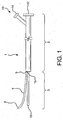
- Figure 1 shows a catheter 1 having a proximal portion 2, a distal portion 3, and a guidewire channel 4.
- the guidewire channel has a distal end 6 and a proximal end 5.
- the proximal end 5 is attached to the distal end 3 of the catheter at 15.
- Catheter 1 can include an optional guidewire lumen extending from the distal tip 10 to the proximal end 12 of the catheter assembly.
- the catheter assembly can further include proximal hub assembly 13.
- the catheter further includes an expandable prosthesis loaded on the distal portion thereof.
- the expandable prosthesis comprises a first open end and a second open end, a wall extending from the first open end to the second open end, and at least one side opening in the wall.
- the expandable prosthesis is self-expanding.
- a self-expanding prosthesis will comprise at least one shape memory material, such as nitinol.
- the expandable prosthesis can comprise a stent or stent graft.
- Suitable stent materials include, in addition to nitinol, for example, metallic, polymeric or natural materials and can comprise conventional medical grade materials such as nylon, polyacrylamide, polycarbonate, polyethylene, polyformaldehyde, polymethylmethacrylate, polypropylene, polytetrafluoroethylene, polytrifluorochlorethylene, polyvinylchloride, polyurethane, elastomeric organosilicon polymers; metals such as stainless steels, cobalt-chromium alloys and nitinol and biologically derived materials such as bovine arteries/veins, pericardium and collagen.
- conventional medical grade materials such as nylon, polyacrylamide, polycarbonate, polyethylene, polyformaldehyde, polymethylmethacrylate, polypropylene, polytetrafluoroethylene, polytrifluorochlorethylene, polyvinylchloride, polyurethane, elastomeric organosilicon polymers
- metals such as stainless steels, cobal
- Stents can also comprise bioresorbable materials such as poly(amino acids), poly(anhydrides), poly(caprolactones), poly(lactic/glycolic acid) polymers, poly(hydroxybutyrates) and poly(orthoesters).
- bioresorbable materials such as poly(amino acids), poly(anhydrides), poly(caprolactones), poly(lactic/glycolic acid) polymers, poly(hydroxybutyrates) and poly(orthoesters).
- the expandable prosthesis can comprise a stent at either the first open end, the second open end, or at both the first open end and the second open end. Moreover, the stent can be a single stent extending from the first open end to the second open end. Graft material may be used to form the wall and extends from the first open end to the second open end of the expandable prosthesis. Grafts can have various configurations and can be fabricated, for example, from tubes, sheets or films formed into tubular shapes, woven or knitted fibers or ribbons or combinations thereof. Graft materials can include conventional medical grade materials such as nylon, polyester, polyethylene, polypropylene, polytetrafluoroethylene, polyurethane and elastomeric organosilicon polymers.
- Stents can be used alone or in combination with graft materials. Stents can be configured on the external or internal surface of a graft or may be incorporated into the internal wall structure of a graft.
- Figure 2 is a side view of a catheter assembly 1 having a proximal catheter portion 2 and a proximal hub assembly 13. Loaded on the distal catheter portion is an expandable stent (or stent graft) 8. The expandable stent 8 is shown in a compressed state, maintained by a constraining sleeve 7. Also shown is distal end 6 of the guidewire channel extending out of a side opening in the stent 8, and proximal end 5 of the guidewire channel extending from the proximal end of stent 8 and being attached to the distal end of the catheter at 15.
- Figure 3 is a flow chart depicting the assembly and delivery sequence of a catheter having a guidewire channel.
- Step 1) PLACE EXPANDED MAIN-BODY DEVICE ONTO FIRST TEMPORARY TUBE.
- FIG. 4 Shown in Figure 4 is an expanded main body stent graft 40 having a side wall opening 42 and an internal side branch support 44.
- a first temporary tube 37 can be inserted through the stent graft main body lumen.
- a first stiffening mandrel 39 can be positioned within the first temporary tube.
- the stent graft can be fabricated according to the methods and materials as generally disclosed in US Patent Nos. 6,042,605 , 6,361,637 , and 6,520,986 , all to Martin et al. Details relating to the fabrication and materials used for an internal side branch support tube can be found in US Patent No. 6,645,242, to Quinn .
- Step 2) PLACE SECOND TEMPORARY TUBE THROUGH SIDE BRANCH SUPPORT.
- a second temporary tube 41 can be routed through the side wall opening 42 and through the internal side branch support 44.
- Step 3 COMPRESS MAIN BODY, ADD CONSTRAINING SHEATH
- the main body stent (40, Fig. 4 ) can be compressed and held in the compressed state by a constraining sheath 7.
- the sheath can be laced together by a deployment cord 46.
- the sheath lacing forms a generally longitudinal seam along the constraining sheath.
- the constraining sheath can be provided with a slit 43 that is oriented perpendicular to the longitudinal seam formed by deployment cord 46. The slit will subsequently provide an exit point for the second temporary tube 41. Details relating to constraining sheath materials, sheath methods of manufacture and main body compression techniques can be found, for example, in US Patent No. 6,352,561 to Leopold et al. , and US Patent No. 6,551,350 Thornton et al.
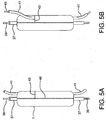
- Step 4) ROUTE DISTAL END OF SECOND TEMPORARY TUBE THROUGH SLIT IN CONSTRAINING SHEATH.
- the second temporary tube 41 can be routed through the slit 43.
- a small spring puller or hook can be inserted through the slit and be used to engage the lumen of the second temporary tube. Once the lumen is engaged the second tube can be pulled through the slit as shown in Figure 5B .
- a second stiffening mandrel 49 can be inserted through the second temporary tube.
- Step 5 REMOVE FIRST AND SECOND TEMPORARY TUBES, LEAVING BOTH STIFFENING MANDRELS IN PLACE.
- the two temporary tubes 37 and 41 can be removed, leaving the two stiffening mandrels 39 and 49 in place.
- Step 6 PUSH MAIN BODY GUIDEWIRE LUMEN AND ATTACHED GUIDEWIRE CHANNEL OVER MANDRELS.
- a catheter 1 can be provided having a proximal portion 2 and a distal portion 3.
- a hub assembly 13 can be attached to the proximal catheter portion 2.
- the hub assembly 13 has a main guidewire lumen extending from the proximal end 12, through the hub assembly, to the distal end 10 of the catheter 1.
- a deployment cord lumen 14 Also shown is a deployment cord lumen 14.
- the distal catheter portion 3 is shown having a guidewire channel 4 that is attached to the catheter at the juncture 15.
- the distal portion of the guidewire lumen can be placed onto the first stiffening mandrel 39 while the attached guidewire channel 4 is simultaneously placed onto the second stiffening mandrel 49.
- the catheter assembly can then be fully advanced so that the guidewire lumen and the attached guidewire channel 4 are driven through the compressed device.
- Step 7) BOND DISTAL TIP ONTO DISTAL CATHETER PORTION AND REMOVE MANDRELS.
- a compliant tip 16 can then be molded onto the distal end of catheter 1, as shown in Figure 2 .
- the distal end 6 of the guidewire channel 4 can then be trimmed to length.
- the catheter and hub can comprise conventional medical grade materials such as nylon, polyacrylamide, polycarbonate, polyethylene, polyformaldehyde, polymethylmethacrylate, polypropylene, polytetrafluoroethylene, polytrifluorochlorethylene, polyvinylchloride, polyurethane, elastomeric organosilicon polymers, Pebax® polyether block amide, and metals such as stainless steels and nitinol.
- conventional medical grade materials such as nylon, polyacrylamide, polycarbonate, polyethylene, polyformaldehyde, polymethylmethacrylate, polypropylene, polytetrafluoroethylene, polytrifluorochlorethylene, polyvinylchloride, polyurethane, elastomeric organosilicon polymers, Pebax® polyether block amide, and metals such as stainless steels and nitinol.
- the proximal and distal catheter portions can have diameters and lengths suitable for the delivery of a variety of stent configurations.
- Catheter diameters can range from 1 mm to over 20 mm, with a preferred range of 2 mm to 15 mm, with a most preferred range of 2 mm to 6 mm.
- Catheter lengths can vary from 20 cm to over 100 cm.
- Lengths of distal catheter portions can vary from 5 cm to over 20 cm.
- Materials useful as catheter and hub materials are also useful for fabricating the guidewire channel.
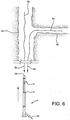
- the device can then be delivered and implanted according to the following procedure.
- two guidewires can be placed into native vessels. Shown are a main body guidewire 50 placed into a main vessel 52 and a side branch guidewire 54 placed into a side branch vessel 56.
- An introducer sheath (not shown) can be used during the guidewire placement.
- a hemostatic valve (not shown) is typically used to control back-bleeding during the guidewire and subsequent device placement.
- Typical guidewires (with 0.035" and 0.014" diameters; i.e. 0.889 mm and 0.356 mm diameters, respectively) can be used.
- Step 9) BACKLOAD GUIDEWIRE CHANNEL and MAIN BODY DEVICE ONTO TWO GUIDEWIRES.
- the catheter assembly 1 can be back loaded onto the two guidewires.
- the main body guidewire 50 is threaded into the catheter main guidewire lumen at distal tip 36, while the side branch guidewire 54 is threaded into the guidewire channel 4.
- the guidewires are fully inserted through the catheter main body lumen and through the guidewire channel, as depicted in Figure 7 .
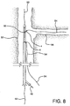
- Step 10 ADVANCE COMPRESSED DEVICE TO TARGET SITE
- the catheter assembly can now be advanced to the target site. As shown in Figure 8 the catheter and compressed main body device are advanced along the two guidewires 50, 54 until the sheath aperture 60 is aligned to the side branch vessel 56.
- the deployment cord 46 is pulled in the direction shown by arrow 62.
- the constraining sheath is split allowing the main body device 40 to self-expand and engage the main vessel 52.
- Guidewire 54 will be released from guidewire channel 4 upon expansion of device 40.
- the constraining sheath (not shown) can be left in-vivo since the sheath will be captured between the main body stent and the main vessel lumen.
- the side branch guidewire remains routed through the main body side wall opening 42, through the internal side branch support 44 and out through the proximal end of the main body device.
- the catheter 1 can now be removed, leaving the expanded main body device 40 and the side branch guidewire 54 in place.
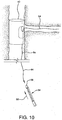
- Step 13 BACKLOAD SIDE BRANCH DEVICE ONTO SIDE BRANCH GUIDEWIRE.
- a compressed side branch stent graft can then be back loaded onto the side branch guidewire.
- the side branch guidewire 54 can be inserted into a side branch guidewire lumen at the distal tip 66 of device 64.
- the compressed side branch device 64 can then be advanced in the direction indicated by arrow 68.
- the compressed side branch device can be a stent or stent graft and can be constructed similar to the main body device 40, discussed above.
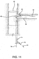
- Step 14 ADVANCE COMPRESSED SIDE BRANCH DEVICE THROUGH INTERNAL SIDE BRANCH SUPPORT CHANNEL
- the compressed side branch device 64 can be fully advanced along guidewire 54 so that the compressed device exits the main body side wall opening 42 and enters the side branch vessel 56.
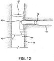
- the side branch constraining sheath can be released by pulling on the deployment cord 70 along the direction indicated by arrow 72. As shown in Figure 12 , the release of the constraining sheath allows the side branch device 76 to self-expand and engage the side branch vessel 56, the main body side wall opening 42 and the internal side-branch support channel 44.
- the side branch catheter can be removed after the side branch device is fully expanded.
- the constraining sheath (not shown) can be left in-vivo since the sheath will be captured in a fashion similar to that of the previous main body device.
- the catheter can be used to deliver an expandable stent graft and expandable side branch device to, for example, the aortic arch branches (arteries of the head, arms, and hands), lower branches of the aorta (celiac), renals, mesenterics, iliacs, the femoral, and lower extremities (legs, feet).
- aortic arch branches arteries of the head, arms, and hands
- lower branches of the aorta celiac
- renals mesenterics
- iliacs iliacs
- femoral femoral
- lower extremities legs, feet
- a catheter having an attached guidewire channel can be fabricated as follows:
Landscapes
- Health & Medical Sciences (AREA)
- Engineering & Computer Science (AREA)
- Biomedical Technology (AREA)
- Cardiology (AREA)
- Oral & Maxillofacial Surgery (AREA)
- Transplantation (AREA)
- Heart & Thoracic Surgery (AREA)
- Vascular Medicine (AREA)
- Life Sciences & Earth Sciences (AREA)
- Animal Behavior & Ethology (AREA)
- General Health & Medical Sciences (AREA)
- Public Health (AREA)
- Veterinary Medicine (AREA)
- Gastroenterology & Hepatology (AREA)
- Pulmonology (AREA)
- Media Introduction/Drainage Providing Device (AREA)
- Prostheses (AREA)
Priority Applications (1)
| Application Number | Priority Date | Filing Date | Title |
|---|---|---|---|
| EP16153699.0A EP3037062A1 (en) | 2007-04-24 | 2008-04-08 | Catheter having a guidewire channel |
Applications Claiming Priority (2)
| Application Number | Priority Date | Filing Date | Title |
|---|---|---|---|
| US11/739,169 US9358142B2 (en) | 2007-04-24 | 2007-04-24 | Catheter having guidewire channel |
| PCT/US2008/004555 WO2008130503A2 (en) | 2007-04-24 | 2008-04-08 | Catheter having guidewire channel |
Related Child Applications (2)
| Application Number | Title | Priority Date | Filing Date |
|---|---|---|---|
| EP16153699.0A Division-Into EP3037062A1 (en) | 2007-04-24 | 2008-04-08 | Catheter having a guidewire channel |
| EP16153699.0A Division EP3037062A1 (en) | 2007-04-24 | 2008-04-08 | Catheter having a guidewire channel |
Publications (2)
| Publication Number | Publication Date |
|---|---|
| EP2139436A2 EP2139436A2 (en) | 2010-01-06 |
| EP2139436B1 true EP2139436B1 (en) | 2016-04-06 |
Family
ID=39776355
Family Applications (2)
| Application Number | Title | Priority Date | Filing Date |
|---|---|---|---|
| EP08779580.3A Active EP2139436B1 (en) | 2007-04-24 | 2008-04-08 | Method of assembling a catheter having guidewire channel |
| EP16153699.0A Withdrawn EP3037062A1 (en) | 2007-04-24 | 2008-04-08 | Catheter having a guidewire channel |
Family Applications After (1)
| Application Number | Title | Priority Date | Filing Date |
|---|---|---|---|
| EP16153699.0A Withdrawn EP3037062A1 (en) | 2007-04-24 | 2008-04-08 | Catheter having a guidewire channel |
Country Status (7)
| Country | Link |
|---|---|
| US (1) | US9358142B2 (enExample) |
| EP (2) | EP2139436B1 (enExample) |
| JP (1) | JP5123376B2 (enExample) |
| AU (1) | AU2008241571B2 (enExample) |
| CA (1) | CA2683011C (enExample) |
| ES (1) | ES2581215T3 (enExample) |
| WO (1) | WO2008130503A2 (enExample) |
Families Citing this family (42)
| Publication number | Priority date | Publication date | Assignee | Title |
|---|---|---|---|---|
| US8221494B2 (en) | 2008-02-22 | 2012-07-17 | Endologix, Inc. | Apparatus and method of placement of a graft or graft system |
| US8236040B2 (en) | 2008-04-11 | 2012-08-07 | Endologix, Inc. | Bifurcated graft deployment systems and methods |
| JP5134729B2 (ja) | 2008-07-01 | 2013-01-30 | エンドロジックス、インク | カテーテルシステム |
| US8979917B2 (en) | 2008-09-25 | 2015-03-17 | Advanced Bifurcation Systems, Inc. | System and methods for treating a bifurcation |
| US12324756B2 (en) | 2008-09-25 | 2025-06-10 | Advanced Bifurcation Systems Inc. | System and methods for treating a bifurcation |
| US11298252B2 (en) | 2008-09-25 | 2022-04-12 | Advanced Bifurcation Systems Inc. | Stent alignment during treatment of a bifurcation |
| US12076258B2 (en) | 2008-09-25 | 2024-09-03 | Advanced Bifurcation Systems Inc. | Selective stent crimping |
| CA2739007C (en) | 2008-09-25 | 2017-10-31 | Advanced Bifurcation Systems Inc. | Partially crimped stent |
| US8769796B2 (en) | 2008-09-25 | 2014-07-08 | Advanced Bifurcation Systems, Inc. | Selective stent crimping |
| WO2010127040A1 (en) | 2009-04-28 | 2010-11-04 | Endologix, Inc. | Apparatus and method of placement of a graft or graft system |
| US8474120B2 (en) | 2009-10-09 | 2013-07-02 | W. L. Gore & Associates, Inc. | Bifurcated highly conformable medical device branch access |
| WO2011119882A1 (en) | 2010-03-24 | 2011-09-29 | Advanced Bifurcation Systems, Inc | Methods and systems for treating a bifurcation with provisional side branch stenting |
| CN103068345B (zh) | 2010-03-24 | 2015-10-14 | 高级分支系统股份有限公司 | 在对分叉部进行处理过程中的支架对准 |
| EP2635241B1 (en) | 2010-11-02 | 2019-02-20 | Endologix, Inc. | Apparatus for placement of a graft or graft system |
| EP4424283A3 (en) | 2011-02-08 | 2024-12-25 | Advanced Bifurcation Systems Inc. | System and methods for treating a bifurcation with a fully crimped stent |
| CA2826760A1 (en) | 2011-02-08 | 2012-08-16 | Advanced Bifurcation Systems, Inc. | Multi-stent and multi-balloon apparatus for treating bifurcations and methods of use |
| US8808350B2 (en) | 2011-03-01 | 2014-08-19 | Endologix, Inc. | Catheter system and methods of using same |
| US20120271410A1 (en) * | 2011-04-19 | 2012-10-25 | Myles Douglas | Branch endograft delivery |
| US9314328B2 (en) | 2011-08-16 | 2016-04-19 | W. L. Gore & Associates, Inc. | Branched stent graft device and deployment |
| CN104066401B (zh) | 2011-11-16 | 2016-11-09 | 波顿医疗公司 | 用于主动脉分支血管的修复的装置和方法 |
| US20140135786A1 (en) * | 2012-11-09 | 2014-05-15 | Naris Llc | Medical procedure access kit |
| US9662232B2 (en) | 2014-04-11 | 2017-05-30 | Red Vascular Technologies, LLC | Alignment system for multiple branch endografts |
| EP3139860B1 (en) | 2015-06-30 | 2024-06-12 | Endologix LLC | Locking assembly for coupling guidewire to delivery system |
| US10512533B1 (en) | 2016-02-23 | 2019-12-24 | W. L. Gore & Associates, Inc. | Branched graft assembly method in vivo |
| EP3903732B1 (en) | 2016-06-13 | 2025-07-30 | Bolton Medical, Inc. | Devices for reinforcing fenestrations in prosthetic implants |
| CN120078551A (zh) | 2016-08-02 | 2025-06-03 | 波尔顿医疗公司 | 用于将假体植入物联接到开窗体的系统、装置和方法 |
| JP6761109B2 (ja) | 2016-08-05 | 2020-09-23 | ダブリュ.エル.ゴア アンド アソシエイツ,インコーポレイティドW.L. Gore & Associates, Incorporated | 一体型医療デバイス拘束ルーメン |
| ES3013331T3 (en) | 2016-09-15 | 2025-04-11 | Gore & Ass | Staged deployment of expandable implant |
| WO2018156852A1 (en) * | 2017-02-24 | 2018-08-30 | Bolton Medical, Inc. | Stent graft delivery system with constricted sheath and method of use |
| WO2018156854A1 (en) | 2017-02-24 | 2018-08-30 | Bolton Medical, Inc. | Radially adjustable stent graft delivery system |
| EP3932373B1 (en) | 2017-02-24 | 2022-12-21 | Bolton Medical, Inc. | Delivery system for radially constricting a stent graft |
| WO2018156848A1 (en) | 2017-02-24 | 2018-08-30 | Bolton Medical, Inc. | Vascular prosthesis with crimped adapter and methods of use |
| WO2018156849A1 (en) | 2017-02-24 | 2018-08-30 | Bolton Medical, Inc. | Vascular prosthesis with fenestration ring and methods of use |
| WO2018156847A1 (en) | 2017-02-24 | 2018-08-30 | Bolton Medical, Inc. | Delivery system and method to radially constrict a stent graft |
| JP7479844B2 (ja) | 2017-02-24 | 2024-05-09 | ボルトン メディカル インコーポレイテッド | 束縛可能なステントグラフト、送達システムおよび使用方法 |
| ES2863978T3 (es) | 2017-02-24 | 2021-10-13 | Bolton Medical Inc | Sistema para constreñir radialmente un injerto de stent |
| WO2018156850A1 (en) | 2017-02-24 | 2018-08-30 | Bolton Medical, Inc. | Stent graft with fenestration lock |
| WO2018156851A1 (en) | 2017-02-24 | 2018-08-30 | Bolton Medical, Inc. | Vascular prosthesis with moveable fenestration |
| WO2019060816A2 (en) | 2017-09-25 | 2019-03-28 | Aortica Corporation | SYSTEMS, DEVICES AND METHODS FOR COUPLING PROSTHETIC IMPLANT TO A FENCED BODY |
| ES3033002T3 (en) | 2017-10-31 | 2025-07-29 | Bolton Medical Inc | Distal torque component, delivery system |
| EP3488817A1 (en) * | 2017-11-28 | 2019-05-29 | Swiss Capital - Engineering AG | A stent-graft prosthesis and system for improved delivery of a stent-graft prosthesis |
| JP7326336B2 (ja) | 2018-05-02 | 2023-08-15 | ダブリュ.エル.ゴア アンド アソシエイツ,インコーポレイティド | インプラント可能なデバイスのための拡張部材 |
Citations (4)
| Publication number | Priority date | Publication date | Assignee | Title |
|---|---|---|---|---|
| US20030055483A1 (en) * | 2001-08-23 | 2003-03-20 | Gumm Darrell C. | Rotating stent delivery system for side branch access and protection and method of using same |
| EP1512380A1 (en) * | 1999-06-04 | 2005-03-09 | Advanced Stent Technologies, Inc. | Stent delivery system for branched vessel |
| WO2005025458A1 (en) * | 2003-09-08 | 2005-03-24 | Boston Scientific Limited | Rotating expandable balloon and sheath for stent delivery to bifurcated vessel |
| WO2005084130A2 (en) * | 2004-03-04 | 2005-09-15 | Y Med Inc. | Stent delivery devices |
Family Cites Families (31)
| Publication number | Priority date | Publication date | Assignee | Title |
|---|---|---|---|---|
| FR2688401B1 (fr) * | 1992-03-12 | 1998-02-27 | Thierry Richard | Endoprothese expansible pour organe tubulaire humain ou animal, et outil de mise en place. |
| US6042605A (en) | 1995-12-14 | 2000-03-28 | Gore Enterprose Holdings, Inc. | Kink resistant stent-graft |
| EP1723931B1 (en) * | 1996-11-04 | 2012-01-04 | Advanced Stent Technologies, Inc. | Extendible stent apparatus and method for deploying the same |
| US6551350B1 (en) | 1996-12-23 | 2003-04-22 | Gore Enterprise Holdings, Inc. | Kink resistant bifurcated prosthesis |
| US6352561B1 (en) * | 1996-12-23 | 2002-03-05 | W. L. Gore & Associates | Implant deployment apparatus |
| EP0891751A1 (en) * | 1997-07-18 | 1999-01-20 | Thomas Prof. Dr. Ischinger | Vascular stent for bifurcations, sidebranches and ostial lesions and an application catheter and method for implantation |
| US6165195A (en) * | 1997-08-13 | 2000-12-26 | Advanced Cardiovascylar Systems, Inc. | Stent and catheter assembly and method for treating bifurcations |
| US6361544B1 (en) | 1997-08-13 | 2002-03-26 | Advanced Cardiovascular Systems, Inc. | Stent and catheter assembly and method for treating bifurcations |
| US6520988B1 (en) * | 1997-09-24 | 2003-02-18 | Medtronic Ave, Inc. | Endolumenal prosthesis and method of use in bifurcation regions of body lumens |
| WO1999034749A1 (en) | 1998-01-08 | 1999-07-15 | Mark Wilson Ian Webster | Self-expanding bifurcation stent and delivery system |
| US7387639B2 (en) * | 1999-06-04 | 2008-06-17 | Advanced Stent Technologies, Inc. | Short sleeve stent delivery catheter and methods |
| US6908477B2 (en) * | 2000-10-13 | 2005-06-21 | Rex Medical, L.P. | Methods of implanting covered stents with side branch |
| US6645242B1 (en) * | 2000-12-11 | 2003-11-11 | Stephen F. Quinn | Bifurcated side-access intravascular stent graft |
| US8617231B2 (en) | 2001-05-18 | 2013-12-31 | Boston Scientific Scimed, Inc. | Dual guidewire exchange catheter system |
| EP1551333A4 (en) * | 2002-06-13 | 2010-01-06 | Existent Inc | GUIDE WIRE SYSTEM |
| US6994721B2 (en) * | 2002-10-21 | 2006-02-07 | Israel Henry M | Stent assembly |
| US20040102719A1 (en) | 2002-11-22 | 2004-05-27 | Velocimed, L.L.C. | Guide wire control catheters for crossing occlusions and related methods of use |
| US20040133130A1 (en) | 2003-01-06 | 2004-07-08 | Ferry Steven J. | Magnetically navigable medical guidewire |
| US20040143286A1 (en) * | 2003-01-17 | 2004-07-22 | Johnson Eric G. | Catheter with disruptable guidewire channel |
| US20040199073A1 (en) | 2003-04-03 | 2004-10-07 | Agency For Science, Technology And Research | Method and apparatus for measuring motion of a body in a number of dimensions |
| WO2004089249A1 (en) | 2003-04-03 | 2004-10-21 | William A. Cook Australia Pty. Ltd. | Branch stent graft deployment and method |
| US8784472B2 (en) * | 2003-08-15 | 2014-07-22 | Boston Scientific Scimed, Inc. | Clutch driven stent delivery system |
| US20050049662A1 (en) | 2003-08-27 | 2005-03-03 | Kimberly-Clark Worldwide, Inc. | Adjustable temperature heat patch |
| US7641684B2 (en) * | 2003-10-16 | 2010-01-05 | Minvasys, Sa | Catheter system for stenting bifurcated vessels |
| US7744619B2 (en) | 2004-02-24 | 2010-06-29 | Boston Scientific Scimed, Inc. | Rotatable catheter assembly |
| US20060041303A1 (en) | 2004-08-18 | 2006-02-23 | Israel Henry M | Guidewire with stopper |
| US7635383B2 (en) * | 2004-09-28 | 2009-12-22 | Boston Scientific Scimed, Inc. | Rotating stent delivery system for side branch access and protection and method of using same |
| US8562566B2 (en) * | 2005-02-28 | 2013-10-22 | Boston Scientific Scimed, Inc. | Stent delivery and guidewire guidance system |
| US7485140B2 (en) | 2005-06-17 | 2009-02-03 | Boston Scientific Scimed, Inc. | Bifurcation stent assembly |
| US20070083215A1 (en) | 2005-10-07 | 2007-04-12 | Hamer Rochelle M | Conduit for interventional procedures |
| US20070106245A1 (en) | 2005-11-08 | 2007-05-10 | Kerberos Proximal Solutions, Inc. | Infusion guidewire |
-
2007
- 2007-04-24 US US11/739,169 patent/US9358142B2/en active Active
-
2008
- 2008-04-08 JP JP2010506197A patent/JP5123376B2/ja active Active
- 2008-04-08 EP EP08779580.3A patent/EP2139436B1/en active Active
- 2008-04-08 ES ES08779580.3T patent/ES2581215T3/es active Active
- 2008-04-08 WO PCT/US2008/004555 patent/WO2008130503A2/en not_active Ceased
- 2008-04-08 CA CA2683011A patent/CA2683011C/en active Active
- 2008-04-08 EP EP16153699.0A patent/EP3037062A1/en not_active Withdrawn
- 2008-04-08 AU AU2008241571A patent/AU2008241571B2/en active Active
Patent Citations (4)
| Publication number | Priority date | Publication date | Assignee | Title |
|---|---|---|---|---|
| EP1512380A1 (en) * | 1999-06-04 | 2005-03-09 | Advanced Stent Technologies, Inc. | Stent delivery system for branched vessel |
| US20030055483A1 (en) * | 2001-08-23 | 2003-03-20 | Gumm Darrell C. | Rotating stent delivery system for side branch access and protection and method of using same |
| WO2005025458A1 (en) * | 2003-09-08 | 2005-03-24 | Boston Scientific Limited | Rotating expandable balloon and sheath for stent delivery to bifurcated vessel |
| WO2005084130A2 (en) * | 2004-03-04 | 2005-09-15 | Y Med Inc. | Stent delivery devices |
Also Published As
| Publication number | Publication date |
|---|---|
| CA2683011A1 (en) | 2008-10-30 |
| JP5123376B2 (ja) | 2013-01-23 |
| EP2139436A2 (en) | 2010-01-06 |
| US20080269867A1 (en) | 2008-10-30 |
| AU2008241571B2 (en) | 2012-05-03 |
| ES2581215T3 (es) | 2016-09-02 |
| US9358142B2 (en) | 2016-06-07 |
| EP3037062A1 (en) | 2016-06-29 |
| CA2683011C (en) | 2013-01-15 |
| WO2008130503A2 (en) | 2008-10-30 |
| JP2010524630A (ja) | 2010-07-22 |
| AU2008241571A1 (en) | 2008-10-30 |
| WO2008130503A3 (en) | 2008-12-31 |
Similar Documents
| Publication | Publication Date | Title |
|---|---|---|
| EP2139436B1 (en) | Method of assembling a catheter having guidewire channel | |
| AU2008244607B2 (en) | Side branched endoluminal prostheses and methods of delivery thereof | |
| US7717950B2 (en) | Double sheath deployment system | |
| US12403023B2 (en) | Delivery system aid and associated systems and methods | |
| EP3245986B1 (en) | Wire retention and release mechanisms | |
| HK1224914A1 (en) | Catheter having a guidewire channel | |
| HK1164102A (en) | Side branched endoluminal prostheses | |
| HK1164102B (en) | Side branched endoluminal prostheses |
Legal Events
| Date | Code | Title | Description |
|---|---|---|---|
| PUAI | Public reference made under article 153(3) epc to a published international application that has entered the european phase |
Free format text: ORIGINAL CODE: 0009012 |
|
| 17P | Request for examination filed |
Effective date: 20091019 |
|
| AK | Designated contracting states |
Kind code of ref document: A2 Designated state(s): AT BE BG CH CY CZ DE DK EE ES FI FR GB GR HR HU IE IS IT LI LT LU LV MC MT NL NO PL PT RO SE SI SK TR |
|
| 17Q | First examination report despatched |
Effective date: 20101215 |
|
| DAX | Request for extension of the european patent (deleted) | ||
| RAP1 | Party data changed (applicant data changed or rights of an application transferred) |
Owner name: W.L. GORE & ASSOCIATES, INC. |
|
| REG | Reference to a national code |
Ref country code: DE Ref legal event code: R079 Ref document number: 602008043347 Country of ref document: DE Free format text: PREVIOUS MAIN CLASS: A61F0002840000 Ipc: A61F0002970000 |
|
| RIC1 | Information provided on ipc code assigned before grant |
Ipc: A61F 2/82 20130101ALI20151029BHEP Ipc: A61F 2/97 20130101AFI20151029BHEP Ipc: A61F 2/06 20130101ALI20151029BHEP Ipc: A61F 2/954 20130101ALI20151029BHEP Ipc: A61F 2/07 20130101ALI20151029BHEP Ipc: A61F 2/856 20130101ALI20151029BHEP |
|
| GRAP | Despatch of communication of intention to grant a patent |
Free format text: ORIGINAL CODE: EPIDOSNIGR1 |
|
| INTG | Intention to grant announced |
Effective date: 20151209 |
|
| GRAS | Grant fee paid |
Free format text: ORIGINAL CODE: EPIDOSNIGR3 |
|
| GRAA | (expected) grant |
Free format text: ORIGINAL CODE: 0009210 |
|
| RIN1 | Information on inventor provided before grant (corrected) |
Inventor name: JOHNSON, ERIC GERARD |
|
| AK | Designated contracting states |
Kind code of ref document: B1 Designated state(s): AT BE BG CH CY CZ DE DK EE ES FI FR GB GR HR HU IE IS IT LI LT LU LV MC MT NL NO PL PT RO SE SI SK TR |
|
| REG | Reference to a national code |
Ref country code: GB Ref legal event code: FG4D |
|
| REG | Reference to a national code |
Ref country code: AT Ref legal event code: REF Ref document number: 786903 Country of ref document: AT Kind code of ref document: T Effective date: 20160415 Ref country code: CH Ref legal event code: EP |
|
| REG | Reference to a national code |
Ref country code: IE Ref legal event code: FG4D |
|
| REG | Reference to a national code |
Ref country code: DE Ref legal event code: R096 Ref document number: 602008043347 Country of ref document: DE |
|
| REG | Reference to a national code |
Ref country code: FR Ref legal event code: PLFP Year of fee payment: 9 |
|
| REG | Reference to a national code |
Ref country code: LT Ref legal event code: MG4D Ref country code: NL Ref legal event code: MP Effective date: 20160406 |
|
| REG | Reference to a national code |
Ref country code: AT Ref legal event code: MK05 Ref document number: 786903 Country of ref document: AT Kind code of ref document: T Effective date: 20160406 |
|
| PG25 | Lapsed in a contracting state [announced via postgrant information from national office to epo] |
Ref country code: BE Free format text: LAPSE BECAUSE OF NON-PAYMENT OF DUE FEES Effective date: 20160430 |
|
| REG | Reference to a national code |
Ref country code: ES Ref legal event code: FG2A Ref document number: 2581215 Country of ref document: ES Kind code of ref document: T3 Effective date: 20160902 |
|
| PG25 | Lapsed in a contracting state [announced via postgrant information from national office to epo] |
Ref country code: NL Free format text: LAPSE BECAUSE OF FAILURE TO SUBMIT A TRANSLATION OF THE DESCRIPTION OR TO PAY THE FEE WITHIN THE PRESCRIBED TIME-LIMIT Effective date: 20160406 |
|
| PG25 | Lapsed in a contracting state [announced via postgrant information from national office to epo] |
Ref country code: IS Free format text: LAPSE BECAUSE OF FAILURE TO SUBMIT A TRANSLATION OF THE DESCRIPTION OR TO PAY THE FEE WITHIN THE PRESCRIBED TIME-LIMIT Effective date: 20160806 Ref country code: FI Free format text: LAPSE BECAUSE OF FAILURE TO SUBMIT A TRANSLATION OF THE DESCRIPTION OR TO PAY THE FEE WITHIN THE PRESCRIBED TIME-LIMIT Effective date: 20160406 Ref country code: PL Free format text: LAPSE BECAUSE OF FAILURE TO SUBMIT A TRANSLATION OF THE DESCRIPTION OR TO PAY THE FEE WITHIN THE PRESCRIBED TIME-LIMIT Effective date: 20160406 Ref country code: LT Free format text: LAPSE BECAUSE OF FAILURE TO SUBMIT A TRANSLATION OF THE DESCRIPTION OR TO PAY THE FEE WITHIN THE PRESCRIBED TIME-LIMIT Effective date: 20160406 Ref country code: NO Free format text: LAPSE BECAUSE OF FAILURE TO SUBMIT A TRANSLATION OF THE DESCRIPTION OR TO PAY THE FEE WITHIN THE PRESCRIBED TIME-LIMIT Effective date: 20160706 |
|
| PG25 | Lapsed in a contracting state [announced via postgrant information from national office to epo] |
Ref country code: HR Free format text: LAPSE BECAUSE OF FAILURE TO SUBMIT A TRANSLATION OF THE DESCRIPTION OR TO PAY THE FEE WITHIN THE PRESCRIBED TIME-LIMIT Effective date: 20160406 Ref country code: LV Free format text: LAPSE BECAUSE OF FAILURE TO SUBMIT A TRANSLATION OF THE DESCRIPTION OR TO PAY THE FEE WITHIN THE PRESCRIBED TIME-LIMIT Effective date: 20160406 Ref country code: GR Free format text: LAPSE BECAUSE OF FAILURE TO SUBMIT A TRANSLATION OF THE DESCRIPTION OR TO PAY THE FEE WITHIN THE PRESCRIBED TIME-LIMIT Effective date: 20160707 Ref country code: SE Free format text: LAPSE BECAUSE OF FAILURE TO SUBMIT A TRANSLATION OF THE DESCRIPTION OR TO PAY THE FEE WITHIN THE PRESCRIBED TIME-LIMIT Effective date: 20160406 Ref country code: PT Free format text: LAPSE BECAUSE OF FAILURE TO SUBMIT A TRANSLATION OF THE DESCRIPTION OR TO PAY THE FEE WITHIN THE PRESCRIBED TIME-LIMIT Effective date: 20160808 Ref country code: AT Free format text: LAPSE BECAUSE OF FAILURE TO SUBMIT A TRANSLATION OF THE DESCRIPTION OR TO PAY THE FEE WITHIN THE PRESCRIBED TIME-LIMIT Effective date: 20160406 |
|
| REG | Reference to a national code |
Ref country code: CH Ref legal event code: PL |
|
| PG25 | Lapsed in a contracting state [announced via postgrant information from national office to epo] |
Ref country code: BE Free format text: LAPSE BECAUSE OF FAILURE TO SUBMIT A TRANSLATION OF THE DESCRIPTION OR TO PAY THE FEE WITHIN THE PRESCRIBED TIME-LIMIT Effective date: 20160406 |
|
| REG | Reference to a national code |
Ref country code: DE Ref legal event code: R097 Ref document number: 602008043347 Country of ref document: DE |
|
| PG25 | Lapsed in a contracting state [announced via postgrant information from national office to epo] |
Ref country code: CZ Free format text: LAPSE BECAUSE OF FAILURE TO SUBMIT A TRANSLATION OF THE DESCRIPTION OR TO PAY THE FEE WITHIN THE PRESCRIBED TIME-LIMIT Effective date: 20160406 Ref country code: DK Free format text: LAPSE BECAUSE OF FAILURE TO SUBMIT A TRANSLATION OF THE DESCRIPTION OR TO PAY THE FEE WITHIN THE PRESCRIBED TIME-LIMIT Effective date: 20160406 Ref country code: LI Free format text: LAPSE BECAUSE OF NON-PAYMENT OF DUE FEES Effective date: 20160430 Ref country code: RO Free format text: LAPSE BECAUSE OF FAILURE TO SUBMIT A TRANSLATION OF THE DESCRIPTION OR TO PAY THE FEE WITHIN THE PRESCRIBED TIME-LIMIT Effective date: 20160406 Ref country code: SK Free format text: LAPSE BECAUSE OF FAILURE TO SUBMIT A TRANSLATION OF THE DESCRIPTION OR TO PAY THE FEE WITHIN THE PRESCRIBED TIME-LIMIT Effective date: 20160406 Ref country code: CH Free format text: LAPSE BECAUSE OF NON-PAYMENT OF DUE FEES Effective date: 20160430 Ref country code: MC Free format text: LAPSE BECAUSE OF FAILURE TO SUBMIT A TRANSLATION OF THE DESCRIPTION OR TO PAY THE FEE WITHIN THE PRESCRIBED TIME-LIMIT Effective date: 20160406 Ref country code: EE Free format text: LAPSE BECAUSE OF FAILURE TO SUBMIT A TRANSLATION OF THE DESCRIPTION OR TO PAY THE FEE WITHIN THE PRESCRIBED TIME-LIMIT Effective date: 20160406 |
|
| PLBE | No opposition filed within time limit |
Free format text: ORIGINAL CODE: 0009261 |
|
| STAA | Information on the status of an ep patent application or granted ep patent |
Free format text: STATUS: NO OPPOSITION FILED WITHIN TIME LIMIT |
|
| 26N | No opposition filed |
Effective date: 20170110 |
|
| REG | Reference to a national code |
Ref country code: FR Ref legal event code: PLFP Year of fee payment: 10 |
|
| PG25 | Lapsed in a contracting state [announced via postgrant information from national office to epo] |
Ref country code: SI Free format text: LAPSE BECAUSE OF FAILURE TO SUBMIT A TRANSLATION OF THE DESCRIPTION OR TO PAY THE FEE WITHIN THE PRESCRIBED TIME-LIMIT Effective date: 20160406 |
|
| REG | Reference to a national code |
Ref country code: FR Ref legal event code: PLFP Year of fee payment: 11 |
|
| PG25 | Lapsed in a contracting state [announced via postgrant information from national office to epo] |
Ref country code: CY Free format text: LAPSE BECAUSE OF FAILURE TO SUBMIT A TRANSLATION OF THE DESCRIPTION OR TO PAY THE FEE WITHIN THE PRESCRIBED TIME-LIMIT Effective date: 20160406 Ref country code: HU Free format text: LAPSE BECAUSE OF FAILURE TO SUBMIT A TRANSLATION OF THE DESCRIPTION OR TO PAY THE FEE WITHIN THE PRESCRIBED TIME-LIMIT; INVALID AB INITIO Effective date: 20080408 |
|
| PG25 | Lapsed in a contracting state [announced via postgrant information from national office to epo] |
Ref country code: MT Free format text: LAPSE BECAUSE OF NON-PAYMENT OF DUE FEES Effective date: 20160430 Ref country code: TR Free format text: LAPSE BECAUSE OF FAILURE TO SUBMIT A TRANSLATION OF THE DESCRIPTION OR TO PAY THE FEE WITHIN THE PRESCRIBED TIME-LIMIT Effective date: 20160406 Ref country code: LU Free format text: LAPSE BECAUSE OF NON-PAYMENT OF DUE FEES Effective date: 20160408 |
|
| PG25 | Lapsed in a contracting state [announced via postgrant information from national office to epo] |
Ref country code: BG Free format text: LAPSE BECAUSE OF FAILURE TO SUBMIT A TRANSLATION OF THE DESCRIPTION OR TO PAY THE FEE WITHIN THE PRESCRIBED TIME-LIMIT Effective date: 20160406 |
|
| P01 | Opt-out of the competence of the unified patent court (upc) registered |
Effective date: 20230516 |
|
| PGFP | Annual fee paid to national office [announced via postgrant information from national office to epo] |
Ref country code: IE Payment date: 20250321 Year of fee payment: 18 |
|
| PGFP | Annual fee paid to national office [announced via postgrant information from national office to epo] |
Ref country code: FR Payment date: 20250319 Year of fee payment: 18 |
|
| PGFP | Annual fee paid to national office [announced via postgrant information from national office to epo] |
Ref country code: IT Payment date: 20250319 Year of fee payment: 18 Ref country code: GB Payment date: 20250319 Year of fee payment: 18 |
|
| PGFP | Annual fee paid to national office [announced via postgrant information from national office to epo] |
Ref country code: DE Payment date: 20250319 Year of fee payment: 18 |
|
| PGFP | Annual fee paid to national office [announced via postgrant information from national office to epo] |
Ref country code: ES Payment date: 20250502 Year of fee payment: 18 |