EP2139361B1 - Electromotive furniture drive - Google Patents
Electromotive furniture drive Download PDFInfo
- Publication number
- EP2139361B1 EP2139361B1 EP07856603.1A EP07856603A EP2139361B1 EP 2139361 B1 EP2139361 B1 EP 2139361B1 EP 07856603 A EP07856603 A EP 07856603A EP 2139361 B1 EP2139361 B1 EP 2139361B1
- Authority
- EP
- European Patent Office
- Prior art keywords
- furniture
- power transmission
- transmission element
- furniture drive
- drive
- Prior art date
- Legal status (The legal status is an assumption and is not a legal conclusion. Google has not performed a legal analysis and makes no representation as to the accuracy of the status listed.)
- Not-in-force
Links
Images



Classifications
-
- A—HUMAN NECESSITIES
- A47—FURNITURE; DOMESTIC ARTICLES OR APPLIANCES; COFFEE MILLS; SPICE MILLS; SUCTION CLEANERS IN GENERAL
- A47B—TABLES; DESKS; OFFICE FURNITURE; CABINETS; DRAWERS; GENERAL DETAILS OF FURNITURE
- A47B88/00—Drawers for tables, cabinets or like furniture; Guides for drawers
- A47B88/40—Sliding drawers; Slides or guides therefor
- A47B88/453—Actuated drawers
- A47B88/457—Actuated drawers operated by electrically-powered actuation means
-
- E—FIXED CONSTRUCTIONS
- E05—LOCKS; KEYS; WINDOW OR DOOR FITTINGS; SAFES
- E05Y—INDEXING SCHEME ASSOCIATED WITH SUBCLASSES E05D AND E05F, RELATING TO CONSTRUCTION ELEMENTS, ELECTRIC CONTROL, POWER SUPPLY, POWER SIGNAL OR TRANSMISSION, USER INTERFACES, MOUNTING OR COUPLING, DETAILS, ACCESSORIES, AUXILIARY OPERATIONS NOT OTHERWISE PROVIDED FOR, APPLICATION THEREOF
- E05Y2201/00—Constructional elements; Accessories therefor
- E05Y2201/60—Suspension or transmission members; Accessories therefor
- E05Y2201/622—Suspension or transmission members elements
- E05Y2201/71—Toothed gearing
- E05Y2201/722—Racks
-
- F—MECHANICAL ENGINEERING; LIGHTING; HEATING; WEAPONS; BLASTING
- F16—ENGINEERING ELEMENTS AND UNITS; GENERAL MEASURES FOR PRODUCING AND MAINTAINING EFFECTIVE FUNCTIONING OF MACHINES OR INSTALLATIONS; THERMAL INSULATION IN GENERAL
- F16C—SHAFTS; FLEXIBLE SHAFTS; ELEMENTS OR CRANKSHAFT MECHANISMS; ROTARY BODIES OTHER THAN GEARING ELEMENTS; BEARINGS
- F16C1/00—Flexible shafts; Mechanical means for transmitting movement in a flexible sheathing
- F16C1/10—Means for transmitting linear movement in a flexible sheathing, e.g. "Bowden-mechanisms"
- F16C1/12—Arrangements for transmitting movement to or from the flexible member
- F16C1/18—Arrangements for transmitting movement to or from the flexible member in which the end portion of the flexible member is laid along a curved surface of a pivoted member
-
- F—MECHANICAL ENGINEERING; LIGHTING; HEATING; WEAPONS; BLASTING
- F16—ENGINEERING ELEMENTS AND UNITS; GENERAL MEASURES FOR PRODUCING AND MAINTAINING EFFECTIVE FUNCTIONING OF MACHINES OR INSTALLATIONS; THERMAL INSULATION IN GENERAL
- F16C—SHAFTS; FLEXIBLE SHAFTS; ELEMENTS OR CRANKSHAFT MECHANISMS; ROTARY BODIES OTHER THAN GEARING ELEMENTS; BEARINGS
- F16C2314/00—Personal or domestic articles, e.g. household appliances such as washing machines, dryers
- F16C2314/70—Furniture
Definitions
- the invention relates to an electromotive furniture drive referred to in the preamble of claim 1 for adjusting parts of a furniture relative to each other, in particular a drawer relative to a body of a cabinet.
- Such furniture drives are well known, for example by DE 10 17 531 , or WO2006 / 029894 ,
- AT 413 631 B is an electromotive furniture drive for adjusting parts of a furniture relative to each other, in particular a drawer relative to a cabinet of a cabinet, known which has a drive unit, the output member is in the mounting position of the furniture drive with a part to be adjusted of the furniture in power transmission connection.
- the drive unit is designed as a rack and pinion gear having a standing with an electric motor of the drive unit in rotary drive connection gear which is in engagement with a rack which forms the output element of the furniture drive and is connected to a body of a drawer such that the Drawer relative to the body of the furniture according to the direction of rotation of the gear is retractable or retractable.
- a disadvantage of the known furniture drive is that it offers little freedom in terms of its arrangement on the body of the furniture, as the Rack is attached to the drawer and the gear must be in each adjustment position of the drawer in engagement with the rack.
- the invention has for its object to provide an electromotive furniture drive referred to in the preamble of claim 1 species, which does not have the disadvantages of the known furniture drive, ie in which the freedoms are increased with respect to the arrangement of the furniture drive to the furniture.
- the basic idea of the teaching according to the invention is to provide a flexible power transmission element for the production of a power transmission connection between the output element of the drive unit and the part of the furniture to be adjusted, which however can be claimed simultaneously for tension and compression.
- the drive unit of the furniture drive can be arranged at almost any point of the furniture, wherein the power transmission connection between the output element of the drive unit and the part to be adjusted of the furniture is made via the flexible force transmission element.
- the force transmission element can be claimed both train and on pressure, both adjusting movements can be performed by means of the furniture drive according to the invention, in which the force transmission element is subjected to pressure, such as an extension of a drawer, as well as adjusting movements, in which the power transmission element to train is claimed, for example, a retraction of a drawer.
- the furniture drive according to the invention is relatively simple and inexpensive to produce and robust.
- the furniture drive according to the invention is suitable for adjusting any parts of a piece of furniture, as far as the requisite adjusting forces can be transmitted from the power transmission element.
- the furniture drive according to the invention is particularly well suited for adjusting pull-outs, in particular drawers, relative to a carcass of a cabinet. Characterized in that the force transmission element is flexible and thus can be deflected, it is inventively possible, for example, to attach the housing of the furniture drive to a rear wall of a cabinet, while one of the drawer to be adjusted facing the end of the power transmission element is fixed to the drawer.
- the furniture drive according to the invention is relatively simple and inexpensive to produce and robust in construction.
- An advantageous development of the teaching according to the invention provides that a part of the furniture to be adjusted facing the first end of the power transmission element is fixed to the part to be adjusted of the furniture.
- the first end of the power transmission element can be fastened, for example, by means of a suitable fitting on the part of the furniture to be adjusted.
- a decoupling of the drawer of the drive unit instead, with the drawer moves after decoupling due to their inertia in the direction of the retracted position. Because the drawer is in the range of the end position This movement is decoupled from the drive unit, the risk is avoided that a body part of a user is trapped under the action of the driving force of the drive unit between the drawer and the body of the furniture.
- a second end of the force transmission element remote from the part of the furniture to be adjusted can be fixed to the output element.
- the output element can be designed as a rotatably drivable winding drum on which the force transmission element can be wound up and from which the force transmission element can be unwound.
- An advantageous development of the aforementioned embodiment provides that a lying between the pressure point and the second end of the power transmission element unloaded part of the power transmission element is receivable by a receiving device.
- the unloaded part of the power transmission element is accommodated in the receiving device in an orderly manner.
- the receiving device has a drum-like receptacle in which the second end of the power transmission element spirally is hineinbewegbar.
- the force transmission element sets in an adjusting movement, in which increases the distance of the second end of the force transmission element of the Anpreßstelle, a spiral in the drum-like receptacle.
- the output element of the furniture drive according to the invention can be, for example, a linearly movable output element along a linear movement axis.
- the output element is rotationally driven by an electric motor of the drive unit, as provided by an advantageous development of the teaching of the invention. In this way, a particularly simple construction of the furniture drive according to the invention.
- a development of the aforementioned embodiment provides that the drum-like receptacle is arranged offset in the axial direction to the axis of rotation of the output element. In this way, the furniture drive according to the invention is particularly space-saving and compact.
- the drum-like receptacle is in rotary drive connection with the output element, in particular rotationally fixed or substantially non-rotatably connected to the output element.
- the output element is not rotationally driven by an electric motor of the drive unit, but via power transmission element by hand. Due in particular essentially non-rotatable connection of the drum-like receptacle with the output element in this case, the receptacle rotates substantially synchronously with. In this way, the friction between the moving into the receiving container power transmission element and the inner wall is reduced.
- the power transmission element particularly easily into the receptacle, in a spiral manner in the form of adjacent to each other in the axial direction of the receptacle turns. If the axial extent of the receptacle is filled with a layer of adjacent turns, so the force transmission element lies over this layer in one or more further layers of axially adjacent turns arranged in the receptacle a.
- the force transmission element is designed as a rack which is in engagement with a gear which forms the output element of the drive unit or is in rotary drive connection with the output element of the drive unit.
- the rack which forms the power transmission element of the furniture drive, positively engages with a toothing of the toothed wheel, which forms the output element of the drive unit or is in rotary drive connection with the output element of the drive unit. In this way, a slip between the power transmission element and the output element is avoided.
- racks are available as relatively simple and inexpensive standard components and are suitable for transmitting considerable forces.
- the rack for example Made of plastic and be dimensioned so that on the one hand flexible, but on the other hand in the required manner to train and pressure claims.
- the force transmission element is accommodated in a sheath. In this embodiment, it is avoided that the force transmission element buckles laterally under compressive stress.
- the first and the second end of the power transmission element are arranged at an angle to each other.
- Such an angular arrangement of the ends of the power transmission element to each other according to the invention allows characterized in that the force transmission element is designed to be flexible.
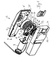
- FIG. 1 an embodiment of a furniture drive 2 according to the invention is shown, which in this embodiment for adjusting a in Fig. 1 not shown drawer of a Fig. 1 also not shown cabinet serves.
- the furniture drive 2 has a housing 5 formed by two half-shells 4, 4 'in which a drive unit 6 with an electric motor 8 is accommodated.
- the electric motor 8 has an output shaft 10, which is formed in this embodiment as a worm and is in engagement with a worm wheel 12 of a gear assembly 14.
- a first gear 16 is rotatably connected, which meshes with a second gear 18, which in turn meshes with a first toothing 20 of a third gear 22.
- the worm wheel 12 with the first gear 16, the second gear 18 and the third gear 22 are rotatably supported on a gear holder 24 which is held inside the housing 5.
- the furniture drive 2 has a flexible force transmission element that can be subjected to tension and compression, which in this exemplary embodiment is formed by a toothed rack 26.
- the rack 26 is in this embodiment to achieve the inventively provided flexibility of plastic and is dimensioned in its cross-section so that on the one hand the required flexibility is achieved, on the other hand, however, the required tensile and compressive forces can be transmitted without damaging the rack 26.
- the third gear 22 forms in this embodiment, the output element of the drive unit 6 and is provided with a first toothing 20 in the axial direction of the third gear 22 offset second toothing with which the rack 26 is engaged.
- a remote from the adjusting part of the furniture second end 32 of the rack 26 is movable relative to the third gear, so not fixed to this.
- pressing means are provided, which in this embodiment have a pressure roller 34 which press the rack 26 at a contact point 36 to the second toothing 30 of the third gear 22 and hold the rack 26 in force communication with the third gear 22.
- the second gear 18 is in engagement with the first toothing 20 and the rack 26 in engagement with the second toothing 30 of the third gear 22.
- the third gear 22 has a single toothing, with the Both the second gear 18 as also the rack 26 are engaged.
- a receiving device For receiving a lying between the pressure point 36 and the second end 32 of the rack 26 unloaded part of the rack 26, a receiving device is provided which has a drum-like receptacle 38 in this embodiment, in which the second end 32 of the rack 26 is hineinbewegbar spirally, such as this in Fig. 1 is indicated. How out Fig. 1 can be seen, the drum-like receptacle 38 is arranged offset in the axial direction of the axis of rotation of the third gear 22 to the same.
- the drum-like receptacle 38 is rotatably connected via an axis 39 with the third gear 22 so that it rotates synchronously with the third gear 22.
- an integrally formed on the gear holder 24 guide is provided.
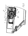
- FIG. 2 in which a perspective view of the furniture drive according to Fig. 2 is shown in FIG Fig. 1 Sheath 40, not shown, for rack 26. Sheathing 40 is fixed in position and has a lower flexibility than rack 26, with rack 26 soily received in shroud 40 and slidably reciprocated relative to shroud 40 , Out Fig. 2 It can also be seen that the second gear 18 is in engagement with the first gear 20 and the rack 26 is in engagement with the second gear 30 of the third gear 22.
- Fig. 3 shows a further perspective view of the furniture drive 2, wherein it can be seen that the pressure roller 34 presses the rack 26 at the pressure point 36 against the second toothing 30 of the third gear 22 and so holds the rack 26 in power transmission connection with the third gear 22.
- Fig. 4 shows the furniture drive 2 in mounting position on a cabinet, for reasons of illustration, parts of the cabinet, in particular its rear wall, to which the housing 5 of the furniture drive 2 is attached, are not shown.
- the furniture drive 2 is used to adjust an in Fig. 4 also not shown drawer, which is connected via movable rails 42, 44 of telescopic rail assemblies extendable to the body of the cabinet.
- Fig. 4 can be seen, in this embodiment, the ends of the rack 40 received in the rack 26 are arranged at an angle to each other, in this embodiment namely at an angle of about 90 °.
- Fig. 5 shows a detail in the region of the connection of the rack 26 with the movable telescopic rail 24.
- the first end of the rack 26 via a fitting 46 is fixedly connected to the movable rail 42.
- the pin 48 is guided in an axial slot 50 of the casing in the adjustment direction, which corresponds to the axial direction of the casing 42.
- the drawer can also be manually moved from the extended position to the retracted position by a user einschiebt the drawer by hand.
- the rack 26 is subjected to pressure, where it is the third Gear 22 so wooan administrat that this in Fig. 1 moved counterclockwise.
- the second end 32 of the rack 26 moves into the drum-like receptacle 38 and abuts in the form of successive turns in the axial direction of the receptacle 38 to the cylindrical inner wall of the receptacle 38.
- the receptacle 38 Since the receptacle 38 is rotatably connected via the axis 39 with the third gear 22, in this case the friction between the second end 32 of the rack 26 and the inner wall of the receptacle 38 is substantially reduced. In this way, it is possible that the rack 38 arranged in the form of arranged in the axial direction of the receptacle 38 juxtaposed turns to the cylindrical inner wall of the receptacle 38. Characterized in that the rack 26 has certain elastic properties, it puts itself when moving into the receptacle 38 close to the inner wall.
- the rack 26 subsequently sets in a second layer of axially juxtaposed turns in the receptacle 38 a. If necessary, this process repeats to form additional layers until the drawer is in its retracted position again. It has surprisingly been found that the co-rotation of the receptacle 38 upon rotation of the third gear 22, the orderly recording of the rack 26 is substantially promoted in the receptacle 38.
- the furniture drive 2 according to the invention is relatively simple and inexpensive to produce and offers in terms of the arrangement of the furniture drive 2 at one Body of furniture greater liberties than known furniture drives. How out Fig. 4 it can be seen, the furniture drive in the illustrated embodiment is attached to a (not shown) rear wall of the cabinet, wherein the ends of the rack 26 are arranged at an angle to each other and in this embodiment form an angle of about 90 ° with each other.
Landscapes
- Drawers Of Furniture (AREA)
- Transmission Devices (AREA)
Description
Die Erfindung betrifft einen elektromotorischen Möbelantrieb der im Oberbegriff des Anspruchs 1 genannten Art zum Verstellen von Teilen eines Möbels relativ zueinander, insbesondere einer Schublade relativ zu einem Korpus eines Schrankes.The invention relates to an electromotive furniture drive referred to in the preamble of
Derartige Möbelantriebe sind allgemein bekannt, beispielsweise durch
Durch
Ein Nachteil des bekannten Möbelantriebs besteht darin, daß er hinsichtlich seiner Anordnung an dem Korpus des Möbels nur geringe Freiheiten bietet, da die Zahnstange an der Schublade befestigt ist und sich das Zahnrad in jeder Verstellposition der Schublade in Eingriff mit der Zahnstange befinden muß.A disadvantage of the known furniture drive is that it offers little freedom in terms of its arrangement on the body of the furniture, as the Rack is attached to the drawer and the gear must be in each adjustment position of the drawer in engagement with the rack.
Der Erfindung liegt die Aufgabe zugrunde, einen elektromotorischen Möbelantrieb der im Oberbegriff des Anspruchs 1 genannten Art anzugeben, der die Nachteile des bekannten Möbelantriebs nicht aufweist, bei dem also die Freiheiten hinsichtlich der Anordnung des Möbelantriebs an dem Möbel erhöht sind.The invention has for its object to provide an electromotive furniture drive referred to in the preamble of
Diese Aufgabe wird durch die im Anspruch 1 angegebene Lehre gelöst.This object is achieved by the teaching defined in
Der Grundgedanke der erfindungsgemäßen Lehre besteht darin, zur Herstellung einer Kraftübertragungsverbindung zwischen dem Abtriebselement der Antriebseinheit und dem zu verstellenden Teil des Möbels ein biegsames Kraftübertragungselement vorzusehen, das jedoch gleichzeitig auf Zug und Druck beanspruchbar ist.The basic idea of the teaching according to the invention is to provide a flexible power transmission element for the production of a power transmission connection between the output element of the drive unit and the part of the furniture to be adjusted, which however can be claimed simultaneously for tension and compression.
Durch die Biegsamkeit des Kraftübertragungselementes ist es erfindungsgemäß ermöglicht, das Kraftübertragungselement umzulenken. Aufgrunddessen kann die Antriebseinheit des Möbelantriebes an einer nahezu beliebigen Stelle des Möbels angeordnet sein, wobei die Kraftübertragungsverbindung zwischen dem Abtriebselement der Antriebseinheit und dem zu verstellenden Teil des Möbels über das biegsame Kraftübertragungselement hergestellt ist. Dadurch, daß das Kraftübertragungselement sowohl auf Zug als auch auf Druck beanspruchbar ist, können mittels des erfindungsgemäßen Möbelantriebs sowohl Verstellbewegungen ausgeführt werden, bei denen das Kraftübertragungselement auf Druck beansprucht ist, beispielsweise ein Ausfahren einer Schublade, als auch Verstellbewegungen, bei denen das Kraftübertragungselement auf Zug beansprucht ist, beispielsweise ein Einfahren einer Schublade.Due to the flexibility of the power transmission element, it is possible according to the invention to redirect the power transmission element. Due to this, the drive unit of the furniture drive can be arranged at almost any point of the furniture, wherein the power transmission connection between the output element of the drive unit and the part to be adjusted of the furniture is made via the flexible force transmission element. Characterized in that the force transmission element can be claimed both train and on pressure, both adjusting movements can be performed by means of the furniture drive according to the invention, in which the force transmission element is subjected to pressure, such as an extension of a drawer, as well as adjusting movements, in which the power transmission element to train is claimed, for example, a retraction of a drawer.
Der erfindungsgemäße Möbelantrieb ist relativ einfach und kostengünstig herstellbar und robust.The furniture drive according to the invention is relatively simple and inexpensive to produce and robust.
Der erfindungsgemäße Möbelantrieb ist zum Verstellen beliebiger Teile eines Möbels geeignet, soweit die hierfür erforderlichen Verstellkräfte von dem Kraftübertragungselement übertragen werden können. Besonders gut ist der erfindungsgemäße Möbelantrieb zum Verstellen von Auszügen, insbesondere Schubladen, relativ zu einem Korpus eines Schrankes, geeignet. Dadurch, daß das Kraftübertragungselement biegsam ist und somit umgelenkt werden kann, ist es erfindungsgemäß beispielsweise möglich, das Gehäuse des Möbelantriebs an einer Rückwand eines Schrankes zu befestigen, während ein der zu verstellenden Schublade zugewandtes Ende des Kraftübertragungselementes an der Schublade festgelegt ist. Der erfindungsgemäße Möbelantrieb ist relativ einfach und kostengünstig herstellbar und robust im Aufbau.The furniture drive according to the invention is suitable for adjusting any parts of a piece of furniture, as far as the requisite adjusting forces can be transmitted from the power transmission element. The furniture drive according to the invention is particularly well suited for adjusting pull-outs, in particular drawers, relative to a carcass of a cabinet. Characterized in that the force transmission element is flexible and thus can be deflected, it is inventively possible, for example, to attach the housing of the furniture drive to a rear wall of a cabinet, while one of the drawer to be adjusted facing the end of the power transmission element is fixed to the drawer. The furniture drive according to the invention is relatively simple and inexpensive to produce and robust in construction.
Eine vorteilhafte Weiterbildung der erfindungsgemäßen Lehre sieht vor, daß ein dem zu verstellenden Teil des Möbels zugewandtes erstes Ende des Kraftübertragungselementes an dem zu verstellenden Teil des Möbels festgelegt ist. Das erste Ende des Kraftübertragungselementes kann beispielsweise mittels eines geeigneten Beschlages an dem zu verstellenden Teil des Möbels befestigt sein. Erfindungsgemäß ist es jedoch auch möglich, das zweite Ende des Kraftübertragungselementes in Verstellrichtung mit Spiel mit dem zu verstellenden Teil des Möbels zu verbinden. Auf diese Weise findet am Ende einer Verstellbewegung, beispielsweise beim Einziehen einer Schublade, eine Entkopplung der Schublade von der Antriebseinheit statt, wobei sich die Schublade nach erfolgter Entkopplung aufgrund ihrer Massenträgheit weiter in Richtung auf die eingezogene Position bewegt. Da die Schublade im Bereich der Endlage dieser Bewegung von der Antriebseinheit entkoppelt ist, ist das Risiko vermieden, daß ein Körperteil eines Benutzers unter der Einwirkung der Antriebskraft der Antriebseinheit zwischen der Schublade und dem Korpus des Möbels eingeklemmt wird.An advantageous development of the teaching according to the invention provides that a part of the furniture to be adjusted facing the first end of the power transmission element is fixed to the part to be adjusted of the furniture. The first end of the power transmission element can be fastened, for example, by means of a suitable fitting on the part of the furniture to be adjusted. However, according to the invention it is also possible to connect the second end of the power transmission element in the adjustment with play with the part of the furniture to be adjusted. In this way, at the end of an adjustment, for example, when pulling a drawer, a decoupling of the drawer of the drive unit instead, with the drawer moves after decoupling due to their inertia in the direction of the retracted position. Because the drawer is in the range of the end position This movement is decoupled from the drive unit, the risk is avoided that a body part of a user is trapped under the action of the driving force of the drive unit between the drawer and the body of the furniture.
Grundsätzlich kann erfindungsgemäß ein dem zu verstellenden Teil des Möbels abgewandetes zweites Ende des Kraftübertragungselementes an dem Abtriebselement festgelegt sein. So kann das Abtriebselement beispielsweise als drehantreibbare Wickeltrommel ausgebildet sein, auf der das Kraftübertragungselement aufwickelbar und von der das Kraftübertragungselement abwickelbar ist. Eine vorteilhafte Weiterbildung der erfindungsgemäßen Lehre sieht vor, daß ein dem zu verstellenden Teil des Möbels abgewandtes zweites Ende des Kraftübertragungselementes relativ zu dem Abtriebselement beweglich ist und daß das Kraftübertragungselement durch Anpreßmittel an wenigstens einer Anpreßstelle in Kraftübertragungsverbindung mit dem Abtriebselement gehalten ist. Bei dieser Ausführungsform ist ein Austausch des Kraftübertragungselementes, beispielsweise im Falle einer Beschädigung, wesentlich vereinfacht.In principle, according to the invention, a second end of the force transmission element remote from the part of the furniture to be adjusted can be fixed to the output element. For example, the output element can be designed as a rotatably drivable winding drum on which the force transmission element can be wound up and from which the force transmission element can be unwound. An advantageous development of the teaching according to the invention provides that a remote from the adjusting part of the furniture second end of the power transmission element is movable relative to the output element and that the force transmission element is held by pressing means at least one Anpreßstelle in power transmission connection with the output element. In this embodiment, an exchange of the power transmission element, for example in the event of damage, is substantially simplified.
Eine vorteilhafte Weiterbildung der vorgenannten Ausführungsform sieht vor, daß ein zwischen der Anpreßstelle und dem zweiten Ende des Kraftübertragungselementes liegender unbelasteter Teil des Kraftübertragungselementes von einer Aufnahmevorrichtung aufnehmbar ist. Bei dieser Ausführungsform wird der unbelastete Teil des Kraftübertragungselementes geordnet in der Aufnahmevorrichtung aufgenommen.An advantageous development of the aforementioned embodiment provides that a lying between the pressure point and the second end of the power transmission element unloaded part of the power transmission element is receivable by a receiving device. In this embodiment, the unloaded part of the power transmission element is accommodated in the receiving device in an orderly manner.
Eine vorteilhafte Weiterbildung der vorgenannten Ausführungsform sieht vor, daß die Aufnahmevorrichtung einen trommelartigen Aufnahmebehälter aufweist, in den das zweite Ende des Kraftübertragungselementes spiralförmig hineinbewegbar ist. Bei dieser Ausführungsform legt sich das Kraftübertragungselement bei einer Verstellbewegung, bei der sich der Abstand des zweiten Endes des Kraftübertragungselementes von der Anpreßstelle vergrößert, spiralförmig in den trommelartigen Aufnahmebehälter ein.An advantageous development of the aforementioned embodiment provides that the receiving device has a drum-like receptacle in which the second end of the power transmission element spirally is hineinbewegbar. In this embodiment, the force transmission element sets in an adjusting movement, in which increases the distance of the second end of the force transmission element of the Anpreßstelle, a spiral in the drum-like receptacle.
Grundsätzlich kann es sich bei dem Abtriebselement des erfindungsgemäßen Möbelantriebes beispielsweise um ein entlang einer linearen Bewegungsachse linear bewegliches Abtriebselement handeln. Zweckmäßigerweise ist das Abtriebselement jedoch durch einen Elektromotor der Antriebseinheit drehantreibbar, wie dies eine vorteilhafte Weiterbildung der erfindungsgemäßen Lehre vorsieht. Auf diese Weise ergibt sich ein besonders einfacher Aufbau des erfindungsgemäßen Möbelantriebs.In principle, the output element of the furniture drive according to the invention can be, for example, a linearly movable output element along a linear movement axis. Conveniently, however, the output element is rotationally driven by an electric motor of the drive unit, as provided by an advantageous development of the teaching of the invention. In this way, a particularly simple construction of the furniture drive according to the invention.
Eine Weiterbildung der vorgenannten Ausführungsform sieht vor, daß der trommelartige Aufnahmebehälter in Axialrichtung zu der Drehachse des Abtriebselementes versetzt angeordnet ist. Auf diese Weise ist der erfindungsgemäße Möbelantrieb besonders raumsparend und kompakt ausgebildet.A development of the aforementioned embodiment provides that the drum-like receptacle is arranged offset in the axial direction to the axis of rotation of the output element. In this way, the furniture drive according to the invention is particularly space-saving and compact.
Eine andere besonders vorteilhafte Weiterbildung der vorgenannten Ausführungsformen sieht vor, daß der trommelartige Aufnahmebehälter in Drehantriebsverbindung mit dem Abtriebselement steht, insbesondere drehfest oder im wesentlichen drehfest mit dem Abtriebselement verbunden ist. Wird bei dieser Ausführungsform beispielsweise eine Schublade eines Schrankes von Hand in ihre eingezogene Position bewegt, wobei sich das Kraftübertragungselement in den trommelartigen Aufnahmebehälter hineinbewegt, so wird das Abtriebselement nicht durch einen Elektromotor der Antriebseinheit, sondern über Kraftübertragungselement von Hand drehangetrieben. Aufgrund der insbesondere im wesentlichen drehfesten Verbindung des trommelartigen Aufnahmebehälters mit dem Abtriebselement dreht sich hierbei der Aufnahmebehälter im wesentlichen synchron mit. Auf diese Weise ist die Reibung zwischen dem sich in den Aufnahmbehälter hineinbewegenden Kraftübertragungselement und dessen Innenwandung verringert. Es hat sich überraschend gezeigt, daß sich auf diese Weise das Kraftübertragungselement besonders leicht in den Aufnahmebehälter hineinbewegt, und zwar spiralartig in Form von in Axialrichtung des Aufnahmebehälters nebeneinander liegenden Windungen. Wenn die axiale Ausdehnung des Aufnahmebehälters mit einer Lage nebeneinander liegender Windungen ausgefüllt ist, so legt sich das Kraftübertragungselement über dieser Lage in einer oder mehreren weiteren Lagen von in Axialrichtung nebeneinander angeordneten Windungen in den Aufnahmebehälter ein.Another particularly advantageous development of the aforementioned embodiments provides that the drum-like receptacle is in rotary drive connection with the output element, in particular rotationally fixed or substantially non-rotatably connected to the output element. In this embodiment, for example, a drawer of a cabinet is moved by hand in its retracted position, wherein the force transmission element moves into the drum-like receptacle, the output element is not rotationally driven by an electric motor of the drive unit, but via power transmission element by hand. Due in particular essentially non-rotatable connection of the drum-like receptacle with the output element in this case, the receptacle rotates substantially synchronously with. In this way, the friction between the moving into the receiving container power transmission element and the inner wall is reduced. It has surprisingly been found that moves in this way, the power transmission element particularly easily into the receptacle, in a spiral manner in the form of adjacent to each other in the axial direction of the receptacle turns. If the axial extent of the receptacle is filled with a layer of adjacent turns, so the force transmission element lies over this layer in one or more further layers of axially adjacent turns arranged in the receptacle a.
Eine außerordentlich vorteilhafte Weiterbildung der erfindungsgemäßen Lehre sieht vor, daß das Kraftübertragungselement als Zahnstange ausgebildet ist, die in Eingriff mit einem Zahnrad steht, das das Abtriebselement der Antriebseinheit bildet oder in Drehantriebsverbindung mit dem Abtriebselement der Antriebseinheit steht. Bei dieser Ausführungsform befindet sich die Zahnstange, die das Kraftübertragungselement des Möbelantriebs bildet, formschlüssig in Eingriff mit einer Verzahnung des Zahnrades, das das Abtriebselement der Antriebseinheit bildet oder in Drehantriebsverbindung mit dem Abtriebselement der Antriebseinheit steht. Auf diese Weise ist ein Schlupf zwischen dem Kraftübertragungselement und dem Abtriebselement vermieden. Derartige Zahnstangen stehen als relativ einfache und kostengünstige Standardbauteile zur Verfügung und sind zur Übertragung erheblicher Kräfte geeignet. Erfindungsgemäß kann die Zahnstange beispielsweise aus Kunststoff bestehen und so dimensioniert sein, daß sie einerseits biegsam, andererseits jedoch in der erforderlichen Weise auf Zug und Druck beanspruchbar ist.An extremely advantageous development of the teaching according to the invention provides that the force transmission element is designed as a rack which is in engagement with a gear which forms the output element of the drive unit or is in rotary drive connection with the output element of the drive unit. In this embodiment, the rack, which forms the power transmission element of the furniture drive, positively engages with a toothing of the toothed wheel, which forms the output element of the drive unit or is in rotary drive connection with the output element of the drive unit. In this way, a slip between the power transmission element and the output element is avoided. Such racks are available as relatively simple and inexpensive standard components and are suitable for transmitting considerable forces. According to the invention, the rack, for example Made of plastic and be dimensioned so that on the one hand flexible, but on the other hand in the required manner to train and pressure claims.
Eine andere vorteilhafte Weiterbildung der erfindungsgemäßen Lehre sieht vor, daß das Kraftübertragungselement in einer Ummantelung aufgenommen ist. Bei dieser Ausführungsform ist vermieden, daß das Kraftübertragungselement bei Druckbeanspruchung seitlich ausknickt.Another advantageous development of the teaching of the invention provides that the force transmission element is accommodated in a sheath. In this embodiment, it is avoided that the force transmission element buckles laterally under compressive stress.
Eine andere vorteilhafte Weiterbildung der erfindungsgemäßen Lehre sieht vor, daß in Montageposition des Möbelantriebs das erste und das zweite Ende des Kraftübertragungselementes winkelig zueinander angeordnet sind. Eine solche winkelige Anordnung der Enden des Kraftübertragungselementes zueinander ist erfindungsgemäß dadurch ermöglicht, daß das Kraftübertragungselement biegsam ausgebildet ist.Another advantageous development of the teaching of the invention provides that in the mounting position of the furniture drive, the first and the second end of the power transmission element are arranged at an angle to each other. Such an angular arrangement of the ends of the power transmission element to each other according to the invention allows characterized in that the force transmission element is designed to be flexible.
Die Erfindung wird nachfolgend anhand der beigefügten Zeichnung näher erläutert, in der ein Ausführungsbeispiel eines erfindungsgemäßen Möbelantriebs dargestellt ist. Dabei bilden alle in den Schutzansprüchen beanspruchten, beschriebenen oder in der Zeichnung dargestellten Merkmale für sich genommen oder in beliebiger Kombination miteinander den Gegenstand der Erfindung, unabhängig von ihrer Zusammenfassung in den Schutzansprüchen sowie unabhängig von ihrer Beschreibung bzw. Darstellung in der Zeichnung.The invention will be explained in more detail with reference to the accompanying drawing, in which an embodiment of a furniture drive according to the invention is shown. All claimed in the claims, described or illustrated in the drawings features taken alone or in any combination with each other the subject of the invention, regardless of their summary in the claims and regardless of their description or representation in the drawing.
Es zeigt:
- Fig. 1
- in perspektivischer Explosionsdarstellung ein Ausführungsbeispiel eines erfindungsgemäßen Möbelantriebs,
- Fig. 2
- eine perspektivische Phantomansicht des Möbelantriebs gemäß
Fig. 1 , - Fig. 3
- eine andere perspektivische Phantomansicht des Möbelantriebs gemäß
Fig. 1 , - Fig. 4
- den Möbelantrieb gemäß
Fig. 1 in Montageposition an einem Schrank und - Fig. 5
- in perspektivischer Darstellung und gegenüber
Fig. 4 vergrößertem Maßstab eine Einzelheit im Bereich der Verbindung des Kraftübertragungselementes mit einer zu verstellenden Schublade.
- Fig. 1
- in an exploded perspective view of an embodiment of a furniture drive according to the invention,
- Fig. 2
- a perspective phantom view of the furniture drive according to
Fig. 1 . - Fig. 3
- another perspective phantom view of the furniture drive according to
Fig. 1 . - Fig. 4
- according to the furniture drive
Fig. 1 in mounting position on a cabinet and - Fig. 5
- in perspective and opposite
Fig. 4 enlarged scale a detail in the field of connection of the power transmission element with a drawer to be adjusted.
In
Der Möbelantrieb 2 weist erfindungsgemäß ein biegsames, auf Zug und Druck beanspruchbares Kraftübertragungselement auf, das bei diesem Ausführungsbeispiel durch eine Zahnstange 26 gebildet ist. Die Zahnstange 26 besteht bei diesem Ausführungsbeispiel zur Erzielung der erfindungsgemäß vorgesehenen Biegsamkeit aus Kunststoff und ist in ihrem Querschnitt so dimensioniert, daß einerseits die erforderliche Biegsamkeit erzielt ist, andererseits jedoch die erforderlichen Zug- und Druckkräfte ohne Beschädigung der Zahnstange 26 übertragen werden können.According to the invention, the
Das dritte Zahnrad 22 bildet bei diesem Ausführungsbeispiel das Abtriebselement der Antriebseinheit 6 und ist mit einer zu der ersten Verzahnung 20 in Axialrichtung des dritten Zahnrades 22 versetzten zweiten Verzahnung versehen, mit der die Zahnstange 26 in Eingriff steht.The
Bei diesem Ausführungsbeispiel ist ein dem zu verstellenden Teil des Möbels zugewandtes in
Bei dem in
Zur Aufnahme eines zwischen der Anpreßstelle 36 und dem zweiten Ende 32 der Zahnstange 26 liegenden unbelasteten Teiles der Zahnstange 26 ist eine Aufnahmevorrichtung vorgesehen, die bei diesem Ausführungsbeispiel einen trommelartigen Aufnahmebehälter 38 aufweist, in den das zweite Ende 32 der Zahnstange 26 spiralförmig hineinbewegbar ist, wie dies in
Der trommelartige Aufnahmebehälter 38 ist über eine Achse 39 drehfest mit dem dritten Zahnrad 22 verbunden, so daß er sich synchron mit dem dritten Zahnrad 22 mitdreht.The drum-
Um die Zahnstange in Axialrichtung des dritten Zahnrades 22 aus einer Ebene, in der die zweite Verzahnung 30 liegt, in eine in Axialrichtung hierzu versetzte Ebene und damit in den Aufnahmebehälter 38 zu führen, ist eine an die Getriebehalterung 24 angeformte Führung vorgesehen.In order to guide the rack in the axial direction of the
Die Funktionsweise des erfindungsgemäßen Möbelantriebs 2 ist wie folgt:
- Um die Schublade aus ihrer ausgezogenen Position, die der in
Fig. 4 dargestelltenPosition der Zahnstange 26 entspricht, in ihre eingezogene Position zu bewegen, treibt der Elektromotor 8das dritte Zahnrad 22 so an, daß sich dieses inFig. 1 entgegen dem Uhrzeigersinn dreht. Hierbei wird dieZahnstange 26, die sich in Eingriff mit der zweiten Verzahnung 30 des dritten Zahnrades 22 befindet, inFig. 4 nach links gezogen, wobei sie die bewegliche Schiene 42 und damit die Schublade mitnimmt.Die Zahnstange 26 ist hierbei durch dieAnpreßrolle 34 in Eingriff mit der zweiten Verzahnung 30 gehalten, wobei ihr zweites Ende 32 sich indie Aufnahmetrommel 38 hineinbewegt und der unbelastete Teil der Zahnstange 26 sich nach und nach spiralförmig in die Aufnahmetrommel einlegt, wie dies inFig. 1 angedeutet ist. Während dieser Verstellbewegung ist dieZahnstange 26 auf Zug beansprucht. - Um die Schublade aus der dann erreichten eingezogenen Position in die ausgezogene Position zu verstellen, treibt der Elektromotor 8
das dritte Zahnrad 22 so an, daß sich dieses inFig. 1 im Uhrzeigersinn dreht, so daß sich die Zahnstange inFig. 4 nach rechts bewegt, wobei sie die bewegliche Schiene 42 und damit die Schublade mitnimmt und in Richtung auf deren ausgezogene Position bewegt. Hierbei ist dieZahnstange 26 auf Druck beansprucht. Dadurch, daß dieZahnstange 26 inder Ummantelung 40 geführt ist, ist ein seitliches Ausknicken der Zahnstange 26 unter der Druckbeanspruchung vermieden. Am Ende dieser Verstellbewegung befindet sich die Schublade wieder in ihrer ausgezogenen Position, wobei sich die Zahnstange weiterhin in Eingriff mit der zweiten Verzahnung 30 des zweiten Zahnrades 22 befindet.
- To move the drawer from its extended position, the in
Fig. 4 shown position of therack 26 corresponds to move to its retracted position, theelectric motor 8 drives thethird gear 22 so that this inFig. 1 counterclockwise rotates. Here, therack 26, which is in engagement with thesecond toothing 30 of thethird gear 22, inFig. 4 pulled to the left, taking along themovable rail 42 and thus the drawer. Therack 26 is in this case held by thepressure roller 34 in engagement with thesecond toothing 30, wherein itssecond end 32 moves into the receivingdrum 38 and the unloaded part of therack 26 gradually inserts spirally into the receiving drum, as inFig. 1 is indicated. During this adjustment, therack 26 is subjected to train. - To adjust the drawer from the then reached retracted position in the extended position, the
electric motor 8 drives thethird gear 22 so that this inFig. 1 turns clockwise, so that the rack inFig. 4 moved to the right, taking along themovable rail 42 and thus the drawer and moves toward its extended position. Here, therack 26 is subjected to pressure. Characterized in that therack 26 is guided in thecasing 40, a lateral buckling of therack 26 is avoided under the compressive stress. At the end of this adjustment, the drawer is again in its extended position, wherein the rack is still in engagement with thesecond toothing 30 of thesecond gear 22.
Bei einem Stromausfall oder einem sonstigen Ausfall der Antriebseinheit 6 kann die Schublade auch von Hand aus der ausgezogenen Position in die eingezogene Position zurückbewegt werden, indem ein Benutzer die Schublade von Hand einschiebt. Hierbei wird die Zahnstange 26 auf Druck beansprucht, wobei sie das dritte Zahnrad 22 so drehantreibt, daß sich dieses in
Der erfindungsgemäße Möbelantrieb 2 ist relativ einfach und kostengünstig herstellbar und bietet hinsichtlich der Anordnung des Möbelantriebes 2 an einem Korpus des Möbels größere Freiheiten als bekannte Möbelantriebe. Wie aus
Claims (9)
- Electromotive furniture drive for adjusting parts of a piece of furniture relative to one another, in particular a drawer relative to a body of a cupboard,
comprising at least one drive unit, the driven element of which in the assembled position of the furniture drive is in power transmission connection with a part of the furniture to be adjusted,
wherein the driven element is in power transmission connection with the part of the furniture to be adjusted by means of least one flexible power transmission element (26) which can be subjected to tension and compression,
characterised in that
the power transmission element (26) is configured as a flexible gear rack which is in engagement with a gear wheel (22) which forms the driven element of the drive unit or is in rotary drive connection with the driven element of the drive unit (6) and
in that the power transmission element is mounted in a casing (40). - Furniture drive according to claim 1, characterised in that a first end of the power transmission element (26) facing the part of the furniture to be adjusted is secured to the part of the furniture to be adjusted.
- Furniture drive according to claim 1 or 2, characterised in that a second end (32) of the power transmission element (26) facing away from the part of the furniture to be adjusted can be moved relative to the driven element and in that the power transmission element (26) is held by pressing means on at least one pressing point (36) in power transmission connection with the driven element.
- Furniture drive according to claim 3, characterised in that an unloaded part of the power transmission element (26) lying between the pressing point (36) and the second end of the power transmission element can be mounted by a mounting device.
- Furniture drive according to claim 4, characterised in that the mounting device comprises a drum-like mounting container (38) into which the second end (32) of the power transmission element can be moved in a helical manner.
- Furniture drive according to one of the preceding claims, characterised in that the driven element can be rotary driven by an electric motor (8) of the drive unit (6).
- Furniture drive according to claim 5 and 6, characterised in that the drum-like mounting container (38) is arranged offset relative to the driven element in the axial direction of the rotary axis of the latter.
- Furniture drive according to claim 6 or 7, characterised in that the drumlike mounting container (38) is in rotary-drive connection with the driven element, in particular is connected in a non-rotational manner or a substantially non-rotational manner to the driven element.
- Furniture drive according to one of the preceding claims, characterised in that the first and the second end (32) of the power transmission element (26) are arranged at an angle to one another in the assembly position of the furniture drive (2).
Applications Claiming Priority (2)
| Application Number | Priority Date | Filing Date | Title |
|---|---|---|---|
| DE200720004337 DE202007004337U1 (en) | 2007-03-21 | 2007-03-21 | Electromotive furniture drive |
| PCT/EP2007/010855 WO2008113401A1 (en) | 2007-03-21 | 2007-12-12 | Electromotive furniture drive |
Publications (2)
| Publication Number | Publication Date |
|---|---|
| EP2139361A1 EP2139361A1 (en) | 2010-01-06 |
| EP2139361B1 true EP2139361B1 (en) | 2013-09-11 |
Family
ID=39205142
Family Applications (1)
| Application Number | Title | Priority Date | Filing Date |
|---|---|---|---|
| EP07856603.1A Not-in-force EP2139361B1 (en) | 2007-03-21 | 2007-12-12 | Electromotive furniture drive |
Country Status (3)
| Country | Link |
|---|---|
| EP (1) | EP2139361B1 (en) |
| DE (1) | DE202007004337U1 (en) |
| WO (1) | WO2008113401A1 (en) |
Families Citing this family (16)
| Publication number | Priority date | Publication date | Assignee | Title |
|---|---|---|---|---|
| DE202013007106U1 (en) | 2013-08-09 | 2014-11-13 | Deon Group AG | furniture drive |
| DE102013013199B4 (en) | 2013-04-18 | 2017-11-16 | Deon Group AG | Electromotive furniture drive |
| DE102014115126A1 (en) | 2014-07-18 | 2016-01-21 | Deon Group AG | Electromotive adjustable support device |
| DE102014115039A1 (en) | 2014-07-18 | 2016-01-21 | Deon Group AG | Release procedure for disengaging a furniture drive |
| DE102014115033A1 (en) | 2014-07-18 | 2016-01-21 | Deon Group AG | Electromotive adjustable support device |
| DE102014115084A1 (en) | 2014-10-16 | 2016-04-21 | Deon Group AG | furniture drive |
| EP3009051B1 (en) | 2014-10-16 | 2018-11-07 | De Werth Group AG | Support device adjustable with an electric motor |
| DE102014115125A1 (en) | 2014-10-17 | 2016-05-19 | Deon Group AG | Electromotive adjusting device |
| DE102015106994A1 (en) | 2015-05-05 | 2016-11-10 | Deon Group AG | Electromotive furniture drive |
| AT18049U1 (en) * | 2020-01-22 | 2023-11-15 | Blum Gmbh Julius | Furniture drive for moving a movable furniture part |
| DE102021102440A1 (en) | 2020-02-05 | 2021-08-05 | De Werth Group Ag | Electromotive adjustment device |
| DE102021108208A1 (en) | 2020-08-12 | 2022-02-17 | De Werth Group Ag | Electromotive furniture drive |
| DE102021119984A1 (en) | 2020-08-12 | 2022-02-17 | De Werth Group Ag | Electrically adjustable support device |
| DE202021101715U1 (en) | 2020-08-17 | 2021-11-23 | De Werth Group Ag | Electromotive furniture drive |
| DE102021105230A1 (en) | 2021-03-04 | 2022-09-08 | De Werth Group Ag | Cable operated furniture hinge |
| WO2025214602A1 (en) | 2024-04-11 | 2025-10-16 | Pampero AG | Electric-motor-powered furniture drive |
Family Cites Families (5)
| Publication number | Priority date | Publication date | Assignee | Title |
|---|---|---|---|---|
| DE1017531B (en) | 1955-07-18 | 1957-10-10 | Fiege & Joest Elektromotoren W | Device for collecting and dosing trailing goods |
| AT413631B (en) | 2001-12-27 | 2006-04-15 | Blum Gmbh Julius | ARRANGEMENT WITH A MOVABLE FURNITURE, WITH A DRIVE UNIT AND WITH A CONTROL DEVICE |
| AT500362B1 (en) * | 2002-06-27 | 2007-01-15 | Blum Gmbh Julius | ARRANGEMENT WITH A MOVABLE FURNITURE AND WITH A DRIVE UNIT |
| DE102004045567A1 (en) * | 2004-09-17 | 2006-04-06 | Küster Automotive Door Systems GmbH | Adjustment device for adjusting, in particular for translational displacement, of a furniture part |
| DE202006012283U1 (en) * | 2006-08-09 | 2007-12-13 | Grass Gmbh | Device for moving a first furniture part relative to a second furniture part and furniture |
-
2007
- 2007-03-21 DE DE200720004337 patent/DE202007004337U1/en not_active Expired - Lifetime
- 2007-12-12 EP EP07856603.1A patent/EP2139361B1/en not_active Not-in-force
- 2007-12-12 WO PCT/EP2007/010855 patent/WO2008113401A1/en not_active Ceased
Also Published As
| Publication number | Publication date |
|---|---|
| WO2008113401A1 (en) | 2008-09-25 |
| DE202007004337U1 (en) | 2008-09-04 |
| EP2139361A1 (en) | 2010-01-06 |
Similar Documents
| Publication | Publication Date | Title |
|---|---|---|
| EP2139361A1 (en) | Electromotive furniture drive | |
| EP1609647B1 (en) | Roller blind with lid on the extract slot | |
| EP2575548B1 (en) | Retracting device for retracting a movably supported furniture part | |
| EP2797461B1 (en) | Synchronisation device for a drawer | |
| EP2136680B1 (en) | Coupling for a movable piece of furniture | |
| EP3694375B1 (en) | Retraction device and method for opening and closing a movable furniture part | |
| DE102018123949A1 (en) | actuator | |
| EP1905625A1 (en) | Roller blind with undercut-free guide rail | |
| DE102016200649A1 (en) | Electrically longitudinally adjustable steering column for a motor vehicle | |
| EP2196115A1 (en) | Drive for a coffee brewing device and coffee brewing device | |
| AT505562B1 (en) | FURNITURE DRIVE | |
| EP1817983A1 (en) | Device for influencing the movement of furniture parts moving relative to one another and a drawer guide, as well as a method of producing such a device | |
| EP3181013A1 (en) | Ejector assembly for a mobile furniture item | |
| EP3132712A1 (en) | Device for moving a movable furniture part in an opening direction relative to a furniture body of a piece of furniture | |
| DE102015216715A1 (en) | Adjustable steering column for motor vehicles with energy absorber for vehicle crash | |
| WO2008092495A2 (en) | Piece of furniture | |
| EP1989083B1 (en) | Method for controlling a belt hand-over device and belt hand-over device for a motor vehicle | |
| EP1871647B1 (en) | Seat-belt presenter for a motor vehicle | |
| DE202007003538U1 (en) | Furniture | |
| EP1853136B1 (en) | Adjustable item of furniture for sitting upon | |
| DE2150332A1 (en) | Lifting device for panes of glass, especially on doors for motor vehicles | |
| EP2014493A2 (en) | Lateral guide for a roller blind and roller blind for motor vehicles | |
| DE202007001580U1 (en) | Furniture | |
| DE102015016469B4 (en) | Belt buckle presenter | |
| DE2302239A1 (en) | NUMBER SWITCHES FOR TELEVISION TECHNOLOGY, IN PARTICULAR TELEPHONE DEVICES |
Legal Events
| Date | Code | Title | Description |
|---|---|---|---|
| PUAI | Public reference made under article 153(3) epc to a published international application that has entered the european phase |
Free format text: ORIGINAL CODE: 0009012 |
|
| 17P | Request for examination filed |
Effective date: 20091021 |
|
| AK | Designated contracting states |
Kind code of ref document: A1 Designated state(s): AT BE BG CH CY CZ DE DK EE ES FI FR GB GR HU IE IS IT LI LT LU LV MC MT NL PL PT RO SE SI SK TR |
|
| DAX | Request for extension of the european patent (deleted) | ||
| GRAP | Despatch of communication of intention to grant a patent |
Free format text: ORIGINAL CODE: EPIDOSNIGR1 |
|
| INTG | Intention to grant announced |
Effective date: 20130405 |
|
| GRAS | Grant fee paid |
Free format text: ORIGINAL CODE: EPIDOSNIGR3 |
|
| GRAA | (expected) grant |
Free format text: ORIGINAL CODE: 0009210 |
|
| AK | Designated contracting states |
Kind code of ref document: B1 Designated state(s): AT BE BG CH CY CZ DE DK EE ES FI FR GB GR HU IE IS IT LI LT LU LV MC MT NL PL PT RO SE SI SK TR |
|
| REG | Reference to a national code |
Ref country code: GB Ref legal event code: FG4D Free format text: NOT ENGLISH |
|
| REG | Reference to a national code |
Ref country code: CH Ref legal event code: EP |
|
| REG | Reference to a national code |
Ref country code: AT Ref legal event code: REF Ref document number: 631125 Country of ref document: AT Kind code of ref document: T Effective date: 20130915 |
|
| REG | Reference to a national code |
Ref country code: IE Ref legal event code: FG4D Free format text: LANGUAGE OF EP DOCUMENT: GERMAN |
|
| REG | Reference to a national code |
Ref country code: DE Ref legal event code: R096 Ref document number: 502007012289 Country of ref document: DE Effective date: 20131107 |
|
| PG25 | Lapsed in a contracting state [announced via postgrant information from national office to epo] |
Ref country code: LT Free format text: LAPSE BECAUSE OF FAILURE TO SUBMIT A TRANSLATION OF THE DESCRIPTION OR TO PAY THE FEE WITHIN THE PRESCRIBED TIME-LIMIT Effective date: 20130911 Ref country code: SE Free format text: LAPSE BECAUSE OF FAILURE TO SUBMIT A TRANSLATION OF THE DESCRIPTION OR TO PAY THE FEE WITHIN THE PRESCRIBED TIME-LIMIT Effective date: 20130911 Ref country code: CY Free format text: LAPSE BECAUSE OF FAILURE TO SUBMIT A TRANSLATION OF THE DESCRIPTION OR TO PAY THE FEE WITHIN THE PRESCRIBED TIME-LIMIT Effective date: 20130814 |
|
| PGFP | Annual fee paid to national office [announced via postgrant information from national office to epo] |
Ref country code: DE Payment date: 20131220 Year of fee payment: 7 |
|
| REG | Reference to a national code |
Ref country code: NL Ref legal event code: VDEP Effective date: 20130911 |
|
| REG | Reference to a national code |
Ref country code: LT Ref legal event code: MG4D |
|
| PG25 | Lapsed in a contracting state [announced via postgrant information from national office to epo] |
Ref country code: SI Free format text: LAPSE BECAUSE OF FAILURE TO SUBMIT A TRANSLATION OF THE DESCRIPTION OR TO PAY THE FEE WITHIN THE PRESCRIBED TIME-LIMIT Effective date: 20130911 Ref country code: FI Free format text: LAPSE BECAUSE OF FAILURE TO SUBMIT A TRANSLATION OF THE DESCRIPTION OR TO PAY THE FEE WITHIN THE PRESCRIBED TIME-LIMIT Effective date: 20130911 Ref country code: LV Free format text: LAPSE BECAUSE OF FAILURE TO SUBMIT A TRANSLATION OF THE DESCRIPTION OR TO PAY THE FEE WITHIN THE PRESCRIBED TIME-LIMIT Effective date: 20130911 Ref country code: GR Free format text: LAPSE BECAUSE OF FAILURE TO SUBMIT A TRANSLATION OF THE DESCRIPTION OR TO PAY THE FEE WITHIN THE PRESCRIBED TIME-LIMIT Effective date: 20131212 |
|
| PG25 | Lapsed in a contracting state [announced via postgrant information from national office to epo] |
Ref country code: CY Free format text: LAPSE BECAUSE OF FAILURE TO SUBMIT A TRANSLATION OF THE DESCRIPTION OR TO PAY THE FEE WITHIN THE PRESCRIBED TIME-LIMIT Effective date: 20130911 |
|
| PG25 | Lapsed in a contracting state [announced via postgrant information from national office to epo] |
Ref country code: RO Free format text: LAPSE BECAUSE OF FAILURE TO SUBMIT A TRANSLATION OF THE DESCRIPTION OR TO PAY THE FEE WITHIN THE PRESCRIBED TIME-LIMIT Effective date: 20130911 Ref country code: NL Free format text: LAPSE BECAUSE OF FAILURE TO SUBMIT A TRANSLATION OF THE DESCRIPTION OR TO PAY THE FEE WITHIN THE PRESCRIBED TIME-LIMIT Effective date: 20130911 Ref country code: IS Free format text: LAPSE BECAUSE OF FAILURE TO SUBMIT A TRANSLATION OF THE DESCRIPTION OR TO PAY THE FEE WITHIN THE PRESCRIBED TIME-LIMIT Effective date: 20140111 Ref country code: CZ Free format text: LAPSE BECAUSE OF FAILURE TO SUBMIT A TRANSLATION OF THE DESCRIPTION OR TO PAY THE FEE WITHIN THE PRESCRIBED TIME-LIMIT Effective date: 20130911 Ref country code: EE Free format text: LAPSE BECAUSE OF FAILURE TO SUBMIT A TRANSLATION OF THE DESCRIPTION OR TO PAY THE FEE WITHIN THE PRESCRIBED TIME-LIMIT Effective date: 20130911 Ref country code: SK Free format text: LAPSE BECAUSE OF FAILURE TO SUBMIT A TRANSLATION OF THE DESCRIPTION OR TO PAY THE FEE WITHIN THE PRESCRIBED TIME-LIMIT Effective date: 20130911 |
|
| PG25 | Lapsed in a contracting state [announced via postgrant information from national office to epo] |
Ref country code: PL Free format text: LAPSE BECAUSE OF FAILURE TO SUBMIT A TRANSLATION OF THE DESCRIPTION OR TO PAY THE FEE WITHIN THE PRESCRIBED TIME-LIMIT Effective date: 20130911 Ref country code: ES Free format text: LAPSE BECAUSE OF FAILURE TO SUBMIT A TRANSLATION OF THE DESCRIPTION OR TO PAY THE FEE WITHIN THE PRESCRIBED TIME-LIMIT Effective date: 20130911 |
|
| REG | Reference to a national code |
Ref country code: DE Ref legal event code: R097 Ref document number: 502007012289 Country of ref document: DE |
|
| BERE | Be: lapsed |
Owner name: LINROT HOLDING A.G. Effective date: 20131231 |
|
| PG25 | Lapsed in a contracting state [announced via postgrant information from national office to epo] |
Ref country code: PT Free format text: LAPSE BECAUSE OF FAILURE TO SUBMIT A TRANSLATION OF THE DESCRIPTION OR TO PAY THE FEE WITHIN THE PRESCRIBED TIME-LIMIT Effective date: 20140113 |
|
| PLBE | No opposition filed within time limit |
Free format text: ORIGINAL CODE: 0009261 |
|
| STAA | Information on the status of an ep patent application or granted ep patent |
Free format text: STATUS: NO OPPOSITION FILED WITHIN TIME LIMIT |
|
| REG | Reference to a national code |
Ref country code: CH Ref legal event code: PL |
|
| 26N | No opposition filed |
Effective date: 20140612 |
|
| GBPC | Gb: european patent ceased through non-payment of renewal fee |
Effective date: 20131212 |
|
| PG25 | Lapsed in a contracting state [announced via postgrant information from national office to epo] |
Ref country code: LU Free format text: LAPSE BECAUSE OF FAILURE TO SUBMIT A TRANSLATION OF THE DESCRIPTION OR TO PAY THE FEE WITHIN THE PRESCRIBED TIME-LIMIT Effective date: 20131212 Ref country code: IT Free format text: LAPSE BECAUSE OF FAILURE TO SUBMIT A TRANSLATION OF THE DESCRIPTION OR TO PAY THE FEE WITHIN THE PRESCRIBED TIME-LIMIT Effective date: 20130911 Ref country code: MC Free format text: LAPSE BECAUSE OF FAILURE TO SUBMIT A TRANSLATION OF THE DESCRIPTION OR TO PAY THE FEE WITHIN THE PRESCRIBED TIME-LIMIT Effective date: 20130911 |
|
| REG | Reference to a national code |
Ref country code: IE Ref legal event code: MM4A |
|
| REG | Reference to a national code |
Ref country code: DE Ref legal event code: R097 Ref document number: 502007012289 Country of ref document: DE Effective date: 20140612 |
|
| REG | Reference to a national code |
Ref country code: FR Ref legal event code: ST Effective date: 20140829 |
|
| PG25 | Lapsed in a contracting state [announced via postgrant information from national office to epo] |
Ref country code: DK Free format text: LAPSE BECAUSE OF FAILURE TO SUBMIT A TRANSLATION OF THE DESCRIPTION OR TO PAY THE FEE WITHIN THE PRESCRIBED TIME-LIMIT Effective date: 20130911 |
|
| PG25 | Lapsed in a contracting state [announced via postgrant information from national office to epo] |
Ref country code: LI Free format text: LAPSE BECAUSE OF NON-PAYMENT OF DUE FEES Effective date: 20131231 Ref country code: IE Free format text: LAPSE BECAUSE OF NON-PAYMENT OF DUE FEES Effective date: 20131212 Ref country code: CH Free format text: LAPSE BECAUSE OF NON-PAYMENT OF DUE FEES Effective date: 20131231 Ref country code: BE Free format text: LAPSE BECAUSE OF NON-PAYMENT OF DUE FEES Effective date: 20131231 |
|
| PG25 | Lapsed in a contracting state [announced via postgrant information from national office to epo] |
Ref country code: GB Free format text: LAPSE BECAUSE OF NON-PAYMENT OF DUE FEES Effective date: 20131212 Ref country code: FR Free format text: LAPSE BECAUSE OF NON-PAYMENT OF DUE FEES Effective date: 20131231 |
|
| REG | Reference to a national code |
Ref country code: AT Ref legal event code: MM01 Ref document number: 631125 Country of ref document: AT Kind code of ref document: T Effective date: 20131212 |
|
| PG25 | Lapsed in a contracting state [announced via postgrant information from national office to epo] |
Ref country code: AT Free format text: LAPSE BECAUSE OF NON-PAYMENT OF DUE FEES Effective date: 20131212 |
|
| PG25 | Lapsed in a contracting state [announced via postgrant information from national office to epo] |
Ref country code: TR Free format text: LAPSE BECAUSE OF FAILURE TO SUBMIT A TRANSLATION OF THE DESCRIPTION OR TO PAY THE FEE WITHIN THE PRESCRIBED TIME-LIMIT Effective date: 20130911 |
|
| REG | Reference to a national code |
Ref country code: DE Ref legal event code: R119 Ref document number: 502007012289 Country of ref document: DE |
|
| PG25 | Lapsed in a contracting state [announced via postgrant information from national office to epo] |
Ref country code: HU Free format text: LAPSE BECAUSE OF FAILURE TO SUBMIT A TRANSLATION OF THE DESCRIPTION OR TO PAY THE FEE WITHIN THE PRESCRIBED TIME-LIMIT; INVALID AB INITIO Effective date: 20071212 Ref country code: BG Free format text: LAPSE BECAUSE OF FAILURE TO SUBMIT A TRANSLATION OF THE DESCRIPTION OR TO PAY THE FEE WITHIN THE PRESCRIBED TIME-LIMIT Effective date: 20130911 |
|
| PG25 | Lapsed in a contracting state [announced via postgrant information from national office to epo] |
Ref country code: MT Free format text: LAPSE BECAUSE OF FAILURE TO SUBMIT A TRANSLATION OF THE DESCRIPTION OR TO PAY THE FEE WITHIN THE PRESCRIBED TIME-LIMIT Effective date: 20130911 |
|
| PG25 | Lapsed in a contracting state [announced via postgrant information from national office to epo] |
Ref country code: DE Free format text: LAPSE BECAUSE OF NON-PAYMENT OF DUE FEES Effective date: 20150701 |