EP2139341B1 - Kompakter durchlaufofen - Google Patents
Kompakter durchlaufofen Download PDFInfo
- Publication number
- EP2139341B1 EP2139341B1 EP08731778.0A EP08731778A EP2139341B1 EP 2139341 B1 EP2139341 B1 EP 2139341B1 EP 08731778 A EP08731778 A EP 08731778A EP 2139341 B1 EP2139341 B1 EP 2139341B1
- Authority
- EP
- European Patent Office
- Prior art keywords
- gas
- oven
- transfer section
- section
- gas transfer
- Prior art date
- Legal status (The legal status is an assumption and is not a legal conclusion. Google has not performed a legal analysis and makes no representation as to the accuracy of the status listed.)
- Active
Links
Images


Classifications
-
- A—HUMAN NECESSITIES
- A21—BAKING; EDIBLE DOUGHS
- A21B—BAKERS' OVENS; MACHINES OR EQUIPMENT FOR BAKING
- A21B1/00—Bakers' ovens
- A21B1/02—Bakers' ovens characterised by the heating arrangements
- A21B1/24—Ovens heated by media flowing therethrough
- A21B1/245—Ovens heated by media flowing therethrough with a plurality of air nozzles to obtain an impingement effect on the food
-
- A—HUMAN NECESSITIES
- A21—BAKING; EDIBLE DOUGHS
- A21B—BAKERS' OVENS; MACHINES OR EQUIPMENT FOR BAKING
- A21B1/00—Bakers' ovens
- A21B1/42—Bakers' ovens characterised by the baking surfaces moving during the baking
- A21B1/48—Bakers' ovens characterised by the baking surfaces moving during the baking with surfaces in the form of an endless band
Definitions
- the typical cook time for a food product such as a fresh medium size pizza through a conventional conveyor oven is approximately 7 minutes.
- the conveyor oven therefore reduces cooking time as compared to previous ovens such as the deck oven, and also simplifies the cooking procedure because the food product is automatically loaded into and unloaded from the cooking tunnel.
- Conveyor ovens typically utilize a continuous open link conveyor belt to transport food products through this heated tunnel, or cooking chamber, which has openings at each end of the oven through which the conveyor belt sufficiently extends in order for the operator to start incoming food product on one end, and retrieve the finished cook product from the other.
- a standard impingement style conveyor oven typically employs the use of a cooking chamber approximately 70 inches (177.8 cm) long and 32 inches (81.28cm) wide.
- EP-A-0096159 , US-A-5025775 , US-A-3813216 each disclose ovens in which an incoming gas flow is partitioned into two or more separate regions and delivered to separate nozzles with the aim of providing a uniform gas distribution.
- EP 0 830 804 and EP 1 530 006 Further relevant state of the art is found in EP 0 830 804 and EP 1 530 006 .
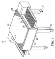
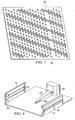
- compact conveyor oven 10 includes exterior front wall 12, exterior right side wall 14, exterior left side wall 16, exterior back wall 18, exterior bottom wall 20 and exterior top wall 22.
- Food products are transported into and through cooking chamber 24 by conveyor 28.
- the conveyor assembly 28 comprises a continuous loop wire mesh conveyor belt which extends through entrance opening 32 and exit opening 36.
- the width of belt 28 is approximately 32 inches (81.28 cm.) and the length of belt 28 within cooking chamber 24 is approximately 40 inches (101.6 cm.).
- the conveyor belt extends a sufficient distance from the entrance and exit openings of the oven to allow food products to be readily positioned on the conveyor belt for travel through the cooking chamber of the oven and removal upon exiting the oven.
- Compact conveyor oven 10 may be supported by legs 25 and movable by rollers 27 or may sit on a shelf or table top, or be stacked one above another.
- the compact conveyor oven is comprised of two independently controlled gas transfer systems, described herein as a top gas transfer system and a bottom gas transfer system and although the top and bottom gas transfer systems are identical, it is not required that they be identical. Described herein in detail is the top gas transfer system.
- the bottom system is made, functions and operates in the same manner as the top system.
- gas refers to any fluid mixture, including air, nitrogen and other mixtures that may be used for cooking, and applicant intends to encompass within the language and meaning any gas or gas mixture existing or developed in the future that performs the same function.
- airflow refers to, and includes gas flow.
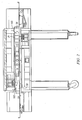
- Top gas delivery system 40 FIG. 4 delivers temperature-controlled gas to the top side of conveyor belt 28 and lower gas delivery system 42 delivers gas to the bottom side of belt 28.
- Independent control of top and bottom gas transfer systems 40, 42 is known and further described in US 5,717,192 .
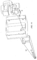
- Top gas delivery system 40 is comprised of gas flow means 50, 60, 62, FIG. 5 , and top gas transfer section 41, FIG. 9 .
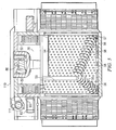
- Gas transfer section 41 is comprised of nozzle plate 54, turning vanes 56, and gas transfer section side walls 41a-d and top wall 41e. Although section 41 is illustrated as tapered toward the back of oven 10, there is no requirement for such tapering.
- Nozzle plate 54 is further comprised of nozzle sections 55, 57, described further herein, and nozzles 58.
- Variable speed blower motors and variable speed blower motor controllers may be utilized, but there is no requirement for their use and indeed the compact conveyor oven of the present invention may avoid the problems and complexity of variable speed blower motors by maintaining a constant gas flow, or alternatively, a substantially constant gas glow rate through the oven cooking chamber, gas transfer and gas delivery systems.
- Gas flows may be very aggressive, or less aggressive, depending upon the cooking requirements for each food product and one means to achieve gas flow modulation is by use of a gas pumping means such as a blower motor, blower wheel combination, utilizing a controller or a multi speed switch that allows for the switching of the blower motor speed in pre-determined fixed increments.
- blower motor shaft 60 Connected to top blower wheel 50 is blower motor shaft 60, which is direct drive with electric motor 62, FIG. 5 .
- Other means may be employed for coupling blower wheel 50 to electric motor 62, such as belt drive and the drive means is not limited to direct drive and applicant intends to encompass within the language any structure presently existing or developed in the future that performs the same function.
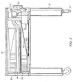
- Gas is heated within combustion chamber 70, FIG. 5 by a gas combustion burner assembly 80 prior to delivery to blower wheel 50.
- Blower wheel 50 discharges gas into nozzle section 55 of gas transfer section 41 toward the front wall of oven 10.
- the gas flow is then re-directed by vanes 56 and thereafter flows to larger nozzle section 57.
- Gas flow to larger section 57 pressurizes entire nozzle plate 54 allowing for substantially equal pressures throughout section 41.
- Substantially equal pressure throughout section 41 provides for substantially equal impingement of gas flow through nozzles 54 and onto the top of food product.
- Apertures 54 may be slotted, regularly formed or irregularly formed apertures and are illustrated herein as uniform nozzles, FIG. 7 , and applicant intends to encompass within the meaning of nozzle any structure presently existing or developed in the future that performs the same function as nozzles 54 and as used herein the term "aperture" and "nozzle” have the same meaning.
- Apertures 54 are sized for a low pressure drop, while providing and maintaining sufficient gas velocities in the range of approximately 2000 ft/minute (609.6 meters/minute) to approximately 6000 ft/minute (1828.80 meters/minute) to properly cook the food product as described herein. In some instances, velocities below 2000 ft/minute (609.6 meters/minute) or above 6000 ft/minute (1828.80 meters/minute) may also be utilized, depending upon the particular food product to be cooked, or a particular cooking recipe that the controller is executing, and applicant does not intend to limit the invention to gas velocities within a particular range. Apertures 54 are sized such that substantially equivalent velocities of gas impinges against the top surface of belt 28.
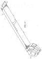
- the gas flows traveling up walls 41a and 41c is re-directed by deflecting vanes 102 for return to heating chamber 70, FIG.5 .
- Deflecting vanes 102 force gas to travel in a substantially uniform manner, thereby preventing short circuiting of the gas traveling up walls 41a, 41c toward the back of oven 10.
- gas toward the tapered end of section 41 (back wall 41d) would have shorter distance to travel and therefore would make more revolutions or cycles through the oven than gas returning further away from front wall 12 of oven 10.
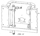
- Gas returning to heating chamber 70 may be reheated by gas combustion burner 80, FIGS. 5 , 8 , 10 .
- combustion gas burner 80 is placed between blower wheels 50, 52. Placement of combustion burner 80 between blower wheels 50,52 sometimes requires burner 80 to be fitted with a burner tube, 103 FIG. 8 .
- burner tube 108 is adjusted ("tuned") to allow a sufficient amount of make-up air to enter tube 103. Gas combustion occurs within tube 103 and then passes through apertures 105 for delivery to oven cavity 24.
- cooling duct 110 Portions of compact oven 10 are cooled by cooling duct 110, FIG. 12 wherein fresh air is drawn through intake opening 112 by motor 111 and distributed throughout oven 10 as required. Placement of cooling duct 110 along the back of oven wall 18 provides spacing such that oven 10 cannot be positioned directly adjacent a wall or other structure or device because cooling duct 110 forms a self spacing air path in addition to a cooling mechanism for oven 10. In order to allow for additional footprint savings, gas plumbing pipe, 115, FIG. 11 is located within back wall 18 of oven 10. This allows one oven to be easily stacked upon another such oven.
- top and bottom gas supply systems are the same configuration and function to uniformly circulate hot gas flow to the top and bottom sides of food product upon belt 28, and return the gas to the gas heating means for re-delivery to the cooking chamber.
- the number and placement of the apertures 58 will vary according to the particular oven that is desired.
- a general purpose compact conveyor oven may be scaled to a baking oven by changing the number of apertures, which may be fewer in number but be larger in size, thereby allowing for a more gentle gas flow across the food product, and producing proper delicate baking of the food product.
- the apertures may be more numerous and smaller in diameter.
- the operator may desire more flexibility of cooking nozzle plates 54 may be fabricated in a manner that allows for quick change-out of the plates by the operator.
- the gas flow within the conveyor oven, as well as other functions of cooking appliance 10 are directed by a controller, not shown.
- the controller determines, among other things, the velocity of gas flow, which may be constant or varied, or, may be constantly varied throughout the cooking cycle. It may be desired to cook the food product on one velocity throughout the entire cooking cycle, or to vary the gas velocity depending upon conditions such as a pre-determined cooking recipes, or vary the gas velocity in response to various sensors that may be placed within the cooking zone, oven return gas paths or various other positions within the oven. The location and placement of said sensors will be determined by the particular application of the oven. Additionally, other means may be utilized wherein data is transmitted back to the controller, and thereafter the controller adjusts the cooking recipe in an appropriate manner.
- sensors temperature, humidity, velocity, vision and gas borne chemical mixture level sensors
- the compact cooking conveyor oven may utilize sensors that are not currently commercially practical due to cost or other limitations (such as laser, non-invasive temperature sensors, IR sensors and laser to locate the sensed area and other sensors that are currently too expensive to be commercially feasible), and the oven is not limited to those discussed herein, as many sensing devices are known and utilized in and applicant intends to encompass within the language any structure presently existing or developed in the future that performs the same function.
- lower nozzle plate 59 contains channels or grooves that allow conveyor belt runners 61, FIG. 6 of conveyor belt 28 to ride or glide within channels 59, thereby enabling belt 28 to be located closer to lower nozzles 58.
- Location of belt 28 closer to nozzles 58 allows for higher heat transfer rates to the bottom sides of food products upon belt 28.
- Conveyor belt 28 is fitted with floating bearings 66, FIG. 6 that allow for simplified maintenance and tensioning of belt 28.
- the exemplary embodiment illustrates the use of a two blower design with one blower providing the gas flow to the top of the cooking cavity and a second blower for gas flow to the bottom of the cooking cavity
- one gs flow means may be utilized, or more than two gas flow means may be utilized and applicant intends to encompass within the language any structure presently existing or developed in the future that performs the same function.
- the present invention provides for a compact conveyor oven utilizing hot gas flow, supplied from combustion energy in order to achieve faster cooking of food products.
- the compact conveyor oven is simple and economical to manufacture, use and maintain, and is directly scalable to larger or smaller embodiments.
Landscapes
- Life Sciences & Earth Sciences (AREA)
- Engineering & Computer Science (AREA)
- Food Science & Technology (AREA)
- Baking, Grill, Roasting (AREA)
- Electric Stoves And Ranges (AREA)
Claims (11)
- Ein kompakter Durchlaufofen (10) zum Kochen eines Nahrungsmittelproduktes enthaltend:einen Garraum (24);ein Gaszufuhrsystem (40);eine Strömungseinrichtung (50, 52), um das Gas zirkulieren zu lassen;einen ersten Gasübertragungsabschnitt (41), der über dem Nahrungsmittelprodukt angeordnet ist und betriebsfähig mit der Strömungseinrichtung (50, 52) verbunden ist;der erste Gasübertragungsabschnitt (41) umfasst ferner eine Trennwand;wobei die Trennwand den ersten Gasübertragungsabschnitt (41) in einen kleineren und einen größeren Düsenabschnitt (55, 57) aufteilt;wobei jeder Düsenabschnitt eine Mehrzahl von Düsen (58) umfasst;gekennzeichnet durch das Vorhandensein von Umlenkblechen (56) innerhalb des ersten Gasübertragungsabschnittes (41);
wobei Gas aus der Strömungseinrichtung (50, 52) in den kleineren Düsenabschnitt (55) entladen wird und danach in den größeren Düsenabschnitt (57) durch die Umlenkbleche (56) umgelenkt wird; und
wobei im Wesentlichen gleiche Druckbeaufschlagung des Gases erreicht wird, das durch die Düsen (58) des ersten Übertragungsabschnittes (41) strömt. - Der Ofen (10) gemäß Anspruch 1 ferner umfassend:einen zweiten Gasübertragungsabschnitt (42), der unter dem Nahrungsmittelprodukt angeordnet ist und betriebsfähig mit der Strömungseinrichtung (50, 52) verbunden ist;wobei der zweite Gasübertragungsabschnitt (42) ferner eine Trennwand umfasst;wobei die Trennwand den zweiten Gasübertragungsabschnitt (42) in einen kleineren (55) und einen größeren (57) Düsenabschnitt aufteilt;wobei jeder der kleinere (55) und der größere (57) Düsenabschnitt eine Mehrzahl von Düsen (58) aufweist;wobei Umlenkbleche (56) innerhalb des zweiten Gasübertragungsabschnittes (42) angeordnet sind;wobei Gas aus der Strömungseinrichtung (50, 52) in den kleineren Düsenabschnitt (55) entladen wird und in den größeren Düsenabschnitt (57) durch die Umlenkbleche (56) umgelenkt wird; undwobei im Wesentlichen gleiche Druckbeaufschlagung des Gases erreicht wird, das durch die Düsen (58) des zweiten Übertragungsabschnitts (42) strömt.
- Der Ofen (10) gemäß Anspruch 2, wobei der erste Gasübertragungsabschnitt (41) unabhängig von dem zweiten Gasübertragungsabschnitt (42) arbeitet.
- Der Ofen (10) gemäß Anspruch 3 ferner umfassend eine Steuereinrichtung zur Steuerung des Gasstroms.
- Der Ofen (10) gemäß Anspruch 1, wobei die Strömungseinrichtung einen Gebläsemotor (62) aufweist.
- Der Ofen (10) gemäß Anspruch 5, wobei der Gebläsemotor (62) mit variablen Geschwindigkeiten läuft.
- Der Ofen (10) gemäß Anspruch 1 ferner umfassend Mittel (80) zum Erhitzen des Gases.
- Der Ofen (10) gemäß Anspruch 7, wobei das Mittel (80) zum Erhitzen des Gases elektrische Widerstandselemente darstellt.
- Der Ofen (10) gemäß Anspruch 7, wobei das Mittel (80) zum Erhitzen des Gases gasförmigen Brennstoff darstellt.
- Der Ofen (10) gemäß Anspruch 2, wobei mindestens eine Strömungseinrichtung (50, 52) Gas zu dem ersten (41) und zu dem zweiten (42) Gasübertragungsabschnitt liefert.
- Der Ofen (10) gemäß Anspruch 7, wobei das Mittel (80) zum Erhitzen des Gases direkt oder indirekt ist.
Applications Claiming Priority (2)
| Application Number | Priority Date | Filing Date | Title |
|---|---|---|---|
| US90639407P | 2007-03-10 | 2007-03-10 | |
| PCT/US2008/056358 WO2008112606A2 (en) | 2007-03-10 | 2008-03-10 | Compact conveyor oven |
Publications (2)
| Publication Number | Publication Date |
|---|---|
| EP2139341A2 EP2139341A2 (de) | 2010-01-06 |
| EP2139341B1 true EP2139341B1 (de) | 2016-11-16 |
Family
ID=39537921
Family Applications (1)
| Application Number | Title | Priority Date | Filing Date |
|---|---|---|---|
| EP08731778.0A Active EP2139341B1 (de) | 2007-03-10 | 2008-03-10 | Kompakter durchlaufofen |
Country Status (3)
| Country | Link |
|---|---|
| US (1) | US8113190B2 (de) |
| EP (1) | EP2139341B1 (de) |
| WO (1) | WO2008112606A2 (de) |
Families Citing this family (44)
| Publication number | Priority date | Publication date | Assignee | Title |
|---|---|---|---|---|
| EP1534999B1 (de) | 2002-07-05 | 2017-11-01 | TurboChef Technologies, Inc. | Schnellkochofen |
| US8006685B2 (en) * | 2002-07-05 | 2011-08-30 | Turbochef Technologies, Inc. | Re-circulating oven with gas clean-up |
| US9351495B2 (en) * | 2002-07-05 | 2016-05-31 | Turbochef Technologies, Inc. | Air fryer |
| US20070006865A1 (en) | 2003-02-21 | 2007-01-11 | Wiker John H | Self-cleaning oven |
| US8658953B2 (en) * | 2003-07-07 | 2014-02-25 | Turbochef Technologies, Inc. | Antenna cover for microwave ovens |
| US8035062B2 (en) * | 2003-07-07 | 2011-10-11 | Turbochef Technologies, Inc. | Combination speed cooking oven |
| US7886658B2 (en) * | 2003-07-07 | 2011-02-15 | Turbochef Technologies, Inc. | Speed cooking oven with improved radiant mode |
| US8011293B2 (en) * | 2003-07-07 | 2011-09-06 | Turbochef Technologies, Inc. | Speed cooking oven with sloped oven floor and reversing gas flow |
| US7946224B2 (en) * | 2003-07-07 | 2011-05-24 | Turbochef Technologies, Inc. | Griddle |
| US20080105249A1 (en) * | 2003-07-07 | 2008-05-08 | Turbochef Technologies, Inc. | Speed cooking oven with radiant mode |
| US20050056946A1 (en) * | 2003-09-16 | 2005-03-17 | Cookson Electronics, Inc. | Electrical circuit assembly with improved shock resistance |
| WO2005041672A2 (en) * | 2003-10-21 | 2005-05-12 | Global Appliance Technologies, Inc. | Speed cooking oven with slotted microwave antenna |
| JP2007527299A (ja) * | 2004-03-05 | 2007-09-27 | グローバル アプライアンス テクノロジーズ インコーポレイテッド | コンベヤオーブン |
| US9585400B2 (en) | 2004-03-23 | 2017-03-07 | The Middleby Corporation | Conveyor oven apparatus and method |
| US8087407B2 (en) | 2004-03-23 | 2012-01-03 | Middleby Corporation | Conveyor oven apparatus and method |
| US8210844B2 (en) * | 2008-10-27 | 2012-07-03 | Wolfe Electric, Inc. | Air impingement conveyor oven |
| US20110048244A1 (en) * | 2009-08-28 | 2011-03-03 | Wiker John H | Apparatus and method for controlling a combustion blower in a gas-fueled conveyor oven |
| US8839714B2 (en) | 2009-08-28 | 2014-09-23 | The Middleby Corporation | Apparatus and method for controlling a conveyor oven |
| US9288997B2 (en) | 2011-03-31 | 2016-03-22 | Ovention, Inc. | Matchbox oven |
| US9480364B2 (en) | 2011-03-31 | 2016-11-01 | Ovention, Inc. | Oven having an H-shaped rotating door |
| US9326639B2 (en) | 2011-03-31 | 2016-05-03 | Ovention, Inc. | Oven having a rotating door |
| US8733236B2 (en) | 2011-09-20 | 2014-05-27 | Ovention, Inc. | Matchbox oven |
| KR102099726B1 (ko) | 2012-12-04 | 2020-04-13 | 인고 스토르크 게난트 베르스보르그 | 열처리 모니터링 시스템 |
| JP5541353B1 (ja) * | 2012-12-28 | 2014-07-09 | 千住金属工業株式会社 | 気体吸込み孔の配列構造及びはんだ付け装置 |
| JP5541354B1 (ja) * | 2012-12-28 | 2014-07-09 | 千住金属工業株式会社 | 気体吹き出し孔の配列構造及びはんだ付け装置 |
| WO2014139099A1 (en) * | 2013-03-13 | 2014-09-18 | China Sunergy (Nanjing) Co., Ltd. | Soldering system |
| US9372006B2 (en) | 2013-05-06 | 2016-06-21 | Ovention, Inc. | Compact oven |
| US9879865B2 (en) | 2015-06-08 | 2018-01-30 | Alto-Shaam, Inc. | Cooking oven |
| US10088172B2 (en) | 2016-07-29 | 2018-10-02 | Alto-Shaam, Inc. | Oven using structured air |
| US10337745B2 (en) | 2015-06-08 | 2019-07-02 | Alto-Shaam, Inc. | Convection oven |
| US9677774B2 (en) | 2015-06-08 | 2017-06-13 | Alto-Shaam, Inc. | Multi-zone oven with variable cavity sizes |
| US10890336B2 (en) | 2015-06-08 | 2021-01-12 | Alto-Shaam, Inc. | Thermal management system for multizone oven |
| NZ746496A (en) * | 2016-03-09 | 2021-12-24 | Dmp Entpr Pty Ltd | Conveyor-type oven |
| US10258066B2 (en) * | 2016-07-18 | 2019-04-16 | Washington State University | Microwave sterilization or pasteurization transport carriers and system |
| WO2018187460A2 (en) * | 2017-04-07 | 2018-10-11 | The Middleby Corporation | Conveyor oven apparatus and method |
| US10746410B2 (en) | 2017-06-29 | 2020-08-18 | The Middleby Corporation | Cooking oven power modulation system and method |
| US11206946B2 (en) | 2018-03-21 | 2021-12-28 | Marmon Foodservice Technologies, Inc. | Heat transfer system |
| US20220202021A1 (en) * | 2019-06-19 | 2022-06-30 | De Luca Oven Technologies, Llc | Dynamic Modulation and Binarization of Heating Profile and Conveyance System within an Oven for Heating Based on Energy Availability |
| US12016107B2 (en) | 2020-03-19 | 2024-06-18 | Texas Research International, Inc. | Continuous mode conveyor cooking utilizing hot air jet impingement and microwave energy |
| CN215305176U (zh) * | 2021-06-15 | 2021-12-28 | 江门市新会恒隆家居创新用品有限公司 | 多士炉 |
| US20230313990A1 (en) * | 2022-03-30 | 2023-10-05 | Nala Robotics, Inc. | Systems and methods for a gas train |
| USD1113323S1 (en) | 2023-08-04 | 2026-02-17 | Marmon Foodservice Technologies, Inc. | Toaster |
| US12599983B2 (en) * | 2023-09-11 | 2026-04-14 | Taiwan Semiconductor Manufacturing Company, Ltd. | Semiconductor processing tool and methods of operation |
| CN118252168A (zh) * | 2024-04-25 | 2024-06-28 | 佛山市顺德区奥利焙食品机械有限公司 | 一种受热均匀的循环式食品隧道烘干炉 |
Citations (2)
| Publication number | Priority date | Publication date | Assignee | Title |
|---|---|---|---|---|
| EP0419213A2 (de) * | 1989-09-22 | 1991-03-27 | Patentsmith Ii, Inc. | Umluftofen mit geregeltem Luftrücklauf |
| US20050045173A1 (en) * | 2003-08-28 | 2005-03-03 | Heber Albert J. | Dual conveyor jet impingement oven |
Family Cites Families (74)
| Publication number | Priority date | Publication date | Assignee | Title |
|---|---|---|---|---|
| US2028944A (en) * | 1929-06-20 | 1936-01-28 | Republic Metalware Company | Toasting machine |
| US2264525A (en) * | 1940-07-31 | 1941-12-02 | Hall Zachariah Adam | Kitchen range |
| US2704802A (en) | 1952-05-22 | 1955-03-22 | Raytheon Mfg Co | Microwave ovens |
| GB977777A (en) | 1962-02-02 | 1964-12-16 | Lyons & Co Ltd J | Improvements in or relating to radio frequency ovens |
| BE789508A (fr) | 1971-10-08 | 1973-01-15 | Werner & Pfleiderer | Four tunnel continu de cuisson ou de sechage |
| US3828760A (en) | 1973-05-23 | 1974-08-13 | Lca Corp | Oven |
| DE2557867C3 (de) | 1975-12-22 | 1979-11-08 | Bosch-Siemens Hausgeraete Gmbh, 7000 Stuttgart | Umluftofen |
| US4338911A (en) | 1976-05-19 | 1982-07-13 | Smith Donald P | Cooking apparatus |
| US4154861A (en) | 1976-05-19 | 1979-05-15 | Smith Donald P | Heat treatment of food products |
| US4409453A (en) | 1976-05-19 | 1983-10-11 | Smith Donald P | Combined microwave and impingement heating apparatus |
| US4283614A (en) | 1978-02-20 | 1981-08-11 | Matsushita Electric Industrial Co., Ltd. | Cooking device with high-frequency heating means and resistance heating means |
| CA1114262A (en) | 1979-01-16 | 1981-12-15 | Raytheon Company | Gas burner convection oven |
| US4337384A (en) | 1979-08-01 | 1982-06-29 | Matsushita Electric Industrial Co., Ltd. | Cooking appliance of the hot air circulating type |
| US4327279A (en) | 1979-11-27 | 1982-04-27 | Sunsetl, Ltd. | Counter-top reheating unit for packaged pre-cooked meals |
| US4431889A (en) | 1981-11-09 | 1984-02-14 | Raytheon Company | Combination microwave and convection oven |
| US4576090A (en) * | 1982-05-19 | 1986-03-18 | Mastermatic, Inc. | Tunnel heater |
| US4462383A (en) | 1982-06-09 | 1984-07-31 | Lincoln Manufacturing Company, Inc. | Impingement food preparation apparatus |
| US4464554A (en) | 1982-08-25 | 1984-08-07 | General Electric Company | Dynamic bottom feed for microwave ovens |
| US4480164A (en) | 1982-12-03 | 1984-10-30 | General Electric Company | Food browning system incorporating a combined microwave and hot air oven |
| US4626661A (en) * | 1984-04-16 | 1986-12-02 | Lincoln Manufacturing Company, Inc. | Air delivery system for an impingement food preparation oven |
| US4556043A (en) * | 1984-09-17 | 1985-12-03 | Lincoln Manufacturing Company, Inc. | Air delivery system for an impingement food preparation oven including a conical air deflector |
| US4591333A (en) * | 1985-03-26 | 1986-05-27 | Lincoln Manufacturing Company, Inc. | Impingement oven with radiant panel |
| JPS6230635A (ja) | 1985-07-30 | 1987-02-09 | Chugai Ro Kogyo Kaisha Ltd | ブラウン管排気炉 |
| US4965435A (en) | 1985-10-15 | 1990-10-23 | Donald P. Smith | Forced convection tunnel oven |
| US4757800A (en) * | 1987-01-14 | 1988-07-19 | Lincoln Foodservice Products, Inc. | Air flow system for a low profile impingement oven |
| JPS63317068A (ja) | 1987-06-19 | 1988-12-26 | Toppan Printing Co Ltd | 高周波加熱・殺菌方法 |
| AU3436289A (en) * | 1988-03-10 | 1989-10-05 | Pizza Hut Inc. | Method and oven for baking pizza |
| US4958412A (en) | 1988-12-09 | 1990-09-25 | W. R. Grace & Co.-Conn. | Method and apparatus for coating a food product |
| US4960100A (en) * | 1989-03-13 | 1990-10-02 | Mastermatic, Inc. | Conveyor oven |
| US4951648A (en) * | 1989-03-23 | 1990-08-28 | Tecogen, Inc. | Conveyor oven |
| US6041398A (en) * | 1992-06-26 | 2000-03-21 | International Business Machines Corporation | Massively parallel multiple-folded clustered processor mesh array |
| IT1236295B (it) | 1989-11-29 | 1993-02-02 | Zanussi Grandi Impianti Spa | Forno di cottura combinato a microonde e convenzione forzata |
| US5166487A (en) * | 1989-12-15 | 1992-11-24 | Tecogen, Inc. | Cooking oven with convection and microwave heating |
| US5401940A (en) * | 1990-01-10 | 1995-03-28 | Patentsmith Ii, Inc. | Oscillating air dispensers for microwave oven |
| US5717192A (en) | 1990-01-10 | 1998-02-10 | Patentsmith Technology, Ltd. | Jet impingement batch oven |
| US5025775A (en) * | 1990-06-04 | 1991-06-25 | Lincoln Foodservice Products, Inc. | Air delivery system and oven control circuitry cooling system for a low profile impingement oven |
| US5161889A (en) | 1991-06-03 | 1992-11-10 | Patentsmith Ii, Inc. | Heat transfer rate target module |
| DE69206736T2 (de) | 1991-09-27 | 1996-05-30 | Apv Uk Plc | Geräte zur Mikrowellenerhitzung |
| US5277105A (en) * | 1992-05-29 | 1994-01-11 | Middleby Marshall Corporation | Low profile stackable conveyor oven |
| CA2191730A1 (en) | 1994-05-25 | 1995-11-30 | Dennis Wassman | Convectively-enhanced radiant heat oven |
| US5421320A (en) * | 1994-05-27 | 1995-06-06 | Ldi Mfg. Co., Inc. | Conveyor oven exhaust system |
| US5994672A (en) | 1996-05-17 | 1999-11-30 | Air Fry, Inc. | Oil-free fryer, food cooker |
| US5826496A (en) | 1996-07-23 | 1998-10-27 | Stein, Inc. | Cooking oven |
| KR19980017873A (ko) | 1996-08-31 | 1998-06-05 | 배순훈 | 전자렌지의 도파관 구조 |
| US5964044A (en) * | 1997-01-14 | 1999-10-12 | Wisconsin Oven Corporation | Conveyor oven usable as pre-bake oven in a print plate imaging and processing system and method of using same |
| US6058924A (en) | 1997-05-27 | 2000-05-09 | Turbochef Technologies, Inc. | Vented recycling oven with separate catalytic converter |
| US6060701A (en) | 1997-05-27 | 2000-05-09 | Turbochef Technologies, Inc. | Compact quick-cooking convectional oven |
| JP3717403B2 (ja) | 1998-02-19 | 2005-11-16 | フラマトム アンプ ゲゼルシャフト ミット ベシュレンクテル ハフツング | 核燃料のマイクロ波焼結方法及び装置 |
| US6376817B1 (en) | 1998-10-09 | 2002-04-23 | Turbochef Technologies, Inc. | Compact quick-cooking oven |
| US6369360B1 (en) | 1999-05-21 | 2002-04-09 | Maytag Corporation | Combination high speed infrared and convection conveyor oven and method of using |
| GB2341677B (en) | 1999-11-20 | 2000-12-27 | Merrychef Ltd | Ovens with catalytic converters |
| US6234161B1 (en) * | 2000-01-20 | 2001-05-22 | Maytag Corporation | Gas cooking appliance with isolated combustion and cooling air flows |
| DE10107289A1 (de) | 2000-03-14 | 2001-09-27 | Werner & Pfleiderer Lebensmitt | Durchlauf-Backofen |
| US6403937B1 (en) | 2000-07-08 | 2002-06-11 | The Garland Group | Combination convection/microwave oven controller |
| US6576874B2 (en) * | 2001-09-06 | 2003-06-10 | Bakers Pride | Modular heating element for a conveyor oven |
| US6592364B2 (en) * | 2001-11-30 | 2003-07-15 | David Zapata | Apparatus, method and system for independently controlling airflow in a conveyor oven |
| WO2005087009A1 (en) | 2003-07-07 | 2005-09-22 | Global Appliance Technologies, Inc. | Conveyor oven |
| EP1534999B1 (de) | 2002-07-05 | 2017-11-01 | TurboChef Technologies, Inc. | Schnellkochofen |
| US8006685B2 (en) | 2002-07-05 | 2011-08-30 | Turbochef Technologies, Inc. | Re-circulating oven with gas clean-up |
| US7886658B2 (en) | 2003-07-07 | 2011-02-15 | Turbochef Technologies, Inc. | Speed cooking oven with improved radiant mode |
| US7946224B2 (en) | 2003-07-07 | 2011-05-24 | Turbochef Technologies, Inc. | Griddle |
| US20080105249A1 (en) | 2003-07-07 | 2008-05-08 | Turbochef Technologies, Inc. | Speed cooking oven with radiant mode |
| US8011293B2 (en) | 2003-07-07 | 2011-09-06 | Turbochef Technologies, Inc. | Speed cooking oven with sloped oven floor and reversing gas flow |
| US8658953B2 (en) | 2003-07-07 | 2014-02-25 | Turbochef Technologies, Inc. | Antenna cover for microwave ovens |
| WO2005041672A2 (en) | 2003-10-21 | 2005-05-12 | Global Appliance Technologies, Inc. | Speed cooking oven with slotted microwave antenna |
| ITMI20032119A1 (it) * | 2003-11-04 | 2005-05-05 | Oem Ali S P A | Forno ventilato ad alimentazione trasformabile per prodotti alimentari |
| JP2007527299A (ja) | 2004-03-05 | 2007-09-27 | グローバル アプライアンス テクノロジーズ インコーポレイテッド | コンベヤオーブン |
| US8087407B2 (en) * | 2004-03-23 | 2012-01-03 | Middleby Corporation | Conveyor oven apparatus and method |
| BRPI0516534A (pt) | 2004-10-05 | 2008-09-09 | Turbochef Tech Inc | forno de recirculação com limpeza a gás |
| CA2589319C (en) | 2004-12-03 | 2014-05-13 | Turbochef Technologies, Inc. | High speed convection oven |
| CA2595820A1 (en) * | 2005-01-26 | 2006-08-03 | Enersyst Development Center, Llc | High efficiency fluid delivery system |
| US20080092874A1 (en) * | 2006-09-14 | 2008-04-24 | Greg Kolecki | Overhead ventilation system incorporating a downwardly configured rear supply plenum with upward configured and reverse bended directional outlet |
| US7604000B2 (en) * | 2006-12-21 | 2009-10-20 | Wolfe Electric, Inc. | Tunnel oven |
| US20090139976A1 (en) * | 2007-12-03 | 2009-06-04 | Robert Lee | Impingement quartz conveyor oven |
-
2008
- 2008-03-10 US US12/045,063 patent/US8113190B2/en active Active
- 2008-03-10 WO PCT/US2008/056358 patent/WO2008112606A2/en not_active Ceased
- 2008-03-10 EP EP08731778.0A patent/EP2139341B1/de active Active
Patent Citations (2)
| Publication number | Priority date | Publication date | Assignee | Title |
|---|---|---|---|---|
| EP0419213A2 (de) * | 1989-09-22 | 1991-03-27 | Patentsmith Ii, Inc. | Umluftofen mit geregeltem Luftrücklauf |
| US20050045173A1 (en) * | 2003-08-28 | 2005-03-03 | Heber Albert J. | Dual conveyor jet impingement oven |
Also Published As
| Publication number | Publication date |
|---|---|
| EP2139341A2 (de) | 2010-01-06 |
| US20080216812A1 (en) | 2008-09-11 |
| WO2008112606A2 (en) | 2008-09-18 |
| WO2008112606A3 (en) | 2008-12-24 |
| US8113190B2 (en) | 2012-02-14 |
Similar Documents
| Publication | Publication Date | Title |
|---|---|---|
| EP2139341B1 (de) | Kompakter durchlaufofen | |
| EP2074369B1 (de) | Beeinflussung von umluftherden mit öffnungen für hohen massenfluss | |
| US6817283B2 (en) | High speed cooking device and method | |
| EP0086568B1 (de) | Wärmebehandlung von Nahrungsmittelprodukten | |
| EP1199963B1 (de) | Schneller toaster mit variabelen dimensionen | |
| AU635560B2 (en) | Balanced air return convection oven | |
| US20140261371A1 (en) | Conveyor oven with split flow scroll | |
| JP5545422B1 (ja) | 加温ユニット及びこれを搭載したトンネルオーブン | |
| WO2002076218A1 (en) | Multiconveyor convection oven | |
| HK1052837A1 (zh) | 輸送帶式烤爐 | |
| AU2018250201B2 (en) | Conveyor oven heat delivery system | |
| AU2018250200B2 (en) | Conveyor oven apparatus and method | |
| US6557543B2 (en) | High pressure airflow and duct distribution system for a convection oven | |
| WO2018010000A1 (en) | Methods and apparatus for cooking food | |
| HK1135171B (en) | Impinging air ovens having high mass flow orifices |
Legal Events
| Date | Code | Title | Description |
|---|---|---|---|
| PUAI | Public reference made under article 153(3) epc to a published international application that has entered the european phase |
Free format text: ORIGINAL CODE: 0009012 |
|
| 17P | Request for examination filed |
Effective date: 20091008 |
|
| AK | Designated contracting states |
Kind code of ref document: A2 Designated state(s): AT BE BG CH CY CZ DE DK EE ES FI FR GB GR HR HU IE IS IT LI LT LU LV MC MT NL NO PL PT RO SE SI SK TR |
|
| RAP1 | Party data changed (applicant data changed or rights of an application transferred) |
Owner name: TURBOCHEF TECHNOLOGIES, INC. |
|
| 17Q | First examination report despatched |
Effective date: 20111222 |
|
| DAX | Request for extension of the european patent (deleted) | ||
| REG | Reference to a national code |
Ref country code: DE Ref legal event code: R079 Ref document number: 602008047391 Country of ref document: DE Free format text: PREVIOUS MAIN CLASS: A21B0001240000 Ipc: A21B0001480000 |
|
| RIC1 | Information provided on ipc code assigned before grant |
Ipc: A21B 1/24 20060101ALI20151008BHEP Ipc: A21B 1/48 20060101AFI20151008BHEP |
|
| GRAP | Despatch of communication of intention to grant a patent |
Free format text: ORIGINAL CODE: EPIDOSNIGR1 |
|
| INTG | Intention to grant announced |
Effective date: 20160616 |
|
| GRAS | Grant fee paid |
Free format text: ORIGINAL CODE: EPIDOSNIGR3 |
|
| GRAA | (expected) grant |
Free format text: ORIGINAL CODE: 0009210 |
|
| AK | Designated contracting states |
Kind code of ref document: B1 Designated state(s): AT BE BG CH CY CZ DE DK EE ES FI FR GB GR HR HU IE IS IT LI LT LU LV MC MT NL NO PL PT RO SE SI SK TR |
|
| REG | Reference to a national code |
Ref country code: GB Ref legal event code: FG4D |
|
| RIN1 | Information on inventor provided before grant (corrected) |
Inventor name: DOUGHERTY, CARL, J. |
|
| REG | Reference to a national code |
Ref country code: CH Ref legal event code: EP |
|
| REG | Reference to a national code |
Ref country code: IE Ref legal event code: FG4D |
|
| REG | Reference to a national code |
Ref country code: AT Ref legal event code: REF Ref document number: 844999 Country of ref document: AT Kind code of ref document: T Effective date: 20161215 |
|
| REG | Reference to a national code |
Ref country code: DE Ref legal event code: R096 Ref document number: 602008047391 Country of ref document: DE |
|
| REG | Reference to a national code |
Ref country code: NL Ref legal event code: FP |
|
| PG25 | Lapsed in a contracting state [announced via postgrant information from national office to epo] |
Ref country code: LV Free format text: LAPSE BECAUSE OF FAILURE TO SUBMIT A TRANSLATION OF THE DESCRIPTION OR TO PAY THE FEE WITHIN THE PRESCRIBED TIME-LIMIT Effective date: 20161116 |
|
| REG | Reference to a national code |
Ref country code: LT Ref legal event code: MG4D Ref country code: FR Ref legal event code: PLFP Year of fee payment: 10 |
|
| PG25 | Lapsed in a contracting state [announced via postgrant information from national office to epo] |
Ref country code: NO Free format text: LAPSE BECAUSE OF FAILURE TO SUBMIT A TRANSLATION OF THE DESCRIPTION OR TO PAY THE FEE WITHIN THE PRESCRIBED TIME-LIMIT Effective date: 20170216 Ref country code: LT Free format text: LAPSE BECAUSE OF FAILURE TO SUBMIT A TRANSLATION OF THE DESCRIPTION OR TO PAY THE FEE WITHIN THE PRESCRIBED TIME-LIMIT Effective date: 20161116 Ref country code: SE Free format text: LAPSE BECAUSE OF FAILURE TO SUBMIT A TRANSLATION OF THE DESCRIPTION OR TO PAY THE FEE WITHIN THE PRESCRIBED TIME-LIMIT Effective date: 20161116 Ref country code: GR Free format text: LAPSE BECAUSE OF FAILURE TO SUBMIT A TRANSLATION OF THE DESCRIPTION OR TO PAY THE FEE WITHIN THE PRESCRIBED TIME-LIMIT Effective date: 20170217 |
|
| PG25 | Lapsed in a contracting state [announced via postgrant information from national office to epo] |
Ref country code: ES Free format text: LAPSE BECAUSE OF FAILURE TO SUBMIT A TRANSLATION OF THE DESCRIPTION OR TO PAY THE FEE WITHIN THE PRESCRIBED TIME-LIMIT Effective date: 20161116 Ref country code: PT Free format text: LAPSE BECAUSE OF FAILURE TO SUBMIT A TRANSLATION OF THE DESCRIPTION OR TO PAY THE FEE WITHIN THE PRESCRIBED TIME-LIMIT Effective date: 20170316 Ref country code: HR Free format text: LAPSE BECAUSE OF FAILURE TO SUBMIT A TRANSLATION OF THE DESCRIPTION OR TO PAY THE FEE WITHIN THE PRESCRIBED TIME-LIMIT Effective date: 20161116 Ref country code: PL Free format text: LAPSE BECAUSE OF FAILURE TO SUBMIT A TRANSLATION OF THE DESCRIPTION OR TO PAY THE FEE WITHIN THE PRESCRIBED TIME-LIMIT Effective date: 20161116 Ref country code: FI Free format text: LAPSE BECAUSE OF FAILURE TO SUBMIT A TRANSLATION OF THE DESCRIPTION OR TO PAY THE FEE WITHIN THE PRESCRIBED TIME-LIMIT Effective date: 20161116 |
|
| PG25 | Lapsed in a contracting state [announced via postgrant information from national office to epo] |
Ref country code: CZ Free format text: LAPSE BECAUSE OF FAILURE TO SUBMIT A TRANSLATION OF THE DESCRIPTION OR TO PAY THE FEE WITHIN THE PRESCRIBED TIME-LIMIT Effective date: 20161116 Ref country code: RO Free format text: LAPSE BECAUSE OF FAILURE TO SUBMIT A TRANSLATION OF THE DESCRIPTION OR TO PAY THE FEE WITHIN THE PRESCRIBED TIME-LIMIT Effective date: 20161116 Ref country code: EE Free format text: LAPSE BECAUSE OF FAILURE TO SUBMIT A TRANSLATION OF THE DESCRIPTION OR TO PAY THE FEE WITHIN THE PRESCRIBED TIME-LIMIT Effective date: 20161116 Ref country code: DK Free format text: LAPSE BECAUSE OF FAILURE TO SUBMIT A TRANSLATION OF THE DESCRIPTION OR TO PAY THE FEE WITHIN THE PRESCRIBED TIME-LIMIT Effective date: 20161116 Ref country code: SK Free format text: LAPSE BECAUSE OF FAILURE TO SUBMIT A TRANSLATION OF THE DESCRIPTION OR TO PAY THE FEE WITHIN THE PRESCRIBED TIME-LIMIT Effective date: 20161116 |
|
| REG | Reference to a national code |
Ref country code: DE Ref legal event code: R097 Ref document number: 602008047391 Country of ref document: DE |
|
| PG25 | Lapsed in a contracting state [announced via postgrant information from national office to epo] |
Ref country code: BE Free format text: LAPSE BECAUSE OF FAILURE TO SUBMIT A TRANSLATION OF THE DESCRIPTION OR TO PAY THE FEE WITHIN THE PRESCRIBED TIME-LIMIT Effective date: 20161116 Ref country code: IT Free format text: LAPSE BECAUSE OF FAILURE TO SUBMIT A TRANSLATION OF THE DESCRIPTION OR TO PAY THE FEE WITHIN THE PRESCRIBED TIME-LIMIT Effective date: 20161116 Ref country code: BG Free format text: LAPSE BECAUSE OF FAILURE TO SUBMIT A TRANSLATION OF THE DESCRIPTION OR TO PAY THE FEE WITHIN THE PRESCRIBED TIME-LIMIT Effective date: 20170216 |
|
| PLBE | No opposition filed within time limit |
Free format text: ORIGINAL CODE: 0009261 |
|
| STAA | Information on the status of an ep patent application or granted ep patent |
Free format text: STATUS: NO OPPOSITION FILED WITHIN TIME LIMIT |
|
| 26N | No opposition filed |
Effective date: 20170817 |
|
| REG | Reference to a national code |
Ref country code: CH Ref legal event code: PL |
|
| PG25 | Lapsed in a contracting state [announced via postgrant information from national office to epo] |
Ref country code: SI Free format text: LAPSE BECAUSE OF FAILURE TO SUBMIT A TRANSLATION OF THE DESCRIPTION OR TO PAY THE FEE WITHIN THE PRESCRIBED TIME-LIMIT Effective date: 20161116 Ref country code: MC Free format text: LAPSE BECAUSE OF FAILURE TO SUBMIT A TRANSLATION OF THE DESCRIPTION OR TO PAY THE FEE WITHIN THE PRESCRIBED TIME-LIMIT Effective date: 20161116 |
|
| REG | Reference to a national code |
Ref country code: IE Ref legal event code: MM4A |
|
| PG25 | Lapsed in a contracting state [announced via postgrant information from national office to epo] |
Ref country code: LU Free format text: LAPSE BECAUSE OF NON-PAYMENT OF DUE FEES Effective date: 20170310 |
|
| REG | Reference to a national code |
Ref country code: FR Ref legal event code: PLFP Year of fee payment: 11 |
|
| PG25 | Lapsed in a contracting state [announced via postgrant information from national office to epo] |
Ref country code: IE Free format text: LAPSE BECAUSE OF NON-PAYMENT OF DUE FEES Effective date: 20170310 Ref country code: CH Free format text: LAPSE BECAUSE OF NON-PAYMENT OF DUE FEES Effective date: 20170331 Ref country code: LI Free format text: LAPSE BECAUSE OF NON-PAYMENT OF DUE FEES Effective date: 20170331 |
|
| PG25 | Lapsed in a contracting state [announced via postgrant information from national office to epo] |
Ref country code: MT Free format text: LAPSE BECAUSE OF NON-PAYMENT OF DUE FEES Effective date: 20170310 |
|
| REG | Reference to a national code |
Ref country code: AT Ref legal event code: UEP Ref document number: 844999 Country of ref document: AT Kind code of ref document: T Effective date: 20161116 |
|
| PG25 | Lapsed in a contracting state [announced via postgrant information from national office to epo] |
Ref country code: HU Free format text: LAPSE BECAUSE OF FAILURE TO SUBMIT A TRANSLATION OF THE DESCRIPTION OR TO PAY THE FEE WITHIN THE PRESCRIBED TIME-LIMIT; INVALID AB INITIO Effective date: 20080310 |
|
| PG25 | Lapsed in a contracting state [announced via postgrant information from national office to epo] |
Ref country code: CY Free format text: LAPSE BECAUSE OF NON-PAYMENT OF DUE FEES Effective date: 20161116 |
|
| PG25 | Lapsed in a contracting state [announced via postgrant information from national office to epo] |
Ref country code: TR Free format text: LAPSE BECAUSE OF FAILURE TO SUBMIT A TRANSLATION OF THE DESCRIPTION OR TO PAY THE FEE WITHIN THE PRESCRIBED TIME-LIMIT Effective date: 20161116 |
|
| PG25 | Lapsed in a contracting state [announced via postgrant information from national office to epo] |
Ref country code: IS Free format text: LAPSE BECAUSE OF FAILURE TO SUBMIT A TRANSLATION OF THE DESCRIPTION OR TO PAY THE FEE WITHIN THE PRESCRIBED TIME-LIMIT Effective date: 20170316 |
|
| PGFP | Annual fee paid to national office [announced via postgrant information from national office to epo] |
Ref country code: NL Payment date: 20260227 Year of fee payment: 19 |
|
| PGFP | Annual fee paid to national office [announced via postgrant information from national office to epo] |
Ref country code: GB Payment date: 20260223 Year of fee payment: 19 |
|
| PGFP | Annual fee paid to national office [announced via postgrant information from national office to epo] |
Ref country code: DE Payment date: 20260225 Year of fee payment: 19 |
|
| PGFP | Annual fee paid to national office [announced via postgrant information from national office to epo] |
Ref country code: AT Payment date: 20260225 Year of fee payment: 19 |
|
| PGFP | Annual fee paid to national office [announced via postgrant information from national office to epo] |
Ref country code: FR Payment date: 20260223 Year of fee payment: 19 |