EP2139085A1 - Casing with lock element - Google Patents
Casing with lock element Download PDFInfo
- Publication number
- EP2139085A1 EP2139085A1 EP08158753A EP08158753A EP2139085A1 EP 2139085 A1 EP2139085 A1 EP 2139085A1 EP 08158753 A EP08158753 A EP 08158753A EP 08158753 A EP08158753 A EP 08158753A EP 2139085 A1 EP2139085 A1 EP 2139085A1
- Authority
- EP
- European Patent Office
- Prior art keywords
- housing
- locking element
- clamping surface
- support rail
- counter
- Prior art date
- Legal status (The legal status is an assumption and is not a legal conclusion. Google has not performed a legal analysis and makes no representation as to the accuracy of the status listed.)
- Granted
Links
Images


Classifications
-
- H—ELECTRICITY
- H02—GENERATION; CONVERSION OR DISTRIBUTION OF ELECTRIC POWER
- H02B—BOARDS, SUBSTATIONS OR SWITCHING ARRANGEMENTS FOR THE SUPPLY OR DISTRIBUTION OF ELECTRIC POWER
- H02B1/00—Frameworks, boards, panels, desks, casings; Details of substations or switching arrangements
- H02B1/015—Boards, panels, desks; Parts thereof or accessories therefor
- H02B1/04—Mounting thereon of switches or of other devices in general, the switch or device having, or being without, casing
- H02B1/052—Mounting on rails
- H02B1/0523—Mounting on rails locked into position by a sliding member
Definitions
- the invention relates to the field of housings for electrical installation equipment, in particular the housing for low-voltage switchgear up to 1000 V as modular devices, circuit breakers, residual current circuit breakers, relays, on and off switches, signaling devices or control switches.
- the invention particularly relates to a housing according to the preamble of claim 1.
- Such a housing is known.
- This known housing can be fixed by means of a displaceable transversely to a support rail locking element on this support rail.
- the locking element is constructed like a frame. At its two lateral frame legs, it has four strip-like projections, which are intended to hold the locking element slidably on the housing.
- the two frame legs are connected to each other via two end legs, wherein the one end leg has a nose-like projection with a clamping surface which is intended to attack for fixing the housing to the mounting rail.
- the strip-like projections engage in guide grooves on the housing.
- a disadvantage of this embodiment is that the strip-like projections must be solid, so that the necessary force for fixing the housing can be transferred from the strip-like projections on the housing.
- the object of the invention is to provide a housing with an improved locking element.
- the housing has a locking element, on which the first clamping surface and the second clamping surface are arranged opposite one another. This ensures that almost no torque is transmitted to the locking element, or must be absorbed by this. This makes it possible, the guide elements, by means of which the locking element is held on the housing, less pronounced form compared to the prior art. Preferred embodiments and advantages will become apparent from the dependent claims and the figures.
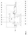
- Fig. 1 to 3 show a mounting rail 10 and a housing 12 according to the invention for electrical installation equipment.
- Such housing 12 are used in particular for low-voltage switchgear such as circuit breakers, residual current circuit breaker, fault current signal generator, load switch and relay as well as additional modules for the aforementioned installation equipment.
- the housing 12 such installation devices may have different housing shapes depending on the function as circuit breaker or residual current circuit breaker. However, the housing rear sides, on which the housings of the installation devices are mounted on the common mounting rail, have an at least similar shape, despite the different housing shapes.
- the region of the housing, which in each case has a similar design, is in particular in FIG Fig. 1 to 3 shown. Similar housings 12 may in particular have a different length, wherein the longitudinal direction L of the housing 12, if this is latched onto the mounting rail 10, extends in the longitudinal direction L of the mounting rail 10.
- a plurality of housings 12 are lined up in the longitudinal direction L of the mounting rail 10 and secured thereto by means of a locking element 14 described below.
- the mounting rail 10 which is also referred to as DIN rail and is standardized, for example, in the standard DIN EN 60715, has a flat mounting plate 16, by means of which the mounting rail 10, for example, in a fuse box or the like is attached.
- this mounting plate 16 is perpendicular to the plane of the drawing. From this mounting plate 16 are laterally from two mounting arms 18, at the free ends of each a mounting plate 20, 20 'is integrally formed. The two facing away from the mounting plate 16 surfaces of the mounting plates 20, 20 'together form a counter-abutment surface 22 for a housing 12 formed on the stop surface 24.
- the angled relative to the counter-stop surface 20, 20 'by the taper surface forms a first counter-clamping surface 26, which acts to fix the housing 12 to the support rail 10 with a first clamping surface 28 on the locking element 14 together.
- the counter clamping surface 26 may alternatively be aligned parallel to the counter stop surface 22.
- the support rail 10 is formed symmetrically and thus has per attachment plate 20, 20 ', a first counter-clamping surface 26.
- the housing 12 is not formed symmetrically, would also be a non-symmetrical design of the support rail 10 is possible, which has only a first counter-clamping surface 26 according to the above description.
- the stop surface 24 of the housing 12 has a width which corresponds to the distance between the two outer edges of the two attachment plates 20, 20 '.
- a rigidly formed holding hook 30 adjoins the stop surface 24, which is intended to engage behind one of the two fastening plates 20 in a known manner.
- a smaller, nose-like projection 32 abuts against the retaining hook 30. Together with the retaining hook 30 of the nose-like projection 32 laterally - in the direction of the width B - the stop surface 24 and holds in the direction of the width B, the housing 12 immovably on the support rail 10th
- the displaceably formed locking element 14 is arranged on the outside of the housing 12.
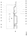
- This in Fig. 1 to 5 shown locking element 14 is held transversely to the longitudinal direction L or in the direction of the ready B of the housing from a mounting position into a fixing position back and forth on the housing, wherein the housing 12 for this purpose guide grooves 34 (in Fig. 1 and 2 one of the guide grooves is visible) and the locking element 14 has corresponding, in the guide grooves 34 engaging guide elements 36 (see Fig. 4, 5 ).
- the in the direction of movement of the locking element 14 of the stop surface 24 facing end portion 38 of the locking member 14 has a longitudinal direction L of the housing 12 extending groove 40, one flank of the first clamping surface 28 and the other edge forms a second clamping surface 44.
- the two flanks are connected to each other via the groove bottom.
- the first clamping surface 28 defines a region of the locking element 14, which in the fixing position of the Locking element 14, the counter-stop surface 22 of the support rail 10 engages behind.
- the in Fig. 1 illustrated embodiment of the support rail 10 acts in the fixing position of the locking element 14, the first clamping surface 28 with the first mating clamping surface 26 of the support rail 10 together.
- the 2 illustrated embodiment of the support rail 10 acts in the fixing position of the locking element 14, the first clamping surface 28 at least with the edge of the first counter-clamping surface 26 together.
- the second clamping surface 44 defines a hook-like region 46 of the locking element 14, which engages behind the stop surface 24 of the housing 12 in the fixing position of the locking element 14.
- the housing 12 has a recess 48 into which the hook-like region 46 of the locking element 14 engages.
- the recess 48 is open on both sides in the longitudinal direction L.
- the recess 48 and the hook-like portion 46 are formed such that the hook-like portion 46 during the displacement of the locking element 14 between the mounting position and the fixing position in this recess 48 is movable back and forth.
- the recess 48 is formed such that the hook-like portion 46 when placed on the housing 12 or when mounting the locking element 14 on the housing 12 can be inserted into the recess 48.
- the hook-like region 46 of the locking element 14 engages behind the nose-like projection 32 and the stop surface 24 of the housing 12 at least partially and the second clamping surface 44 of the locking element 14 cooperates with a second counter clamping surface 50 formed on the housing 12.
- the second counter clamping surface 50 on the housing 12 delimits the recess 48 in the direction of the stop surface 24 and is arranged parallel to the stop surface 24.
- the nose-like projection 32 is formed such that the nose-like projection 32 in the fixing position of the locking element 14 does not touch this, that is, in the fixing position of the locking element 14, the nose-like projection 32 is spaced from the first clamping surface 28.
- first clamping surface 28 and the second clamping surface 44 are arranged opposite in the direction of the holding force K.
- the locking element 14 only has to absorb a very small torque.
- the locking element 14 is held by means of guide elements 36 in guide grooves 34 on the housing 12 and guided to move from the mounting position to the fixing position on the housing 12.
- the guide elements 36 are formed on two side frame legs 60, which in turn at the end portion 38, which has the groove 40 with the first clamping surface 28 and the second clamping surface 44, are integrally formed.
- the two frame legs 60 are connected to each other via an end leg 64.
- the locking element 14 can be actuated either by hand or by means of a tool such as a screwdriver, pliers or a specially developed special tool, that is moved from the mounting position into the fixing position or from the fixing position into the mounting position.
- a tool such as a screwdriver, pliers or a specially developed special tool
- the locking element a Spring element 66, which is formed in the present example of the same material as the locking element 14.
- this spring element 66 may also consist of a separate part and be formed of a different plastic or metal.
- the spring element 66 is formed on the end portion 38 and extends in a known manner in a wave form from the end portion 38 in the direction of the end leg 64.
- the spring element 66 serves to exert a force on the locking element 14, so that the locking element 14 is urged into the fixing position becomes.
- the free end of the spring element 66 is supported on the housing 12.
- the length of the locking element in the longitudinal direction L of the housing 12 is the same size as the length of the housing 12, so that the locking element 14 is not in the longitudinal direction L on the housing 12 before.
- the locking element in the longitudinal direction L of the housing may be formed narrower than the housing.
Abstract
Description
Die Erfindung bezieht sich auf das Gebiet der Gehäuse für elektrische Installationsgeräte, insbesondere der Gehäuse für Niederspannungsschaltgeräte bis 1000 V wie Reiheneinbaugeräte, Leitungsschutzschalter, Fehlerstromschutzschalter, Relais, Ein- und Ausschalter, Signalapparate oder Steuerschalter. Die Erfindung bezieht sich insbesondere auf ein Gehäuse gemäss dem Oberbegriff von Anspruch 1.The invention relates to the field of housings for electrical installation equipment, in particular the housing for low-voltage switchgear up to 1000 V as modular devices, circuit breakers, residual current circuit breakers, relays, on and off switches, signaling devices or control switches. The invention particularly relates to a housing according to the preamble of claim 1.
Aus
Die Aufgabe der Erfindung besteht darin, ein Gehäuse mit einem verbesserten Verriegelungselement zu schaffen.The object of the invention is to provide a housing with an improved locking element.
Die obige Aufgabe wird erfindungsgemäss durch ein Gehäuse mit den Merkmalen des Anspruchs 1 gelöst.
Erfindungsgemäss weist das Gehäuse ein Verriegelungselement auf, an welchem die erste Klemmfläche und die zweite Klemmfläche einander gegenüberliegend angeordnet sind. Dadurch wird erreicht, dass nahezu kein Drehmoment auf das Verriegelungselement übertragen wird, beziehungsweise von diesem aufgenommen werden muss. Dadurch ist es möglich, die Führungselemente, mittels welchen das Verriegelungselement am Gehäuse gehalten ist, im Vergleich zum Stand der Technik weniger stark auszubilden.
Bevorzugte Ausführungsformen und Vorteile gehen aus den abhängigen Patentansprüchen und den Figuren hervor.The above object is achieved according to the invention by a housing having the features of claim 1.
According to the invention, the housing has a locking element, on which the first clamping surface and the second clamping surface are arranged opposite one another. This ensures that almost no torque is transmitted to the locking element, or must be absorbed by this. This makes it possible, the guide elements, by means of which the locking element is held on the housing, less pronounced form compared to the prior art.
Preferred embodiments and advantages will become apparent from the dependent claims and the figures.
Im folgenden wird der Erfindungsgegenstand anhand eines bevorzugten Ausführungsbeispielen näher erläutert, welche in den beiliegenden Figuren dargestellt sind. Es zeigen rein schematisch:
- Fig. 1
- in Ansicht das erfindungsgemässe Gehäuse aufgerastet auf einer geschnitten gezeigten Tragschiene gemäss einer ersten Ausführungsform, wobei ein Verriegelungselement in seiner Fixierstellung gezeigt ist;
- Fig. 2
- in Ansicht das erfindungsgemässe Gehäuse aufgerastet auf einer geschnitten gezeigten Tragschiene gemäss einer zweiten Ausführungsform, wobei ein Verriegelungselement in seiner Fixierstellung gezeigt ist;
- Fig. 3
- in Ansicht das erfindungsgemässe Gehäuse in Anlage an die geschnitten gezeigten Tragschiene, wobei das Verriegelungselement in seiner Montagestellung gezeigt ist;
- Fig. 4
- in Schnittdarstellung das Verriegelungselement; und
- Fig. 5
- das Verriegelungselement in perspektivischer Darstellung.
- Fig. 1
- in view of the inventive housing snapped onto a support rail shown cut according to a first embodiment, wherein a locking element is shown in its fixing position;
- Fig. 2
- in view of the inventive housing snapped onto a support rail shown in section cut according to a second embodiment, wherein a locking element is shown in its fixing position;
- Fig. 3
- in view of the inventive housing in abutment with the cut support rail shown, wherein the locking element is shown in its mounting position;
- Fig. 4
- in sectional view the locking element; and
- Fig. 5
- the locking element in perspective view.
Die Gehäuse 12 derartiger Installationsgeräte können je nach Funktion wie Leitungsschutzschalter oder Fehlerstromschutzschalter unterschiedliche Gehäuseformen aufweisen. Die Gehäuserückseiten, an welchen die Gehäuse der Installationsgeräte auf der gemeinsamen Tragschiene montiert werden, weisen jedoch trotz unterschiedlicher Gehäuseform eine zumindest ähnliche Form auf. Derjenige Bereich der Gehäuse, welcher jeweils ähnlich ausgebildet ist, ist insbesondere in
Die Tragschiene 10, welche auch als Hutschiene bezeichnet wird und beispielsweise in der Norm DIN EN 60715 genormt ist, weist eine flächige Montageplatte 16 auf, mittels welcher die Tragschiene 10 beispielsweise in einem Sicherungskasten oder dergleichen befestigt wird. In
Die Anschlagfläche 24 des Gehäuses 12 weist eine Breite auf, die dem Abstand der beiden aussen liegenden Kanten der beiden Befestigungsplatten 20, 20' entspricht. In Richtung der Breite B, rechtwinklig zur Längsrichtung L, grenzt einerseits ein starr ausgebildeter Haltehaken 30 an die Anschlagfläche 24 an, der dazu bestimmt ist, die eine der beiden Befestigungsplatten 20 in bekannter Art und Weise zu hintergreift. Andererseits grenzt an die Anschlagfläche 24 ein im Vergleich zum Haltehaken 30 kleiner, nasenartiger Vorsprung 32 an. Zusammen mit dem Haltehaken 30 begrenzt der nasenartige Vorsprung 32 seitlich - in Richtung der Breite B - die Anschlagfläche 24 und hält in Richtung der Breite B das Gehäuse 12 unverschiebbar an der Tragschiene 10.The
Um das Gehäuse 12 fest an der Tragschiene 10 zu fixieren, ist aussen am Gehäuse 12 das verschiebbar ausgebildete Verriegelungselement 14 angeordnet. Das in
Der in Bewegungsrichtung des Verriegelungselements 14 der Anschlagfläche 24 zugewandte Endbereich 38 des Verriegelungselements 14 weist eine in Längsrichtung L des Gehäuses 12 verlaufende Nut 40 auf, deren eine Flanke die erste Klemmfläche 28 und deren andere Flanke eine zweite Klemmfläche 44 bildet. Die beiden Flanken sind über den Nutboden miteinander Verbunden. Die erste Klemmfläche 28 begrenzt einen Bereich des Verriegelungselements 14, der in der Fixierstellung des Verriegelungselements 14 die Gegenanschlagfläche 22 der Tragschiene 10 hintergreift. In der in
In der Fixierstellung des Verriegelungselements 14 hintergreift der hakenartige Bereich 46 des Verriegelungselements 14 den nasenartigen Vorsprung 32 und die Anschlagfläche 24 des Gehäuses 12 zumindest teilweise und die zweite Klemmfläche 44 des Verriegelungselements 14 wirkt mit einer am Gehäuse 12 ausgebildeten zweiten Gegenklemmfläche 50 zusammen. Die zweite Gegenklemmfläche 50 am Gehäuse 12 begrenzt die Ausnehmung 48 in Richtung der Anschlagfläche 24 und ist parallel zur Anschlagfläche 24 angeordnet.In the fixing position of the locking
Durch das Zusammenwirken der ersten Klemmfläche 28 des Verriegelungselements 14 mit der ersten Gegenklemmfläche 26 an der Tragschiene 10 und durch das Zusammenwirken der zweiten Klemmfläche 44 des Verriegelungselements 14 mit der zweiten Gegenklemmfläche 50 am Gehäuse 12 wird die Anschlagfläche 24 des Gehäuses 12 fest an die Gegenanschlagfläche 22 an der Tragschiene 10 gepresst und folglich das Gehäuse 12 fest an der Tragschiene 10 fixiert. Folglich wird durch den Endbereich 38 des Verriegelungselements 14, der die Nut 40 aufweist, eine Haltekraft erzeugt, welche die Anschlagfläche 24 fest an die Gegenanschlagfläche 22 drückt. Die Richtung K dieser Haltekraft steht im Wesentlichen senkrecht auf der Anschlagsfläche 24 und der Gegenanschlagfläche 22. Damit die Haltekraft vollständig zum Zusammenpressen der Anschlagfläche 24 und der Gegenanschlagfläche 22 genutzt wird, ist der nasenartige Vorsprung 32 derart ausgebildet, dass der nasenartige Vorsprung 32 in der Fixierposition des Verriegelungselements 14 dieses nicht berührt, das heisst, dass in der Fixierposition des Verriegelungselements 14 der nasenartige Vorsprung 32 von der ersten Klemmfläche 28 beabstandet ist.By the interaction of the
Besonders vorteilhaft ist die Anordnung der ersten Klemmfläche 28 und der zweiten Klemmfläche 44 als Flanken der Nut 40, da dadurch die Kraftübertragung in einem relativ kleinen Bereich am Verriegelungselement 14 erfolgt. Weiter sind die erste Klemmfläche 28 und die zweite Klemmfläche 44 in Richtung der Haltekraft K gegenüberliegend angeordnet. Dies führt dazu, dass das Verriegelungselement 14 nur ein sehr kleines Drehmoment aufnehmen muss. Folglich kann des Verriegelungselement 14 mit Ausnahme des Endbereichs 38, an welchem die Nut 40 mit der ersten Klemmfläche 28 und der zweiten Klemmfläche 44 ausgebildet ist, im Vergleich zum Stand der Technik fein ausgebildet werden, da die übrigen Bereiche des Verriegelungselements 14 wenig durch die Kraft zum Halten des Gehäuses 12 an der Tragschiene 10 belastet werden.Particularly advantageous is the arrangement of the
Wie oben bereits ausgeführt, ist das Verriegelungselement 14 mittels Führungselementen 36 in Führungsnuten 34 am Gehäuse 12 gehalten und zum Verschieben von der Montagestellung in die Fixierstellung am Gehäuse 12 geführt. Wie in
- 1010
- Tragschienerail
- 1212
- Gehäusecasing
- 1414
- Verriegelungselementlocking element
- 1616
- Montageplattemounting plate
- 1818
- Befestigungsarmemounting arms
- 20, 20'20, 20 '
- Befestigungsplattemounting plate
- 2222
- Gegenanschlagfläche an der TragschieneCounter stop surface on the mounting rail
- 2424
- Anschlagfläche am GehäuseStop surface on the housing
- 2626
- erste Gegenklemmfläche an der Tragschienefirst counter clamping surface on the mounting rail
- 2828
- erste Klemmfläche am Verriegelungselementfirst clamping surface on the locking element
- 3030
- Haltehakenretaining hook
- 3232
- Nasenartiger VorsprungNose-like projection
- 3434
- Führungsnutenguide
- 3636
- Führungselementeguide elements
- 3838
- Endbereichend
- 4040
- Nutgroove
- 4444
- zweite Klemmfläche am Verriegelungselementsecond clamping surface on the locking element
- 4646
- Hakenartiger BereichHook-like area
- 4848
- Ausnehmungrecess
- 5050
- zweite Gegenklemmfläche am Gehäusesecond counter clamping surface on the housing
- 6060
- Rahmenschenkelframe legs
- 6262
- Endbereichend
- 6464
- Endschenkelend leg
- 6666
- Federelementspring element
- LL
- Längsrichtunglongitudinal direction
- BB
- Richtung der BreiteDirection of the width
- KK
- Haltekraftholding force
Claims (10)
dass das Verriegelungselement (14) eine zweite Klemmfläche (44) aufweist, welche die Anschlagfläche (24) des Gehäuses (12) hintergreift.Housing for an electrical installation device which can be latched onto a mounting rail (10) and rests with its stop surface (24) in a state latched onto the mounting rail (10) against a counter-abutment surface (22) of the mounting rail (10), wherein 12) on the support rail (10), a locking element (14) can be moved from a mounting position to a fixing position, and the locking element (14) has a first clamping surface (28) for fixing the housing (12) on the support rail (10 ) engages behind the counter stop surface (22) of the support rail (10), characterized in that
in that the locking element (14) has a second clamping surface (44) which engages behind the stop surface (24) of the housing (12).
Priority Applications (4)
| Application Number | Priority Date | Filing Date | Title |
|---|---|---|---|
| EP08158753A EP2139085B1 (en) | 2008-06-23 | 2008-06-23 | Casing with lock element |
| AT08158753T ATE519259T1 (en) | 2008-06-23 | 2008-06-23 | HOUSING WITH LOCKING ELEMENT |
| ES08158753T ES2370669T3 (en) | 2008-06-23 | 2008-06-23 | HOUSING WITH LOCK ELEMENT. |
| CN200920156562XU CN201584659U (en) | 2008-06-23 | 2009-06-23 | Shell body for electric installation device |
Applications Claiming Priority (1)
| Application Number | Priority Date | Filing Date | Title |
|---|---|---|---|
| EP08158753A EP2139085B1 (en) | 2008-06-23 | 2008-06-23 | Casing with lock element |
Publications (2)
| Publication Number | Publication Date |
|---|---|
| EP2139085A1 true EP2139085A1 (en) | 2009-12-30 |
| EP2139085B1 EP2139085B1 (en) | 2011-08-03 |
Family
ID=40134956
Family Applications (1)
| Application Number | Title | Priority Date | Filing Date |
|---|---|---|---|
| EP08158753A Not-in-force EP2139085B1 (en) | 2008-06-23 | 2008-06-23 | Casing with lock element |
Country Status (4)
| Country | Link |
|---|---|
| EP (1) | EP2139085B1 (en) |
| CN (1) | CN201584659U (en) |
| AT (1) | ATE519259T1 (en) |
| ES (1) | ES2370669T3 (en) |
Families Citing this family (2)
| Publication number | Priority date | Publication date | Assignee | Title |
|---|---|---|---|---|
| US8226433B1 (en) * | 2011-03-23 | 2012-07-24 | Phoenix Contact Development & Manufacturing, Inc. | Latch assembly for mounting power supply base for a process fieldbus on a DIN rail and method |
| CN104167310B (en) * | 2014-08-20 | 2016-03-02 | 加西亚电子电器有限公司 | A kind of snap device of low-voltage electrical apparatus and miniature circuit breaker |
Citations (4)
| Publication number | Priority date | Publication date | Assignee | Title |
|---|---|---|---|---|
| DE3513762A1 (en) | 1985-04-17 | 1986-10-23 | Brown, Boveri & Cie Ag, 6800 Mannheim | Electrical insulation apparatus which can be latched onto a supporting rail |
| EP0785607A2 (en) | 1990-08-21 | 1997-07-23 | Crabtree Electrical Industries Limited | Improvements relating to the mounting of circuit breakers |
| DE10211903A1 (en) | 2002-03-18 | 2003-10-02 | Eti Elektroelement Dd | Serially fitted electric appliance for installation distributor etc. which can be mounted on support rail, has engagement slider contg. swivel and lock mechanism permitting its arresting in open position |
| DE10220821B3 (en) | 2002-05-10 | 2004-02-26 | Geyer Ag | Quick-fixing for serial electrical installation device, comprises one-piece snap-fit latch fitted to holder at base of electrical installation device for sliding to and from collector rail |
-
2008
- 2008-06-23 ES ES08158753T patent/ES2370669T3/en active Active
- 2008-06-23 AT AT08158753T patent/ATE519259T1/en active
- 2008-06-23 EP EP08158753A patent/EP2139085B1/en not_active Not-in-force
-
2009
- 2009-06-23 CN CN200920156562XU patent/CN201584659U/en not_active Expired - Fee Related
Patent Citations (4)
| Publication number | Priority date | Publication date | Assignee | Title |
|---|---|---|---|---|
| DE3513762A1 (en) | 1985-04-17 | 1986-10-23 | Brown, Boveri & Cie Ag, 6800 Mannheim | Electrical insulation apparatus which can be latched onto a supporting rail |
| EP0785607A2 (en) | 1990-08-21 | 1997-07-23 | Crabtree Electrical Industries Limited | Improvements relating to the mounting of circuit breakers |
| DE10211903A1 (en) | 2002-03-18 | 2003-10-02 | Eti Elektroelement Dd | Serially fitted electric appliance for installation distributor etc. which can be mounted on support rail, has engagement slider contg. swivel and lock mechanism permitting its arresting in open position |
| DE10220821B3 (en) | 2002-05-10 | 2004-02-26 | Geyer Ag | Quick-fixing for serial electrical installation device, comprises one-piece snap-fit latch fitted to holder at base of electrical installation device for sliding to and from collector rail |
Also Published As
| Publication number | Publication date |
|---|---|
| CN201584659U (en) | 2010-09-15 |
| ES2370669T3 (en) | 2011-12-21 |
| EP2139085B1 (en) | 2011-08-03 |
| ATE519259T1 (en) | 2011-08-15 |
Similar Documents
| Publication | Publication Date | Title |
|---|---|---|
| EP3639334B1 (en) | Fixation to a support rail | |
| EP2839544B1 (en) | Test terminal block | |
| DE202015106673U1 (en) | Bayable component | |
| DE102013111551B3 (en) | DIN rail enclosure | |
| WO2013020769A1 (en) | Housing, in particular a connection terminal or the like, comprising a contour-guided actuating element | |
| EP3454422A1 (en) | Cable connection terminal | |
| DE102014108090B3 (en) | Adapter system with an adapter for busbars and an adapter connection module | |
| EP1254495B1 (en) | Apparatus for fixing switching devices on mounting rails | |
| EP2033266B1 (en) | Cable connection clamp | |
| EP2139085B1 (en) | Casing with lock element | |
| DE102010041197B4 (en) | DIN rail and electrical distribution manifold | |
| EP2037550B1 (en) | Protection against contact for a rail | |
| DE102011087209B4 (en) | Electrical installation equipment | |
| DE102011110642B4 (en) | hardware assembly | |
| EP2211599A1 (en) | Assembly and assembly holder | |
| DE102010033112B4 (en) | Electrical installation device | |
| EP1050090B1 (en) | Connecting element | |
| EP2124306A2 (en) | Electrical switching unit for an electrical switching assembly, in particular for medium voltage | |
| WO1998025284A1 (en) | Safety switch | |
| EP1460721B1 (en) | Electric appliance with quick fastening means | |
| WO2021005138A1 (en) | Measuring instrument for installation in a control panel | |
| DE102007003674B3 (en) | Bearing block for e.g. power switch, has axle with half shell section positioned such that switching piece is pivoted during engagement of force device, where piece is switched-on, switched-off and released in three positions | |
| DE10032518C1 (en) | Multi-stage electrical switch has switch elements operated in succession by movement of manual operating element via respective switch operating elements | |
| DE102005011403B4 (en) | Slot for a low-voltage switchgear | |
| EP1028488B1 (en) | Connecting terminal for an electrical apparatus |
Legal Events
| Date | Code | Title | Description |
|---|---|---|---|
| PUAI | Public reference made under article 153(3) epc to a published international application that has entered the european phase |
Free format text: ORIGINAL CODE: 0009012 |
|
| AK | Designated contracting states |
Kind code of ref document: A1 Designated state(s): AT BE BG CH CY CZ DE DK EE ES FI FR GB GR HR HU IE IS IT LI LT LU LV MC MT NL NO PL PT RO SE SI SK TR |
|
| AX | Request for extension of the european patent |
Extension state: AL BA MK RS |
|
| 17P | Request for examination filed |
Effective date: 20100609 |
|
| AKX | Designation fees paid |
Designated state(s): AT BE BG CH CY CZ DE DK EE ES FI FR GB GR HR HU IE IS IT LI LT LU LV MC MT NL NO PL PT RO SE SI SK TR |
|
| 17Q | First examination report despatched |
Effective date: 20100823 |
|
| GRAP | Despatch of communication of intention to grant a patent |
Free format text: ORIGINAL CODE: EPIDOSNIGR1 |
|
| GRAS | Grant fee paid |
Free format text: ORIGINAL CODE: EPIDOSNIGR3 |
|
| GRAA | (expected) grant |
Free format text: ORIGINAL CODE: 0009210 |
|
| AK | Designated contracting states |
Kind code of ref document: B1 Designated state(s): AT BE BG CH CY CZ DE DK EE ES FI FR GB GR HR HU IE IS IT LI LT LU LV MC MT NL NO PL PT RO SE SI SK TR |
|
| REG | Reference to a national code |
Ref country code: GB Ref legal event code: FG4D Free format text: NOT ENGLISH |
|
| REG | Reference to a national code |
Ref country code: CH Ref legal event code: EP |
|
| REG | Reference to a national code |
Ref country code: IE Ref legal event code: FG4D Free format text: LANGUAGE OF EP DOCUMENT: GERMAN |
|
| REG | Reference to a national code |
Ref country code: DE Ref legal event code: R096 Ref document number: 502008004372 Country of ref document: DE Effective date: 20110929 |
|
| REG | Reference to a national code |
Ref country code: NL Ref legal event code: VDEP Effective date: 20110803 |
|
| REG | Reference to a national code |
Ref country code: ES Ref legal event code: FG2A Ref document number: 2370669 Country of ref document: ES Kind code of ref document: T3 Effective date: 20111221 |
|
| LTIE | Lt: invalidation of european patent or patent extension |
Effective date: 20110803 |
|
| PG25 | Lapsed in a contracting state [announced via postgrant information from national office to epo] |
Ref country code: IS Free format text: LAPSE BECAUSE OF FAILURE TO SUBMIT A TRANSLATION OF THE DESCRIPTION OR TO PAY THE FEE WITHIN THE PRESCRIBED TIME-LIMIT Effective date: 20111203 Ref country code: NL Free format text: LAPSE BECAUSE OF FAILURE TO SUBMIT A TRANSLATION OF THE DESCRIPTION OR TO PAY THE FEE WITHIN THE PRESCRIBED TIME-LIMIT Effective date: 20110803 Ref country code: SE Free format text: LAPSE BECAUSE OF FAILURE TO SUBMIT A TRANSLATION OF THE DESCRIPTION OR TO PAY THE FEE WITHIN THE PRESCRIBED TIME-LIMIT Effective date: 20110803 Ref country code: NO Free format text: LAPSE BECAUSE OF FAILURE TO SUBMIT A TRANSLATION OF THE DESCRIPTION OR TO PAY THE FEE WITHIN THE PRESCRIBED TIME-LIMIT Effective date: 20111103 Ref country code: FI Free format text: LAPSE BECAUSE OF FAILURE TO SUBMIT A TRANSLATION OF THE DESCRIPTION OR TO PAY THE FEE WITHIN THE PRESCRIBED TIME-LIMIT Effective date: 20110803 Ref country code: LT Free format text: LAPSE BECAUSE OF FAILURE TO SUBMIT A TRANSLATION OF THE DESCRIPTION OR TO PAY THE FEE WITHIN THE PRESCRIBED TIME-LIMIT Effective date: 20110803 Ref country code: PT Free format text: LAPSE BECAUSE OF FAILURE TO SUBMIT A TRANSLATION OF THE DESCRIPTION OR TO PAY THE FEE WITHIN THE PRESCRIBED TIME-LIMIT Effective date: 20111205 Ref country code: HR Free format text: LAPSE BECAUSE OF FAILURE TO SUBMIT A TRANSLATION OF THE DESCRIPTION OR TO PAY THE FEE WITHIN THE PRESCRIBED TIME-LIMIT Effective date: 20110803 |
|
| PG25 | Lapsed in a contracting state [announced via postgrant information from national office to epo] |
Ref country code: LV Free format text: LAPSE BECAUSE OF FAILURE TO SUBMIT A TRANSLATION OF THE DESCRIPTION OR TO PAY THE FEE WITHIN THE PRESCRIBED TIME-LIMIT Effective date: 20110803 Ref country code: PL Free format text: LAPSE BECAUSE OF FAILURE TO SUBMIT A TRANSLATION OF THE DESCRIPTION OR TO PAY THE FEE WITHIN THE PRESCRIBED TIME-LIMIT Effective date: 20110803 Ref country code: CY Free format text: LAPSE BECAUSE OF FAILURE TO SUBMIT A TRANSLATION OF THE DESCRIPTION OR TO PAY THE FEE WITHIN THE PRESCRIBED TIME-LIMIT Effective date: 20110803 Ref country code: SI Free format text: LAPSE BECAUSE OF FAILURE TO SUBMIT A TRANSLATION OF THE DESCRIPTION OR TO PAY THE FEE WITHIN THE PRESCRIBED TIME-LIMIT Effective date: 20110803 Ref country code: GR Free format text: LAPSE BECAUSE OF FAILURE TO SUBMIT A TRANSLATION OF THE DESCRIPTION OR TO PAY THE FEE WITHIN THE PRESCRIBED TIME-LIMIT Effective date: 20111104 |
|
| REG | Reference to a national code |
Ref country code: IE Ref legal event code: FD4D |
|
| PG25 | Lapsed in a contracting state [announced via postgrant information from national office to epo] |
Ref country code: CZ Free format text: LAPSE BECAUSE OF FAILURE TO SUBMIT A TRANSLATION OF THE DESCRIPTION OR TO PAY THE FEE WITHIN THE PRESCRIBED TIME-LIMIT Effective date: 20110803 Ref country code: SK Free format text: LAPSE BECAUSE OF FAILURE TO SUBMIT A TRANSLATION OF THE DESCRIPTION OR TO PAY THE FEE WITHIN THE PRESCRIBED TIME-LIMIT Effective date: 20110803 Ref country code: IE Free format text: LAPSE BECAUSE OF FAILURE TO SUBMIT A TRANSLATION OF THE DESCRIPTION OR TO PAY THE FEE WITHIN THE PRESCRIBED TIME-LIMIT Effective date: 20110803 |
|
| PG25 | Lapsed in a contracting state [announced via postgrant information from national office to epo] |
Ref country code: RO Free format text: LAPSE BECAUSE OF FAILURE TO SUBMIT A TRANSLATION OF THE DESCRIPTION OR TO PAY THE FEE WITHIN THE PRESCRIBED TIME-LIMIT Effective date: 20110803 Ref country code: EE Free format text: LAPSE BECAUSE OF FAILURE TO SUBMIT A TRANSLATION OF THE DESCRIPTION OR TO PAY THE FEE WITHIN THE PRESCRIBED TIME-LIMIT Effective date: 20110803 |
|
| PLBE | No opposition filed within time limit |
Free format text: ORIGINAL CODE: 0009261 |
|
| STAA | Information on the status of an ep patent application or granted ep patent |
Free format text: STATUS: NO OPPOSITION FILED WITHIN TIME LIMIT |
|
| PG25 | Lapsed in a contracting state [announced via postgrant information from national office to epo] |
Ref country code: DK Free format text: LAPSE BECAUSE OF FAILURE TO SUBMIT A TRANSLATION OF THE DESCRIPTION OR TO PAY THE FEE WITHIN THE PRESCRIBED TIME-LIMIT Effective date: 20110803 |
|
| 26N | No opposition filed |
Effective date: 20120504 |
|
| REG | Reference to a national code |
Ref country code: DE Ref legal event code: R097 Ref document number: 502008004372 Country of ref document: DE Effective date: 20120504 |
|
| BERE | Be: lapsed |
Owner name: ABB SCHWEIZ A.G. Effective date: 20120630 |
|
| PG25 | Lapsed in a contracting state [announced via postgrant information from national office to epo] |
Ref country code: MC Free format text: LAPSE BECAUSE OF NON-PAYMENT OF DUE FEES Effective date: 20120630 |
|
| REG | Reference to a national code |
Ref country code: CH Ref legal event code: PL |
|
| REG | Reference to a national code |
Ref country code: CH Ref legal event code: PL |
|
| PG25 | Lapsed in a contracting state [announced via postgrant information from national office to epo] |
Ref country code: LI Free format text: LAPSE BECAUSE OF NON-PAYMENT OF DUE FEES Effective date: 20120630 Ref country code: CH Free format text: LAPSE BECAUSE OF NON-PAYMENT OF DUE FEES Effective date: 20120630 Ref country code: BE Free format text: LAPSE BECAUSE OF NON-PAYMENT OF DUE FEES Effective date: 20120630 |
|
| PG25 | Lapsed in a contracting state [announced via postgrant information from national office to epo] |
Ref country code: BG Free format text: LAPSE BECAUSE OF FAILURE TO SUBMIT A TRANSLATION OF THE DESCRIPTION OR TO PAY THE FEE WITHIN THE PRESCRIBED TIME-LIMIT Effective date: 20111103 |
|
| PG25 | Lapsed in a contracting state [announced via postgrant information from national office to epo] |
Ref country code: MT Free format text: LAPSE BECAUSE OF FAILURE TO SUBMIT A TRANSLATION OF THE DESCRIPTION OR TO PAY THE FEE WITHIN THE PRESCRIBED TIME-LIMIT Effective date: 20110803 |
|
| PG25 | Lapsed in a contracting state [announced via postgrant information from national office to epo] |
Ref country code: TR Free format text: LAPSE BECAUSE OF FAILURE TO SUBMIT A TRANSLATION OF THE DESCRIPTION OR TO PAY THE FEE WITHIN THE PRESCRIBED TIME-LIMIT Effective date: 20110803 |
|
| PG25 | Lapsed in a contracting state [announced via postgrant information from national office to epo] |
Ref country code: LU Free format text: LAPSE BECAUSE OF NON-PAYMENT OF DUE FEES Effective date: 20120623 |
|
| PG25 | Lapsed in a contracting state [announced via postgrant information from national office to epo] |
Ref country code: HU Free format text: LAPSE BECAUSE OF FAILURE TO SUBMIT A TRANSLATION OF THE DESCRIPTION OR TO PAY THE FEE WITHIN THE PRESCRIBED TIME-LIMIT Effective date: 20080623 |
|
| REG | Reference to a national code |
Ref country code: AT Ref legal event code: MM01 Ref document number: 519259 Country of ref document: AT Kind code of ref document: T Effective date: 20130623 |
|
| PG25 | Lapsed in a contracting state [announced via postgrant information from national office to epo] |
Ref country code: AT Free format text: LAPSE BECAUSE OF NON-PAYMENT OF DUE FEES Effective date: 20130623 |
|
| REG | Reference to a national code |
Ref country code: FR Ref legal event code: PLFP Year of fee payment: 8 |
|
| PGFP | Annual fee paid to national office [announced via postgrant information from national office to epo] |
Ref country code: DE Payment date: 20150619 Year of fee payment: 8 Ref country code: ES Payment date: 20150626 Year of fee payment: 8 Ref country code: GB Payment date: 20150618 Year of fee payment: 8 |
|
| PGFP | Annual fee paid to national office [announced via postgrant information from national office to epo] |
Ref country code: IT Payment date: 20150622 Year of fee payment: 8 Ref country code: FR Payment date: 20150619 Year of fee payment: 8 |
|
| REG | Reference to a national code |
Ref country code: DE Ref legal event code: R119 Ref document number: 502008004372 Country of ref document: DE |
|
| GBPC | Gb: european patent ceased through non-payment of renewal fee |
Effective date: 20160623 |
|
| REG | Reference to a national code |
Ref country code: FR Ref legal event code: ST Effective date: 20170228 |
|
| PG25 | Lapsed in a contracting state [announced via postgrant information from national office to epo] |
Ref country code: FR Free format text: LAPSE BECAUSE OF NON-PAYMENT OF DUE FEES Effective date: 20160630 Ref country code: DE Free format text: LAPSE BECAUSE OF NON-PAYMENT OF DUE FEES Effective date: 20170103 |
|
| PG25 | Lapsed in a contracting state [announced via postgrant information from national office to epo] |
Ref country code: GB Free format text: LAPSE BECAUSE OF NON-PAYMENT OF DUE FEES Effective date: 20160623 |
|
| PG25 | Lapsed in a contracting state [announced via postgrant information from national office to epo] |
Ref country code: IT Free format text: LAPSE BECAUSE OF NON-PAYMENT OF DUE FEES Effective date: 20160623 |
|
| PG25 | Lapsed in a contracting state [announced via postgrant information from national office to epo] |
Ref country code: ES Free format text: LAPSE BECAUSE OF NON-PAYMENT OF DUE FEES Effective date: 20160624 |
|
| REG | Reference to a national code |
Ref country code: ES Ref legal event code: FD2A Effective date: 20181203 |