EP2139043A2 - Photovoltaic shingles for roofing and method for connecting the shingles - Google Patents
Photovoltaic shingles for roofing and method for connecting the shingles Download PDFInfo
- Publication number
- EP2139043A2 EP2139043A2 EP09163093A EP09163093A EP2139043A2 EP 2139043 A2 EP2139043 A2 EP 2139043A2 EP 09163093 A EP09163093 A EP 09163093A EP 09163093 A EP09163093 A EP 09163093A EP 2139043 A2 EP2139043 A2 EP 2139043A2
- Authority
- EP
- European Patent Office
- Prior art keywords
- shingle
- shingles
- connector
- row
- roof
- Prior art date
- Legal status (The legal status is an assumption and is not a legal conclusion. Google has not performed a legal analysis and makes no representation as to the accuracy of the status listed.)
- Withdrawn
Links
- 238000000034 method Methods 0.000 title claims description 15
- 230000013011 mating Effects 0.000 claims abstract description 15
- 230000008878 coupling Effects 0.000 claims description 19
- 238000010168 coupling process Methods 0.000 claims description 19
- 238000005859 coupling reaction Methods 0.000 claims description 19
- 239000004020 conductor Substances 0.000 description 19
- 238000009434 installation Methods 0.000 description 6
- XAGFODPZIPBFFR-UHFFFAOYSA-N aluminium Chemical compound [Al] XAGFODPZIPBFFR-UHFFFAOYSA-N 0.000 description 2
- 229910052782 aluminium Inorganic materials 0.000 description 2
- 239000010426 asphalt Substances 0.000 description 2
- 239000000463 material Substances 0.000 description 2
- 230000004048 modification Effects 0.000 description 2
- 238000012986 modification Methods 0.000 description 2
- 230000000903 blocking effect Effects 0.000 description 1
- 238000007796 conventional method Methods 0.000 description 1
- 239000000835 fiber Substances 0.000 description 1
- 238000011900 installation process Methods 0.000 description 1
- 239000004033 plastic Substances 0.000 description 1
- 239000002985 plastic film Substances 0.000 description 1
- 238000007789 sealing Methods 0.000 description 1
- 239000010454 slate Substances 0.000 description 1
- 239000000758 substrate Substances 0.000 description 1
Images

Classifications
-
- H—ELECTRICITY
- H10—SEMICONDUCTOR DEVICES; ELECTRIC SOLID-STATE DEVICES NOT OTHERWISE PROVIDED FOR
- H10F—INORGANIC SEMICONDUCTOR DEVICES SENSITIVE TO INFRARED RADIATION, LIGHT, ELECTROMAGNETIC RADIATION OF SHORTER WAVELENGTH OR CORPUSCULAR RADIATION
- H10F77/00—Constructional details of devices covered by this subclass
- H10F77/93—Interconnections
- H10F77/933—Interconnections for devices having potential barriers
- H10F77/935—Interconnections for devices having potential barriers for photovoltaic devices or modules
-
- H—ELECTRICITY
- H02—GENERATION; CONVERSION OR DISTRIBUTION OF ELECTRIC POWER
- H02S—GENERATION OF ELECTRIC POWER BY CONVERSION OF INFRARED RADIATION, VISIBLE LIGHT OR ULTRAVIOLET LIGHT, e.g. USING PHOTOVOLTAIC [PV] MODULES
- H02S20/00—Supporting structures for PV modules
- H02S20/20—Supporting structures directly fixed to an immovable object
- H02S20/22—Supporting structures directly fixed to an immovable object specially adapted for buildings
- H02S20/23—Supporting structures directly fixed to an immovable object specially adapted for buildings specially adapted for roof structures
- H02S20/25—Roof tile elements
-
- H—ELECTRICITY
- H02—GENERATION; CONVERSION OR DISTRIBUTION OF ELECTRIC POWER
- H02S—GENERATION OF ELECTRIC POWER BY CONVERSION OF INFRARED RADIATION, VISIBLE LIGHT OR ULTRAVIOLET LIGHT, e.g. USING PHOTOVOLTAIC [PV] MODULES
- H02S40/00—Components or accessories in combination with PV modules, not provided for in groups H02S10/00 - H02S30/00
- H02S40/30—Electrical components
- H02S40/36—Electrical components characterised by special electrical interconnection means between two or more PV modules, e.g. electrical module-to-module connection
-
- Y—GENERAL TAGGING OF NEW TECHNOLOGICAL DEVELOPMENTS; GENERAL TAGGING OF CROSS-SECTIONAL TECHNOLOGIES SPANNING OVER SEVERAL SECTIONS OF THE IPC; TECHNICAL SUBJECTS COVERED BY FORMER USPC CROSS-REFERENCE ART COLLECTIONS [XRACs] AND DIGESTS
- Y02—TECHNOLOGIES OR APPLICATIONS FOR MITIGATION OR ADAPTATION AGAINST CLIMATE CHANGE
- Y02B—CLIMATE CHANGE MITIGATION TECHNOLOGIES RELATED TO BUILDINGS, e.g. HOUSING, HOUSE APPLIANCES OR RELATED END-USER APPLICATIONS
- Y02B10/00—Integration of renewable energy sources in buildings
- Y02B10/10—Photovoltaic [PV]
-
- Y—GENERAL TAGGING OF NEW TECHNOLOGICAL DEVELOPMENTS; GENERAL TAGGING OF CROSS-SECTIONAL TECHNOLOGIES SPANNING OVER SEVERAL SECTIONS OF THE IPC; TECHNICAL SUBJECTS COVERED BY FORMER USPC CROSS-REFERENCE ART COLLECTIONS [XRACs] AND DIGESTS
- Y02—TECHNOLOGIES OR APPLICATIONS FOR MITIGATION OR ADAPTATION AGAINST CLIMATE CHANGE
- Y02E—REDUCTION OF GREENHOUSE GAS [GHG] EMISSIONS, RELATED TO ENERGY GENERATION, TRANSMISSION OR DISTRIBUTION
- Y02E10/00—Energy generation through renewable energy sources
- Y02E10/50—Photovoltaic [PV] energy
Definitions
- the present invention relates generally to photovoltaic panels (also referred to as solar panels) and, specifically, to such panels for installation a roof of a home or building.
- roofers The persons, e.g., roofers, who typically install shingles are often not trained in making electrical connections. Roofers tend to be efficient at installing shingles on a roof, such as by laying shingles in successive rows to cover the roof. Roofers do not typically make electrical connections or install electrical devices on a roof. There is a need for roof shingles having solar panels that are simple and easy to install on a roof and connect to an electrical system. Specifically, there is a need for roof shingles that incorporate solar panels and can be installed by roofers with conventional roofing skills.
- a shingle having a flexible sheet; a photovoltaic panel attached to the flexible sheet; an electrical conductive path extending from a first side of the shingle to an opposite side of the shingle; a connector on one end of the electrical conductive path, and a mating connector on an opposite end of the electrical conductive path.
- a roofing assembly comprising: a plurality of shingles, wherein each shingle includes a photovoltaic panel, an electrical conductive path extending from a first side of the shingle to an opposite side of the shingle and receiving power generated in the photovoltaic panel, a first connector on one end of the electrical conductive path, and a second connector on an opposite end of the electrical conductive path; a row of said shingles wherein the shingles are arranged side-by-side on a roof and, in the row, the first connector and second connector are connected for side-by-side shingles and the connected connectors establish an extended conductive path through each of the conductive paths in the shingles of the row, and a termination bus connected the first connector of one of said shingles in the row, wherein the termination bus includes a termination conductive path extending substantially transverse to the row of shingles and said termination conductive path is electrically coupled to each shingle in the row.
- a method has been developed to install roofing shingles having photovoltaic panels on a roof, wherein each of the roofing shingles includes a conductive bus extending from one side of the shingle to an opposite side of the shingle and one end of the conductive bus includes a first connector and a second end of the bus includes a second connector, the method comprising: affixing a first shingle of said shingles to the roof; arranging a second shingle of said shingles on the roof and in a row with the first shingle; coupling of the first connector of the second shingle with the second connector of the first shingle; affixing the second shingle to the roof; repeating with successive shingles the arranging, coupling and affixing steps to form a row of shingles on the roof by arranging another single on the roof next to an affixed shingle, and inserting the first connector of a shingle at the end of the row into a termination conductive bus transverse to the row and affixed to the roof,
- FIGURE 1 shows a building 10 having a roof 12 that is being covered by shingles 14.
- the shingles protect the roof from rain, snow, wind and other weather conditions.
- Roof shingles shield are arranged side-by-side in rows 15. Each row of shingle partially overlaps a lower row and is partially overlapped by an upper row. The rows of shingles cover the entire roof. Shingles and conventionally installed by nailing 17 each shingle to the row and arranging the singles in a row. When one row of shingles has been nailed to the roof, a second row is formed by partially overlapping the shingles over the prior row and nailing the shingles to the roof.
- the shingles 14 each include a photovoltaic panel 16 that is exposed to the sun.
- the photovoltaic panel is affixed to the portion of the shingle that is exposed when the shingles are affixed to the roof.
- the other portion of the shingle is a nail down sheet 18 that does not include a photovoltaic panel.
- the nail down sheet is covered by an overlapping shingle when affixed to the roof.
- the shingles are preferably arranged on the roof such that an entire surface of a roof 12 is covered with photovoltaic panels.
- the shingles 14 are electrically connected to each other along rows of shingles.
- Each shingle includes two male connectors along one side and two female connectors along its opposite side.
- the male connectors and female connectors in each shingle are connected to each other by conductive busses that span the width of the single.
- the photovoltaic cells in the shingle are electrically connected to one or both of the busses in the shingle.
- the shingles are installed side-by-side on a roof.
- the side-by-side installation forms rows 15 of shingles on the roof.
- one or more electrical connectors on the side of the single are inserted into mating electrical connectors on a side of the another shingle.
- the connection between electrical connectors on the sides of the singles is formed as one shingle is positioned next to another shingle.
- the connection is formed simply by sliding one connector into another. It is preferred that the electrical connection between the photovoltaic panels on adjacent shingles is formed by simply inserting one or more connectors on one side of a shingle into the mating connector(s) on an opposite side of another connector.
- the installation action of positioning one shingle next to another single in a row of shingles on a roof is a conventional installation method commonly used by roofers. Substantially the same conventional installation action is used to install shingles 14 having photovoltaic panels 16 and electrically connect the panels to adjacent shingles. As the roofer applies a new shingle, he or she positions the shingle next to the last installed shingle in a row and slides the connector of the new shingle into the mating connector in the last installed shingle. It is preferably not necessary for the roofer to perform additional steps to electrically connect shingles, such as splicing connecting wires together, extending wires through the roof or adjusting connections.
- the installation process is preformed by using conventional roofing practices applied to install conventional shingles, with the slight modification that connectors on the sides of the shingles are coupled as the shingles are placed on the roof.
- FIGURE 2 is a plan view of a shingle 14 that includes a solar photovoltaic panel 16 and a nail-down sheet 18.
- the photovoltaic panel 16 is exposed to the sun and the nail-down sheet underlies an adjacent shingle(s).
- the nail-down sheet 18 has substantially the same surface dimensions as does the photovoltaic panel.
- the nail-down sheet forms a support base for the photovoltaic panel of the shingle installed in an adjacent row.
- the nail down sheet may be a conventional roofing shingle material, such as a asphalt and fiber sheet, a plastic sheet or other non-woven material.
- the nail-down sheet is deformable and conforms to the bottom surface of the photovoltaic panel installed over the nail-down sheet.
- the nail-down sheet 18 may form a base substrate for the photovoltaic panel of the shingle.
- the photovoltaic panel may be mounted on one half of the nail-down sheet. The remaining half of the nail-down sheet is exposed to be attached to the roof and to provide a support base for the photovoltaic panels of the shingles in the adjacent row.
- the nail-down sheet may provide the weather protection for the roof that is provided by conventional shingles.
- Each shingle has one or more photovoltaic panels 16.
- Each panel is formed of photovoltaic cells 22.
- the photovoltaic cells and panels are flexible, at least to the same degree of that a conventional asphalt shingle is flexible.
- flexibility of the panels 16 is not required, as some conventional shingles, e.g., slate, are not flexible.
- the shingles 14 are typically rectangular in shape and may have dimensions of one to two feet (0.3 to 0.6 meter) by three to four feed (1.0 meter by 1.3 meter). The dimensions of the shingle are a matter of design choice.
- Half-width shingles 19 may be used at the ends of alternating rows to ensure that each row of shingles is offset horizontally from the adjacent rows. The offset allows the nail-down sheet of each shingle to overlap the gap between the nail-down sheets of adjacent shingles in the preceding row.
- Each shingle 14 has at least one bus 24a or 24b that spans the width shingle.
- the busses 24a, 24b are shown by dotted lines in Figure 2 to represent that the busses are below the panels 16.
- the buses 24a, 24b may be an aluminum bar or other conductive material.
- the buses may be internal to the photovoltaic panel or affixed to a bottom of the panel.
- the busses 24a, 24b are electrically connected to the photovoltaic cells in the panel 16 and preferably one bus 24a is connected to the positive terminals of the cells 22 in the panels 16 and the other bus 24b is connected to the negative terminals of the cells.
- each bus 24a, 24b As a male connector 26 that protrudes from the side of the shingle.
- the male connector preferably extends laterally from the side 28 of the shingle.
- the other end of each bus 24a, 24b includes a female connector 30 adapted to receive a male connector of a bus from an adjacent shingle.
- the female connector may be aligned with or slightly recessed under the edge of the shingle 28.
- the male connectors 26 on one side of a shingle couples with, e.g., slides into, the female connectors 30 on the opposite side of an adjacent shingle.
- the coupling of the male and female connectors electrically connects the buses 24a, 24b of the adjacent shingles.
- a transparent sheet 32 may extend from the side 28 of a shingle having the female connector.
- the transparent sheet covers the gap between the sides of adjacent shingles and shields the coupled connectors 26, 30 from rain, snow and other weather conditions.
- the sheet may partially overlap the outer surface of the photovoltaic panel 16 without blocking or reducing the sunlight that passes through the transparent sheet.
- a deformable gasket may extend around each female connector. The gasket protects the coupling between the connectors by sealing around the male connector or bus of the adjacent bus when the male connector is slid into the female connector.
- FIGURE 3 shows how shingles 14 in a row 34 are electrically connected to all of the shingles in the row. Further, each single is physically connected to the adjacent shingles in the row by the coupling of the male and female connectors 26, 30.
- the end shingle is a row is electrically connected to a terminal conductor buses 36, e.g., a bus bar, attached to an edge of the roof.
- the terminal conductor bus 36 is physically connected to the shingle 38 at the end of the row 34 by the coupling between the male connector of the shingle and the female connector 40 of the terminal conductor bus.
- the terminal conductor bus 36 may be a a pair of conductive bars, e.g. a strip or bar of aluminum, each having along one side a row of female connectors 40.
- the pair of bars 34 may include a conductive bar for the positive voltage from the photovoltaic cells and a second conductor bar for the negative voltage from the photovoltaic cells.
- Each of the buses 36 may have an associated female connector 40 to receive the male connector of the corresponding positive or negative bus 24a, 24b in the shingle 38 at the end of each row of shingles.
- a lateral end 42 of each conductor bar 34 may be connected to wiring 44 to a batteries or other electrical power storage system 46 for capturing the electrical power generated in the cells of the photovoltaic panels 16 mounted on the roof.
- the terminal conductor buses 36 may include a housing 48, e.g., a plastic channel that shields the conductor bars 36 from weather conditions and includes an attachment strip for affixing, e.g., by nailing, the terminal conductor bus to an edges of the roof.
- the housing may include a transparent overhang ledge 50 that shields the coupling between the male connectors of the end shingles that are inserted in the female connectors 40 of the terminal conductor buses 40.
- the terminal conductive buses 40 provide a conductive path for power from the photovoltaic panels in the rows of shingles.
- Current from the panels 16 flows through the positive and negative buses 24a, 24b in each shingle, through the connected buses 24a, 24b in each row of shingles, to the terminal conductor buses 36 and to a battery storage device 46, rectifier or other electrical device that captures the generated power and makes the power available for use in the building or for other purposes.
- Current passes through the conductor buses 24a, 24b of each shingle even if the photovaltic panel becomes disabled and does not generate current.
- a first row of shingles is affixed along a lower edge of the roof by nailing the nail-down sheet 18 to the roof.
- the nails 17 or staples extend through the nail-down sheet and secure the shingle to the roof.
- the affixing of the shingle to the roof is preformed in a conventional manner commonly used by roofers.
- a second shingle is positioned on the roof adjacent the first shingle and along the lower edge of the roof to form a first row of shingles.
- its male connectors are slid into the female connectors of the first shingle.
- the buses 24a, 24b in the singles are connected together.
- Nails 17 are inserted through the nail-down sheet 18 of the second shingle to affix the shingle to the roof.
- the steps of positioning a new shingle next to a newly affixed shingle in a row shingles, coupling the connectors and affixing the new shingle to the roof are repeated until the row of shingles is completed.
- a second row of shingles is placed on the roof.
- the shingles of the second row overlap with the nail down sheet of the shingles in the first row.
- the rows are arranged such that the photovoltaic panels effectively cover the entire roof.
- Each shingle of the next row is on a nail-down sheet of one or more of shingles in the preceding row.
- the nail-down sheet of the shingle in the next row is nailed to the roof.
- Each row of shingles is formed by connecting side-by-side shingles and nailing the nail-down sheet to the roof. Rows of shingles are installed on a roof until the entire roof is covered. The sides of the shingles slide into each other to connect electrically all of the shingles in a row. The connections between the shingles effectively extend the busses in each shingle along the entire row of shingles.
- the terminal conductor buses 36 may be affixed to an edge of the roof that is transverse to the rows of the shingles. As the terminal conductor buses are affixed to the roof, the female connectors on the bus receive the male connectors of the shingles on the end of the row. The end of the terminal conductor bus 36 is connected to the wiring 44 of the battery system 46.
- the connections between busses in the shingles ensure that power generated in a shingle will flow through the row of shingles to a common bus at the edge of the roof.
- An electrical failure in a shingle may disable the photovoltaic cells in the shingle.
- an electrical failure in a shingle should not disable the bus or prevent electrical current passing through the busses in the shingle. Accordingly, an electrical failure of the photovoltaic cells in a shingle should not prevent current generated in other shingles in the same row from reaching the common bus at the edge of the roof.
- the shingles and terminal conductor buses may be installed on a roof in much the same manner as conventional shingles.
- the shingles and terminal buses are affixed to the roof in a conventional manner, such as by being nailed to the roof.
- a roofer need not have specialized electrical skills to couple the connectors of adjacent shingles or connect an end shingle to the terminal conductor bus.
- the cost and difficulty of installing the shingles and terminal conductor buses is significantly reduced as compared to installing conventional roofing shingles.
Landscapes
- Engineering & Computer Science (AREA)
- Architecture (AREA)
- Civil Engineering (AREA)
- Structural Engineering (AREA)
- Roof Covering Using Slabs Or Stiff Sheets (AREA)
- Photovoltaic Devices (AREA)
Abstract
Description
- The present invention relates generally to photovoltaic panels (also referred to as solar panels) and, specifically, to such panels for installation a roof of a home or building.
- Roof shingles incorporating solar panels have recently been developed. A difficulty with conventional solar panel shingles relates to making the electrical connection between the shingles and to an electrical system to receive the power generated in the panels. The electrical connections between solar panel shingles and to an electrical system tend to be complicated and difficult to install.
- The persons, e.g., roofers, who typically install shingles are often not trained in making electrical connections. Roofers tend to be efficient at installing shingles on a roof, such as by laying shingles in successive rows to cover the roof. Roofers do not typically make electrical connections or install electrical devices on a roof. There is a need for roof shingles having solar panels that are simple and easy to install on a roof and connect to an electrical system. Specifically, there is a need for roof shingles that incorporate solar panels and can be installed by roofers with conventional roofing skills.
- According to one aspect of the present invention, a shingle has been developed having a flexible sheet; a photovoltaic panel attached to the flexible sheet; an electrical conductive path extending from a first side of the shingle to an opposite side of the shingle; a connector on one end of the electrical conductive path, and a mating connector on an opposite end of the electrical conductive path.
- A roofing assembly has been developed comprising: a plurality of shingles, wherein each shingle includes a photovoltaic panel, an electrical conductive path extending from a first side of the shingle to an opposite side of the shingle and receiving power generated in the photovoltaic panel, a first connector on one end of the electrical conductive path, and a second connector on an opposite end of the electrical conductive path; a row of said shingles wherein the shingles are arranged side-by-side on a roof and, in the row, the first connector and second connector are connected for side-by-side shingles and the connected connectors establish an extended conductive path through each of the conductive paths in the shingles of the row, and a termination bus connected the first connector of one of said shingles in the row, wherein the termination bus includes a termination conductive path extending substantially transverse to the row of shingles and said termination conductive path is electrically coupled to each shingle in the row.
- A method has been developed to install roofing shingles having photovoltaic panels on a roof, wherein each of the roofing shingles includes a conductive bus extending from one side of the shingle to an opposite side of the shingle and one end of the conductive bus includes a first connector and a second end of the bus includes a second connector, the method comprising: affixing a first shingle of said shingles to the roof; arranging a second shingle of said shingles on the roof and in a row with the first shingle; coupling of the first connector of the second shingle with the second connector of the first shingle; affixing the second shingle to the roof; repeating with successive shingles the arranging, coupling and affixing steps to form a row of shingles on the roof by arranging another single on the roof next to an affixed shingle, and inserting the first connector of a shingle at the end of the row into a termination conductive bus transverse to the row and affixed to the roof, wherein the termination conductive bus is electrically connected to the shingles in the row by the conductive bus in the shingles of the row and the coupling between the first and second connectors of the shingles.
- Various aspects and embodiments of the present invention will now be described in connection with the accompanying drawings, in which:
-
FIGURE 1 shows a roof of a building on which solar panel shingles are being installed. -
FIGURE 2 shows a shingle including solar panels. -
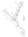
FIGURE 3 shows an exploded view of a chain of shingles and a roof edge trim to which the shingles are electrically connected. -
FIGURE 1 shows abuilding 10 having aroof 12 that is being covered byshingles 14. The shingles protect the roof from rain, snow, wind and other weather conditions. Roof shingles shield are arranged side-by-side inrows 15. Each row of shingle partially overlaps a lower row and is partially overlapped by an upper row. The rows of shingles cover the entire roof. Shingles and conventionally installed by nailing 17 each shingle to the row and arranging the singles in a row. When one row of shingles has been nailed to the roof, a second row is formed by partially overlapping the shingles over the prior row and nailing the shingles to the roof. - The
shingles 14 each include aphotovoltaic panel 16 that is exposed to the sun. The photovoltaic panel is affixed to the portion of the shingle that is exposed when the shingles are affixed to the roof. The other portion of the shingle is anail down sheet 18 that does not include a photovoltaic panel. The nail down sheet is covered by an overlapping shingle when affixed to the roof. The shingles are preferably arranged on the roof such that an entire surface of aroof 12 is covered with photovoltaic panels. - The
shingles 14 are electrically connected to each other along rows of shingles. Each shingle includes two male connectors along one side and two female connectors along its opposite side. The male connectors and female connectors in each shingle are connected to each other by conductive busses that span the width of the single. The photovoltaic cells in the shingle are electrically connected to one or both of the busses in the shingle. - The shingles are installed side-by-side on a roof. The side-by-side installation forms
rows 15 of shingles on the roof. As each shingle is positioned on the roof next to another shingle, one or more electrical connectors on the side of the single are inserted into mating electrical connectors on a side of the another shingle. The connection between electrical connectors on the sides of the singles is formed as one shingle is positioned next to another shingle. Preferably, the connection is formed simply by sliding one connector into another. It is preferred that the electrical connection between the photovoltaic panels on adjacent shingles is formed by simply inserting one or more connectors on one side of a shingle into the mating connector(s) on an opposite side of another connector. - The installation action of positioning one shingle next to another single in a row of shingles on a roof is a conventional installation method commonly used by roofers. Substantially the same conventional installation action is used to install
shingles 14 havingphotovoltaic panels 16 and electrically connect the panels to adjacent shingles. As the roofer applies a new shingle, he or she positions the shingle next to the last installed shingle in a row and slides the connector of the new shingle into the mating connector in the last installed shingle. It is preferably not necessary for the roofer to perform additional steps to electrically connect shingles, such as splicing connecting wires together, extending wires through the roof or adjusting connections. The installation process is preformed by using conventional roofing practices applied to install conventional shingles, with the slight modification that connectors on the sides of the shingles are coupled as the shingles are placed on the roof. -
FIGURE 2 is a plan view of ashingle 14 that includes a solarphotovoltaic panel 16 and a nail-down sheet 18. When theshingle 14 is installed on a roof, thephotovoltaic panel 16 is exposed to the sun and the nail-down sheet underlies an adjacent shingle(s). Preferably the nail-down sheet 18 has substantially the same surface dimensions as does the photovoltaic panel. The nail-down sheet forms a support base for the photovoltaic panel of the shingle installed in an adjacent row. The nail down sheet may be a conventional roofing shingle material, such as a asphalt and fiber sheet, a plastic sheet or other non-woven material. Preferably, the nail-down sheet is deformable and conforms to the bottom surface of the photovoltaic panel installed over the nail-down sheet. - The nail-
down sheet 18 may form a base substrate for the photovoltaic panel of the shingle. The photovoltaic panel may be mounted on one half of the nail-down sheet. The remaining half of the nail-down sheet is exposed to be attached to the roof and to provide a support base for the photovoltaic panels of the shingles in the adjacent row. The nail-down sheet may provide the weather protection for the roof that is provided by conventional shingles. - Each shingle has one or more
photovoltaic panels 16. Each panel is formed ofphotovoltaic cells 22. Preferably, the photovoltaic cells and panels are flexible, at least to the same degree of that a conventional asphalt shingle is flexible. However, flexibility of thepanels 16 is not required, as some conventional shingles, e.g., slate, are not flexible. - The
shingles 14 are typically rectangular in shape and may have dimensions of one to two feet (0.3 to 0.6 meter) by three to four feed (1.0 meter by 1.3 meter). The dimensions of the shingle are a matter of design choice. Half-width shingles 19 may be used at the ends of alternating rows to ensure that each row of shingles is offset horizontally from the adjacent rows. The offset allows the nail-down sheet of each shingle to overlap the gap between the nail-down sheets of adjacent shingles in the preceding row. - Each
shingle 14 has at least onebus second buses panel 16 approximately one third of the height (H) of the panel. Thebusses Figure 2 to represent that the busses are below thepanels 16. Thebuses busses panel 16 and preferably onebus 24a is connected to the positive terminals of thecells 22 in thepanels 16 and theother bus 24b is connected to the negative terminals of the cells. - One end of each
bus male connector 26 that protrudes from the side of the shingle. The male connector preferably extends laterally from theside 28 of the shingle. The other end of eachbus female connector 30 adapted to receive a male connector of a bus from an adjacent shingle. The female connector may be aligned with or slightly recessed under the edge of theshingle 28. - When shingles are arranged side-by-side the
male connectors 26 on one side of a shingle couples with, e.g., slides into, thefemale connectors 30 on the opposite side of an adjacent shingle. The coupling of the male and female connectors electrically connects thebuses - A
transparent sheet 32 may extend from theside 28 of a shingle having the female connector. The transparent sheet covers the gap between the sides of adjacent shingles and shields the coupledconnectors photovoltaic panel 16 without blocking or reducing the sunlight that passes through the transparent sheet. In addition or as an alternative to the sheet, a deformable gasket may extend around each female connector. The gasket protects the coupling between the connectors by sealing around the male connector or bus of the adjacent bus when the male connector is slid into the female connector. -
FIGURE 3 shows howshingles 14 in a row 34 are electrically connected to all of the shingles in the row. Further, each single is physically connected to the adjacent shingles in the row by the coupling of the male andfemale connectors terminal conductor buses 36, e.g., a bus bar, attached to an edge of the roof. Theterminal conductor bus 36 is physically connected to theshingle 38 at the end of the row 34 by the coupling between the male connector of the shingle and thefemale connector 40 of the terminal conductor bus. - The
terminal conductor bus 36 may be a a pair of conductive bars, e.g. a strip or bar of aluminum, each having along one side a row offemale connectors 40. The pair of bars 34 may include a conductive bar for the positive voltage from the photovoltaic cells and a second conductor bar for the negative voltage from the photovoltaic cells. Each of thebuses 36 may have an associatedfemale connector 40 to receive the male connector of the corresponding positive ornegative bus shingle 38 at the end of each row of shingles. Further, alateral end 42 of each conductor bar 34 may be connected to wiring 44 to a batteries or other electricalpower storage system 46 for capturing the electrical power generated in the cells of thephotovoltaic panels 16 mounted on the roof. - The
terminal conductor buses 36 may include ahousing 48, e.g., a plastic channel that shields the conductor bars 36 from weather conditions and includes an attachment strip for affixing, e.g., by nailing, the terminal conductor bus to an edges of the roof. The housing may include atransparent overhang ledge 50 that shields the coupling between the male connectors of the end shingles that are inserted in thefemale connectors 40 of theterminal conductor buses 40. - The terminal
conductive buses 40 provide a conductive path for power from the photovoltaic panels in the rows of shingles. Current from thepanels 16 flows through the positive andnegative buses connected buses terminal conductor buses 36 and to abattery storage device 46, rectifier or other electrical device that captures the generated power and makes the power available for use in the building or for other purposes. Current passes through theconductor buses - To install the shingles on the roof, a first row of shingles is affixed along a lower edge of the roof by nailing the nail-
down sheet 18 to the roof. Thenails 17 or staples extend through the nail-down sheet and secure the shingle to the roof. The affixing of the shingle to the roof is preformed in a conventional manner commonly used by roofers. - A second shingle is positioned on the roof adjacent the first shingle and along the lower edge of the roof to form a first row of shingles. When the second shingle is positioned on the roof, its male connectors are slid into the female connectors of the first shingle. When the male and female connectors are coupled together, the
buses -
Nails 17 are inserted through the nail-down sheet 18 of the second shingle to affix the shingle to the roof. The steps of positioning a new shingle next to a newly affixed shingle in a row shingles, coupling the connectors and affixing the new shingle to the roof are repeated until the row of shingles is completed. - When a first row of shingles is affixed to the roof, a second row of shingles is placed on the roof. The shingles of the second row overlap with the nail down sheet of the shingles in the first row. The rows are arranged such that the photovoltaic panels effectively cover the entire roof.
- Each shingle of the next row is on a nail-down sheet of one or more of shingles in the preceding row. The nail-down sheet of the shingle in the next row is nailed to the roof. Each row of shingles is formed by connecting side-by-side shingles and nailing the nail-down sheet to the roof. Rows of shingles are installed on a roof until the entire roof is covered. The sides of the shingles slide into each other to connect electrically all of the shingles in a row. The connections between the shingles effectively extend the busses in each shingle along the entire row of shingles.
- The
terminal conductor buses 36 may be affixed to an edge of the roof that is transverse to the rows of the shingles. As the terminal conductor buses are affixed to the roof, the female connectors on the bus receive the male connectors of the shingles on the end of the row. The end of theterminal conductor bus 36 is connected to thewiring 44 of thebattery system 46. - The connections between busses in the shingles ensure that power generated in a shingle will flow through the row of shingles to a common bus at the edge of the roof. An electrical failure in a shingle may disable the photovoltaic cells in the shingle. However, an electrical failure in a shingle should not disable the bus or prevent electrical current passing through the busses in the shingle. Accordingly, an electrical failure of the photovoltaic cells in a shingle should not prevent current generated in other shingles in the same row from reaching the common bus at the edge of the roof.
- The shingles and terminal conductor buses may be installed on a roof in much the same manner as conventional shingles. The shingles and terminal buses are affixed to the roof in a conventional manner, such as by being nailed to the roof. A roofer need not have specialized electrical skills to couple the connectors of adjacent shingles or connect an end shingle to the terminal conductor bus. By using conventional techniques for installation, the cost and difficulty of installing the shingles and terminal conductor buses is significantly reduced as compared to installing conventional roofing shingles.
- While the invention has been described in connection with what is presently considered to be the most practical and preferred embodiment, it is to be understood that the invention is not to be limited to the disclosed embodiment, but on the contrary, is intended to cover various modifications and equivalent arrangements included within the spirit and scope of the appended claims.
- Various aspects and embodiments of the present invention will now be defined in connection with the following numbered clauses:
- 1. A shingle comprising:
- a flexible sheet;
- a photovoltaic panel attached to the flexible sheet;
- an electrical conductive path extending from a first side of the shingle to an opposite side of the shingle;
- a connector on one end of the electrical conductive path, and
- a mating connector on an opposite end of the electrical conductive path.
- 2. The shingle as in clause 1 wherein the connector is a male connector and the mating connector is a female connector.
- 3. The shingle as in any preceding clause wherein the connector extends from first side of the shingle and the mating connector extends from the opposite side of the shingle.
- 4. The shingle as in any preceding clause wherein the mating connector is adapted to receive the connector on another shingle.
- 5. The shingle as in any preceding clause wherein the an electrical conductive path includes a positive conductive path and a separate negative conductive path, and the positive and conductive paths each having a connector on one end and a mating connector on an opposite end of the respective paths.
- 6. The shingle as in any preceding clause wherein the flexible sheet underlies the photovoltaic panel.
- 7. The shingle as in clause 1 wherein an area of the photovoltaic panel is within fifty percent of an area of the flexible sheet extending laterally from the panel.
- 8. The shingle as in any preceding clause wherein the electrical conductive path is a conductive bus bar.
- 9. A roofing assembly comprising:
- a plurality of shingles, wherein each shingle includes a photovoltaic panel, an electrical conductive path extending from a first side of the shingle to an opposite side of the shingle and receiving power generated in the photovoltaic panel, a first connector on one end of the electrical conductive path, and a second connector on an opposite end of the electrical conductive path;
- a row of said shingles wherein the shingles are arranged side-by-side on a roof and, in the row, the first connector and second connector are connected for side-by-side shingles and the connected connectors establish an extended conductive path through each of the conductive paths in the shingles of the row, and
- a termination bus connected the first connector of one of said shingles in the row, wherein the termination bus includes a termination conductive path extending substantially transverse to the row of shingles and said termination conductive path is electrically coupled to each shingle in the row.
- 10. The roofing assembly in clause 9 wherein the termination bus is connected to a plurality of rows of the shingles.
- 11. The roofing assembly in
clause 9 or 10 wherein the termination bus includes a plurality of second connectors to each receive a first connector of the one of said shingles in the row. - 12. The roofing assembly in any of clauses 9 to 11 wherein the termination bus is attached to an edge of a roof of a building.
- 13. The roofing assembly in any of clauses 9 to 12 wherein the termination bus is attached to an end of the row and the one of said shingles in the row is at an end of the row of the shingles.
- 14. A method of installing roofing shingles having photovoltaic panels on a roof, wherein each of the roofing shingles includes a conductive bus extending from one side of the shingle to an opposite side of the shingle and one end of the conductive bus includes a first connector and a second end of the bus includes a second connector, the method comprising:
- affixing a first shingle of said shingles to the roof;
- arranging a second shingle of said shingles on the roof and in a row with the first shingle;
- coupling of the first connector of the second shingle with the second connector of the first shingle;
- affixing the second shingle to the roof;
- repeating with successive shingles the arranging, coupling and affixing steps to form a row of shingles on the roof by arranging another single on the roof next to an affixed shingle, and
- inserting the first connector of a shingle at the end of the row into a termination conductive bus transverse to the row and affixed to the roof, wherein the termination conductive bus is electrically connected to the shingles in the row by the conductive bus in the shingles of the row and the coupling between the first and second connectors of the shingles.
- 15. The method of
clause 14 further forming successive rows of shingles by affixing, arranging and coupling the shingles and inserting the first connector of a shingle at the end of each successive row into a respective second connector in the termination conductive bus, wherein the termination bus is electrically connected to the conductive bus in each shingle in the successive rows. - 16. The method of
clause - 17. The method of any of
clauses 14 to 16 wherein the coupling of the first connector with the second connector is achieved by inserting the first connector into the second connector as the shingles are arranged on the roof. - 18. The method of any of
clauses 14 to 17 wherein the first and second connectors are male and female connectors that are coupled by sliding the male connector into the female connector. - 19. The method of any of
clauses 14 to 18 further comprising positioning a clear panel over the sides of the shingles to cover the coupling between the first and second connectors. - 20. The method of any of
clauses 14 to 19 wherein the steps are performed sequentially.
Claims (10)
- A shingle (14)comprising:a flexible sheet (18);a photovoltaic panel (16) attached to the flexible sheet;an electrical conductive path (24a, 24b) extending from a first side (28) of the shingle to an opposite side (28) of the shingle;a connector (26) on one end of the electrical conductive path, anda mating connector (30) on an opposite end of the electrical conductive path.
- The shingle (14) as in claim 1 wherein the connector is a male connector (26) and the mating connector is a female connector (30).
- The shingle (14) as in any preceding claim wherein the connector (26) extends from first side of the shingle and the mating connector (30) is at the opposite side of the shingle.
- The shingle (14) as in any preceding claim wherein the mating connector (30) is adapted to receive the connector (26) on another shingle.
- The shingle (14) as in any preceding claim wherein the an electrical conductive path includes a positive conductive path (24a) and a separate negative (24b) conductive path, and the positive and conductive paths each having a connector (26) on one end and a mating connector (30) on an opposite end of the respective paths.
- A roofing assembly comprising:a plurality of shingles (14), wherein each shingle includes a photovoltaic panel (16), an electrical conductive path (24a, 24b) extending from a first side (28) of the shingle to an opposite side (28) of the shingle and receiving power generated in the photovoltaic panel, a first connector (26) on one end of the electrical conductive path, and a second connector (30) on an opposite end of the electrical conductive path;a row (15) of said shingles wherein the shingles are arranged side-by-side on a roof (12) and, in the row, the first connector and second connector are connected for side-by-side shingles and the connected connectors establish an extended conductive path through each of the conductive paths in the shingles of the row, anda termination bus (36) connected the first connector of one of said shingles in the row, wherein the termination bus includes a termination conductive path extending substantially transverse to the row of shingles and said termination conductive path is electrically coupled (40) to each shingle in the row.
- The roofing assembly in claim 6 wherein the termination bus includes a plurality of second connectors (40) to each receive a first connector (26) of the one of said shingles in the row.
- The roofing assembly in claim 6 or claim 7 wherein the termination bus (36) is attached to an edge (50) of a roof of a building.
- A method of installing roofing shingles (14) having photovoltaic panels (16) on a roof (12), wherein each of the roofing shingles includes a conductive bus (24a, 24b) extending from one side of the shingle to an opposite side of the shingle and one end of the conductive bus includes a first connector (26) and a second end of the bus includes a second connector (30), the method comprising:affixing a first shingle of said shingles to the roof;arranging a second shingle of said shingles on the roof and in a row with the first shingle;coupling of the first connector of the second shingle with the second connector of the first shingle;affixing the second shingle to the roof;repeating with successive shingles the arranging, coupling and affixing steps to form a row of shingles on the roof by arranging another single on the roof next to an affixed shingle, andinserting the first connector of a shingle at the end of the row into a termination conductive bus (36) transverse to the row and affixed to the roof, wherein the termination conductive bus is electrically connected (40) to the shingles in the row by the conductive bus in the shingles of the row and the coupling between the first and second connectors of the shingles.
- The method of claim 9 further forming successive rows of shingles by affixing, arranging and coupling the shingles and inserting the first connector of a shingle (38) at the end of each successive row into a respective second connector (40) in the termination conductive bus, wherein the termination bus is electrically connected to the conductive bus (24a, 24b) in each shingle in the successive rows.
Applications Claiming Priority (1)
| Application Number | Priority Date | Filing Date | Title |
|---|---|---|---|
| US12/147,909 US8507784B2 (en) | 2008-06-27 | 2008-06-27 | Photovoltaic shingles for roofing and method for connecting the shingles |
Publications (2)
| Publication Number | Publication Date |
|---|---|
| EP2139043A2 true EP2139043A2 (en) | 2009-12-30 |
| EP2139043A3 EP2139043A3 (en) | 2017-04-12 |
Family
ID=41203664
Family Applications (1)
| Application Number | Title | Priority Date | Filing Date |
|---|---|---|---|
| EP09163093.9A Withdrawn EP2139043A3 (en) | 2008-06-27 | 2009-06-18 | Photovoltaic shingles for roofing and method for connecting the shingles |
Country Status (4)
| Country | Link |
|---|---|
| US (1) | US8507784B2 (en) |
| EP (1) | EP2139043A3 (en) |
| CN (1) | CN101614057B (en) |
| AU (1) | AU2009202491B2 (en) |
Cited By (6)
| Publication number | Priority date | Publication date | Assignee | Title |
|---|---|---|---|---|
| WO2011011367A1 (en) * | 2009-07-20 | 2011-01-27 | E. I. Du Pont De Nemours And Company | Photovoltaic panel having a keying feature thereon |
| NL1037791C2 (en) * | 2010-03-09 | 2011-09-12 | Roy Ronald Verlaak | SOLAR PANEL. |
| WO2013019637A1 (en) * | 2011-07-29 | 2013-02-07 | Dow Global Technologies Llc | Photovoltaic devices with an improved positioning and locking features and method of assembly |
| FR2979753A1 (en) * | 2011-09-05 | 2013-03-08 | Alexandre Azoulay | Electric junction tile for use in building roof covering assembly to connect photovoltaic tiles, has conductors connecting inter-line connector with one of inter-row connectors at input, and connecting other inter-row connectors at output |
| EP2533302A3 (en) * | 2011-06-08 | 2013-10-09 | Robert Bosch Gmbh | Solar module and photovoltaic assembly |
| JP2014529988A (en) * | 2011-09-01 | 2014-11-13 | コミッサリアア レネルジー アトミーク エ オ エナジーズ アルタナティブス | Photovoltaic module with improved mechanical and electrical links |
Families Citing this family (27)
| Publication number | Priority date | Publication date | Assignee | Title |
|---|---|---|---|---|
| US20100108118A1 (en) * | 2008-06-02 | 2010-05-06 | Daniel Luch | Photovoltaic power farm structure and installation |
| US9865758B2 (en) | 2006-04-13 | 2018-01-09 | Daniel Luch | Collector grid and interconnect structures for photovoltaic arrays and modules |
| US8884155B2 (en) | 2006-04-13 | 2014-11-11 | Daniel Luch | Collector grid and interconnect structures for photovoltaic arrays and modules |
| FR2914785B1 (en) * | 2007-04-06 | 2009-05-15 | Saint Gobain Ct Recherches | PHOTOVOLTAIC ROOF COATING |
| US11473741B2 (en) | 2007-05-31 | 2022-10-18 | Aaron Chien | LED light has built-in air related part(s) |
| KR101249275B1 (en) * | 2008-05-05 | 2013-04-01 | 다우 글로벌 테크놀로지스 엘엘씨 | System for installation photovoltaic devices on a structure |
| US8511006B2 (en) | 2009-07-02 | 2013-08-20 | Owens Corning Intellectual Capital, Llc | Building-integrated solar-panel roof element systems |
| US8656657B2 (en) * | 2009-08-31 | 2014-02-25 | Certainteed Corporation | Photovoltaic roofing elements |
| IT1401388B1 (en) * | 2010-07-29 | 2013-07-18 | St Microelectronics Srl | COVERAGE COVER WITH INCORPORATING TILES ORGANS OF PHOTOVOLTAIC CONVERSION WITH CONCENTRATION AND SOLAR ENERGY THERMAL |
| US20120240485A1 (en) * | 2011-03-24 | 2012-09-27 | Amarasinghe Disamodha C | Panel construction system |
| US8782972B2 (en) | 2011-07-14 | 2014-07-22 | Owens Corning Intellectual Capital, Llc | Solar roofing system |
| CN103015644A (en) * | 2012-10-23 | 2013-04-03 | 江卫青 | Point installation method of photovoltaic module |
| UA118883C2 (en) | 2014-07-01 | 2019-03-25 | Арселорміттал | PANEL WITH PHOTOELECTRIC DEVICE |
| US10224701B2 (en) * | 2017-05-01 | 2019-03-05 | Bluescope Buildings North America, Inc. | Modular structural and electrical building system |
| US10505493B2 (en) | 2017-07-18 | 2019-12-10 | Tesla, Inc. | Building integrated photovoltaic tile mounting system |
| US10081944B1 (en) * | 2017-09-21 | 2018-09-25 | Newtonoid Technologies, L.L.C. | Shingle clip system and method |
| US10693413B2 (en) | 2017-10-19 | 2020-06-23 | Building Materials Investment Corporation | Roof integrated photovoltaic system |
| US20190237905A1 (en) * | 2018-01-29 | 2019-08-01 | David Lynn | Panels with Mirrored Connectivity |
| MX2022006401A (en) * | 2019-11-27 | 2022-10-27 | GAF Energy LLC | INTEGRATED ROOF PHOTOVOLTAIC MODULE WITH SPACER. |
| US12261428B2 (en) * | 2020-03-05 | 2025-03-25 | David Lynn | Protective mesh array for use within an electrical network |
| WO2024095056A1 (en) * | 2022-11-03 | 2024-05-10 | Bmic Llc | Embossed roofing membrane and shingle, and associated roofing system |
| US12244262B2 (en) | 2023-01-09 | 2025-03-04 | Sarcos Corp. | Capture and support mount for retaining installed solar panels |
| US20240235470A1 (en) * | 2023-01-09 | 2024-07-11 | Sarcos Corp. | Auto-Engaging Electrical Connections for Solar Panels |
| US12466066B2 (en) | 2023-05-04 | 2025-11-11 | Sarcos Corp. | Solar panel dispensing device with vertical solar panel hopper loading and dispensing |
| US12570001B2 (en) | 2024-01-08 | 2026-03-10 | Sarcos Corp. | Support clamp installation vehicles as part of a solar panel installation system for a solar tracking system |
| US12542513B2 (en) | 2024-01-08 | 2026-02-03 | Sarcos Corp. | Torque tube clamps for automated solar panel installation |
| US20240266987A1 (en) * | 2024-03-08 | 2024-08-08 | Wencon Development, Inc., Dba Quick Mount Pv | Waterproofing Mounting System for Attaching Solar Modules to a Roof |
Family Cites Families (35)
| Publication number | Priority date | Publication date | Assignee | Title |
|---|---|---|---|---|
| GB1234828A (en) | 1968-10-14 | 1971-06-09 | Mini Of Aviat Supply | Solar cell arrays |
| US4040867A (en) | 1976-08-24 | 1977-08-09 | The United States Of America As Represented By The Administrator Of The National Aeronautics And Space Administration | Solar cell shingle |
| DE3427574A1 (en) | 1984-07-26 | 1986-02-06 | Stromeyer Ingenieurbau GmbH, 7750 Konstanz | DEVICE FOR SHADING SURFACES |
| US4674244A (en) | 1986-07-17 | 1987-06-23 | Single-Ply Institute Of America, Inc. | Roof construction having insulation structure, membrane and photovoltaic cells |
| US4860509A (en) | 1987-05-18 | 1989-08-29 | Laaly Heshmat O | Photovoltaic cells in combination with single ply roofing membranes |
| DE59010720D1 (en) | 1989-01-17 | 1997-07-10 | Webasto Systemkomponenten Gmbh | Device with a flexible surface for holding photovoltaic cells |
| DE4240616A1 (en) | 1992-12-03 | 1994-06-09 | Westsolar Gmbh | Solar cell arrangement |
| DE4317674A1 (en) | 1993-05-27 | 1994-12-01 | Juergens Walter | Solar-cell receiving system (solar cassette) |
| JP3570738B2 (en) | 1993-07-28 | 2004-09-29 | 富士電機ホールディングス株式会社 | Solar power roof |
| US5575861A (en) | 1993-12-30 | 1996-11-19 | United Solar Systems Corporation | Photovoltaic shingle system |
| JPH08114013A (en) | 1994-10-17 | 1996-05-07 | Fuji Electric Co Ltd | Photovoltaic roof material and construction method |
| JPH0951118A (en) | 1995-08-09 | 1997-02-18 | Shiroki Corp | Sheet solar cell |
| JP3396568B2 (en) | 1995-11-14 | 2003-04-14 | ミサワホーム株式会社 | Mounting structure for sheet solar cells |
| DE29619119U1 (en) | 1996-09-23 | 1998-01-22 | Atlantis Solar Systeme AG, Bern | Photovoltaic solar roof |
| US5968287A (en) | 1997-05-16 | 1999-10-19 | United Solar Systems Corporation | Power generating building panels and methods for their manufacture |
| US6148570A (en) | 1998-02-05 | 2000-11-21 | Powerlight Corporation | Photovoltaic building assembly with continuous insulation layer |
| JP3229243B2 (en) | 1997-06-30 | 2001-11-19 | 太陽工業株式会社 | Solar power generator |
| JPH1140835A (en) * | 1997-07-17 | 1999-02-12 | Sekisui Chem Co Ltd | Solar cell module and roof on which solar cell module is installed |
| DE19828462A1 (en) | 1998-06-26 | 2000-01-05 | Alwitra Gmbh & Co Klaus Goebel | Roof sealing strip for protection of building structure |
| JP2000145015A (en) | 1998-09-01 | 2000-05-26 | Sumitomo Metal Mining Co Ltd | Panel with solar cell |
| JP3718353B2 (en) | 1998-10-21 | 2005-11-24 | 旭化成建材株式会社 | Solar cell module mounting structure and solar cell module |
| JP3718067B2 (en) | 1998-11-13 | 2005-11-16 | 旭化成建材株式会社 | Solar cell integrated roofing material |
| JP2000164909A (en) | 1998-11-30 | 2000-06-16 | Nisshin Steel Co Ltd | Thin-film solar cell and manufacture of it |
| JP2000150949A (en) | 2000-01-01 | 2000-05-30 | Canon Inc | Solar cell module |
| JP2001332752A (en) | 2000-05-19 | 2001-11-30 | Canon Inc | Solar cell module, method of transporting the same, method of constructing the same, and solar power generation device |
| US6729081B2 (en) | 2000-06-09 | 2004-05-04 | United Solar Systems Corporation | Self-adhesive photovoltaic module |
| US6553729B1 (en) | 2000-06-09 | 2003-04-29 | United Solar Systems Corporation | Self-adhesive photovoltaic module |
| US6660930B1 (en) | 2002-06-12 | 2003-12-09 | Rwe Schott Solar, Inc. | Solar cell modules with improved backskin |
| US6928775B2 (en) * | 2002-08-16 | 2005-08-16 | Mark P. Banister | Multi-use electric tile modules |
| JP2004221151A (en) * | 2003-01-10 | 2004-08-05 | Fuji Electric Holdings Co Ltd | Roof material integrated solar cell module |
| US7342171B2 (en) | 2003-01-23 | 2008-03-11 | Solar Intergrated Technologies, Inc. | Integrated photovoltaic roofing component and panel |
| US20050072456A1 (en) | 2003-01-23 | 2005-04-07 | Stevenson Edward J. | Integrated photovoltaic roofing system |
| WO2006098974A1 (en) * | 2005-03-11 | 2006-09-21 | Bp Corporation North America Inc. | Integrated solar cell roofing system and method of manufacture |
| JP2007019140A (en) * | 2005-07-06 | 2007-01-25 | Itogumi Mokuzai Kk | Solar cell module, its connection method, installation structure, and installation method |
| US20080149170A1 (en) * | 2006-12-15 | 2008-06-26 | Evergreen Solar, Inc. | Plug-Together Photovoltaic Modules |
-
2008
- 2008-06-27 US US12/147,909 patent/US8507784B2/en not_active Expired - Fee Related
-
2009
- 2009-06-18 EP EP09163093.9A patent/EP2139043A3/en not_active Withdrawn
- 2009-06-22 AU AU2009202491A patent/AU2009202491B2/en not_active Ceased
- 2009-06-29 CN CN200910158645.7A patent/CN101614057B/en not_active Expired - Fee Related
Non-Patent Citations (1)
| Title |
|---|
| None * |
Cited By (8)
| Publication number | Priority date | Publication date | Assignee | Title |
|---|---|---|---|---|
| WO2011011367A1 (en) * | 2009-07-20 | 2011-01-27 | E. I. Du Pont De Nemours And Company | Photovoltaic panel having a keying feature thereon |
| WO2011011369A1 (en) * | 2009-07-20 | 2011-01-27 | E. I. Du Pont De Nemours And Company | Solar array incorporating photovoltaic panels having keying features thereon and method for installing the same |
| WO2011011374A1 (en) * | 2009-07-20 | 2011-01-27 | E. I. Du Pont De Nemours And Company | Solar array incorporating a photovoltaic panel and a framework element each having keying features thereon and method for installing the same |
| NL1037791C2 (en) * | 2010-03-09 | 2011-09-12 | Roy Ronald Verlaak | SOLAR PANEL. |
| EP2533302A3 (en) * | 2011-06-08 | 2013-10-09 | Robert Bosch Gmbh | Solar module and photovoltaic assembly |
| WO2013019637A1 (en) * | 2011-07-29 | 2013-02-07 | Dow Global Technologies Llc | Photovoltaic devices with an improved positioning and locking features and method of assembly |
| JP2014529988A (en) * | 2011-09-01 | 2014-11-13 | コミッサリアア レネルジー アトミーク エ オ エナジーズ アルタナティブス | Photovoltaic module with improved mechanical and electrical links |
| FR2979753A1 (en) * | 2011-09-05 | 2013-03-08 | Alexandre Azoulay | Electric junction tile for use in building roof covering assembly to connect photovoltaic tiles, has conductors connecting inter-line connector with one of inter-row connectors at input, and connecting other inter-row connectors at output |
Also Published As
| Publication number | Publication date |
|---|---|
| AU2009202491B2 (en) | 2015-04-16 |
| CN101614057A (en) | 2009-12-30 |
| US20090320389A1 (en) | 2009-12-31 |
| US8507784B2 (en) | 2013-08-13 |
| AU2009202491A1 (en) | 2010-01-14 |
| CN101614057B (en) | 2016-05-18 |
| EP2139043A3 (en) | 2017-04-12 |
Similar Documents
| Publication | Publication Date | Title |
|---|---|---|
| US8507784B2 (en) | Photovoltaic shingles for roofing and method for connecting the shingles | |
| US8789321B2 (en) | Roof structure, clamp for solar cell module, and method for mounting solar cell module | |
| AU720253B2 (en) | A photovoltaic solar roof | |
| US20080302409A1 (en) | Solar roofing tile having an electrically exposed connector | |
| US8853520B2 (en) | Solar cell module, arrangement structure of the same, and method for arranging the same | |
| US20130212959A1 (en) | Asphalt shingle solar power device, system and installation method | |
| CN101220700A (en) | Method and system for integrating photovoltaic modules in asphalt roofs | |
| JPWO2020054197A1 (en) | Installation structure of solar panel | |
| EP2398059B1 (en) | Roof with roof tile provided with solar cells | |
| JP5557548B2 (en) | Roof structure | |
| JP5574739B2 (en) | ROOF STRUCTURE, SOLAR CELL MODULE MOUNTING DEVICE, AND SOLAR CELL MODULE MOUNTING METHOD | |
| JP2004132123A (en) | Roof material integrated solar cell module and wiring method thereof | |
| JP4326990B2 (en) | Roof material integrated solar cell module | |
| JP3823947B2 (en) | Roof material separation type solar cell module | |
| US12580517B2 (en) | Photovoltaic roofing tile foot | |
| JP3296962B2 (en) | Roof panel wiring structure | |
| JP5574741B2 (en) | ROOF STRUCTURE, SOLAR CELL MODULE MOUNTING DEVICE, AND SOLAR CELL MODULE MOUNTING METHOD | |
| US20240204713A1 (en) | Photovoltaic roofing tile base | |
| US12567832B2 (en) | Solar roof tile | |
| JP2000282647A (en) | Solar cell module | |
| JP2002276086A (en) | Solar battery module | |
| JP4136541B2 (en) | ROOF MATERIAL INTEGRATED SOLAR CELL MODULE AND ITS LAYING METHOD |
Legal Events
| Date | Code | Title | Description |
|---|---|---|---|
| PUAI | Public reference made under article 153(3) epc to a published international application that has entered the european phase |
Free format text: ORIGINAL CODE: 0009012 |
|
| AK | Designated contracting states |
Kind code of ref document: A2 Designated state(s): AT BE BG CH CY CZ DE DK EE ES FI FR GB GR HR HU IE IS IT LI LT LU LV MC MK MT NL NO PL PT RO SE SI SK TR |
|
| PUAL | Search report despatched |
Free format text: ORIGINAL CODE: 0009013 |
|
| AK | Designated contracting states |
Kind code of ref document: A3 Designated state(s): AT BE BG CH CY CZ DE DK EE ES FI FR GB GR HR HU IE IS IT LI LT LU LV MC MK MT NL NO PL PT RO SE SI SK TR |
|
| AX | Request for extension of the european patent |
Extension state: AL BA RS |
|
| RIC1 | Information provided on ipc code assigned before grant |
Ipc: H01L 31/048 20140101ALI20170308BHEP Ipc: H01L 31/02 20060101AFI20170308BHEP |
|
| 17P | Request for examination filed |
Effective date: 20171012 |
|
| RBV | Designated contracting states (corrected) |
Designated state(s): AT BE BG CH CY CZ DE DK EE ES FI FR GB GR HR HU IE IS IT LI LT LU LV MC MK MT NL NO PL PT RO SE SI SK TR |
|
| 17Q | First examination report despatched |
Effective date: 20180413 |
|
| STAA | Information on the status of an ep patent application or granted ep patent |
Free format text: STATUS: THE APPLICATION IS DEEMED TO BE WITHDRAWN |
|
| 18D | Application deemed to be withdrawn |
Effective date: 20180824 |