EP2138983A2 - Article storage and retrieval apparatus and vending machine - Google Patents
Article storage and retrieval apparatus and vending machine Download PDFInfo
- Publication number
- EP2138983A2 EP2138983A2 EP09275017A EP09275017A EP2138983A2 EP 2138983 A2 EP2138983 A2 EP 2138983A2 EP 09275017 A EP09275017 A EP 09275017A EP 09275017 A EP09275017 A EP 09275017A EP 2138983 A2 EP2138983 A2 EP 2138983A2
- Authority
- EP
- European Patent Office
- Prior art keywords
- comprised
- vending machine
- recited
- controller
- tube
- Prior art date
- Legal status (The legal status is an assumption and is not a legal conclusion. Google has not performed a legal analysis and makes no representation as to the accuracy of the status listed.)
- Granted
Links
- 238000003860 storage Methods 0.000 title claims description 37
- 230000007246 mechanism Effects 0.000 claims description 103
- 238000012384 transportation and delivery Methods 0.000 claims description 53
- 230000033001 locomotion Effects 0.000 claims description 42
- 238000005057 refrigeration Methods 0.000 claims description 25
- VYZAMTAEIAYCRO-UHFFFAOYSA-N Chromium Chemical compound [Cr] VYZAMTAEIAYCRO-UHFFFAOYSA-N 0.000 claims description 10
- 235000013361 beverage Nutrition 0.000 claims description 9
- 239000011248 coating agent Substances 0.000 claims description 9
- 238000000576 coating method Methods 0.000 claims description 9
- 239000000758 substrate Substances 0.000 claims description 8
- 239000000956 alloy Substances 0.000 claims description 6
- 230000000670 limiting effect Effects 0.000 claims description 6
- 229910001092 metal group alloy Inorganic materials 0.000 claims description 6
- 238000007747 plating Methods 0.000 claims description 6
- 229920002379 silicone rubber Polymers 0.000 claims description 5
- 239000004945 silicone rubber Substances 0.000 claims description 5
- 229910001369 Brass Inorganic materials 0.000 claims description 4
- 239000010951 brass Substances 0.000 claims description 4
- 229910052804 chromium Inorganic materials 0.000 claims description 4
- 239000011651 chromium Substances 0.000 claims description 4
- 230000004044 response Effects 0.000 claims description 4
- 239000002982 water resistant material Substances 0.000 claims description 4
- 238000000926 separation method Methods 0.000 claims description 2
- 238000000034 method Methods 0.000 description 61
- 230000008569 process Effects 0.000 description 24
- 230000002452 interceptive effect Effects 0.000 description 19
- 238000004891 communication Methods 0.000 description 15
- 230000002441 reversible effect Effects 0.000 description 13
- 230000032258 transport Effects 0.000 description 13
- 239000011521 glass Substances 0.000 description 10
- 230000009471 action Effects 0.000 description 8
- 230000003287 optical effect Effects 0.000 description 8
- 230000000007 visual effect Effects 0.000 description 7
- 239000004973 liquid crystal related substance Substances 0.000 description 6
- 239000000463 material Substances 0.000 description 6
- 230000036961 partial effect Effects 0.000 description 6
- 238000010586 diagram Methods 0.000 description 4
- 230000000694 effects Effects 0.000 description 4
- 230000006870 function Effects 0.000 description 4
- 230000006872 improvement Effects 0.000 description 4
- 229910000831 Steel Inorganic materials 0.000 description 3
- 230000000712 assembly Effects 0.000 description 3
- 238000000429 assembly Methods 0.000 description 3
- 238000013475 authorization Methods 0.000 description 3
- 230000008901 benefit Effects 0.000 description 3
- 235000020965 cold beverage Nutrition 0.000 description 3
- 235000012171 hot beverage Nutrition 0.000 description 3
- 239000010959 steel Substances 0.000 description 3
- 238000012360 testing method Methods 0.000 description 3
- 238000012550 audit Methods 0.000 description 2
- 230000008859 change Effects 0.000 description 2
- 238000001514 detection method Methods 0.000 description 2
- 238000007689 inspection Methods 0.000 description 2
- 230000003993 interaction Effects 0.000 description 2
- 238000002372 labelling Methods 0.000 description 2
- 238000007726 management method Methods 0.000 description 2
- 238000012544 monitoring process Methods 0.000 description 2
- 239000004033 plastic Substances 0.000 description 2
- 229920003023 plastic Polymers 0.000 description 2
- 238000012545 processing Methods 0.000 description 2
- 238000012546 transfer Methods 0.000 description 2
- 238000007514 turning Methods 0.000 description 2
- XLYOFNOQVPJJNP-UHFFFAOYSA-N water Substances O XLYOFNOQVPJJNP-UHFFFAOYSA-N 0.000 description 2
- 238000012935 Averaging Methods 0.000 description 1
- 244000043261 Hevea brasiliensis Species 0.000 description 1
- 229920000459 Nitrile rubber Polymers 0.000 description 1
- 229910000639 Spring steel Inorganic materials 0.000 description 1
- 230000004888 barrier function Effects 0.000 description 1
- 238000007664 blowing Methods 0.000 description 1
- 230000001413 cellular effect Effects 0.000 description 1
- 230000007797 corrosion Effects 0.000 description 1
- 238000005260 corrosion Methods 0.000 description 1
- 230000008878 coupling Effects 0.000 description 1
- 238000010168 coupling process Methods 0.000 description 1
- 238000005859 coupling reaction Methods 0.000 description 1
- 238000004132 cross linking Methods 0.000 description 1
- 238000002716 delivery method Methods 0.000 description 1
- 238000013461 design Methods 0.000 description 1
- 238000004512 die casting Methods 0.000 description 1
- 125000000118 dimethyl group Chemical group [H]C([H])([H])* 0.000 description 1
- 239000006185 dispersion Substances 0.000 description 1
- 238000009826 distribution Methods 0.000 description 1
- 230000009977 dual effect Effects 0.000 description 1
- 230000007340 echolocation Effects 0.000 description 1
- 238000005516 engineering process Methods 0.000 description 1
- 239000000835 fiber Substances 0.000 description 1
- 239000011888 foil Substances 0.000 description 1
- 238000005286 illumination Methods 0.000 description 1
- 230000006698 induction Effects 0.000 description 1
- 230000010365 information processing Effects 0.000 description 1
- 238000003754 machining Methods 0.000 description 1
- 238000012423 maintenance Methods 0.000 description 1
- 238000004519 manufacturing process Methods 0.000 description 1
- 238000013507 mapping Methods 0.000 description 1
- 238000005259 measurement Methods 0.000 description 1
- 238000012986 modification Methods 0.000 description 1
- 230000004048 modification Effects 0.000 description 1
- 229920003052 natural elastomer Polymers 0.000 description 1
- 229920001194 natural rubber Polymers 0.000 description 1
- 238000005192 partition Methods 0.000 description 1
- 239000002304 perfume Substances 0.000 description 1
- 230000002093 peripheral effect Effects 0.000 description 1
- 229920001296 polysiloxane Polymers 0.000 description 1
- 230000000063 preceeding effect Effects 0.000 description 1
- 238000007639 printing Methods 0.000 description 1
- 238000011084 recovery Methods 0.000 description 1
- 230000002829 reductive effect Effects 0.000 description 1
- 238000010187 selection method Methods 0.000 description 1
- 238000012163 sequencing technique Methods 0.000 description 1
- 230000011664 signaling Effects 0.000 description 1
- 230000003595 spectral effect Effects 0.000 description 1
- 238000001228 spectrum Methods 0.000 description 1
- 230000007704 transition Effects 0.000 description 1
- 238000012795 verification Methods 0.000 description 1
Images


Classifications
-
- G—PHYSICS
- G07—CHECKING-DEVICES
- G07F—COIN-FREED OR LIKE APPARATUS
- G07F11/00—Coin-freed apparatus for dispensing, or the like, discrete articles
- G07F11/02—Coin-freed apparatus for dispensing, or the like, discrete articles from non-movable magazines
- G07F11/38—Coin-freed apparatus for dispensing, or the like, discrete articles from non-movable magazines in which the magazines are horizontal
- G07F11/42—Coin-freed apparatus for dispensing, or the like, discrete articles from non-movable magazines in which the magazines are horizontal the articles being delivered by motor-driven means
-
- G—PHYSICS
- G07—CHECKING-DEVICES
- G07F—COIN-FREED OR LIKE APPARATUS
- G07F11/00—Coin-freed apparatus for dispensing, or the like, discrete articles
- G07F11/02—Coin-freed apparatus for dispensing, or the like, discrete articles from non-movable magazines
- G07F11/04—Coin-freed apparatus for dispensing, or the like, discrete articles from non-movable magazines in which magazines the articles are stored one vertically above the other
- G07F11/16—Delivery means
- G07F11/165—Delivery means using xyz-picker or multi-dimensional article picking arrangements
- G07F11/1657—Delivery means using xyz-picker or multi-dimensional article picking arrangements the picking arrangements using suction
-
- G—PHYSICS
- G07—CHECKING-DEVICES
- G07F—COIN-FREED OR LIKE APPARATUS
- G07F11/00—Coin-freed apparatus for dispensing, or the like, discrete articles
- G07F11/62—Coin-freed apparatus for dispensing, or the like, discrete articles in which the articles are stored in compartments in fixed receptacles
Definitions
- This invention relates to an apparatus and process for storing and selectively retrieving articles, and to a vending machine incorporating such apparatus and process.
- vending machines do not have a way to confirm that the product the customer has selected is the same product delivered to the customer. This is a disadvantage to the customer as well as the vending machine operators. It can lead to accounting errors as well as fraud. For example, some machine operator are subsidized by large corporate brands and are obligated to stock the contractually agreed brands. If the operator substitutes non-branded products for the contracted branded products, this can lead to reduced revenue for the corporate brand as well as a breach of contract.
- an apparatus for moving an article comprising a first telescoping tube movably connected to a second telescoping tube, a suction cup connected to said first telescoping tube, and a drive assembly connected to said first telescoping tube.
- suction cup is a bellows suction cup.
- said bellows suction cup is comprised of from about 1.5 to about 2.5 bellows and has a diameter of from about 0.7 to about 2.0 inches.
- said bellows suction cup had a Durometer Shore A hardness of less than about 56.
- a vending machine comprised of the apparatus according to the first-recited aspect.
- an apparatus for moving an article comprising a first telescoping tube movably connected to a second telescoping tube, and a third telescoping tube movably connected to said second telescoping tube, wherein said first telescoping tube is connected to a suction cup, wherein said apparatus is also comprised of a drive mechanism connected to said first telescoping tube, and wherein (a) said first telescoping tube is comprised of a stop for limiting the motion of said second telescoping tube within said first telescoping tube, and said second telescoping tube is comprised of a stop for limiting the motion of said third telescoping tube within said second telescoping tube.
- said suction cup is a bellows suction cup that is comprised of from about 1.5 to about 2.5 bellows.
- each of said first telescoping tube, said second telescoping tube, and said third telescoping tube is comprised of a substrate and a coating disposed on said substrate.
- said substrate consists essentially of a metal alloy material.
- said metal alloy material is a half hard brass, and wherein said substrate has a thickness of from about 0.01 to about 0.04 inches.
- said coating has a thickness of from about 0.00005 to about 0.001 inches.
- said coating consists essentially of a water-resistant material.
- said water resistant material is chromium plating.
- a apparatus for picking up an article comprised of a suction cup, an arm connected to said suction cup, and a friction drive assembly connected to said arm for moving said arm.
- said apparatus is adapted to move said arm in the X axis, the Y axis, and the Z axis.
- said arm is comprised of a hollow center portion.
- a vacuum source is connected to said hollow center portion of said arm.
- the apparatus is comprised of means for expanding said arm.
- the apparatus is comprised of means for retracting said arm.
- said friction drive assembly is comprised of motor connected to a friction drive roller.
- said friction drive roller is connected to a spring coil.
- said spring coil is a flat spring coil.
- said spring coil is compressed between said friction drive roller and an idler roller.
- said spring coil is connected to said arm.
- an apparatus for storing and selectively retrieving articles comprising a vertical array of storage locations each having a horizontal surface on which articles may rest and along which articles may be slid, a pick mechanism mounted for movement horizontally and vertically across the face of the array so as to be selectively positionable at any one of the locations, wherein the pick mechanism has mounted thereon a telescopic suction tube.
- said apparatus further comprises a suction tube drive assembly connected to said telescopic suction tube.
- suction tube drive assembly is comprised of means for selectively extending and retracting said telescopic tube, and wherein said suction tube drive assembly is also comprised of a pressure detector.
- suction tube drive assembly comprises an an elongate flat strip.
- suction tube drive assembly comprises a friction drive roller.
- suction tube drive assembly comprises an encoder motor.
- suction tube drive assembly comprises a fan driven by a motor mounted on said pick mechanism.
- said suction tube drive assembly is comprised of a suction tube, wherein said suction tube at one end thereof is comprised of an elastic cup that is connected to said suction tube.
- said elastic cup surrounds said suction tube.
- the apparatus is comprised of a support rail, a first vertical rail, and a second vertical rail, wherein said pick mechanism is slidably disposed on said support rail, and wherein said support rail is slidably mounted on said first vertical rail and said second vertical rail.
- the apparatus further comprises a suction tube support plate that is connected to said pick mechanism.
- a vending machine assembly comprising a lockable cabinet, a vending machine disposed within said lockable cabinet, a controller, a pick mechanism comprised of a telescoping tube, and a selector for sending an article selection signal to said controller, and a payment assembly, wherein:
- said cabinet is comprised of a transparent panel.
- vending machine is comprised of a product delivery assembly.
- said product delivery assembly is comprised of a door, wherein said door is disposed within said cabinet.
- said door is comprised of a lock, wherein said lock is operatively connected to said controller.
- said pick mechanism is comprised of a pressure detector assembly.
- the vending machine further comprises an encoder motor and means for reversing the direction of movement of said encoder motor.
- said pressure detector assembly is comprised of means for detecting the pressure within said telescoping tube.
- said controller is comprised of means for halting the movement of said pick mechanism whenever said pressure detector assembly determines that the pressure within said telescoping tube has exceeded a certain predetermined level.
- vending machine is comprised of a suction tube assembly and a contact switch connected to said suction tube assembly and to said controller.
- a vending machine assembly comprised of a control board, a controller embedded in said control board, a three-drive axis mechanism connected to said controller, and two telescoping vacuum tubes each of which is connected to said controller.
- vending machine assembly further comprises a refrigeration module connected to said controller.
- said refrigeration module is comprised of a refrigeration deck.
- the vending machine assembly further comprises a cabinet, wherein said refrigeration deck is disposed in said cabinet.
- the vending machine assembly further comprises a beverage fill station.
- the vending machine assembly further comprises a cup lidding station.
- the vending machine further comprises a bagging station.
- a display and storage system comprised of a frame and a multiplicity of shelves disposed within such frame, wherein each of such shelves is comprised of a base, a first sidewall, and a second sidewall, a first bristle brush connected to said first sidewall and extending along the length of such first sidewall, and a second bristle brush connected to said second side wall and extending along the length of said second side wall.
- the display and storage system comprises a first article removably disposed between said first bristle brush and said second bristle brush.
- each of said first side wall and said second side wall is comprised of a multiplicity oftabs.
- an apparatus for storing and selectively retrieving articles comprising a vertical array of storage locations each having a horizontal surface on which articles may rest and along which articles may be slid, a carriage mounted for movement horizontally and vertically across the face of the array so as to be selectively positionable at any one of the locations, and an arm mounted on the carriage and selectively extendible and retractable to engage and withdraw a selected article from a first one of said locations on to the carriage, the carriage then being movable to another of said locations at which the arm may be extended to discharge the article from the carriage into said other location.
- a process utilizing such apparatus comprising a vertical array of storage locations each having a horizontal surface on which articles may rest and along which articles may be slid, a carriage mounted for movement horizontally and vertically across the face of the array so as to be selectively positionable at any one of the locations, and an arm mounted on the carriage and selectively extendible and retractable to engage and withdraw a selected article from a first one of said locations on to the carriage, the carriage then being movable
- the arm comprises a telescopic suction tube that is connected to a fan driven by an electric motor.
- the tube preferably carries at the free end an elastic cup surrounding the tube and engageable with an article to picked up.
- Figure 1 illustrates one preferred vending machine 10 that, in the embodiment, depicted, have a substantially rectangular shape.
- the machine 10 has a substantially arcuate shape that may be, e.g., substantially circular, substantially oval, and the like.
- machine 10 depicted in Figure 1 is substantially rectangular, other rectilinear shapes may be used. Thus, e.g., machine 10 can be substantially square.
- the main body of machine 10 can be substantially rectilinear, and its end members may be arcuate.
- the vending machine 10 preferably contains a decorative header 12.
- the header 12 which often is referred to as a "topper,” used to convey information.
- header 12 conveys information 14 on its front face 16.
- information 14 may be conveyed on its front face 16.
- different types of headers may be used, and they may convey different information.
- header 12 has a substantially rectangular shape with arcuate corners. Different shapes may be used for such header 12. Thus, e.g. one may use a header whose top surface is not planar but, in at least a portion thereof, extends upwardly to define an upwardly-extending three-dimension object on such portion. In one aspect of this embodiment, the width of the header at one of its ends differs from the width of the header at the other of such ends.
- header 12 is comprised of an illuminator that provides illumination to the device 10.
- the device 10 may comprise and illuminated sign comprised of one or more suitable illuminators. These illuminated sign devices are well known to those skilled in the art. Reference may be had, e.g., to United States patents 4,697,365 (edge illuminated sign, 4,929,936 (LED illuminated sign), 5,315,495 (illuminated sign device), 5,537,302 (illuminated sign with patterned openings on light dispersion member), 5,542,201 (indirectly illuminated sign), 6,607,412 (illuminated sign and method for design), 6,976,329 (illuminated sign unit), 7,360,910 (internally illuminated sign), and the like. The entire disclosure of each of these United States patents is hereby incorporated by reference into this specification.
- the illuminator comprises a multiplicity of lamps 16 and 18 that illuminate both the header 12 and the machine 10. Although only two such lighting devices 16/18 are shown for the sake illustration, it will be apparent that more of fewer such lamps may be used.
- the illuminator may provide different forms of light.
- the illuminator may provide white fluorescent light.
- the light provide by the illuminator includes daylight which is more natural and pleasing.
- Lamps for providing daylight are well known to those skilled in the art. Reference may be had, e.g., to United States patents 3,757,101 (lamp for providing daylight effect), 4,458,176 (daylight fluorescent lamp), 5,418,419 (lamp for producing a daylight spectrum), 6,611,082 (lamp for producing daylight spectral distribution), and the like. The entire disclosure of each of these United States patents is hereby incorporated by reference into this specification.
- the illuminator in one embodiment, is comprised of one or more light emitting diodes (LEDs).
- LEDs light emitting diodes
- light rays 20 extend substantially circumferentially around lamps 16 and 18.
- the device 10 is comprised of one or more solar panels 15.
- solar panels 15 These devices are well known and are described, e.g., in United States patents 4,205,662 (solar panel assembly), 5,542,203 (mobile sign with solar panel), 5,893,932 (portable cellular phone with integral solar panel), 6,948,826 (light box having a solar panel cover), 6,960,717 (adjustable solar panel), 7,224,286 (solar panel having visual indicator), and the like.
- United States patents 4,205,662 (solar panel assembly), 5,542,203 (mobile sign with solar panel), 5,893,932 (portable cellular phone with integral solar panel), 6,948,826 (light box having a solar panel cover), 6,960,717 (adjustable solar panel), 7,224,286 (solar panel having visual indicator), and the like.
- the entire disclosure of each of these United States patents is hereby incorporated by reference into this specification.
- the lamps 16 and 18 are operatively connected to a controller 22 by means, e.g., of wire, not shown.
- the controller 22 is adapted to control the intensity and/or the direction of light rays 20; and it may provide direct lighting and/or diffuse lighting and/or variable color emissions.
- header 12 also is comprised of a multiplicity of speakers 24 and 26 that preferably are also operatively connected to the controller 22.
- the speakers 24 and/or 26, and/or the screen 28, and/or communications module 30, are preferably used to convey instructions and/or cues and/or directions to a user.
- United States patents 5,502,496 apparatus for providing audible instructions or status information for use in a digital television system
- 6,172,641 novigation system with audible route guidance instructions
- 7,062,378 portable navigation system and device with audible turn instructions
- 7,255,672 method of presenting audible and visual cues
- the entire disclosure of each of these United States patents is hereby incorporated by reference into this specification.
- device 10 is comprised of a screen 28. It is preferred that screen 28 be part of a graphical user interface 29.
- graphical user interface 29 are well known and are described and claimed in, e.g., United States patents 6,614,455 (directional navigation with a graphical user interface), 6,714,222 (graphical user interface for communications), 7,263,661 (multi-function device having graphical user interface incorporating customizable icons), and the like. The entire disclosure of each of these United States patents is hereby incorporated by reference into this specification.
- the graphical user interface 30 is preferably comprised of means for accepting payment 32, such as a note reader and/or a coin acceptor/changer and/or a credit card reader and/or a closed user group card reader.
- a note reader and/or a coin acceptor/changer and/or a credit card reader and/or a closed user group card reader may use any of the payment acceptance means known to those skilled in the art.
- the entire disclosure of each of these United States patents is hereby incorporated by reference into this specification.
- An audit-credit-interactive system said system comprising: a micro controller; a vending machine interface interconnected with said micro controller, said audit-credit-interactive system, by way of said vending machine interface, interconnects to and data communicates with a vending machine controller, said vending machine controller is interconnected to and controls a vending machine; and an interactive interface interconnected with said micro controller, said interactive interface interconnects said audit-credit-interactive system to a computing platform, said computing platform, by way of said interactive interface and based in part on data communicated between said audit-credit-interactive system and said vending machine controller, monitors said vending machine activity, and selectively controls said vending machine vending cycles.”
- the payment accepting means 32 is preferably operatively connected to the controller 22.
- the communications module 30 also is preferably connected to the controller 22.
- the communications module 30 is comprised of an interactive display system such as, e.g., those disclosed in one or more of United States patents D425875 (interactive display system), 6,097,441 (system for dual-display interaction with integrated television and internet content), 7,113,921 (method and system for automatically displaying an image and a product in a page based on contextual interaction and metadata), 7,348,963 (interactive video display system), and the like.
- an interactive display system such as, e.g., those disclosed in one or more of United States patents D425875 (interactive display system), 6,097,441 (system for dual-display interaction with integrated television and internet content), 7,113,921 (method and system for automatically displaying an image and a product in a page based on contextual interaction and metadata), 7,348,963 (interactive video display system), and the like.
- the entire disclosure of each of these United States patents is hereby incorporated by reference into this specification.
- the communications module 30, in one embodiment thereof, is comprised of a shelf 34 on which is disposed sample product 36 that preferably is secured by a cable 38 to avoid misappropriation.
- the shelf 34 supports sample cards of perfume.
- the shelf 34 supports gaming controllers that allow a user to test video games being sold by the vending machine 10.
- communications module 30 comprise an interactive display that allows the prospective customer to obtain more information about the product being vended and, in some cases, to sample and/or test such product.
- interactive displays are well known to those skilled in the art. Reference may be had, e.g., United States patents 4,814,755 (interactive display system), 4,268,826 (interactive display device), 5,274,363 (interactive display system), 5,324,416 (interactive display center), 5,680,159 (interactive display system using a laser disk player replaying video frames in response to touch force control monitor), 6,593,972 (interactive display system), 6,747,648 (website on the internet for automated interactive display of images), 17,053,883 (electronic device having an interactive display screen), D354,047 (interactive display terminal), and the like. The entire disclosure of each of these United States patents is hereby incorporated by reference into this specification.
- FIG. 1 the screen 28 and the payment accepting means 32 are part of a central control unit 40 that also comprises a means for delivering product 42.
- the spatial relationship between central control unit 40 and cabinet 44 is more clearly illustrated in Figure 2 , from which certain detail has been omitted for simplicity of representation.
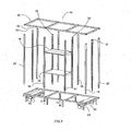
- FIG 3 is an exploded view of one preferred embodiment of cabinet 44.
- cabinet 44 is comprised of lower shelve 46 and upper shelf 48.
- Central control unit 40 is disposed between shelves 46 and 48, and also between standards 50 and 52 and supports 54 and 56.
- central control unit 40 is attached to standards 50 and 52 by means of slotted tabs (not shown) that engage rectangular openings 58 in the standards 50 and 52.
- upper frame 60 is removably connected to standards 50, 51, 52, and 53 as well as supports 54, 56, 57, 58, 59, 61, 62, and 63.
- lower frame 64 is also removably connected to standards 50, 51, 52, and 53 as well as supports 54, 56, 57, 58, 59, 61, 62, and 63.
- the fact that such frames are removably connected facilitates the ability of the apparatus 10 to be readily disassembled, moved through a standard doorway, and reassembled.
- cabinet 44 is comprised of means for raising and/or lowering the shelves 46 and 48 and the apparatus 10 (not shown in Figure 3 , but see Figures 1 and 2 ) disposed there between
- One may use conventional means known to those skilled in the art for effecting this movement.
- lower frame 64 is operatively connected to a pair of scissors jacks 66 and 68 that are adapted to move frame 64 in the direction of arrow 70 and/or 72.
- These scissor jacks are well known and may be activated by either mechanical means, electrical means, or pneumatic means.
- cabinet is comprised of a top panel 74 and a front facing panel 76.
- the cabinet 44 also is comprised of doors 78 and 80 which may be opened and closed. In the embodiment depicted in Figure 2 , door 78 is open and door 80 is closed.
- each of doors 78 and 80 comprise a glass face 79 and 81, respectively. It is also preferred that glass panes 83 and 85 be disposed on top of and beneath control unit 40.
- one or both of the doors 78 and 80 are located on the rear facing side 89 of the machine.
- the 86, 87 and 88 are preferably arranged in such a way as to allow the products 90 and 91 to be viewed from the customer (not shown) in a clear and easily recognizable manner.
- the customer can view the product labeling 92 and 93 in a normal reading orientation.
- the products 90 and 91 can be loaded into the trays 86, 87 and 88 directly from the front of the vending machine 10 when the doors 78 and 80 are opened.
- roller chain 98 is part of a 3-axis drive mechanism 100 (see Figure 4 ) that is illustrated in more detail in Figures 4 et seq.
- the 3-axis drive mechanism is preferably adapted to move a drive in the X, Y, and Z axes. These mechanisms are well known to those skilled in the art.
- Figure 4 illustrates a 3-axis drive mechanism 100, which comprises a vacuum pick mechanism 102 and a support rail apparatus 104.
- roller chain 82 and 122 are connected to the end caps 121 and 123 and to a reversible motor 118 which cause the support rail to move vertically in the Y axis as indicated by arrows 106 and 108.
- the support rail apparatus 104 is movably disposed on vertical rails 96 and 97 (see Figure 4 ) and is adapted to be moved thereon by chains 82 and 122.
- the roller chains 82/122 are preferred flexible drive means that, in combination with reversible motor 118 and controller 22 (not shown in figure 4 , but see Figure 1 ) to which the motor 118 is operatively connected, comprise a motion control device.
- a motion control device Any of the motion control devices known to those skilled in the art such as, e.g., the devices disclosed in United States patents 4,847,543 (motion control drive interface), 4,855,661 (motion control apparatus for induction motor), 5,267,604 (motion control system for horizontal continuous caster), 6,297,6212 (motion control coupling apparatus), 7,076,322 (system and method for satisfying move constraints when performing a motion control sequence), 7,194,321 (modular multi-axis motion control and driving system and method thereof), reissue patent 39,907 (tolerance based motion control system), and the like.
- the entire disclosure of each of these United States patents is hereby incorporated by reference into this specification.
- motors 118 and 154 are each operatively connected to controller 22 and can furnish such controller 22 information about the positions of support rail apparatus 104 and the pic motor 102.
- each of motors 118 and 154 are encoder motors. These motors are well known to those skilled in the art. Reference may be had, e.g., to United States patents 4,680,518 (servomotor velocity control method), 4,695,780 (servomotor velocity control method), 4,795,925 (servomotor velocity control method) and the like. The entire disclosure of each of these United States patents is hereby incorporated by reference into this specification.
- each of the motors 118 and 154 is a reversible motor.
- the pick mechanism 102 is is preferably connected to reversible drive motor 154 and drive belt 150 which allows the pick mechanism 102 to move horizontally in the X axis as indicate by arrows 110 and 112.
- the pick mechanism is capable of moving in the Z-axis as indicated by arrows 114 and 116 and is further described below.
- a telescoping vacuum pick mechanism 102 is disclosed.
- a vacuum pick mechanism such as a picker
- X-y carriage 28 and X motor 30 may be connected in a variety of ways such as by an endless chain which engages toothed sprockets (not shown) provided on both x-y carriage 28 and X motor 30. Movement of x-y beam 18 is similarly accomplished by providing Y motor 32 for driving Y axle 34. Y axle 34 has one gear 35 at each end thereof, enmeshed with toothed rack 37. The positions of x-y carriage 28 and x-y beam 18 are determined by X position sensor 36 and Y position sensor 38, respectively, which feed distance measurements to an automatic control system 40 located adjacent to freezer compartment 12 which governs and coordinates all the operations of the present invention. The preceding arrangement for positioning the x-y carriage 28 over the correct dispensable product may be referred to collectively as the x-y positioning means.”
- blower motor 42 is housed between machine cabinet 10 and freezer compartment 12. Blower motor 42 has connected thereto a flexible air hose 44, which air hose 44 is connected at its other end to x-y carriage 28 which comprises an air conduit 46.
- X-y carriage 28 has a picker guide tube 48 extending down therefrom which houses a longitudinally-compressible hose 50.
- Picker guide tube 48 has mounted on an outer surface thereof a z-origin sensor 51 for a purpose which will be more fully discussed hereinbelow.”
- Hose 50 connects at its upper end with air conduit 46 and has a picker head 52 at its lower terminus.
- Picker head 52 comprises a counterweight against sudden closed-end vacuum pressure and has a generally cylindrical upper portion 53 with a frustum-shaped lower end 55 for a reason which will be disclosed hereinbelow.
- a Z motor 54 mounted to x-y carriage 28 is attached to a Z reel 56 which has wrapped thereon two Z cables 58. Cables 58 are wound around Z reel 56 which is rotated by Z motor 54, and then pass over centering Z pulleys 60 which align cables 58 so they are equidistant from one another and parallel with the longitudinal axis of guide tube 48.”
- Claim 2 of United States patent 5,240,139 discloses: " 2. A vending apparatus in accordance with claim 1, wherein said package removing means comprises: a) a picker for contacting the package to be removed; b) x-y positioning means for horizontally positioning said picker over the package; c) z positioning means for selectively raising and lowering said picker above the package; d) constant air blower means for creating a constant negative air pressure, said air blower means being connected to said picker by an air hose; and e) sensing means for sensing contact between said picker and said package.”
- Apparatus for storing and selectively retrieving articles comprising a vertical array of storage locations each having a horizontal surface on which articles may rest and along which articles may be slid, a carriage mounted for movement horizontally and vertically across the face of the array so as to be selectively positionable at any one of the locations, and an arm mounted on the carriage and selectively extendable and retractable to engage and withdraw a selected article from a first one of said locations on to the car- riage, the carriage then being movable to another of said locations at which the arm may be extended to discharge the article from the carriage into said other location.”
- Claim 2 of PCT/GB 1004/002501 describes: "2. Apparatus according to Claim 1, wherein the arm comprises a telescopic suction tube.”
- Claim 5 of PCT/GB 1004/002501 describes: "5. Apparatus according to Claim 2, 3 or 4, wherein the carriage has mounted thereon a drum rotatable by a motor and carrying a flat flexible tape, the free end of which is attached to the free end of the tube whereby the tube may be selectively ex tended and retracted.”
- Claim 3 of PCT/GB 1004/002501 describes: "8. Apparatus according to any preceding claim, comprising an optical detec tor on the carriage for identifying the article in a storage location.”
- Claim 11 of PCT/GB 1004/002501 describes: "11. Apparatus according to any preceeding claim, wherein the array of storage locations comprises a delivery location from which an article may be manually retrieved.”
- Claim 12 of PCT/GB 1004/002501 describes: "12. A vending machine comprising apparatus according to Claim 9, located within a closed cabinet providing access only to said delivery location, selection means on the cabinet for sending an article selection signal to control means to indicate the choice of article to be vended by the machine, and payment means for receiving a payment in relation to the article and for sending a payment signal to the control means when the payment has been received, wherein the control means is arranged to control the movement of the carriage and the operation of the arm in response to receipt of the article selection and payment signals to deliver the selected article from the respective storage location to said delivery location.”
- Claim 13 of PCT/GB 1004/002501 describes: "13. A vending machine according to Claim 12, wherein the cabinet is provided with a transparent panel in one vertical face thereof, and the array of storage locations is positioned with the vertical face thereof opposite to that over which the carriage is mov able adjacent to the transparent panel, whereby the contents of all the storage locations are visible from outside the cabinet.”
- Claim 14 of PCT/GB 1004/002501 describes: "14. A vending machine according to Claim 13, comprising a door in the cabinet for the delivery location.”
- Claim 15 of PCT/GB 1004/002501 describe: "15. A vending machine according to Claim 14, wherein the door is provided with a lock controllable by the control means to release the door when the selected article has been delivered to the delivery location.”
- pick mechanism 102 is comprised of a comprises of a vacuum chamber 130, which is rigidly mounted to the carriage 132.
- the vacuum chamber 130 delivers negative air pressure from a vacuum source 131 to elastic suction cup 156.
- other vacuum sources such as, e.g., those disclosed in United States patents 6,148,902 (multiple die casting machines with single vacuum source), 6,315,524 (pump system with vacuum source), 6,585,492 (pump system with vacuum source), 6,830,416 (system and method for securing workpieces to a worktable of a CNC machining system utilizing a low level vacuum source), and the like.
- the entire disclosure of each of these United States patents is hereby incorporated by reference into this specification.
- the vacuum source provide at least 60 inches (150 cm) of water vacuum and, more preferably, at least 80 inches (200 cm) of water of vacuum.
- the vacuum chamber 130 is attached to a series of telescoping tubes 134, 135, 136, 137, 138, 139, 140.
- telescoping tubes known to those skilled in the art.
- the entire disclosure of each of these United States patents is hereby incorporated by reference into this specification.
- telescoping tube 134 is preferably rigidly affixed to the vacuum chamber 130, and the vacuum chamber 130 is connected to a vacuum source 131.
- the vacuum pick mechanism 102 is also comprised of means for controlling the vacuum so that one can vary the amount of vacuum supplied depending on whether, e.g., an article is attached or not attached to the suction cup 156. When an article is not attached to the suction cup 156, it is preferred not to have any vacuum applied. When no vacuum is applied, the controller 22 (which is operatively connected to the pick mechanism 102) knows that no article is attached. This feature is further described elsewhere in the specification.
- the entire disclosure of each of these United States patents is hereby incorporated by reference into this specification.
- a preferred suction control device (a vacuum pressure switch) is disclosed.
- the vacuum pressure switch 142 is connected to the vacuum chamber 130.
- a snap action or contact switch 144 is connected to the carriage 132 and has a lever 146 that remains in contact with the suction tube 140 when the tube is in the fully retracted position.
- a support plate 148 is rigidly attached to the end of suction tube 140 providing support when the tube is fully extended as described below. Without wishing to be bound to any particular disclosure, applicant believes that the tube without the support plate 148 could sag over the length of its extension causing a pick failure.
- the carriage 132 is operatively connected to a drive belt 150. Rollers 152 ride on the support rail 104.
- the drive belt 150 is attached to a drive reversible drive motor 154
- the telescoping tubes 135, 136, 137, 138, 139, and 140 are preferably connected to a friction drive to cause them to extend or retract.
- a friction drive to cause them to extend or retract.
- a motor-driven, telescoping antenna for automobiles comprising an electric motor having a rotatable armature; an extensible antenna rod passing through the center of the armature and slidable freely with respect thereto, a helically coiled spring (a) fixed to the bottom end of said antenna rod; a rotatable drive tube (d) attached to the bottom end of said armature and rotatable therewith; an angularly bent pin (b) fixed to the bottom end of said drive tube and having one horizontal arm extending between coils of said spring, and a vertical arm extending longitudinally through the center of the spring; said spring having bridges (h) extending between adjacent coils at each end thereof, said bridges being engaged by said pin (b) at the end of the linear travel of said spring during extension or retraction of the antenna, thereby causing said
- a motor 158 is affixed to the carriage 132 and connected to a friction drive roller 160 by means of gears 162,163,164,165 and, 166, drive shaft 168.
- a flat spring coil 170 is compressed between the friction drive roller 160 and an idler roller 172. The end of the flat spring coil 170 is rigidly connected to the end of tube 140. Also connected to the tube 140 is an elastic suction cup 156.
- the gears 162,163,164 and 165 cause the friction drive roller 160 to rotate imparting a friction drive force to the flat coil spring 170 and imparting a force on the end of the tube 140 causing it to move in a linear direction and telescope outwards increasing the length of the telescoping pick mechanism 102.
- the suction cup 156 is preferably a bellows suction cup.
- a bellows suction cup is disclosed, e.g., in United States patent 4,582,353 and in claim 1 thereof, which discloses: "1.
- a carton feeder located adjacent said magazine and transport conveyor for engaging flat folded cartons in said magazine, erecting said cartons and placing said cartons between said transport lugs, said carton feeder comprising: a channel-shaped element, having parallel legs, said legs being spaced apart approximately a distance L, at least one bellows suction cup mounted on said channel-shaped element and located between said legs, means connected to said suction cup for applying a vacuum to said suction cup, and means connected to said channel-shaped element for moving said channel-shaped element and suction cup between said magazine and said transport conveyor, said suction cup engaging a top wall of said carton and drawing said top wall and a portion of the side walls between the legs of said channel-shaped member to substantially erect the carton and deposit it between leading and trailing lugs of said transport conveyor;" and such suction cup is
- Bellows suction cups are also disclosed in United States patent 4,178,839 , the entire disclosure of which is hereby incorporated by reference into this specification. Reference may be had, e.g., to Figure 6 .
- Bellows suction cups are well known to those skilled in the art and are commercially available, e.g., from the Anver Corp. of 36 Parmenter Road, Hudson, Ma. 01749. One may use, e.g., bellows suction cups that have from about 1.5 to about 2.5 bellows and a diameter of from about of from about 0.7 to about 2.0 inches; suitable bellows suction cups available from Anver Corp. include model B1.5-25-SIT, B1.5-20-SIT, B-1.5-42-SIT.
- the bellows suction cup is preferably made from translucent material. It is preferred that the bellow suction cup comprise or consist essentially of silicone rubber. As is known to those skilled in the art, silicone rubber is usually a long-chain dimethyl silicone which will flow under heat and pressure but can be vulcanized by cross-linking the linear chains.
- the bellows suction cup has a Durometer hardness (Shore A) of less than about 45.
- the telescoping tubes such as tube 135, be comprised of a metal alloy material 211 with a coating 213 disposed on top of such material.
- the metal alloy material is preferably a half hard brass that has a thickness of from about 0.01" (0.03 cm) to about 0.04." (0.1 cm)
- several of the tubes have a thickness of about 0.014" (0.036 cm), and several of the tubes have a thickness of 0.029" (0.074 cm).
- the coating disposed on top of the half-hard brass have a thickness of from about 0.00005 (0.00013 cm) to about 0.001 inches (0.003 cm).
- the coating is a wear-resistant material such as a chromium plating.
- chromium plating is widely used where extreme hardness or resistance to corrosion is required, and it utilizes plates up to about 0.05 inches (0.13 cm).
- the telescoping tubes are comprised of means for preventing the interior section of the tube from becoming disengaged from the exterior section of the tube.
- tube 135 is disposed within tube 134; tube 136 is disposed within tube 135; tube 137 is disposed within tube 136; tube 138 is disposed within tube 137; tube 139 is disposed within tube 138; and tube 140 is disposed within tube 139.
- the overall assembly depicted in Figure 1 is telescoping tube 205.
- Each of the tubes 134 et seq. has a length that preferably is less than about 4.5 inches (11.4 cm).
- the overall length of the telescoping tube assembly 205 (see Figure 10 ), when collapsed, is preferably less than about 5 inches (13 cm); the extended length is at least about 22 inches (56 cm); and the ratio of the extended length to the collapsed length is at least about 4.0.
- a pick mechanism is illustrated, e.g., in Figures 4 and 5 of International publication WO 2004/114233 .
- the suction tube 15 is attached to a series of telescoping tubes 16a-16e.
- Tube 16a is rigidly affixed to the table 11 and connected to the vacuum suction tube 15.”
- the tubes 134, 135,136, 137, 138, 139, 140 have external stepped rings 174, 175, 176, 177, 178 and 179 rigidly attached to them.
- the tubes also have an external stepped ring 180, 181, 182, 183 and 184.
- the rings external step rings 174, 175, 176 177, 178 and 179 will eventually contact the internal stop tings 180,181, 182, 183 and 184 causing the tubes to extend outwards.
- the stop rings 186, 187, 188, 189 and 190 also prevent the tubes from over travel in the reverse mode and prevent concentric disengagement of the tubes. Furthermore the tubes 134, 135, 135, 136, 137, 138, 139 and 140 are contracted in such a way as to provide an air path for providing negative pressure (vacuum) at the elastic suction cup 156.
- the telescoping tubes 134, 135, 135, 136, 137, 138, 139 and 140 are shown in a fully extended position. It should be noted that the telescoping tubes 134, 135, 135, 136, 137, 138, 139 and 140 can be extended to any distance between the fully retracted position and the fully extended position, thereby allowing for the retrieval of a product or multiple products in any of the storage locations in the array.
- the support plate 148 is shown making contact with a product tray 86, 87and 88 effectively keeping the extended height of the suction cup 156 at the same height as if in the fully retracted position.
- the articles 90, 92 and 93 are positioned directly behind the glass face 79 and 81 at the front of the machine, and the pick mechanism 102 is positioned at the rear of the machine to pull the articles off the trays 86, 87 and 88 from the rear of the line of articles on the tray, so that the front article remains visible through the window to assist the customer in selecting the desired article.
- the articles picked from the tray are then delivered to the product delivery 42, as hereinafter described, for retrieval at the front of the machine.
- one possible vacuum source comprises of a vacuum fan motor 212 and a vacuum fan 214 contained in a casing 216, which is rigidly mounted on the pick mechanism 102.
- a suction tube 218 extends between the casing 216 and the vacuum chamber 130 in turn connected to the telescoping tubes 134-140. It may be also apparent to those skilled in the art, that the vacuum source may reside separately form the pick mechanism 102 and be connected to the pick mechanism by a standard vacuum hose.
- Figures 14 and 15 illustrate an apparatus and a process for moving the suction cup 156 relative to the carrier tray 206, to allow for optimum product attachment on the vertical axis.
- a reversible motor 286 is rigidly connected to casing 216 and attached to arm 287.
- a series of slots 290 are in the casing 216 and receive pins 292 on the vacuum chamber 130.
- Figures 14 and 15 only show one side of the apparatus; however, corresponding slots and pins are located on the opposite side.
- the controller 22 turns the motor 286 causing the arm 287 to contact the bottom of the vacuum chamber 130 and allowing it to raise or lower depending on the need.
- the relative distance is indicated by arrows 294 and 296.
- the lock controllable product delivery door 42 comprises a frame 248, a rotating drum 250, axially mounted bushings 252 pivotally mounted to the frame 248 for means of rotating the drum 250, a worm gear 254 driven by a motor 256, two optical sensors 258 and 260, and guide walls 262 and 264.
- the drum 250 is operatively connected to the controller 22. It may be caused to rotate by conventional means.
- a worm gear 254 is engaged with a worm wheel 266, which is rigidly connected to a spur gear 268, the spur gear being engaged with a driven gear 270.
- the driven gear 270 is rigidly mounted to the drum 250.
- An actuator is rigidly mounted to the driven gear 270 and makes contact with one of two switches 274 and 276 when the drum is fully opened or fully closed.
- the worm gear 254 provides the locking force required to keep the drum 250 locked in the closed or open position.
- the vacuum tubes 234-240 extend to push the article 90 into the rotating drum 250 in the direction of arrow. If one of the optical sensors 258 or 260 is blocked by article 90, a signal is sent to the controller causing the motor 254 to rotate in the direction of arrow 280 to an open configuration and open the drum 250. When the drum 250 has rotated to the open configuration, the article can be retrieved from the drum through an opening 282. When the article 90 is removed, the sensor 258 or 260 is unblocked and the controller causes the motor 254 to reverse, closing the drum 250 to a full locked position. A sensor array 285 is mounted to the frame 248 so as to allow scanning of the product 90 when positioned in the drum 250.
- the sensor array may use optical scanning technology such as bar code scanning or may us radio frequency-scanning method known as RFID.
- the product identification typically is printed directly on the product 90 or embedded into an RFID tag on the product 90, can then be recognized by the machine controller 22. This information can be used for inventory control and insurance that the correct product has been delivered.
- the assembly described can determine whether, in fact, the article has actually been delivered to a customer. If it is determined that a delivery has not occurred, the machine controller 22 will not charge the customer and can enter into a "recovery mode" or an "out of service condition.” This feature is described in more detail in the process section of the case.
- the device 10 may be used with conventional display and storage systems.
- display and storage disclosed in United States patents 4,938,364 (presentation display storage system), 5,411,146 (shelving display and storage system for bulk container items), 6,227,388 (display and storage system), 6,460,279 (custom display and storage system), and the like.
- United States patents 4,938,364 presentation display storage system
- 5,411,146 superimposed display and storage system
- 6,227,388 display and storage system
- 6,460,279 custom display and storage system
- FIG 19 is a schematic view illustrating one preferred display and storage system 300 that that may be used in conjunction with device 10.
- Such display and storage system 300 is comprised of a display glass 81 and a support shelf 86; the support shelf may be similar to those used in used in cooler, freezer or vending machine as normally used in a point of sale location.
- a multiplicity of sidewalls 302 define a channel 303 in which objects can be placed.
- a bristle brush 304 is preferably rigidly attached to the sidewalls 302. Sample products 306 and 308 are placed between opposing sidewalls 302 and opposing bristle brushes 304.
- Figure 20 is close up view of the apparatus 300.
- the opposing bristle brushes 304 make contact with products 306 and 308 and allow them to stand upright in the shelf.
- applicant believes that such bristle brushes are especially adapted to maintain product 306 and 308 in a standing position but to readily facilitate their removal form the support shelf 86.
- bristle brushes are well known. Reference may be had, e.g., to United States patents 3,384,915 (multiple compliant bristle brush), 3,500,491 (bristle brush), 5,327,608 (moving bristle brush), 6,968,848 (retractable bristle brush), and the like. The entire disclosure of each of these United States patents is hereby incorporated by reference into this specification.
- the bristles brushes 302 are preferably made of a flexible material allowing them to conform to the shape of the objects 306 and 308.
- the bristles brush 304 are of sufficient strength to hold the objects 306 and 308 in an upright position, allowing the point of sale customer to see them in a normal viewing orientation.
- the rear object 307in the channels can be retrieved by means of any robotic method.
- the remaining products 306 and 308 in the channels will remain in their position.
- Figure 21 shows the sidewalls 302 disengaged from the shelf 86.
- a series of slots 310 in the shelves and a series of tabs 312 on the sidewalls align in such a way as to allow the sidewalls to be moved to various slots 310 on the support shelf 86 allowing the bristle brushes 304 to be adjusted for best resistance on the product 306 and 308 and allowing a variety of product widths to be used.
- the sidewalls 302 can be used without the Bristol brushes 304 for any product not requiring side resistance to stand upright.
- a shelf 314 is comprised of a frame 316 and a glass plate 318.
- the frame 314 has a series of slots 320 orientated to accept the sidewall 322.
- the frame 316 can accept any number of sidewalls 322.
- the glass plate 318 allows light to pass through the shelves 314 or a series of shelf's enabling the products 36 to be highly visible.
- Figure 23 illustrates a shelving assembly 317 that is comprised of a light source 324 that is rigidly attached to the bottom of the shelf 314.
- the light source 324 can illuminate through the glass plate 318.
- the light source can provide, e.g., fluorescent, incandescent, or LED lighting; in one embodiment, it provides daylight.
- the light source 324 can be used with shelf 86 as described elsewhere in this specification to cause products below it to be illuminated.
- Figure 24 show a shelving assembly 319 that is comprised of a shelf 86 with an array of hooks 326 attached below it.
- the hooks 326 can be used hang an array of products 328 to it.
- a refrigeration module 350 may be disposed in device 10 behind either door 78 and/or door 80.
- the refrigeration unit 350 may be disposed on top of lower frame 64, beneath upper frame 60, between supports 54 and 58, and between standards 50 and 53.
- the refrigeration module 350 is comprised of a multiplicity of insulated panels that preferably include side panels 352 and 354, a top panel 356, and a bottom panel 357; the module also includes a series of shelves 358.
- the refrigeration module preferably includes a refrigeration deck 368.
- These refrigeration decks are well known. Reference may be had, e.g., to United States patents 4,781,310 (beverage dispenser), 4,801,048 (beverage dispenser), 5,335,988 (foil access cover for refrigeration deck), 6,581,389 (merchandiser using slide-out stirling refrigeration deck), and the like. The entire disclosure of each of these United States patents is hereby incorporated by reference into this specification.
- the shelves 358 are preferably comprised of a horizontal frame 360 that has a reversible motor 362 rigidly attached to it.
- the motor 364 is connected through a link 364 to a hinged panel 366.
- the hinged panel 366 is connected to the frame 360.
- the controller 22 causes the motor 362 to rotate and open the panel 366 exposing the product to the ambient environment and allowing the pick mechanism 102 to actively capture the product and deliver to the end user.
- Refrigerated air can be delivered through any of the four side panels 352, 353,354, 355, top panel 356 or bottom panel 357.
- an automatic bagging station and a beverage lid placement station 400 is comprised of hot/cold beverage fill mechanism 402, a cup lid mechanism 404 and a bagging station 406.
- the automatic bagging station and a beverage lid placement station 400 can be easily adapted to fit into the same style of cabinet 44 as described above.
- a bagging station 406 is comprised of a bag storage bin 408, a vacuum bag pick manifold 410, and a vacuum bag-expanding manifold 412.
- the bag storage bin 408 comprises an elevator 414 that holds empty folded bags in storage.
- the bag pick manifold 410 is mounted on a linear transport 414 and fixed in such a way as to rotate from vertical to horizontal.
- the bag pick manifold 410 is operatively connected to a vacuum source.
- the bag pick manifold 410 rotates horizontally and makes contact with the upper most bags 407 in the bag storage bin and effectively seals the bag to the manifold 410 by vacuum pressure.
- the manifold 410 then rotates vertically and moves linear until the bag 407 makes contact with the bag expanding mechanism 412, which uses the same vacuum sources as the bag pick manifold 410.
- the bag pick manifold 410 then reverses causing the bag 407 to expand to an open position.
- the bag 407 When the bag 407 is in the open position it can receive product from a chute or other means as described below.
- the door 416 then opens to allow the customer to obtain their products. Multiple items can be place in the expanded bag prior to delivery.
- a cup carousel 418 common to those skilled in that art drops a cup 420 onto a rotating cup transport 422.
- the rotating cup transport 422 then rotates the cup 420 to a fill station 424 where either a cold or hot beverage is dispensed into the cup 420.
- the cup 420 then further rotates on the cup transport 422 and stops at a lid placement station 426.
- a cup lid mechanism 428 then picks a lid 430 from the lid storage carousel 432 and places the lid 30 onto the cup 420.
- a cup gantry mechanism 434 then lifts the cup, with the lid 430 in place the cup gantry 434 lifts transports the cup it to the bag station 406.
- the cup gantry 34 then lowers the cup 420 into the expanded bag 407.
- a door 416 then opens and allows the customer to take the filled beverage cup 420. After the cup 420 is removed the door 436 closes and waits for the next cycle to begin.
- an automatic bagging station and a beverage lid placement station 400 is comprised of hot/cold beverage fill mechanism 402, a cup lid mechanism 404 and a bagging station 406.
- the automatic bagging station and a beverage lid placement station 400 can be easily adapted to fit into the same style of cabinet 44 as described above.
- a bagging station 406 is comprised of a bag storage bin 408, a vacuum bag pick manifold 410, and a vacuum bag-expanding manifold 412.
- the bag storage bin 408 comprises an elevator 414 that holds empty folded bags in storage.
- the bag pick manifold 410 is mounted on a linear transport 414 and fixed in such a way as to rotate form vertical to horizontal.
- the bag picks mechanism 410 and is operatively connected to a vacuum source.
- the bag pick manifold 410 rotates horizontally and makes contact with the upper most bags 407 in the bag storage bin and effectively seals the bag to the manifold 410 by vacuum pressure.
- the manifold 410 then rotates vertically and moves linear until the bag 407 makes contact with the bag expanding mechanism 412, which uses the same vacuum sources as the bag pick manifold 410.
- the bag pick manifold 410 then reveres causing the bag 407 to expand to an open position.
- the bag 407 When the bag 407 is in the open position it can receive product from a chute or other means as described below.
- the door 416 then opens to allow the customer to obtain their products. Multiple items can be placed in the expanded bag prior to delivery. Alternatively, multiple bags may be delivered as a result of only one payment, each of which may contain one or more items.
- Figure 31 is a block diagram of one preferred vending machine system 10.
- vending machine refers to any apparatus that stores and dispenses one or more articles.
- one or more of the devices depicted in Figure 31 and/or the processes depicted in Figure 31 and/or the software used in conjunction with Figure 31 may be used to modify the devices and processes depicted in such prior art vending machines as those described in United States patents 3,653,480 (automatic vending system), 3,935,933 (automatic article vending machine), 4,051,978 (merchandising compartmenting arrangement for an automatic vending machine), 4,319,698 (automatic cup drink vending machine), 4,428,828 (goods discharge mechanism and goods storage and discharge system of automatic vending machine), 4,600,094 (automatic vending machine with rotational dispensing function), 4,636,963 (control system for automatic vending machine), 5,154,272 (controller for an automatic vending machine), 5,238,097 (serpentine-type merchandise storing and
- vending machine system 10 is comprised of one or more vending machine controllers (such as, e.g., 22 and the graphical interface 29. Furthermore, it is preferred to additional control devices such as, e.g., P/C 244; these additional devices will be described elsewhere in the specification.
- vending machine controllers such as, e.g., 22 and the graphical interface 29.
- additional control devices such as, e.g., P/C 244; these additional devices will be described elsewhere in the specification.
- the vending machine controller 22 may be any of the vending machine controllers conventionally used for vending machines.
- the controllers described in United States patents 5,154,272 controller for an automatic vending machine
- 5,197,588 controller for vending machine
- 5,595,869 vending machine controller and system
- 6,839,775 method and apparatus for vending machine controller configured to monitor and analyze power profiles for plurality of motor coils to determine condition of vending machine
- the entire disclosure of each of these United States patents is hereby incorporated by reference into this specification.
- a vending-machine controller comprising: a programmable processor controlling operation of the vending machine; a first serial port connected to the programmable processor; an arbitrator operable in a hunt mode to monitor an input from each of at least two serially-communicating devices, respectively, to determine that a communication session is being initiated by one of the serially-communicating devices if activity is present upon an input, and to connect the first serial port of the programmable processor to the serially-communicating device that first initiates a communication session; and a second serial port configured as one of a multi-drop bus interface and a VCCS bus interface for connecting the programmable processor to a multi-drop bus or a VCCS bus, respectively.”
- controller 22 is an embedded controller.
- embedded controllers are well known and are described, e.g., in United States patents 6,948,098 (circuits and methods for debugging an embedded processor and systems using the same), 6,976,136 (flash memory protection scheme for secured shared BIOS implementation in personal computers with an embedded controller), 6,859,886 (IO based embedded processor clock speed control), 6,985,441 (intelligent embedded processor enabled mechanism to implement RSVP function), 7,139,077 (using an embedded processor to implement a finite state machine), 7,281,228 (configurable memory system for embedded processors), 7,283,549 (method for increasing the transmit and receive efficiency of an embedded ethernet controller), 7,340,596 (embedded processor with watchdog timer for programmable logic), 7,350,178 (embedded processor with watchdog timer for programmable logic), and the like.
- the entire disclosure of each of these United States patents is hereby incorporated by reference into this specification.
- an embedded controller is a device that performs embedded control.
- the I/O system is not connected to an external PC but, instead, the processor running the system is actually incorporated into the I/O chassis itself.
- the entire disclosure of each of these United States patents is hereby incorporated by reference into this specification.
- FIGs 32 , 33 , and 34 A schematic of a preferred control board is illustrated in Figures 32 , 33 , and 34 which describe, respectively, a preferred microcontroller 22 ( Figure 32 ) an onboard power supply unit 600, a serial I/O unit 602, LED outputs 604, an MDB (multidrop bus) interface) 606, an I2C bus 608, spare I/O's 610, 612, and 614, ( Figure 33 ), and three-axis drive mechanism outputs 616, 618, and 620, ( Figure 34 ).
- embedded processor 22 is comprised of a multiplicity of inputs--outputs (I/O's) that allow processor 22 to communicate with other circuits and/or other components of the circuit. It is preferred that the embedded processor contains at least 40 such I/O's and, preferably, at least 50 such I/O's. In one embodiment, the processor 22 contains 60 such I/0's.
- I/O's inputs--outputs
- Controllers comprised of a multiplicity of I/O's are well known to those skilled in the art. Reference may be had, e.g., to United States patents 3,654,617 (microprogrammable I/O controller), 4,293,924 (programmable controller with high density intelligent I/O interface), 4,504,927 (programmable controller with expandable I/O interface circuitry), 4,510,565 (programmable controller with intelligent positioning I/O modules), 5,778,236 (multiprocessing interrupt controller on I/O bus), 5,943,479 (method for reducing the rate of interrupts in a high speed I/O controller), 6,189,052 (On-chip i/o processor supporting different protocols having on-chip controller for reading and setting pins, starting timers, and generating interrupts at well defined points in time), and the like. The entire disclosure of each of these United States patents is hereby incorporated by reference into this specification.
- the embedded controller 22 is operatively connected to X-drive assembly 616, Y-drive assembly 618, Z-drive assembly 620.
- embedded controller 22 is preferably connected to a delivery door assembly 624 (see Figure 32B ), a liquid crystal display 626 (LCD) assembly (see Figure 32C ), an alpha-numeric keypad assembly 628 (see Figure 32D ), a vacuum release mechanism 630 (see Figure 32E ), a temperature sensor assembly 632 (see Figure 32F ), a clock 634 (see Figure 32G ), non-volatile RAM 636 (see Figure 32G ), a Y switch assembly 622 (see Figure 32H ) and an in circuit programming port 668.
- a delivery door assembly 624 see Figure 32B
- LCD liquid crystal display 626
- an alpha-numeric keypad assembly 628 see Figure 32D
- a vacuum release mechanism 630 see Figure 32E
- a temperature sensor assembly 632 see Figure 32F
- a clock 634 see Figure 32G
- non-volatile RAM 636 see Figure 32G
- Y switch assembly 622 see Figure 32H
- an in circuit programming port 668 an in circuit programming
- the apparatus is comprised of a controller assembly 22 that is preferably comprised of the circuitry illustrated, e.g., in Figures 32 , 33 and 34 .
- the controller assembly 22 is connected to the power supply unit 638 that, in the embodiment depicted, is connected via line 640 to the main power supply.
- the power supply 638 preferably delivers alternating current to onboard power supply 600.
- the onboard power supply 600 converts the alternating current fed to it (which is often 23 volts A.C.) to a multiplicity of direct current outputs.
- the power supply 638 also delivers alternating current via line 642 to vacuum source 131 (see Figure 5 ).
- Vacuum source 131 is connected to vacuum release circuitry 630 that is illustrated, e.g., in Figure 32E .
- the power supply 638 is also operatively connected to a refrigeration module 350 comprised of a refrigeration deck 368 (see Figure 25 ).
- the power supply 638 is connected via line 644 to a lower voltage power supply 646 that converts that 23 volt alternating current into direct current such as, e.g., 12 volt d.c.
- This direct current is fed to telemetry unit 648, printer 235, credit card reader 232, touch screen 28, coin acceptor assembly 230, note reader 228, automatic teller machine 238, and note changer 236.
- each of these components is operatively connected to, and controlled by, computer 244 which also is directly connected to power supply 638 by line 650.
- the computer 244 is linked to the controller 22. In the embodiment depicted, the computer is so linked by line 652. In another embodiment, not shown, the computer is linked by a wireless link.
- the computer is preferably linked to a serial port 602 (see Figure 33 )
- I2C also known as Inter-Integrated Circuit
- I2C is a multi-master serial computer bus that is used to attach lower-speed peripherals to a motherboard, embedded system, or cellphone.
- the I2C bus 608 is adapted to turn the alternating current power on and off to the refrigeration assembly 350 and the vacuum source 131.
- the controller 22 monitors certain conditions that dictate when such power is turned on and off. This monitoring may be effected by conventional means such as, e.g., by temperature sensor 658 (see Figure 32F ).
- temperature sensor 658 is operatively connected to control board 660 by means not shown in Figure 32F , but see Figure 35 .
- temperature sensor circuit 660 is connected to temperature sensor 658 by means of line 662.
- Vacuum sensor 144 is connected to vacuum switch 621 (see Figure 34C ) that, in turn, is connected to Z axis interconnect board 664; interconnect board 664 is connected to control panel 22a.
- an ultrasonic sensor 157 (see Figure 5 ) is also connected to Z-axis interconnect board 664.
- the graphical interface is comprised of any number of the following components: note reader 228, coin acceptor 230, credit card reader 232, closed user group card reader 234, a note changer 236, a automatic teller machine (ATM) 238 or any other form of payment and also can be set to a no-payment option.
- the communication system 220 can communicate with a selection keypad 240 and a selection information display screen 242 or can be linked directly by serial bus to a p/c 244.
- the personnel computer 244 can be used to manage all the transaction functions including incorporating a touch screen 28 for user the interface and can also receive and send information via wired telecom, wireless telecom, wifi, internet, or intranet communications.
- the information can include, machine conditions, number of vends, amount of stock, all accounting information.
- the personnel computer 244 can also receive and implement software via the same.
- the motion control system controls the movement of the 3-axis drive mechanism 100, the vacuum pick mechanism 102, the product delivery 42 and the refrigeration control 246 when required.
- the note reader 228, credit card reader 232, closed user group card reader 234 and coin acceptor/changer 230 may be controlled either by the controller 22 or the personnel computer 244.
- the controller 22 is capable of storing the product data pertaining to the amount of product in the machine, the cost of each product and the amount of product sold. This information can be stored locally in memory or transmitted by any on the above-described means to a remote location for inventory control purpose. It is also a preferred embodiment that the machine conditions be stored in memory and the data can also be transmitted by any of the above means to a remote location fro the purpose of dispatching a technician or alternately solving any issues with a supervisor at the machine.
- Figure 35 is a flow diagram of one preferred process 500 for vending articles.
- an article to be vended is selecting.
- Devices and processes for selecting articles are well known and are described, e.g., in United States patents 3,731,788 (article selecting device), 3,826,348 (article selection and separation apparatus), 4,436,474 (selecting articles from an array thereof), 5,564,894 (article selection and delivery method and apparatus), 6,415,952 (apparatus for carrying selected article to take-out window in automatic vending machine), and the like.
- the entire disclosure of each of these United States patents is hereby incorporated by reference into this specification.
- the selection process might be facilitated by the graphical interface 29 (see Figure 1 ), and by the screen (which preferably is a touch screen) 28.
- touch screens are well known and are described, e.g., in United States patents 5,564,974 (coin sorting system with touch screen device), 5,768,386 (method and system for encrypting input from a touch screen), 6,688,518 (wall mounted touch screen information system), 6,741,237 (touch screen), 7,079,118 (touch screen using echo location), and the like. The entire disclosure of each of these United States patents is hereby incorporated by reference into this specification.
- step 501 the consumer makes payment by inserted payment into the machine in step 501.
- payment making processes are well known to those skilled in the art are described, e.g., in United States patent 4,797,540 (payment making terminal device), 5,154,260 (method and system for automated processing of articles), 5,239,480 (automatic ticket dispensing system), 5,860,362 (newspaper vending machine with online connection), 6,796,491 (electronic payment system, payment apparatus, and terminal thereof), 6,882,983 (method and system for processing transactions), 7,014,106 (electronic payment system, payment apparatus, and terminal thereof), 7,021,531 (payment device), and the like.
- the entire disclosure of each of these United States patents is hereby incorporated by reference into this specification.
- MDB multi-drop bus
- the MDB is often used with vending machines.
- the entire disclosure of each of these United States patents is hereby incorporated by reference into this specification.
- Devices for effectuating point of sale purchases are well known and are described, e.g., in United States patents 5,866,890 (device and method for sequencing participation in a point-of-sale activity), 6,003,008 (point of sale device), 6,827,260 (system and methods for utilizing a point-of-sale system), 6,883,706 (point-of-sale bill authorization), 6,886,472 (systems and methods for deploying a point-of-sale device, 7,295,992 (method and system for delivering products and services to a point of sale location), and the like.
- the entire disclosure of each of these United States patents is hereby incorporated by reference into this specification.
- step 501 after payment has been made in step 501, it is authorized in step 502.
- Means for authorizing and/or confirming and/or verifying payment are well known to those skilled in the art. Reference may be had, e.g., to United States patents 5,819,239 (method of verifying proper payment of postage), 5,826,241 (computerized system for making payments), 6,012,399 (space efficient method of verifying electronic payments), 6,529,886 (authenticating method for an access and/or payment control system), 6,895,391 (method and system for secure authenticated payment on a computer network), 7,051,002 (universal merchant platform for payment authentication), and the like. The entire disclosure of each of these United States patents is hereby incorporated by reference into this specification.
- step 502 If the payment is not authorized in step 502 the process ends at step 503 and the software resets the graphical interface 29.
- the MDB 606 reads the value of the payment tendered and authorizes the purchase and delivery event(s).
- the MBD 606 will preferably hold the payment tendered in escrow until it has determined that the goods purchased have been delivered.
- the payment may be held in escrow by physical and/or electronics means.
- the note reader 228 see Figure 35
- the coin acceptor 230 may physically hold the monies tendered in escrow until directed to delivery such monies to a cash box 666 (see Figure 35 ).
- an inspection of the drum 42 will reveal whether the product has been delivered. After such inspection, and after verification that such product has been delivered, payment is deducted in step 538.
- the MDB 606 (or the computer 244) will deduct payment from the escrowed account.
- the controller 22 begins to retrieve the article in step 504.
- the software checks at step 505 that the home switch 115, home switch 113, and tube home switch 144 are in the correct state.
- the controller 22 then causes the 3-axis drive mechanism 100 to position the support rails 104 and the pick mechanism 102 in such a way as to align the pick mechanism 102 with the appropriate product 90. If the tube home switch 144 is not engaged the software then sets the machine out of service step 506. If the home switch 115 and home switch 113 are not in the correct state the controller 22 will attempt to move the 3-axis mechanism to set the switches 113 and 115 to the correct state.
- the software will then set the machine out of service in step 506. Moving the carriage 132 without the telescoping tubes 134-140 completely retracted major machine failure and potentially damage to the partially extended tubes 135-140.
- the telescoping pick mechanism 102 then is positioned as to retrieve a product 90 in any one of the arrayed product trays 86, 87 and 88.
- the telescoping pick mechanism 102 is then energized and caused to extend. If the pick mechanism 102 is not the correct location at step 509, the software then attempts top move the pick mechanism 102 t0 home position in step 510. Again the software checks to ensure the pick mechanism is ion the correct position at step 511. If the pick mechanism is in the correct position then the article retrieval will be retried in step 504, conversely if the pick mechanism is not in the correct portion the process ends at step 554.
- the motor 158 has been energized causing the tubes 134-140 to extend.
- the vacuum pressure switch 142 detects a pressure change when contact between the elastic cup 156 and the product 90 has been made. If the pressure vacuum switch 142 does not make contact within a defined period of time, the software causes the motor 158 to be reversed and retract the tubes, then returning the machine to its initial start position provided that the snap action switch 144 is engaged. If the snap action switch 144 is not engaged at this point the software will set the machine out of service as described above. If the pressure vacuum switch 142 does make contact within the defined period of time, then the pick head 102 is moved to its delivery position.
- step 514 the software than proceeds to step 197 and checks to see if a predetermined retry limit has not been exceeded, if the limit has been exceed the machine is set out of service step 526. If the retry limit in step 525 has not been exceeded the machine will retry the pick cycle starting at step 515 and repeat this process until achieving the predetermined limit at step 525 or until successful engagement of the product occurs at step 514.
- the software at step 514 determines that the vacuum switch 142 is on, the software causes the motor 158 to reverse and move the tubes 134-140 to their collapsed position as shown in Figure 5 and at step 552.
- the software determines at step 516 if the tube home switch 144 is closed. If the tube home switch 144 is not closed, the software then sets the machine out of service at step 517. If the tube home switch 144 is closed the software then causes the controller 22 to move the 3-axis drive mechanism to its home position at step 522.
- the home position as described earlier, is the position that the product 90 is offered to the delivery 42.
- the controller 22 will again attempt to seek and find the home position AT STEP 556 by looking for switches 113 and 115 to be engaged, If the switches are not engaged after a second attempt the controller 22 will set the machine out of service at step 558.
- the controller When switches 113 and 115 are confirmed engaged, the controller cause the z-axis motor 158 to run and extend the tubes 134-140 as shown in Figure 10 and step 528, pushing the product 90 through the delivery 42 (as shown in Figure 18 ).
- the software checks to see if the drum sensors 258 and 260 are engaged at step 529, if they are engaged the vacuum source 131, is then turned off and the motor encoder 158 runs in reverse to collapse the tubes 134 -140. If the tube home switch 144 is not engaged the software then sets the machine out of service at step 535.
- the controller runs drum motor 256 at step 536 causing the drum 250 to rotate and exposing the product 90 to the customer who can then retrieve the product 90.
- the software checks that the drum switch 276 is engaged at step 537. If the switch 276 is engaged at step 537, the software then confirms the drum 250 is open and the payment is deducted at step 538. The software then causes the drum 250 to close at step 539. If the switch at step 537 is not engaged, the software closes the drum at step 548 and then checks to see if the retry limit at step 549 has been exceeded. If the retry limit at step 549 has not been exceeded, the software will try to open the drum at step 536 in an attempt to satisfy the conditions at step 537.
- a number of retries can be set by software to allow for the drum 250 not to close at step 539.
- the software After checking that the drum sensors 258 and 260 are off at step 540, the software then checks the retry limit is checked at step 547, and if the retry limit at step 547 has been exceeded the machine is set out of service at step 550. If the retry limit at step 549 has not been exceeded the drum will attempt to open at step 536 and loop around until the conditions are satisfied.
- the software checks to see if the drum closed switch 274 is engaged and then resets the control panel at step 544 and end the process at step 545. If the drum switch is not closed at step 424, the software then sets the machine out of service at step 543.
- the pick head 102 normally rests directly behind the product delivery 42 when the machine is in an idle state.
- An x positions sensor 113 and a y position sensor 115 ensure that the pick head is located at the correct position.
- the distance is absolute to the controller 22 and recorded to the controller by encoder motor 118 and encoder motor 154.
- the controller 22 records the encoder counts again from the encoder motors 118 and 154, using that distance as reference.
- the pick head 102 can adjust its return position in the by referencing the signal given off by the two sensors 113 and 115, thereby ensuring accurate position for the completion of the vend cycle and the beginning of the next cycle.
- the pick head 102 delivers a product it moves this allow the machine 10 to expedite product 90 retrieval and delivery by averaging the distance traveled to and from the any product 90.
- the pick head 102 can be idled or positioned directly behind a product 90 that is the most popular to help expedite product retrieval and delivery.
- the controller 22 can also move the pick head 102 to s product 90 that has been selected and idle at that position while a credit card authorization is being made. After said authorization is completed the pick head 102 can then retrieve that product 90 and deliver it.
- a carrier tray 206 is rigidly mounted to the pick mechanism 102.
- a product 90 is shown on the carrier tray 206.
- a surface 208 on the product tray 86 provides a means of transferring the product 90 to the tray 86.
- the carrier tray 206 is horizontally in line with the tray surface 208 as shown in Figure 34 and has a slight offset gap 210 as shown in Figure 35 .
- There are many variations in the bottom of the product 90 causing slight variations in the alignment of surface 208 and carrier tray 206 so as to allow the product 90 to be pushed by tubes 134-140 very smoothly onto the surface 208 and not be dropped or tipped.
- the gap 210 can be set for individual products by software control, allowing for different gaps on product delivery to be used and therefore ensuring smooth (no-drop) product delivery.
- the delivery position can be at any location on the x-y array and is preferable to be located at a position for product retrieval by a person. The position can be optimized for disabled persons.
- a shelf 86 has products 90 placed on it.
- a carrier tray has a substantially extended member 298.
- the pick mechanism 102 is positioned effectively to have member 298 forms a barrier.
- the member 90 blocks product from falling off the tray 86.
- a video camera 117 is rigidly mounted to the pick head 102 and operatively connects to the controller 22.
- the controller is capable ofbroadcast the video signal from the camera 117 and displaying it on the touch screen 28 allowing the end user to see their product being pick, delivered and transported.
- Another feature of the camera 117 is that it can be used as a diagnostic tool when video images are viewed on the touch screen 28.
- the video image can also be accessed by remote means through he personnel computer244.
- the controller 22 can count down product to memory and know when a channel 303, such as the one shown in Figure 19 , is empty and reload it with product 90 from another channel 303.
- the memory of the controller 22 is capable of adjusting the price of the product 90. This feature of the process allows the machine 10 to look full of product.
- the product 10 does not need to be behind glass 79, 81, 83 or 85 and can reside behind an opaque surface anywhere in the operation plan of the 3-axis pick mechanism 100.
- the controller 22 is also capable of scanning the x-y plan of the machine 10 and mapping the shelf 86 positions and the position of the sidewalls 30. This allows the product positions top be stored into memory on the controller 22.
- Another feature is that an end user can enter multiple items through the graphical interface the machine 10 will treat them as a single transaction and deliver multiple products to the delivery 42 either one at a time or more than one before payment is deducted.
- a distance detection sensor 157 is mounted to the front of the pick head 102.
- the sensor can be either ultrasonic or optical in nature.
- the controller 22 raises the pick head 102 above the shelf 86 and is energized by means of the controller 22, the sensor 157 signals reflects off the last product 90 in the channel 303.
- the apparatus described in the European case generally relates to a device for storing and selectively retrieving articles and to automatic vending machines that utilize a vacuum type product pulling/pushing mechanism similar to the pushing/pulling mechanism described and illustrated in this case.
- the preferred vending machine of this invention is preferably comprised of robust over travel stops on the telescoping tube, a friction drive system, a flat coil spring extension/retraction member driven by the friction system, a simple pressure switch for monitoring the supply vacuum, a positional switch ensuring that the tube is fully retracted and at a known starting position, a tube support feature that eliminates variations in the suction cup horizontal height when extended and control software that allows for pick retries in the event of a loss of vacuum during the pick cycle.
- an apparatus for storing and selectively retrieving articles comprising a vertical array of storage locations each having a horizontal surface on which articles may rest and along which articles may be slid, a carriage mounted for movement horizontally and vertically across the face of the array so as to be selectively positionable at any one of the locations, the carriage having mounted thereon a telescopic suction tube, suction tube drive means associated with the tube for selectively extending and retracting the tube, and suction means connected to the tube whereby the tube can be extended to engage a selected article in a first one of said locations, the suction means being selectively operable to hold the article to the end of the tube as the tube is retracted, thereby withdrawing the article from said location and on to the carriage, the carriage then being movable to another of said locations at which the tube may be extended to discharge the article from the carriage into said other location, characterised in that the suction tube drive means comprises an elongate flat strip capable
- the strip is suitably a thin spring steel which can be rolled up on itself, but which when unrolled assumes a straight, semi-rigid form.
- a thin spring steel which can be rolled up on itself, but which when unrolled assumes a straight, semi-rigid form.
- An example of such a material is the tape in a steel tape measure.
- An alternative material would be a plastics tape having a shape memory such that it can be rolled or coiled, but unrolls straight with sufficient rigidity to drive and retract the suction tube and attached product, sliding the product over the surface within its location and on to the carriage, and sliding off the carriage and on to the surface of the delivery location. In this way, the suction tube will not have to carry the full weight of the product, but will simply have to overcome friction to slide the product.
- low friction surfaces are provided in these locations to assist in this process.
- the vacuum operated pick mechanism incorporates positive stops on the telescoping vacuum tubes and a friction drive mechanism for extending and retracting a coiled steel spring member.
- Still further improvements relating to the pick mechanism include the use of adjustable or self adjusting vacuum switch for product detection and a position switch to determine the proper start/stop location of the vacuum tubes.
- Further improvements include vertical support means to maintain the proper height of the vacuum tubes when they are extended, particularly in the full extension mode.
- control software that recognizes a vacuum loss and can retry the attempted product move.
- Still further improvements include a soft (no drop) delivery system that is capable of handling varying weight objects and control software to allow for smooth transition from the transfer surface to the delivery surface. The delivery of the product can be can be optimized for ergonomics, particularly for a physically disabled person.
- a vending machine with a cabinet which could, for example, form an addition to an existing shop front, with the rear of the cabinet being accessible from within the shop and the front of the cabinet facing into the street or shopping mall.
- the cabinet preferably includes a product display panel or window, which is transparent so that goods for sale by the machine may be viewed by customers in the street, a product selection and payment panel and a product delivery door.
- the front of the cabinet may be a door giving access to the interior of the cabinet for loading and maintenance purposes.
- the cabinet could alternatively be a freestanding cabinet in conventional manner, and that the front panel may in some circumstances be opaque, for example being formed of steel for additional security for the contents of the machine.
- the product selection and payment panel may include a display screen, for example a liquid crystal display (LCD) screen which may be touch sensitive screen to to permit selection of displayed options by the customer.
- the payment means included in the machine may be, for example, a conventional coin mechanism, a note acceptor, a credit card terminal, or any combination of these.
- the vending machine of this invention and directly behind the transparent product display panel resides a series of product trays that generally have a plurality of products stored on them.
- the trays are arranged in such a way as to allow the products to be viewed from the customer in a clear and easily recognizable manner.
- the product labelling can be viewed in a normal reading orientation by the customer.
- the products can be loaded into the trays directly from the front of the vending machine when the front door is opened.
- the vending machine of this invention preferably comprises a product pick mechanism that, in one aspect thereof, comprises an x-y drive mechanism.
- x-y drive mechanism preferably is comprised of a fixed vertical rail and a horizontal rail mounted to slide relative to the vertical rail.
- a motorized elevator preferably creates motion in the y or vertical direction, and a motorized carriage is mounted on the horizontal rail for creating motion in the x or transverse direction.
- a telescoping vacuum pick mechanism Preferably attached to the carriage is a telescoping vacuum pick mechanism.
- This mechanism preferably is comprised of a vacuum chamber which is rigidly mounted to the carriage.
- the vacuum chamber is attached to a series of telescoping tubes.
- One of such tubes is rigidly affixed to the vacuum chamber, and the vacuum chamber is connected to a vacuum source.
- a vacuum pressure switch is preferably connected to the vacuum chamber.
- a snap action or contact switch is connected to the carriage and has a lever that remains in contact with the suction tube when the tube is in the fully retracted position.
- a support plate is rigidly attached to the end of suction tube and provides support when the tube is fully extended.
- a motor is affixed to the carriage and connected to a friction drive roller by means of gears and a drive shaft.
- a flat spring coil is preferably compressed between the friction drive roller and an idler roller. The end of the flat spring coil is rigidly connected to the end of the tube.
- Also connected to the tube is an elastic suction cup.
- the gears cause the friction drive roller to rotate, thereby imparting a friction drive force to the flat coil spring and imparting a force on the end of the tube, causing such tube to move in a linear direction and telescope outwards increasing the length of the telescoping pick mechanism.
- the telescoping tubes preferably have external stepped rings rigidly attached to them. As the tubes extend, these externally stepped rings cause the tubes to move in a linear manner to a limited extent, as is described elsewhere in this specification. However, when the motor is reversed, forces are then applied in the opposite direction, thereby causing the tubes to collapse.
- stop rings are rigidly attached to the telescoping tubes.
- the stop rings impart a force to the adjacent tube causing that tube to be pulled back.
- the stop rings also prevent the tubes from over travel in the reverse mode and prevent concentric disengagement of the tubes.
- the telescoping tubes are contracted in such a way as to provide an air path for providing negative pressure (vacuum) at the elastic suction cup.
- the telescoping tubes can be extended to any distance between the fully retracted position and the fully extended position, thereby allowing for the retrieval of a product or multiple products in any of the storage locations in the array.
- a support plate makes contact with a product tray, effectively keeping the extended height of the suction cup at the same height as if in the fully retracted position.
- the articles to be vended are preferably positioned directly behind the window at the front of the machine, and the pick mechanism is positioned at the rear of the machine to pull the articles off the tray from the rear of the line of articles on the tray, so that the front article remains visible through the window to assist the customer in selecting the desired article.
- the articles picked from the tray are then delivered to the delivery location for retrieval at the front of the machine.
- a customer would normally select a product by using the panel.
- the controller and its associated software checks that the snap action switch is engaged. If it is engaged, the drive mechanism positions the table in such a way as to align the telescoping vacuum pick mechanism with the appropriate product.
- the controller then sets the machine out of service. Moving the carriage without the telescoping tube in the completely retracted position would cause major machine failure and potentially damage the partially extended tubes.
- the telescoping vacuum pick mechanism then is positioned as to retrieve a product in any one of the arrayed product trays.
- the telescoping vacuum pick mechanism is then energized and caused to extend.
- the motor has been energized causing the telescoping tubes to extend.
- the vacuum pressure switch detects a pressure change when contact between the elastic cup and the product has been made. If the pressure vacuum switch does not make contact within a defined period of time, the software causes the motor to be reversed and retract the tubes, then returning the machine to its initial start position provided that the snap action switch is engaged. If the snap action switch is not engaged at this point the software will set the machine out of service as described above.
- the carriage is moved to its delivery position. If the pressure switch is not detected, the controller/software then checks to see if a predetermined retry limit has not been exceeded. If the limit has been exceeded, the machine is set out of service. If the retry limit has not been exceeded, the machine will retry the pick cycle repeat this process until achieving the predetermined limit.
- a carrier tray is rigidly mounted to the carrier.
- a surface on the product tray provides a means of transferring the product to the tray.
- the carrier tray preferably is horizontally in line with the tray surface and has a slight offset.
- a gap can be set for individual products by software control, allowing for different gaps on product delivery to be used and therefore ensuring smooth (no-drop) product delivery.
- the delivery position can be at any location on the x-y array and is preferably located at a position for product retrieval by a person.
- the vacuum source preferably consists of a vacuum fan motor and a vacuum fan contained in a casing that is rigidly mounted on the carriage.
- a suction tube extends between the casing and the vacuum chamber that, in turn, is connected to the telescoping tubes.
- the main machine control components of the vending machine comprise a control board comprised of a communication system, a payment system, and a motion control system.
- the payment system is comprised of at least one of the following: a note reader, a coin acceptor, a credit card reader. a closed user group card reader, 58 or any other form of payment; and it also can be set to a no-payment option.
- the communication system preferably can communicate with a selection keypad and a selection information display screen, or it can be linked directly by serial bus computer.
- the computer can be used to manage all the transaction functions including incorporating a touch screen for using the interface, and it can also receive and send information via wired telecom, wireless telecom, wifi, internet, or intranet communications.
- Such information can include, e.g., machine conditions, number of vends, amount of stock, accounting information, etc.
- the computer can also receive and implement software.
- the motion control system controls the movement of the carriage, the pick arm movements and vacuum, the door movement and refrigeration control if required.
- the vending machine comprises a lock controllable door that, in turn, comprises a frame, a rotating drum, axially bushings pivotally mounted to the frame for rotating the drum, a worm gear driven by a motor, two optical sensors, and guide walls.
- the worm gear is is engaged with a worm wheel that is rigidly connected to a spur gear; the spur gear is engaged with a driven gear; and the driven gear is rigidly mounted to the drum.
- an actuator is rigidly mounted to the driven gear and makes contact with one of two switches and when the drum is fully opened or fully closed.
- the worm gear provides the locking force required to keep the drum locked in the closed or open position.
- a signal is sent to the controller causing the motor to rotate and open the drum.
- the drum rotates, the article can be retrieved from the drum.
- the sensor is unblocked and the controller causes the motor to reverse, closing the drum to a full locked position.
Landscapes
- Physics & Mathematics (AREA)
- General Physics & Mathematics (AREA)
- Vending Machines For Individual Products (AREA)
- Control Of Vending Devices And Auxiliary Devices For Vending Devices (AREA)
Abstract
Description
- This invention relates to an apparatus and process for storing and selectively retrieving articles, and to a vending machine incorporating such apparatus and process.
- Until recent years most of the mechanisms used in various dispensing machines relied on fixed pitch spiral or fixed pitch conveyor delivery systems. Individual product selections required an individual mechanism for each product, consisting of a powered spiral or a powered segmented conveyor. Such machines suffer from a number of disadvantages, such as low volumetric efficiency of product density due to the fixed pitch nature of the spiral, physical damage to the products caused by forces induced by the spiral, and physical damage to the product caused by dropping the product to a delivery compartment.
- An additional disadvantage to most vending machines is that the machines take a long time to load and must be loaded from the rear of the product tray which is the furthest distance from the door opening. Fixed pitch type delivery systems require that each individual unit of product be placed into its respective slot or position for delivery, further slowing and complicating the loading process.
- It is conventional that most vending machines that have a visible front door to view the product require that the product be placed some distance behind the glass partition of the door, thereby limiting the clarity of the products to be selected by the customer. Machines that are low on product appear unappealing to potential customers.
- Most vending machines do not have a way to confirm that the product the customer has selected is the same product delivered to the customer. This is a disadvantage to the customer as well as the vending machine operators. It can lead to accounting errors as well as fraud. For example, some machine operator are subsidized by large corporate brands and are obligated to stock the contractually agreed brands. If the operator substitutes non-branded products for the contracted branded products, this can lead to reduced revenue for the corporate brand as well as a breach of contract.
- It is an object of this invention to provide an improved apparatus and process for vending goods.
- According to an aspect of the invention there is provided an apparatus for moving an article comprising a first telescoping tube movably connected to a second telescoping tube, a suction cup connected to said first telescoping tube, and a drive assembly connected to said first telescoping tube.
- Preferably said suction cup is a bellows suction cup.
- Preferably said bellows suction cup is comprised of from about 1.5 to about 2.5 bellows and has a diameter of from about 0.7 to about 2.0 inches.
- Preferably said bellows suction cup had a Durometer Shore A hardness of less than about 56.
- According to an aspect of the invention there is provided a vending machine comprised of the apparatus according to the first-recited aspect.
- According to an aspect of the invention there is provided an apparatus for moving an article comprising a first telescoping tube movably connected to a second telescoping tube, and a third telescoping tube movably connected to said second telescoping tube, wherein said first telescoping tube is connected to a suction cup, wherein said apparatus is also comprised of a drive mechanism connected to said first telescoping tube, and wherein (a) said first telescoping tube is comprised of a stop for limiting the motion of said second telescoping tube within said first telescoping tube, and said second telescoping tube is comprised of a stop for limiting the motion of said third telescoping tube within said second telescoping tube.
- Preferably said suction cup is a bellows suction cup that is comprised of from about 1.5 to about 2.5 bellows.
- Preferably each of said first telescoping tube, said second telescoping tube, and said third telescoping tube is comprised of a substrate and a coating disposed on said substrate.
- Preferably said substrate consists essentially of a metal alloy material.
- Preferably said metal alloy material is a half hard brass, and wherein said substrate has a thickness of from about 0.01 to about 0.04 inches.
- Preferably said coating has a thickness of from about 0.00005 to about 0.001 inches.
- Preferably said coating consists essentially of a water-resistant material.
- Preferably said water resistant material is chromium plating.
- According to an aspect of the invention there is provided a apparatus for picking up an article comprised of a suction cup, an arm connected to said suction cup, and a friction drive assembly connected to said arm for moving said arm.
- Preferably said apparatus is adapted to move said arm in the X axis, the Y axis, and the Z axis.
- Preferably said arm is comprised of a hollow center portion.
- Preferably a vacuum source is connected to said hollow center portion of said arm.
- Preferably the apparatus is comprised of means for expanding said arm.
- Preferably the apparatus is comprised of means for retracting said arm.
- Preferably said friction drive assembly is comprised of motor connected to a friction drive roller.
- Preferably said friction drive roller is connected to a spring coil.
- Preferably said spring coil is a flat spring coil.
- Preferably said spring coil is compressed between said friction drive roller and an idler roller.
- Preferably said spring coil is connected to said arm.
- According to an aspect of the invention there is provided an apparatus for storing and selectively retrieving articles, comprising a vertical array of storage locations each having a horizontal surface on which articles may rest and along which articles may be slid, a pick mechanism mounted for movement horizontally and vertically across the face of the array so as to be selectively positionable at any one of the locations, wherein the pick mechanism has mounted thereon a telescopic suction tube.
- Preferably said apparatus further comprises a suction tube drive assembly connected to said telescopic suction tube.
- Preferably said suction tube drive assembly is comprised of means for selectively extending and retracting said telescopic tube, and wherein said suction tube drive assembly is also comprised of a pressure detector.
- Preferably said suction tube drive assembly comprises an an elongate flat strip.
- Preferably said suction tube drive assembly comprises a friction drive roller.
- Preferably said suction tube drive assembly comprises an encoder motor.
- Preferably said suction tube drive assembly comprises a fan driven by a motor mounted on said pick mechanism.
- Preferably said suction tube drive assembly is comprised of a suction tube, wherein said suction tube at one end thereof is comprised of an elastic cup that is connected to said suction tube.
- Preferably said elastic cup surrounds said suction tube.
- Preferably the apparatus is comprised of a support rail, a first vertical rail, and a second vertical rail, wherein said pick mechanism is slidably disposed on said support rail, and wherein said support rail is slidably mounted on said first vertical rail and said second vertical rail.
- Preferably the apparatus further comprises a suction tube support plate that is connected to said pick mechanism.
- According to an aspect of the invention there is provided a vending machine assembly comprising a lockable cabinet, a vending machine disposed within said lockable cabinet, a controller, a pick mechanism comprised of a telescoping tube, and a selector for sending an article selection signal to said controller, and a payment assembly, wherein:
- (a) said payment assembly is comprised of means for receiving a payment in relation to said article and for sending an article payment signal to said controller when payment has been received; and
- (b) said controller is comprised of control means arranged to control the movement of said pick mechanism in response to receipt of said article section signal and said article payment signal.
- Preferably said cabinet is comprised of a transparent panel.
- Preferably said vending machine is comprised of a product delivery assembly.
- Preferably said product delivery assembly is comprised of a door, wherein said door is disposed within said cabinet.
- Preferably said door is comprised of a lock, wherein said lock is operatively connected to said controller.
- Preferably said pick mechanism is comprised of a pressure detector assembly.
- Preferably the vending machine further comprises an encoder motor and means for reversing the direction of movement of said encoder motor.
- Preferably said pressure detector assembly is comprised of means for detecting the pressure within said telescoping tube.
- Preferably said controller is comprised of means for halting the movement of said pick mechanism whenever said pressure detector assembly determines that the pressure within said telescoping tube has exceeded a certain predetermined level.
- Preferably said vending machine is comprised of a suction tube assembly and a contact switch connected to said suction tube assembly and to said controller.
- According to an aspect of the invention there is provided a vending machine assembly comprised of a control board, a controller embedded in said control board, a three-drive axis mechanism connected to said controller, and two telescoping vacuum tubes each of which is connected to said controller.
- Preferably the vending machine assembly further comprises a refrigeration module connected to said controller.
- Preferably said refrigeration module is comprised of a refrigeration deck.
- Preferably the vending machine assembly further comprises a cabinet, wherein said refrigeration deck is disposed in said cabinet.
- Preferably the vending machine assembly further comprises a beverage fill station.
- Preferably the vending machine assembly further comprises a cup lidding station.
- Preferably the vending machine further comprises a bagging station.
- According to an aspect of the invention there is provided a display and storage system comprised of a frame and a multiplicity of shelves disposed within such frame, wherein each of such shelves is comprised of a base, a first sidewall, and a second sidewall, a first bristle brush connected to said first sidewall and extending along the length of such first sidewall, and a second bristle brush connected to said second side wall and extending along the length of said second side wall.
- Preferably the display and storage system comprises a first article removably disposed between said first bristle brush and said second bristle brush.
- Preferably each of said first side wall and said second side wall is comprised of a multiplicity oftabs.
- There is preferably provided an apparatus for storing and selectively retrieving articles, comprising a vertical array of storage locations each having a horizontal surface on which articles may rest and along which articles may be slid, a carriage mounted for movement horizontally and vertically across the face of the array so as to be selectively positionable at any one of the locations, and an arm mounted on the carriage and selectively extendible and retractable to engage and withdraw a selected article from a first one of said locations on to the carriage, the carriage then being movable to another of said locations at which the arm may be extended to discharge the article from the carriage into said other location. There is also provided a process utilizing such apparatus.
- In one embodiment, the arm comprises a telescopic suction tube that is connected to a fan driven by an electric motor. The tube preferably carries at the free end an elastic cup surrounding the tube and engageable with an article to picked up.
- Examples of the invention will be described by reference to the enclosed drawings, wherein like numerals refer to like elements, and wherein:
-
Figure 1 is a perspective view of one preferred vending machine; -
Figure 2 is a perspective of the vending machine ofFigure 1 with the topper and side panels removed; -
Figure 3 is a perspective exploded view of the frame of the machine ofFigure 1 ; -
Figure 4 is a perspective view of one preferred three-axes drive mechanism; -
Figure 5 is a perspective view of a preferred vacuum pick mechanism; -
Figure 6 is side elevational view of the vacuum pick mechanism; -
Figure 7 is a cross-sectional side elevational view of the pick mechanism; -
Figure 8 is a cross-sectional view of a telescoping tube mechanism; -
Figure 9 is another cross-sectional side elevational view of the pick mechanism; -
Figure 10 is side view of the pick mechanism with the vacuum tubes extended; -
Figure 11 is a partial side view of the telescoping tube assembly; -
Figure 12 is a partial side sectional view of the telescoping tube assembly; -
Figure 13 is a side view of the telescoping assembly; -
Figure 14 is another side view of the vacuum pick mechanism; -
Figure 15 is yet another side view of the vacuum pick mechanism; -
Figure 16 is a perspective view of a product delivery assembly; -
Figure 17 is a bottom view of the product delivery assembly; -
Figure 18 is a cross-sectional plan view of the product delivery assembly; -
Figure 19 is a perspective view of a shelf assembly; -
Figure 20 is a partial perspective view of a shelf assembly; -
Figure 21 is a perspective view of a shelf assembly; -
Figure 22 is a perspective view of a shelf assembly; -
Figure 23 is a perspective view of a shelf assembly; -
Figure 24 is a perspective view of a shelf assembly; -
Figure 25 is a front perspective view of a refrigeration module; -
Figure 26 is a rear perspective view of the refrigeration module; -
Figure 27 is a side view of a refrigeration shelf assembly; -
Figure 28 is a partial side view of a refrigeration shelf assembly; -
Figure 29 is front isometric view of a bagging station and a lid placement station; -
Figure 30 is another isometric view of a bagging station and a lid placement station; and bagging station; -
Figure 31 is a block diagram of one preferred vending machine -
Figure 32 is an electrical schematic of the control board for one preferred vending machine; -
Figure 33 is a partial electrical schematic of a portion of a control board for one preferred vending machine; -
Figure 34 is yet another partial electrical schematic of a portion of a control board for one preferred vending machine; -
Figure 35 is a process flow diagram for a preferred vending machine; -
Figure 36 is a side view of a preferred embodiment of a pick mechanism; and -
Figure 37 is another side view of the pick mechanism depicted inFigure 36 . -
Figure 1 illustrates onepreferred vending machine 10 that, in the embodiment, depicted, have a substantially rectangular shape. In another embodiment, not shown, themachine 10 has a substantially arcuate shape that may be, e.g., substantially circular, substantially oval, and the like. - Although the
machine 10 depicted inFigure 1 is substantially rectangular, other rectilinear shapes may be used. Thus, e.g.,machine 10 can be substantially square. - One may use a combination of rectilinear and arcuate members. Thus, the main body of
machine 10 can be substantially rectilinear, and its end members may be arcuate. - Referring again to the preferred embodiment depicted in
Figure 1 , thevending machine 10 preferably contains adecorative header 12. In one aspect of this embodiment, theheader 12, which often is referred to as a "topper," used to convey information. - Thus, e.g., in the embodiment depicted in
Figure 1 ,header 12 conveysinformation 14 on itsfront face 16. As will be apparent to those skilled in the art, different types of headers may be used, and they may convey different information. Reference may be had, e.g., to United States patent7,059,968 (gaming machine and means for a gaming machine topper), published United States patent application2007/0113443 (universal electronic gaming machine topper sign), and the like. The entire disclosure of each of these United States patent documents is hereby incorporated by reference into this specification. - In the embodiment depicted in
Figure 1 ,header 12 has a substantially rectangular shape with arcuate corners. Different shapes may be used forsuch header 12. Thus, e.g. one may use a header whose top surface is not planar but, in at least a portion thereof, extends upwardly to define an upwardly-extending three-dimension object on such portion. In one aspect of this embodiment, the width of the header at one of its ends differs from the width of the header at the other of such ends. - In the preferred embodiment depicted in
Figure 1 ,header 12 is comprised of an illuminator that provides illumination to thedevice 10. - One may use one or more of the illuminators known to those skilled in the art. Thus, e.g., one may use one or more of the illuminators described in United States patents
3,800,135 (fiber optic display panel illuminator),4,212,048 (illuminator for reflective dichroic liquid crystal displays),4,992,916 (prismatic illuminator for flat panel display),5,046,826 (illuminator and display panel employing the illuminator),5,682,213 (optical illuminator for liquid crystal displays),6,142,633 (polarized light illuminator and projection type image display apparatus),6,830,354 (aperture fluorescent lamp, surface illuminator, manufacturing methods thereof, liquid crystal display, and electronic device),6,891,530 (touch panel including illuminator and reflective liquid crystal display device),6,999,059 (display apparatus having illuminator and method of controlling the same), and the like. The entire disclosure of each of these United States patents is hereby incorporated by reference into this specification.
Thedevice 10 may comprise and illuminated sign comprised of one or more suitable illuminators. These illuminated sign devices are well known to those skilled in the art. Reference may be had, e.g., to United States patents4,697,365 (edge illuminated sign,4,929,936 (LED illuminated sign),5,315,495 (illuminated sign device),5,537,302 (illuminated sign with patterned openings on light dispersion member),5,542,201 (indirectly illuminated sign),6,607,412 (illuminated sign and method for design),6,976,329 (illuminated sign unit),7,360,910 (internally illuminated sign), and the like. The entire disclosure of each of these United States patents is hereby incorporated by reference into this specification. - In the embodiment depicted in
Figure 1 , the illuminator comprises a multiplicity oflamps header 12 and themachine 10. Although only twosuch lighting devices 16/18 are shown for the sake illustration, it will be apparent that more of fewer such lamps may be used. - The illuminator may provide different forms of light. Thus, e.g., the illuminator may provide white fluorescent light.
- In one aspect of this embodiment, the light provide by the illuminator includes daylight which is more natural and pleasing. Lamps for providing daylight are well known to those skilled in the art. Reference may be had, e.g., to United States patents
3,757,101 (lamp for providing daylight effect),4,458,176 (daylight fluorescent lamp),5,418,419 (lamp for producing a daylight spectrum),6,611,082 (lamp for producing daylight spectral distribution), and the like. The entire disclosure of each of these United States patents is hereby incorporated by reference into this specification. - The illuminator, in one embodiment, is comprised of one or more light emitting diodes (LEDs). In the embodiment depicted in
Figure 1 , light rays 20 extend substantially circumferentially aroundlamps - Referring again to
Figure 1 , and in the preferred embodiment depicted, thedevice 10 is comprised of one or moresolar panels 15. These devices are well known and are described, e.g., in United States patents4,205,662 (solar panel assembly),5,542,203 (mobile sign with solar panel),5,893,932 (portable cellular phone with integral solar panel),6,948,826 (light box having a solar panel cover),6,960,717 (adjustable solar panel),7,224,286 (solar panel having visual indicator), and the like. The entire disclosure of each of these United States patents is hereby incorporated by reference into this specification. - The
lamps controller 22 by means, e.g., of wire, not shown. Thecontroller 22 is adapted to control the intensity and/or the direction oflight rays 20; and it may provide direct lighting and/or diffuse lighting and/or variable color emissions. - Referring again to
Figure 1 , and to the preferred embodiment depicted therein, it will be seen thatheader 12 also is comprised of a multiplicity ofspeakers controller 22. Thespeakers 24 and/or 26, and/or thescreen 28, and/orcommunications module 30, are preferably used to convey instructions and/or cues and/or directions to a user. - One may use any of the means known to the art for providing audible instructions and/or cues and/or directions to a user. Reference may be had, e.g., to United States patents
5,502,496 (apparatus for providing audible instructions or status information for use in a digital television system),6,172,641 (navigation system with audible route guidance instructions),7,062,378 (portable navigation system and device with audible turn instructions),7,255,672 (method of presenting audible and visual cues), and the like. The entire disclosure of each of these United States patents is hereby incorporated by reference into this specification. - Alternatively, or additionally, one may use known means for providing visual instructions and/or cues and/or directions to a user. Reference may be had, e.g., to United States patents
3,508,346 (audio visual instructional apparatus),3,673,711 (method of and apparatus for visual instruction),5,550,967 (method and apparatus for generating and displaying visual cues on a graphic user interface),6,516,643 (pop-up, precision lock-cylinder that reveals at once, with visual and tactile cues, who else with a key has sought or gained entry), and the like. The entire disclosure of each of these United States patents is hereby incorporated by reference into this specification. - Referring again to
Figure 1 , and to the preferred embodiment depicted therein, it will be seen thatdevice 10 is comprised of ascreen 28. It is preferred thatscreen 28 be part of agraphical user interface 29. These interfaces are well known and are described and claimed in, e.g., United States patents6,614,455 (directional navigation with a graphical user interface),6,714,222 (graphical user interface for communications),7,263,661 (multi-function device having graphical user interface incorporating customizable icons), and the like. The entire disclosure of each of these United States patents is hereby incorporated by reference into this specification. - In the embodiment depicted, the
graphical user interface 30 is preferably comprised of means for acceptingpayment 32, such as a note reader and/or a coin acceptor/changer and/or a credit card reader and/or a closed user group card reader. One may use any of the payment acceptance means known to those skilled in the art. Reference may be had, e.g.,6,135,261 (payment-receiving enclosure for a vending machine),6,505,095 (system for providing remote audit, cashless payment, and interactive transaction capabilities in a vending machine),7,096,101 (cash payment system using vending machine),7,108,180 (vending machine with electronic payment media), and the like. The entire disclosure of each of these United States patents is hereby incorporated by reference into this specification. - By way of further illustration, the system claimed in
U.S. patent 6,505,095 is of interest.Claim 1 of this patent describes: "1. An audit-credit-interactive system, said system comprising: a micro controller; a vending machine interface interconnected with said micro controller, said audit-credit-interactive system, by way of said vending machine interface, interconnects to and data communicates with a vending machine controller, said vending machine controller is interconnected to and controls a vending machine; and an interactive interface interconnected with said micro controller, said interactive interface interconnects said audit-credit-interactive system to a computing platform, said computing platform, by way of said interactive interface and based in part on data communicated between said audit-credit-interactive system and said vending machine controller, monitors said vending machine activity, and selectively controls said vending machine vending cycles." - The
payment accepting means 32 is preferably operatively connected to thecontroller 22. - Referring again to
Figure 1 , and to the preferred embodiment depicted therein, thecommunications module 30 also is preferably connected to thecontroller 22. In one embodiment, thecommunications module 30 is comprised of an interactive display system such as, e.g., those disclosed in one or more of United States patentsD425875 (interactive display system),6,097,441 (system for dual-display interaction with integrated television and internet content),7,113,921 (method and system for automatically displaying an image and a product in a page based on contextual interaction and metadata),7,348,963 (interactive video display system), and the like. The entire disclosure of each of these United States patents is hereby incorporated by reference into this specification. - Referring again to
Figure 1 , thecommunications module 30, in one embodiment thereof, is comprised of a shelf 34 on which is disposedsample product 36 that preferably is secured by acable 38 to avoid misappropriation. In one aspect of this embodiment, the shelf 34 supports sample cards of perfume. In another aspect of this embodiment, the shelf 34 supports gaming controllers that allow a user to test video games being sold by thevending machine 10. - In one embodiment, it is preferred that
communications module 30 comprise an interactive display that allows the prospective customer to obtain more information about the product being vended and, in some cases, to sample and/or test such product. Such interactive displays are well known to those skilled in the art. Reference may be had, e.g., United States patents4,814,755 (interactive display system),4,268,826 (interactive display device),5,274,363 (interactive display system),5,324,416 (interactive display center),5,680,159 (interactive display system using a laser disk player replaying video frames in response to touch force control monitor),6,593,972 (interactive display system),6,747,648 (website on the internet for automated interactive display of images),17,053,883 D354,047 (interactive display terminal), and the like. The entire disclosure of each of these United States patents is hereby incorporated by reference into this specification. - Referring again to
Figure 1 , and in the preferred embodiment depicted therein, it will be seen that thescreen 28 and thepayment accepting means 32 are part of acentral control unit 40 that also comprises a means for deliveringproduct 42. The spatial relationship betweencentral control unit 40 andcabinet 44 is more clearly illustrated inFigure 2 , from which certain detail has been omitted for simplicity of representation. -
Figure 3 is an exploded view of one preferred embodiment ofcabinet 44. Referring toFigure 3 , it will be seen thatcabinet 44 is comprised of lower shelve 46 andupper shelf 48.Central control unit 40 is disposed betweenshelves standards central control unit 40 is attached tostandards rectangular openings 58 in thestandards - Referring again to
Figure 3 , it will be seen thatupper frame 60 is removably connected tostandards lower frame 64 is also removably connected tostandards apparatus 10 to be readily disassembled, moved through a standard doorway, and reassembled. - Referring again to
Figure 3 , it will be seen thatcabinet 44 is comprised of means for raising and/or lowering theshelves Figure 3 , but seeFigures 1 and2 ) disposed there between One may use conventional means known to those skilled in the art for effecting this movement. - In one embodiment, illustrated in
Figure 3 ,lower frame 64 is operatively connected to a pair of scissors jacks 66 and 68 that are adapted to moveframe 64 in the direction ofarrow 70 and/or 72. These scissor jacks are well known and may be activated by either mechanical means, electrical means, or pneumatic means. Reference may be had, e.g., to United States patents3,751,161 (scissor jack),4,765,595 (scissors jack),4,802,653 (scissors jack),5,364,071 (scissors jack),5,950,990 (attachment for automatically operating a scissor jack,6,375,161 (scissor jack),6,695,289 (motor driven scissor jack with limit switches), and the like. The entire disclosure of each of these United States patents is hereby incorporated by reference into this specification. - Referring again to
Figure 2 , and in the preferred embodiment depicted, it will be seen that cabinet is comprised of atop panel 74 and a front facingpanel 76. Thecabinet 44 also is comprised ofdoors Figure 2 ,door 78 is open anddoor 80 is closed. - It is preferred that each of
doors glass face glass panes control unit 40. - In another embodiment, not shown, one or both of the
doors - Referring again to
Figure 1 , and in the preferred embodiment depicted therein, directly behind theglass face 81 resides a series ofproduct trays product trays products - Referring again to
Figure 1 , and in the embodiment depicted, the 86, 87 and 88 are preferably arranged in such a way as to allow theproducts product labeling products trays vending machine 10 when thedoors - Referring again to
Figure 2 , and in the preferred embodiment depicted, it will be seen thatroller chain 98 is part of a 3-axis drive mechanism 100 (seeFigure 4 ) that is illustrated in more detail inFigures 4 et seq. The 3-axis drive mechanism is preferably adapted to move a drive in the X, Y, and Z axes. These mechanisms are well known to those skilled in the art. Reference may be had, e.g., to United States patents4,256,218 (three axis transfer apparatus),4,401,406 (remote three axis cable transport system),5, 324,163 (three-axis cartesian robot),5,487,533 (three-axis cartesian robot),6,272,397 (orthogonal type three-axis robot and a control method therefore),7,209,176 (three-axis remote camera head),7,263,897 (three-axis motion table),7,344,017 (three axis drive apparatus), and the like. The entire disclosure of each of these United States patents is hereby incorporated by reference into this specification. -
Figure 4 illustrates a 3-axis drive mechanism 100, which comprises avacuum pick mechanism 102 and asupport rail apparatus 104. In the preferred embodiment depicted,roller chain reversible motor 118 which cause the support rail to move vertically in the Y axis as indicated byarrows - In one embodiment, the
support rail apparatus 104 is movably disposed onvertical rails 96 and 97 (seeFigure 4 ) and is adapted to be moved thereon bychains - The
roller chains 82/122 are preferred flexible drive means that, in combination withreversible motor 118 and controller 22 (not shown infigure 4 , but seeFigure 1 ) to which themotor 118 is operatively connected, comprise a motion control device. One may use any of the motion control devices known to those skilled in the art such as, e.g., the devices disclosed in United States patents4,847,543 (motion control drive interface),4,855,661 (motion control apparatus for induction motor),5,267,604 (motion control system for horizontal continuous caster),6,297,6212 7,076,322 (system and method for satisfying move constraints when performing a motion control sequence),7,194,321 (modular multi-axis motion control and driving system and method thereof), reissue patent39,907 (tolerance based motion control system), and the like. The entire disclosure of each of these United States patents is hereby incorporated by reference into this specification. - Referring again to
Figure 4 , it will be seen thatmotors controller 22 and can furnishsuch controller 22 information about the positions ofsupport rail apparatus 104 and thepic motor 102. In one preferred embodiment, each ofmotors 4,680,518 (servomotor velocity control method),4,695,780 (servomotor velocity control method),4,795,925 (servomotor velocity control method) and the like. The entire disclosure of each of these United States patents is hereby incorporated by reference into this specification. - In one preferred embodiment, each of the
motors - Referring again to
Figure 4 , and to the preferred embodiment depicted, thepick mechanism 102 is is preferably connected toreversible drive motor 154 anddrive belt 150 which allows thepick mechanism 102 to move horizontally in the X axis as indicate byarrows arrows - Referring now to
Figures 5 ,6 ,7, 8 and9 , and to the preferred embodiment depicted, a telescopingvacuum pick mechanism 102 is disclosed. - One may use a vacuum pick mechanism (such as a picker) that is disclosed in the prior art. Thus, e.g., one may use the vacuum pick mechanism disclosed in United States patent
5,240,139 , the entire disclosure of which is hereby incorporated by reference into this specification. - As disclosed in
U.S. patent 5,240,139 (see the last paragraph of column 4 thereof), "Anx-y beam 18 is suspended above slidingpanels 14 andoutside freezer compartment 12 between y rails 20 which are attached opposite one another near the top of cabinet sides 22.Beam 18 has ball-bearingrollers 22 which rest ony rails 20 at either end thereof. There arex-guide rails 24 provided on either long edge ofx-y beam 18 on which ride additional ball-bearingrollers 26 which are attached tox-y carriage 28. The side to side movement ofx-y carriage 28 is accomplished byX motor 30 which is suspended in a stationary position on the underside ofx-y beam 18.X-y carriage 28 andX motor 30 may be connected in a variety of ways such as by an endless chain which engages toothed sprockets (not shown) provided on bothx-y carriage 28 andX motor 30. Movement ofx-y beam 18 is similarly accomplished by providingY motor 32 for driving Y axle 34. Y axle 34 has one gear 35 at each end thereof, enmeshed with toothed rack 37. The positions ofx-y carriage 28 andx-y beam 18 are determined byX position sensor 36 andY position sensor 38, respectively, which feed distance measurements to anautomatic control system 40 located adjacent tofreezer compartment 12 which governs and coordinates all the operations of the present invention. The preceding arrangement for positioning thex-y carriage 28 over the correct dispensable product may be referred to collectively as the x-y positioning means." - United States patent
5,240,139 also discloses that "Ablower motor 42 is housed betweenmachine cabinet 10 andfreezer compartment 12.Blower motor 42 has connected thereto aflexible air hose 44, whichair hose 44 is connected at its other end tox-y carriage 28 which comprises anair conduit 46.X-y carriage 28 has apicker guide tube 48 extending down therefrom which houses a longitudinally-compressible hose 50.Picker guide tube 48 has mounted on an outer surface thereof a z-origin sensor 51 for a purpose which will be more fully discussed hereinbelow." - United States patent
5,240,139 also discloses that "Hose 50 connects at its upper end withair conduit 46 and has apicker head 52 at its lower terminus.Picker head 52 comprises a counterweight against sudden closed-end vacuum pressure and has a generally cylindricalupper portion 53 with a frustum-shapedlower end 55 for a reason which will be disclosed hereinbelow. A Z motor 54 mounted tox-y carriage 28 is attached to aZ reel 56 which has wrapped thereon twoZ cables 58.Cables 58 are wound aroundZ reel 56 which is rotated by Z motor 54, and then pass over centering Z pulleys 60 which aligncables 58 so they are equidistant from one another and parallel with the longitudinal axis ofguide tube 48." - Claim 2 of United States patent
5,240,139 discloses: " 2. A vending apparatus in accordance withclaim 1, wherein said package removing means comprises: a) a picker for contacting the package to be removed; b) x-y positioning means for horizontally positioning said picker over the package; c) z positioning means for selectively raising and lowering said picker above the package; d) constant air blower means for creating a constant negative air pressure, said air blower means being connected to said picker by an air hose; and e) sensing means for sensing contact between said picker and said package." - By way of further illustration, one may use the pick mechanism described in the specification and the claims of
PCT/GB 1004/002501 WO 2004/114233 ). This application claims, inclaim 1 thereof, "1. Apparatus for storing and selectively retrieving articles, comprising a vertical array of storage locations each having a horizontal surface on which articles may rest and along which articles may be slid, a carriage mounted for movement horizontally and vertically across the face of the array so as to be selectively positionable at any one of the locations, and an arm mounted on the carriage and selectively extendable and retractable to engage and withdraw a selected article from a first one of said locations on to the car- riage, the carriage then being movable to another of said locations at which the arm may be extended to discharge the article from the carriage into said other location." - Claim 2 of
PCT/GB 1004/002501 Claim 1, wherein the arm comprises a telescopic suction tube." -
Claim 5 ofPCT/GB 1004/002501 - Claim 3 of
PCT/GB 1004/002501 - Claim 11 of
PCT/GB 1004/002501 - Claim 12 of
PCT/GB 1004/002501 - Claim 13 of
PCT/GB 1004/002501 Claim 12, wherein the cabinet is provided with a transparent panel in one vertical face thereof, and the array of storage locations is positioned with the vertical face thereof opposite to that over which the carriage is mov able adjacent to the transparent panel, whereby the contents of all the storage locations are visible from outside the cabinet." - Claim 14 of
PCT/GB 1004/002501 Claim 13, comprising a door in the cabinet for the delivery location." - Claim 15 of
PCT/GB 1004/002501 Claim 14, wherein the door is provided with a lock controllable by the control means to release the door when the selected article has been delivered to the delivery location." - Referring again to
Figure 5 , and in the preferred embodiment depicted therein, it will be seen thatpick mechanism 102 is comprised of a comprises of avacuum chamber 130, which is rigidly mounted to thecarriage 132. Thevacuum chamber 130 delivers negative air pressure from avacuum source 131 toelastic suction cup 156. - One may use any source of vacuum such as, e.g., the
vacuum fan motor 212 and thevacuum fan 214 depicted inFigure 16 . Alternatively, or additionally, one may use other vacuum sources such as, e.g., those disclosed in United States patents6,148,902 (multiple die casting machines with single vacuum source),6,315,524 (pump system with vacuum source),6,585,492 (pump system with vacuum source),6,830,416 (system and method for securing workpieces to a worktable of a CNC machining system utilizing a low level vacuum source), and the like. The entire disclosure of each of these United States patents is hereby incorporated by reference into this specification. - It is preferred that the vacuum source provide at least 60 inches (150 cm) of water vacuum and, more preferably, at least 80 inches (200 cm) of water of vacuum.
- Referring again to
Figure 5 , and also toFigure 8 , and in the preferred embodiment depicted, thevacuum chamber 130 is attached to a series oftelescoping tubes 3,837,689 (telescoping tube assembly),5,465,854 (telescoping tube assembly),6,302,124 (umbrella with telescoping tubes),6,937,392 (telescope, telescope tube, and telescope mount for supporting a telescope tube),7,000,787 (expandable rack assembly with telescoping tube sections), and the like. The entire disclosure of each of these United States patents is hereby incorporated by reference into this specification. - Referring again to
Figure 5 ,telescoping tube 134 is preferably rigidly affixed to thevacuum chamber 130, and thevacuum chamber 130 is connected to avacuum source 131. Thevacuum pick mechanism 102 is also comprised of means for controlling the vacuum so that one can vary the amount of vacuum supplied depending on whether, e.g., an article is attached or not attached to thesuction cup 156. When an article is not attached to thesuction cup 156, it is preferred not to have any vacuum applied. When no vacuum is applied, the controller 22 (which is operatively connected to the pick mechanism 102) knows that no article is attached. This feature is further described elsewhere in the specification. - One may use known means for controlling vacuum, and/or for turning the vacuum on or off. Reference may be had, e.g.,
5,143,364 (suction control system for printing or duplicating machines),6,827,544 (suction control unit in a plate suction and lifting device),6,884,374 (suction control in a suction/blowing mold system), and the like. The entire disclosure of each of these United States patents is hereby incorporated by reference into this specification. - Referring again to
Figures 5 and6 , a preferred suction control device (a vacuum pressure switch) is disclosed. Thevacuum pressure switch 142 is connected to thevacuum chamber 130. - In the embodiment depicted in
Figures 7 and9 , a snap action orcontact switch 144 is connected to thecarriage 132 and has alever 146 that remains in contact with thesuction tube 140 when the tube is in the fully retracted position. In the preferred embodiment depicted, asupport plate 148 is rigidly attached to the end ofsuction tube 140 providing support when the tube is fully extended as described below. Without wishing to be bound to any particular disclosure, applicant believes that the tube without thesupport plate 148 could sag over the length of its extension causing a pick failure. Thecarriage 132 is operatively connected to adrive belt 150.Rollers 152 ride on thesupport rail 104. Thedrive belt 150 is attached to a drivereversible drive motor 154 - The
telescoping tubes 4,246,802 (friction drive for converting a rotational movement into an axial movement, or vice versa),5,197,343 (friction drive for rotary to linear motion), and the like. The entire disclosure of each of these United States patents is hereby incorporated by reference into this specification. - Instead of using a friction drive, one may use any of the cog drives known to those skilled in the art. Reference may be had, e.g., to United States patent
4,733,617 (driving device for rail vehicles having friction and cog drives). The entire disclosure of this United States patent is hereby incorporated by reference into this specification. - One may use the drive system disclosed in United States patent
3,803,626 , the entire disclosure of which is hereby incorporated by reference into this specification.Claim 1 of this patent describes: "1. A motor-driven, telescoping antenna for automobiles, comprising an electric motor having a rotatable armature; an extensible antenna rod passing through the center of the armature and slidable freely with respect thereto, a helically coiled spring (a) fixed to the bottom end of said antenna rod; a rotatable drive tube (d) attached to the bottom end of said armature and rotatable therewith; an angularly bent pin (b) fixed to the bottom end of said drive tube and having one horizontal arm extending between coils of said spring, and a vertical arm extending longitudinally through the center of the spring; said spring having bridges (h) extending between adjacent coils at each end thereof, said bridges being engaged by said pin (b) at the end of the linear travel of said spring during extension or retraction of the antenna, thereby causing said spring to start turning; and a limit switch (e) having a tubular extension (e1) which surrounds said drive tube (d) and spring (a); said extension (e1) being turned by said spring when the latter starts to rotate, thereby actuating said limit switch to switch off the motor." - Referring again to
Figures 7 and9 , and to the preferred embodiment depicted therein, amotor 158 is affixed to thecarriage 132 and connected to afriction drive roller 160 by means of gears 162,163,164,165 and, 166,drive shaft 168. Aflat spring coil 170 is compressed between thefriction drive roller 160 and anidler roller 172. The end of theflat spring coil 170 is rigidly connected to the end oftube 140. Also connected to thetube 140 is anelastic suction cup 156. Asmotor 158 is energized the gears 162,163,164 and 165 cause thefriction drive roller 160 to rotate imparting a friction drive force to theflat coil spring 170 and imparting a force on the end of thetube 140 causing it to move in a linear direction and telescope outwards increasing the length of thetelescoping pick mechanism 102. - Referring to
Figure 5 , and in the preferred embodiment depicted, thesuction cup 156 is preferably a bellows suction cup. Such a bellows suction cup is disclosed, e.g., in United States patent4,582,353 and inclaim 1 thereof, which discloses: "1. In cartoning apparatus having a magazine for flat folded cartons, which when erected will have a length L, and a transport conveyor located adjacent said magazine and having leading and trailing transport lugs for conveying erected cartons, a carton feeder located adjacent said magazine and transport conveyor for engaging flat folded cartons in said magazine, erecting said cartons and placing said cartons between said transport lugs, said carton feeder comprising: a channel-shaped element, having parallel legs, said legs being spaced apart approximately a distance L, at least one bellows suction cup mounted on said channel-shaped element and located between said legs, means connected to said suction cup for applying a vacuum to said suction cup, and means connected to said channel-shaped element for moving said channel-shaped element and suction cup between said magazine and said transport conveyor, said suction cup engaging a top wall of said carton and drawing said top wall and a portion of the side walls between the legs of said channel-shaped member to substantially erect the carton and deposit it between leading and trailing lugs of said transport conveyor;" and such suction cup is illustrated inFigures 1 and 5A-5C of such patent. The entire disclosure of such United States patent is hereby incorporated by reference into this specification. - Bellows suction cups are also disclosed in United States patent
4,178,839 , the entire disclosure of which is hereby incorporated by reference into this specification. Reference may be had, e.g., toFigure 6 . - Bellows suction cups are well known to those skilled in the art and are commercially available, e.g., from the Anver Corp. of 36 Parmenter Road, Hudson, Ma. 01749. One may use, e.g., bellows suction cups that have from about 1.5 to about 2.5 bellows and a diameter of from about of from about 0.7 to about 2.0 inches; suitable bellows suction cups available from Anver Corp. include model B1.5-25-SIT, B1.5-20-SIT, B-1.5-42-SIT.
- The bellows suction cup is preferably made from translucent material. It is preferred that the bellow suction cup comprise or consist essentially of silicone rubber. As is known to those skilled in the art, silicone rubber is usually a long-chain dimethyl silicone which will flow under heat and pressure but can be vulcanized by cross-linking the linear chains.
- In one embodiment, the bellows suction cup has a Durometer hardness (Shore A) of less than about 45.
- Without wishing to be bound to any particular theory, applicant believes that a bellow cup with the specified properties and made from silicone rubber with the specified hardness operates unexpectedly better than prior art suction cups. Applicant has discovered that suction cups made out of nitrile rubber, or natural rubber, or silicone rubber with a hardness greater than indicated, or non-bellows suction cups, are unexpectedly inferior.
- Referring to
Figure 11 , and in the preferred embodiment depicted therein, it is preferred that the telescoping tubes, such astube 135, be comprised of ametal alloy material 211 with acoating 213 disposed on top of such material. The metal alloy material is preferably a half hard brass that has a thickness of from about 0.01" (0.03 cm) to about 0.04." (0.1 cm) In one aspect of this embodiment, several of the tubes have a thickness of about 0.014" (0.036 cm), and several of the tubes have a thickness of 0.029" (0.074 cm). - It is preferred that the coating disposed on top of the half-hard brass have a thickness of from about 0.00005 (0.00013 cm) to about 0.001 inches (0.003 cm). In one aspect of this embodiment, the coating is a wear-resistant material such as a chromium plating. As is known to those skilled in the art, chromium plating is widely used where extreme hardness or resistance to corrosion is required, and it utilizes plates up to about 0.05 inches (0.13 cm). Reference may be had, e.g., to United States patents
3,730,489 (hard chrome plated vibrating board),5,401,379 (chrome plating process),
6, 329,071 (chrome plated parts and chrome plating method),6,503,642 (hard chrome plated layer),7,011,067 (chrome plated engine valve), and the like. The entire disclosure of each of these United States patents is hereby incorporated by reference into this specification. - As is illustrated, e.g., in
Figures, 8 ,10 ,11, and 12 , the telescoping tubes (such as, e.g., tube 135) are comprised of means for preventing the interior section of the tube from becoming disengaged from the exterior section of the tube. As is illustrated in such Figures,tube 135 is disposed withintube 134;tube 136 is disposed withintube 135;tube 137 is disposed withintube 136;tube 138 is disposed withintube 137;tube 139 is disposed withintube 138; andtube 140 is disposed withintube 139. The overall assembly depicted inFigure 1 is telescopingtube 205. - Each of the
tubes 134 et seq. has a length that preferably is less than about 4.5 inches (11.4 cm). The overall length of the telescoping tube assembly 205 (seeFigure 10 ), when collapsed, is preferably less than about 5 inches (13 cm); the extended length is at least about 22 inches (56 cm); and the ratio of the extended length to the collapsed length is at least about 4.0. - A pick mechanism is illustrated, e.g., in
Figures 4 and5 of International publicationWO 2004/114233 . At page 4 of such publication, it is disclosed that "Thesuction tube 15 is attached to a series of telescoping tubes 16a-16e. Tube 16a is rigidly affixed to the table 11 and connected to thevacuum suction tube 15." - One of the problems with the arrangement depicted in such International publication is that, when tubes 16a to 16e are fully extended, tube 16b will tend to disengage from tube 16a, tube 16c will tend to disengage from tube 16b, etc.; and the assembly will fall apart. This problem is solved by the stop assemblies used in the structure described herein. These stop assemblies are best illustrated in
Figures 7, 8 ,11, and 12 . - Referring now to such
Figures 7, 8 ,11 and 12 thetubes 134, 135,136, 137, 138, 139, 140 have external steppedrings ring tube 140 extends when themotor 158 is energized, the rings external step rings 174, 175, 176 177, 178 and 179 will eventually contact the internal stop tings 180,181, 182, 183 and 184 causing the tubes to extend outwards. Over travel is thereby limiting by the step ring contact, where one oftubes motor 158 is reversed the forces are then applied in an opposite direction causing thetubes rings tube tubes elastic suction cup 156. - Referring now to
Figure 10 , thetelescoping tubes telescoping tubes support plate 148 is shown making contact with aproduct tray 86, 87and 88 effectively keeping the extended height of thesuction cup 156 at the same height as if in the fully retracted position. It will be seen that thearticles glass face pick mechanism 102 is positioned at the rear of the machine to pull the articles off thetrays product delivery 42, as hereinafter described, for retrieval at the front of the machine. - Referring now to
Figure 13 , one possible vacuum source comprises of avacuum fan motor 212 and avacuum fan 214 contained in acasing 216, which is rigidly mounted on thepick mechanism 102. Asuction tube 218 extends between thecasing 216 and thevacuum chamber 130 in turn connected to the telescoping tubes 134-140. It may be also apparent to those skilled in the art, that the vacuum source may reside separately form thepick mechanism 102 and be connected to the pick mechanism by a standard vacuum hose. -
Figures 14 and 15 illustrate an apparatus and a process for moving thesuction cup 156 relative to thecarrier tray 206, to allow for optimum product attachment on the vertical axis. Areversible motor 286 is rigidly connected tocasing 216 and attached toarm 287. A series ofslots 290 are in thecasing 216 and receivepins 292 on thevacuum chamber 130.Figures 14 and 15 only show one side of the apparatus; however, corresponding slots and pins are located on the opposite side. Thecontroller 22 turns themotor 286 causing thearm 287 to contact the bottom of thevacuum chamber 130 and allowing it to raise or lower depending on the need. The relative distance is indicated byarrows - Referring now to
Figures 16 ,17 ,18 , a preferredproduct delivery unit 42 is illustrated. As is shown, e.g., inFigure 16 . In the embodiment depicted, the lock controllableproduct delivery door 42, comprises aframe 248, arotating drum 250, axially mountedbushings 252 pivotally mounted to theframe 248 for means of rotating thedrum 250, aworm gear 254 driven by amotor 256, twooptical sensors walls - The
drum 250 is operatively connected to thecontroller 22. It may be caused to rotate by conventional means. Thus, e.g., and is illustrated in such Figures, aworm gear 254 is engaged with aworm wheel 266, which is rigidly connected to aspur gear 268, the spur gear being engaged with a drivengear 270. The drivengear 270 is rigidly mounted to thedrum 250. An actuator is rigidly mounted to the drivengear 270 and makes contact with one of twoswitches worm gear 254 provides the locking force required to keep thedrum 250 locked in the closed or open position. When anarticle 90 is delivered to theproduct delivery door 42, the vacuum tubes 234-240, extend to push thearticle 90 into therotating drum 250 in the direction of arrow. If one of theoptical sensors article 90, a signal is sent to the controller causing themotor 254 to rotate in the direction ofarrow 280 to an open configuration and open thedrum 250. When thedrum 250 has rotated to the open configuration, the article can be retrieved from the drum through anopening 282. When thearticle 90 is removed, thesensor motor 254 to reverse, closing thedrum 250 to a full locked position. A sensor array 285 is mounted to theframe 248 so as to allow scanning of theproduct 90 when positioned in thedrum 250. The sensor array may use optical scanning technology such as bar code scanning or may us radio frequency-scanning method known as RFID. When thedrum 250 rotates, as described above, the product identification typically is printed directly on theproduct 90 or embedded into an RFID tag on theproduct 90, can then be recognized by themachine controller 22. This information can be used for inventory control and insurance that the correct product has been delivered. - As will be apparent, this arrangement provides certain advantages. In the first place, the assembly described can determine whether, in fact, the article has actually been delivered to a customer. If it is determined that a delivery has not occurred, the
machine controller 22 will not charge the customer and can enter into a "recovery mode" or an "out of service condition." This feature is described in more detail in the process section of the case. - Another advantage is that, during delivery of product to the
assembly 42, a user cannot access the internal portions of the machine to steal product or vandalize the machine. Reference may be had to, e.g.,Figure 18 which illustrates that, when product is being delivered, the machine logic causesaperture 282 to close so that, if one sticks his or her hand in the direction ofarrow 278, the hand will be blocked bywall 259. - Yet another advantage, and referring to
Figure 17 , is that theworm drive gear 254, when it is not moving, effectively locks thedrum 250 so that, if one manually attempts to move the drum, he or she will be foiled. - The
device 10 may be used with conventional display and storage systems. Thus, e.g., one may use one or more of the display and storage disclosed in United States patents4,938,364 (presentation display storage system),5,411,146 (shelving display and storage system for bulk container items),6,227,388 (display and storage system),6,460,279 (custom display and storage system), and the like. The entire disclosure of each of these United States patents is hereby incorporated by reference into this specification. -
Figure 19 is a schematic view illustrating one preferred display andstorage system 300 that that may be used in conjunction withdevice 10. Such display andstorage system 300 is comprised of adisplay glass 81 and asupport shelf 86; the support shelf may be similar to those used in used in cooler, freezer or vending machine as normally used in a point of sale location. - Referring again to
Figure 19 , a multiplicity ofsidewalls 302 define achannel 303 in which objects can be placed. A bristlebrush 304 is preferably rigidly attached to thesidewalls 302.Sample products sidewalls 302 and opposing bristle brushes 304. -
Figure 20 is close up view of theapparatus 300. Referring toFigure 20 , and in the preferred embodiment depicted therein, the opposing bristle brushes 304 make contact withproducts product support shelf 86. - These bristle brushes are well known. Reference may be had, e.g., to United States patents
3,384,915 (multiple compliant bristle brush),3,500,491 (bristle brush),5,327,608 (moving bristle brush),6,968,848 (retractable bristle brush), and the like. The entire disclosure of each of these United States patents is hereby incorporated by reference into this specification. - The bristles brushes 302 are preferably made of a flexible material allowing them to conform to the shape of the
objects brush 304 are of sufficient strength to hold theobjects - Again referring to
Figure 19 , after a selection by the point of sale customer is made, the rear object 307in the channels can be retrieved by means of any robotic method. The remainingproducts -
Figure 21 shows thesidewalls 302 disengaged from theshelf 86. A series ofslots 310 in the shelves and a series oftabs 312 on the sidewalls, align in such a way as to allow the sidewalls to be moved tovarious slots 310 on thesupport shelf 86 allowing the bristle brushes 304 to be adjusted for best resistance on theproduct sidewalls 302 can be used without the Bristol brushes 304 for any product not requiring side resistance to stand upright. - Now referring to
Figure 22 , ashelf 314 is comprised of aframe 316 and aglass plate 318. Theframe 314 has a series ofslots 320 orientated to accept thesidewall 322. Theframe 316 can accept any number ofsidewalls 322. Theglass plate 318 allows light to pass through theshelves 314 or a series of shelf's enabling theproducts 36 to be highly visible. -
Figure 23 illustrates ashelving assembly 317 that is comprised of alight source 324 that is rigidly attached to the bottom of theshelf 314. Thelight source 324 can illuminate through theglass plate 318. The light source can provide, e.g., fluorescent, incandescent, or LED lighting; in one embodiment, it provides daylight. Thelight source 324 can be used withshelf 86 as described elsewhere in this specification to cause products below it to be illuminated. -
Figure 24 show ashelving assembly 319 that is comprised of ashelf 86 with an array ofhooks 326 attached below it. Thehooks 326 can be used hang an array ofproducts 328 to it. - Referring to
Figures 25 ,26 ,27 and28 arefrigeration module 350 is disclosed that may be disposed indevice 10 behind eitherdoor 78 and/ordoor 80. Thus, and referring toFigure 3 , therefrigeration unit 350 may be disposed on top oflower frame 64, beneathupper frame 60, betweensupports 54 and 58, and betweenstandards - The
refrigeration module 350 is comprised of a multiplicity of insulated panels that preferably includeside panels top panel 356, and a bottom panel 357; the module also includes a series ofshelves 358. - The refrigeration module preferably includes a
refrigeration deck 368. These refrigeration decks are well known. Reference may be had, e.g., to United States patents4,781,310 (beverage dispenser),4,801,048 (beverage dispenser),5,335,988 (foil access cover for refrigeration deck),6,581,389 (merchandiser using slide-out stirling refrigeration deck), and the like. The entire disclosure of each of these United States patents is hereby incorporated by reference into this specification. - Referring again to
Figures 25 ,26 ,27 , and28 , themodule 350 can fit into thecabinet 44 as described above. Theshelves 358 are preferably comprised of ahorizontal frame 360 that has areversible motor 362 rigidly attached to it. Themotor 364 is connected through alink 364 to a hingedpanel 366. The hingedpanel 366 is connected to theframe 360. When a product that is refrigerated is vended, thecontroller 22 causes themotor 362 to rotate and open thepanel 366 exposing the product to the ambient environment and allowing thepick mechanism 102 to actively capture the product and deliver to the end user. Refrigerated air can be delivered through any of the fourside panels 352, 353,354, 355,top panel 356 or bottom panel 357. - Referring now to
Figures 29 and30 , an automatic bagging station and a beveragelid placement station 400 is comprised of hot/coldbeverage fill mechanism 402, acup lid mechanism 404 and a baggingstation 406. The automatic bagging station and a beveragelid placement station 400 can be easily adapted to fit into the same style ofcabinet 44 as described above. - A bagging
station 406 is comprised of abag storage bin 408, a vacuumbag pick manifold 410, and a vacuum bag-expandingmanifold 412. Thebag storage bin 408 comprises anelevator 414 that holds empty folded bags in storage. Thebag pick manifold 410 is mounted on alinear transport 414 and fixed in such a way as to rotate from vertical to horizontal. Thebag pick manifold 410 is operatively connected to a vacuum source. Thebag pick manifold 410 rotates horizontally and makes contact with the uppermost bags 407 in the bag storage bin and effectively seals the bag to the manifold 410 by vacuum pressure. The manifold 410 then rotates vertically and moves linear until thebag 407 makes contact with thebag expanding mechanism 412, which uses the same vacuum sources as thebag pick manifold 410. Thebag pick manifold 410 then reverses causing thebag 407 to expand to an open position. When thebag 407 is in the open position it can receive product from a chute or other means as described below. Thedoor 416 then opens to allow the customer to obtain their products. Multiple items can be place in the expanded bag prior to delivery. - A
cup carousel 418 common to those skilled in that art drops acup 420 onto arotating cup transport 422. Therotating cup transport 422 then rotates thecup 420 to afill station 424 where either a cold or hot beverage is dispensed into thecup 420. Thecup 420 then further rotates on thecup transport 422 and stops at alid placement station 426. Acup lid mechanism 428 then picks alid 430 from thelid storage carousel 432 and places thelid 30 onto thecup 420. Acup gantry mechanism 434 then lifts the cup, with thelid 430 in place thecup gantry 434 lifts transports the cup it to thebag station 406. The cup gantry 34 then lowers thecup 420 into the expandedbag 407. Adoor 416 then opens and allows the customer to take the filledbeverage cup 420. After thecup 420 is removed the door 436 closes and waits for the next cycle to begin. - Referring now to
Figures 29 and30 , an automatic bagging station and a beveragelid placement station 400 is comprised of hot/coldbeverage fill mechanism 402, acup lid mechanism 404 and a baggingstation 406. The automatic bagging station and a beveragelid placement station 400 can be easily adapted to fit into the same style ofcabinet 44 as described above. - A bagging
station 406 is comprised of abag storage bin 408, a vacuumbag pick manifold 410, and a vacuum bag-expandingmanifold 412. Thebag storage bin 408 comprises anelevator 414 that holds empty folded bags in storage. Thebag pick manifold 410 is mounted on alinear transport 414 and fixed in such a way as to rotate form vertical to horizontal. The bag picksmechanism 410 and is operatively connected to a vacuum source. Thebag pick manifold 410 rotates horizontally and makes contact with the uppermost bags 407 in the bag storage bin and effectively seals the bag to the manifold 410 by vacuum pressure. The manifold 410 then rotates vertically and moves linear until thebag 407 makes contact with thebag expanding mechanism 412, which uses the same vacuum sources as thebag pick manifold 410. Thebag pick manifold 410 then reveres causing thebag 407 to expand to an open position. When thebag 407 is in the open position it can receive product from a chute or other means as described below. The door
416 then opens to allow the customer to obtain their products. Multiple items can be placed in the expanded bag prior to delivery. Alternatively, multiple bags may be delivered as a result of only one payment, each of which may contain one or more items. - One may use any of the bagging stations known to those skilled in the art. Alternatively, or additionally, one may use any of the vacuum bag pick manifolds, and/or vacuum bag-expanding manifolds, and/or bag storage bins known to those skilled in the art in place of one or more of the preferred embodiments of these devices illustrated.
-
Figure 31 is a block diagram of one preferredvending machine system 10. As the term "vending machine" is used in this specification, if refers to any apparatus that stores and dispenses one or more articles. Thus, one or more of the devices depicted inFigure 31 and/or the processes depicted inFigure 31 and/or the software used in conjunction withFigure 31 may be used to modify the devices and processes depicted in such prior art vending machines as those described in United States patents3,653,480 (automatic vending system),3,935,933 (automatic article vending machine),4,051,978 (merchandising compartmenting arrangement for an automatic vending machine),4,319,698 (automatic cup drink vending machine),4,428,828 (goods discharge mechanism and goods storage and discharge system of automatic vending machine),4,600,094 (automatic vending machine with rotational dispensing function),4,636,963 (control system for automatic vending machine),5,154,272 (controller for an automatic vending machine),5,238,097 (serpentine-type merchandise storing and dispensing column for automatic vending machine),5,914,886 (goods selecting apparatus and method for automatic vending machine),6,062,277 (driving method of automatic vending machine),6,394,309 (automatic vending machine for dispensing products in a hangable paper or plastic bag),6,467,648 (product delivering device and product delivering method of automatic vending machine),6,571,150 (management method of automatic vending machine and automatic vending machine), and the like. The entire disclosure of each of these United States patents is hereby incorporated by reference into this specification. - Referring to
Figure 31 , and to the preferred embodiment depicted therein, it will be seen thatvending machine system 10 is comprised of one or more vending machine controllers (such as, e.g., 22 and thegraphical interface 29. Furthermore, it is preferred to additional control devices such as, e.g., P/C 244; these additional devices will be described elsewhere in the specification. - The
vending machine controller 22 may be any of the vending machine controllers conventionally used for vending machines. Thus, by way of illustration and not limitation, one may use the controllers described in United States patents5,154,272 (controller for an automatic vending machine),5,197,588 (controller for vending machine),5,595,869 (vending machine controller and system),6,839,775 (method and apparatus for vending machine controller configured to monitor and analyze power profiles for plurality of motor coils to determine condition of vending machine), and the like. The entire disclosure of each of these United States patents is hereby incorporated by reference into this specification. - The vending machine controller described in United States patent
5,595,869 is of illustrative of what may be used in applicant's system, in whole or in part.Claim 1 of this patent describes: 1. A vending-machine controller comprising: a programmable processor controlling operation of the vending machine; a first serial port connected to the programmable processor; an arbitrator operable in a hunt mode to monitor an input from each of at least two serially-communicating devices, respectively, to determine that a communication session is being initiated by one of the serially-communicating devices if activity is present upon an input, and to connect the first serial port of the programmable processor to the serially-communicating device that first initiates a communication session; and a second serial port configured as one of a multi-drop bus interface and a VCCS bus interface for connecting the programmable processor to a multi-drop bus or a VCCS bus, respectively." - In the preferred embodiment depicted in
Figure 31 ,controller 22 is an embedded controller. These embedded controllers are well known and are described, e.g., in United States patents6,948,098 (circuits and methods for debugging an embedded processor and systems using the same),6,976,136 (flash memory protection scheme for secured shared BIOS implementation in personal computers with an embedded controller),6,859,886 (IO based embedded processor clock speed control),6,985,441 (intelligent embedded processor enabled mechanism to implement RSVP function),7,139,077 (using an embedded processor to implement a finite state machine),7,281,228 (configurable memory system for embedded processors),7,283,549 (method for increasing the transmit and receive efficiency of an embedded ethernet controller),7,340,596 (embedded processor with watchdog timer for programmable logic),7,350,178 (embedded processor with watchdog timer for programmable logic), and the like. The entire disclosure of each of these United States patents is hereby incorporated by reference into this specification. - As is known to those skilled in the art, an embedded controller is a device that performs embedded control. In an embedded control system, the I/O system is not connected to an external PC but, instead, the processor running the system is actually incorporated into the I/O chassis itself. Reference may be had, e.g., to United States patents
5,999,863 (microcontroller embedded control circuit for model railroads),6,636.528 (method for operating a switching device upon utilization of different signaling protocols and apparatus therefore),6,766,391 (embedded control unit),6,898,076 (modular information processing system),7,350,113 (control method, system, and program product employing an embedded mechanism for testing a system's fault handling capability),6,942,571 (gaming device with directional and speed control of mechanical reels using touch screens), and the like. The entire disclosure of each of these United States patents is hereby incorporated by reference into this specification. - A schematic of a preferred control board is illustrated in
Figures 32 ,33 , and34 which describe, respectively, a preferred microcontroller 22 (Figure 32 ) an onboardpower supply unit 600, a serial I/O unit 602, LED outputs 604, an MDB (multidrop bus) interface) 606, anI2C bus 608, spare I/O's 610, 612, and 614, (Figure 33 ), and three-axis drive mechanism outputs 616, 618, and 620, (Figure 34 ). - Referring to
Figure 32 , and to the preferred embodiment depicted therein, it will be seen that embeddedprocessor 22 is comprised of a multiplicity of inputs--outputs (I/O's) that allowprocessor 22 to communicate with other circuits and/or other components of the circuit. It is preferred that the embedded processor contains at least 40 such I/O's and, preferably, at least 50 such I/O's. In one embodiment, theprocessor 22 contains 60 such I/0's. - Controllers comprised of a multiplicity of I/O's are well known to those skilled in the art. Reference may be had, e.g., to United States patents
3,654,617 (microprogrammable I/O controller),4,293,924 (programmable controller with high density intelligent I/O interface),4,504,927 (programmable controller with expandable I/O interface circuitry),4,510,565 (programmable controller with intelligent positioning I/O modules),5,778,236 (multiprocessing interrupt controller on I/O bus),5,943,479 (method for reducing the rate of interrupts in a high speed I/O controller),6,189,052 (On-chip i/o processor supporting different protocols having on-chip controller for reading and setting pins, starting timers, and generating interrupts at well defined points in time), and the like. The entire disclosure of each of these United States patents is hereby incorporated by reference into this specification. - As is illustrated in
Figures 34 ,34A ,34B , and34C , the embeddedcontroller 22 is operatively connected toX-drive assembly 616, Y-drive assembly 618, Z-drive assembly 620. - Referring to
Figures 32 ,32A ,32B ,32C ,32D ,32E ,32F ,32G , and32H , and to the preferred embodiment depicted therein, it will also be seen that embeddedcontroller 22 is preferably connected to a delivery door assembly 624 (seeFigure 32B ), a liquid crystal display 626 (LCD) assembly (seeFigure 32C ), an alpha-numeric keypad assembly 628 (seeFigure 32D ), a vacuum release mechanism 630 (seeFigure 32E ), a temperature sensor assembly 632 (seeFigure 32F ), a clock 634 (seeFigure 32G ), non-volatile RAM 636 (seeFigure 32G ), a Y switch assembly 622 (seeFigure 32H ) and an incircuit programming port 668. - Referring to
Figure 31 the apparatus is comprised of acontroller assembly 22 that is preferably comprised of the circuitry illustrated, e.g., inFigures 32 ,33 and34 . Thecontroller assembly 22 is connected to thepower supply unit 638 that, in the embodiment depicted, is connected vialine 640 to the main power supply. - The
power supply 638 preferably delivers alternating current toonboard power supply 600. Theonboard power supply 600 converts the alternating current fed to it (which is often 23 volts A.C.) to a multiplicity of direct current outputs. - The
power supply 638 also delivers alternating current vialine 642 to vacuum source 131 (seeFigure 5 ). Vacuumsource 131, in turn, is connected to vacuumrelease circuitry 630 that is illustrated, e.g., inFigure 32E . - The
power supply 638 is also operatively connected to arefrigeration module 350 comprised of a refrigeration deck 368 (seeFigure 25 ). - In the embodiment depicted in
Figure 35 , thepower supply 638 is connected via line 644 to a lowervoltage power supply 646 that converts that 23 volt alternating current into direct current such as, e.g., 12 volt d.c. This direct current, in turn, is fed totelemetry unit 648,printer 235,credit card reader 232,touch screen 28,coin acceptor assembly 230,note reader 228,automatic teller machine 238, andnote changer 236. In the embodiment depicted infigure 35 , each of these components is operatively connected to, and controlled by,computer 244 which also is directly connected topower supply 638 by line 650. - The
computer 244 is linked to thecontroller 22. In the embodiment depicted, the computer is so linked by line 652. In another embodiment, not shown, the computer is linked by a wireless link. The computer is preferably linked to a serial port 602 (seeFigure 33 ) - Referring again to
Figure 35 , theAC control board 654 is connected by a communications link 656 toI2C bus 608. As will be apparent to those skilled in the art, I2C, also known as Inter-Integrated Circuit, is a multi-master serial computer bus that is used to attach lower-speed peripherals to a motherboard, embedded system, or cellphone. Reference may be had, e.g., to United States patents6,233,635 (diagnostic/control system using a multilevel I2C bus),6,728,908 (I2C bus protocol controller with fault tolerance),7,085,863 (I2C device including bus switches and programmable address),7,260,662 (I2C bus controlling method),7,092,041 (I2C bus control for isolating selected IC's for fast I2C bus communication), and the like. The entire disclosure of each of these United States patents is hereby incorporated by reference into this specification. - The
I2C bus 608 is adapted to turn the alternating current power on and off to therefrigeration assembly 350 and thevacuum source 131. Thecontroller 22 monitors certain conditions that dictate when such power is turned on and off. This monitoring may be effected by conventional means such as, e.g., by temperature sensor 658 (seeFigure 32F ). - Referring to
Figure 32F ,temperature sensor 658 is operatively connected to controlboard 660 by means not shown inFigure 32F , but seeFigure 35 . Referring toFigure 35 ,temperature sensor circuit 660 is connected totemperature sensor 658 by means of line 662. - Another sensor that is preferably operatively connected to the
control board 660 is vacuum sensor 144 (seeFigure 9 ).Vacuum sensor 144 is connected to vacuum switch 621 (seeFigure 34C ) that, in turn, is connected to Zaxis interconnect board 664;interconnect board 664 is connected to control panel 22a. - Referring again to
Figure 35 , an ultrasonic sensor 157 (seeFigure 5 ) is also connected to Z-axis interconnect board 664. - In the preferred embodiment depicted in
Figure 31 , the graphical interface is comprised of any number of the following components:note reader 228,coin acceptor 230,credit card reader 232, closed user group card reader 234, anote changer 236, a automatic teller machine (ATM) 238 or any other form of payment and also can be set to a no-payment option. The communication system 220 can communicate with a selection keypad 240 and a selection information display screen 242 or can be linked directly by serial bus to a p/c 244. Thepersonnel computer 244 can be used to manage all the transaction functions including incorporating atouch screen 28 for user the interface and can also receive and send information via wired telecom, wireless telecom, wifi, internet, or intranet communications. The information can include, machine conditions, number of vends, amount of stock, all accounting information. Thepersonnel computer 244 can also receive and implement software via the same. The motion control system controls the movement of the 3-axis drive mechanism 100, thevacuum pick mechanism 102, theproduct delivery 42 and the refrigeration control 246 when required. Thenote reader 228,credit card reader 232, closed user group card reader 234 and coin acceptor/changer 230 may be controlled either by thecontroller 22 or thepersonnel computer 244. Thecontroller 22 is capable of storing the product data pertaining to the amount of product in the machine, the cost of each product and the amount of product sold. This information can be stored locally in memory or transmitted by any on the above-described means to a remote location for inventory control purpose. It is also a preferred embodiment that the machine conditions be stored in memory and the data can also be transmitted by any of the above means to a remote location fro the purpose of dispatching a technician or alternately solving any issues with a supervisor at the machine. -
Figure 35 is a flow diagram of one preferred process 500 for vending articles. In the first step of the is process, step 500, an article to be vended is selecting. Devices and processes for selecting articles are well known and are described, e.g., in United States patents3,731,788 (article selecting device),3,826,348 (article selection and separation apparatus),4,436,474 (selecting articles from an array thereof),5,564,894 (article selection and delivery method and apparatus),6,415,952 (apparatus for carrying selected article to take-out window in automatic vending machine), and the like. The entire disclosure of each of these United States patents is hereby incorporated by reference into this specification. - In the preferred embodiment illustrated in the Figures, the selection process might be facilitated by the graphical interface 29 (see
Figure 1 ), and by the screen (which preferably is a touch screen) 28. These touch screens are well known and are described, e.g., in United States patents5,564,974 (coin sorting system with touch screen device),5,768,386 (method and system for encrypting input from a touch screen),6,688,518 (wall mounted touch screen information system),6,741,237 (touch screen),7,079,118 (touch screen using echo location), and the like. The entire disclosure of each of these United States patents is hereby incorporated by reference into this specification. - Referring again to
Figure 35 , and after an article has been selected instep 501, the consumer makes payment by inserted payment into the machine instep 501. Such payment making processes are well known to those skilled in the art are described, e.g., in United States patent4,797,540 (payment making terminal device),5,154,260 (method and system for automated processing of articles),5,239,480 (automatic ticket dispensing system),5,860,362 (newspaper vending machine with online connection),6,796,491 (electronic payment system, payment apparatus, and terminal thereof),6,882,983 (method and system for processing transactions),7,014,106 (electronic payment system, payment apparatus, and terminal thereof),7,021,531 (payment device), and the like. The entire disclosure of each of these United States patents is hereby incorporated by reference into this specification. - In applicant's preferred embodiment, one can control payment either through the computer 244 (see
Figure 35 ) and/or through the multi-drop bus (MDB) 606. The MDB is often used with vending machines. Reference may be had, e.g., to the disclosure and claims of United States patents5,959,869 (vending machine controller and system),6,119,053 (vending machine dual bus architecture),6,505,095 (system for providing remote audit, cashless payment, and interactive transaction capabilities in a vending machine),6,628,764 (system for requesting service of a vending machine),7,076,329 (cashing vending transaction management by a vend assist mode of operation),7,131,575 (MDB transaction string effectuated cashless vending), and the like. The entire disclosure of each of these United States patents is hereby incorporated by reference into this specification. - Instead of using the MDB, one may utilize the
computer 244 for point of sale purchases. Devices for effectuating point of sale purchases are well known and are described, e.g., in United States patents5,866,890 (device and method for sequencing participation in a point-of-sale activity),6,003,008 (point of sale device),6,827,260 (system and methods for utilizing a point-of-sale system),6,883,706 (point-of-sale bill authorization),6,886,472 (systems and methods for deploying a point-of-sale device,7,295,992 (method and system for delivering products and services to a point of sale location), and the like. The entire disclosure of each of these United States patents is hereby incorporated by reference into this specification. - Referring again to
Figure 35 , after payment has been made instep 501, it is authorized instep 502. Means for authorizing and/or confirming and/or verifying payment are well known to those skilled in the art. Reference may be had, e.g., to United States patents5,819,239 (method of verifying proper payment of postage),5,826,241 (computerized system for making payments),6,012,399 (space efficient method of verifying electronic payments),6,529,886 (authenticating method for an access and/or payment control system),6,895,391 (method and system for secure authenticated payment on a computer network),7,051,002 (universal merchant platform for payment authentication), and the like. The entire disclosure of each of these United States patents is hereby incorporated by reference into this specification. - If the payment is not authorized in
step 502 the process ends at step 503 and the software resets thegraphical interface 29. - In one aspect of applicant's process, the
MDB 606 reads the value of the payment tendered and authorizes the purchase and delivery event(s). In this aspect, theMBD 606 will preferably hold the payment tendered in escrow until it has determined that the goods purchased have been delivered. The payment may be held in escrow by physical and/or electronics means. Thus, e.g., the note reader 228 (seeFigure 35 ) and/or the coin acceptor 230 (seeFigure 35 ) may physically hold the monies tendered in escrow until directed to delivery such monies to a cash box 666 (seeFigure 35 ). - As will be described in more detail later in this specification, an inspection of the
drum 42 will reveal whether the product has been delivered. After such inspection, and after verification that such product has been delivered, payment is deducted instep 538. - In
such step 538, the MDB 606 (or the computer 244) will deduct payment from the escrowed account. - Again Referring to
Figure 35a ,35b 35c and35d , after the payment has been authorized in step 503, thecontroller 22 begins to retrieve the article instep 504. The software then checks atstep 505 that thehome switch 115,home switch 113, andtube home switch 144 are in the correct state. Thecontroller 22 then causes the 3-axis drive mechanism 100 to position the support rails 104 and thepick mechanism 102 in such a way as to align thepick mechanism 102 with theappropriate product 90. If thetube home switch 144 is not engaged the software then sets the machine out ofservice step 506. If thehome switch 115 andhome switch 113 are not in the correct state thecontroller 22 will attempt to move the 3-axis mechanism to set theswitches switches step 506. Moving thecarriage 132 without the telescoping tubes 134-140 completely retracted major machine failure and potentially damage to the partially extended tubes 135-140. Thetelescoping pick mechanism 102 then is positioned as to retrieve aproduct 90 in any one of the arrayedproduct trays telescoping pick mechanism 102 is then energized and caused to extend. If thepick mechanism 102 is not the correct location atstep 509, the software then attempts top move thepick mechanism 102 t0 home position instep 510. Again the software checks to ensure the pick mechanism is ion the correct position atstep 511. If the pick mechanism is in the correct position then the article retrieval will be retried instep 504, conversely if the pick mechanism is not in the correct portion the process ends at step 554. - As shown in
Figure 10 andstep 515, themotor 158 has been energized causing the tubes 134-140 to extend. Thevacuum pressure switch 142 detects a pressure change when contact between theelastic cup 156 and theproduct 90 has been made. If thepressure vacuum switch 142 does not make contact within a defined period of time, the software causes themotor 158 to be reversed and retract the tubes, then returning the machine to its initial start position provided that thesnap action switch 144 is engaged. If thesnap action switch 144 is not engaged at this point the software will set the machine out of service as described above. If thepressure vacuum switch 142 does make contact within the defined period of time, then thepick head 102 is moved to its delivery position. If thepressure switch 142 is not detected at step 514, the software than proceeds to step 197 and checks to see if a predetermined retry limit has not been exceeded, if the limit has been exceed the machine is set out ofservice step 526. If the retry limit instep 525 has not been exceeded the machine will retry the pick cycle starting atstep 515 and repeat this process until achieving the predetermined limit atstep 525 or until successful engagement of the product occurs at step 514. - After the software at step 514 determines that the
vacuum switch 142 is on, the software causes themotor 158 to reverse and move the tubes 134-140 to their collapsed position as shown inFigure 5 and atstep 552. The software then determines atstep 516 if thetube home switch 144 is closed. If thetube home switch 144 is not closed, the software then sets the machine out of service atstep 517. If thetube home switch 144 is closed the software then causes thecontroller 22 to move the 3-axis drive mechanism to its home position atstep 522. The home position as described earlier, is the position that theproduct 90 is offered to thedelivery 42. If theswitches step 555, if and only if the software determines that it not the third retry atstep 557, thecontroller 22 will again attempt to seek and find the home position ATSTEP 556 by looking forswitches controller 22 will set the machine out of service at step 558. - When switches 113 and 115 are confirmed engaged, the controller cause the z-
axis motor 158 to run and extend the tubes 134-140 as shown inFigure 10 andstep 528, pushing theproduct 90 through the delivery 42 (as shown inFigure 18 ). When theproduct 90 enters thedelivery drum 250, the software then checks to see if thedrum sensors step 529, if they are engaged thevacuum source 131, is then turned off and themotor encoder 158 runs in reverse to collapse the tubes 134 -140. If thetube home switch 144 is not engaged the software then sets the machine out of service atstep 535. If the tube home switch is engaged atstep 530, the controller runsdrum motor 256 atstep 536 causing thedrum 250 to rotate and exposing theproduct 90 to the customer who can then retrieve theproduct 90. The software then checks that thedrum switch 276 is engaged atstep 537. If theswitch 276 is engaged atstep 537, the software then confirms thedrum 250 is open and the payment is deducted atstep 538. The software then causes thedrum 250 to close atstep 539. If the switch atstep 537 is not engaged, the software closes the drum atstep 548 and then checks to see if the retry limit atstep 549 has been exceeded. If the retry limit atstep 549 has not been exceeded, the software will try to open the drum atstep 536 in an attempt to satisfy the conditions atstep 537. A number of retries can be set by software to allow for thedrum 250 not to close atstep 539. After checking that thedrum sensors step 540, the software then checks the retry limit is checked atstep 547, and if the retry limit atstep 547 has been exceeded the machine is set out of service atstep 550. If the retry limit atstep 549 has not been exceeded the drum will attempt to open atstep 536 and loop around until the conditions are satisfied. When the drum sensors are confirmed off atstep 540, the software then checks to see if the drum closedswitch 274 is engaged and then resets the control panel atstep 544 and end the process atstep 545. If the drum switch is not closed atstep 424, the software then sets the machine out of service atstep 543. - Referring to
Figure 4 , thepick head 102 normally rests directly behind theproduct delivery 42 when the machine is in an idle state. An x positionssensor 113 anda y position sensor 115 ensure that the pick head is located at the correct position. As thepick head 102 moves from this "idle" position, the distance is absolute to thecontroller 22 and recorded to the controller byencoder motor 118 andencoder motor 154. When the pick head returns to thedelivery 42, thecontroller 22 records the encoder counts again from theencoder motors pick head 102 can adjust its return position in the by referencing the signal given off by the twosensors pick head 102 delivers a product it moves this allow themachine 10 to expediteproduct 90 retrieval and delivery by averaging the distance traveled to and from the anyproduct 90. - In yet another embodiment, using the stored information in
controller 22 as disclosed above, thepick head 102 can be idled or positioned directly behind aproduct 90 that is the most popular to help expedite product retrieval and delivery. - The
controller 22 can also move thepick head 102 to sproduct 90 that has been selected and idle at that position while a credit card authorization is being made. After said authorization is completed thepick head 102 can then retrieve thatproduct 90 and deliver it. - Referring now to
Figures 36 and 37 , the carriage is shown at a delivery position. Acarrier tray 206 is rigidly mounted to thepick mechanism 102. Aproduct 90 is shown on thecarrier tray 206. Asurface 208 on theproduct tray 86 provides a means of transferring theproduct 90 to the tray 86.Thecarrier tray 206 is horizontally in line with thetray surface 208 as shown inFigure 34 and has a slight offsetgap 210 as shown inFigure 35 . There are many variations in the bottom of theproduct 90 causing slight variations in the alignment ofsurface 208 andcarrier tray 206 so as to allow theproduct 90 to be pushed by tubes 134-140 very smoothly onto thesurface 208 and not be dropped or tipped. Thegap 210 can be set for individual products by software control, allowing for different gaps on product delivery to be used and therefore ensuring smooth (no-drop) product delivery. The delivery position can be at any location on the x-y array and is preferable to be located at a position for product retrieval by a person. The position can be optimized for disabled persons. - Now referring to
Figure 13 , ashelf 86 hasproducts 90 placed on it. During the loading operation of the vending machine, a carrier tray has a substantiallyextended member 298. Thepick mechanism 102 is positioned effectively to havemember 298 forms a barrier. When loadingproduct 90 from the front of the machine after theproduct 90 is depleted themember 90 blocks product from falling off thetray 86. - Again referring to
Figure 6 , avideo camera 117 is rigidly mounted to thepick head 102 and operatively connects to thecontroller 22. The controller is capable ofbroadcast the video signal from thecamera 117 and displaying it on thetouch screen 28 allowing the end user to see their product being pick, delivered and transported. Another feature of thecamera 117 is that it can be used as a diagnostic tool when video images are viewed on thetouch screen 28. The video image can also be accessed by remote means through he personnel computer244. - The
controller 22 can count down product to memory and know when achannel 303, such as the one shown inFigure 19 , is empty and reload it withproduct 90 from anotherchannel 303. The memory of thecontroller 22 is capable of adjusting the price of theproduct 90. This feature of the process allows themachine 10 to look full of product. - It should be also noted that the
product 10, does not need to be behindglass axis pick mechanism 100. - The
controller 22 is also capable of scanning the x-y plan of themachine 10 and mapping theshelf 86 positions and the position of thesidewalls 30. This allows the product positions top be stored into memory on thecontroller 22. - Another feature is that an end user can enter multiple items through the graphical interface the
machine 10 will treat them as a single transaction and deliver multiple products to thedelivery 42 either one at a time or more than one before payment is deducted. - Referring now to
Figure 3 and19 , adistance detection sensor 157 is mounted to the front of thepick head 102. The sensor can be either ultrasonic or optical in nature. Thecontroller 22 raises thepick head 102 above theshelf 86 and is energized by means of thecontroller 22, thesensor 157 signals reflects off thelast product 90 in thechannel 303. - In European patent application
EP 07270039.6 - The apparatus described in the European case generally relates to a device for storing and selectively retrieving articles and to automatic vending machines that utilize a vacuum type product pulling/pushing mechanism similar to the pushing/pulling mechanism described and illustrated in this case.
- As is described in the European patent application, and in this case, the preferred vending machine of this invention is preferably comprised of robust over travel stops on the telescoping tube, a friction drive system, a flat coil spring extension/retraction member driven by the friction system, a simple pressure switch for monitoring the supply vacuum, a positional switch ensuring that the tube is fully retracted and at a known starting position, a tube support feature that eliminates variations in the suction cup horizontal height when extended and control software that allows for pick retries in the event of a loss of vacuum during the pick cycle.
- In accordance with one aspect of the invention disclosed in the European case, and in the instant case, there is provided an apparatus for storing and selectively retrieving articles comprising a vertical array of storage locations each having a horizontal surface on which articles may rest and along which articles may be slid, a carriage mounted for movement horizontally and vertically across the face of the array so as to be selectively positionable at any one of the locations, the carriage having mounted thereon a telescopic suction tube, suction tube drive means associated with the tube for selectively extending and retracting the tube, and suction means connected to the tube whereby the tube can be extended to engage a selected article in a first one of said locations, the suction means being selectively operable to hold the article to the end of the tube as the tube is retracted, thereby withdrawing the article from said location and on to the carriage, the carriage then being movable to another of said locations at which the tube may be extended to discharge the article from the carriage into said other location, characterised in that the suction tube drive means comprises an elongate flat strip capable of being coiled on itself but adopting a linear configuration when uncoiled, friction drive rollers engaging the opposed faces of the strip, rotation of the rollers causing linear movement of the strip, and a roller motor to drive the rollers, a first end of the strip being attached to the end of the suction tube so that extension and retraction of the strip causes telescopic extension and retraction of the suction tube.
- As is disclosed in such European case, and in the drawings and the specification of the current case, the strip is suitably a thin spring steel which can be rolled up on itself, but which when unrolled assumes a straight, semi-rigid form. An example of such a material is the tape in a steel tape measure. An alternative material would be a plastics tape having a shape memory such that it can be rolled or coiled, but unrolls straight with sufficient rigidity to drive and retract the suction tube and attached product, sliding the product over the surface within its location and on to the carriage, and sliding off the carriage and on to the surface of the delivery location. In this way, the suction tube will not have to carry the full weight of the product, but will simply have to overcome friction to slide the product. In one aspect of this embodiment, low friction surfaces are provided in these locations to assist in this process.
- As is disclosed in such European case, and in the drawings and the specification of the current case, and in one preferred embodiment, the vacuum operated pick mechanism incorporates positive stops on the telescoping vacuum tubes and a friction drive mechanism for extending and retracting a coiled steel spring member. Still further improvements relating to the pick mechanism include the use of adjustable or self adjusting vacuum switch for product detection and a position switch to determine the proper start/stop location of the vacuum tubes. Further improvements include vertical support means to maintain the proper height of the vacuum tubes when they are extended, particularly in the full extension mode. Yet again further improvements include control software that recognizes a vacuum loss and can retry the attempted product move. Still further improvements include a soft (no drop) delivery system that is capable of handling varying weight objects and control software to allow for smooth transition from the transfer surface to the delivery surface. The delivery of the product can be can be optimized for ergonomics, particularly for a physically disabled person.
- As is disclosed in such European case, and in the drawings and the specification of the current case, and in one preferred embodiment, there is disclosed a vending machine with a cabinet which could, for example, form an addition to an existing shop front, with the rear of the cabinet being accessible from within the shop and the front of the cabinet facing into the street or shopping mall.
- The cabinet preferably includes a product display panel or window, which is transparent so that goods for sale by the machine may be viewed by customers in the street, a product selection and payment panel and a product delivery door. The front of the cabinet may be a door giving access to the interior of the cabinet for loading and maintenance purposes.
- It will be understood that the cabinet could alternatively be a freestanding cabinet in conventional manner, and that the front panel may in some circumstances be opaque, for example being formed of steel for additional security for the contents of the machine.
- The product selection and payment panel may include a display screen, for example a liquid crystal display (LCD) screen which may be touch sensitive screen to to permit selection of displayed options by the customer. The payment means included in the machine may be, for example, a conventional coin mechanism, a note acceptor, a credit card terminal, or any combination of these.
- In one embodiment of the vending machine of this invention, and directly behind the transparent product display panel resides a series of product trays that generally have a plurality of products stored on them. The trays are arranged in such a way as to allow the products to be viewed from the customer in a clear and easily recognizable manner.
- In one embodiment, the product labelling can be viewed in a normal reading orientation by the customer. The products can be loaded into the trays directly from the front of the vending machine when the front door is opened.
- As is disclosed in such European case, and in the drawings and the specification of the current case, the vending machine of this invention preferably comprises a product pick mechanism that, in one aspect thereof, comprises an x-y drive mechanism. Such x-y drive mechanism preferably is comprised of a fixed vertical rail and a horizontal rail mounted to slide relative to the vertical rail. A motorized elevator preferably creates motion in the y or vertical direction, and a motorized carriage is mounted on the horizontal rail for creating motion in the x or transverse direction.
- Preferably attached to the carriage is a telescoping vacuum pick mechanism. This mechanism preferably is comprised of a vacuum chamber which is rigidly mounted to the carriage. The vacuum chamber is attached to a series of telescoping tubes. One of such tubes is rigidly affixed to the vacuum chamber, and the vacuum chamber is connected to a vacuum source. A vacuum pressure switch is preferably connected to the vacuum chamber. A snap action or contact switch is connected to the carriage and has a lever that remains in contact with the suction tube when the tube is in the fully retracted position. Furthermore a support plate is rigidly attached to the end of suction tube and provides support when the tube is fully extended. As is disclosed in such European case, and in the drawings and the specification of the current case, a motor is affixed to the carriage and connected to a friction drive roller by means of gears and a drive shaft. A flat spring coil is preferably compressed between the friction drive roller and an idler roller. The end of the flat spring coil is rigidly connected to the end of the tube. Also connected to the tube is an elastic suction cup. As the motor is energized, the gears cause the friction drive roller to rotate, thereby imparting a friction drive force to the flat coil spring and imparting a force on the end of the tube, causing such tube to move in a linear direction and telescope outwards increasing the length of the telescoping pick mechanism.
- As is disclosed in such European case, and in the drawings and the specification of the current case, and in one preferred embodiment, the telescoping tubes preferably have external stepped rings rigidly attached to them. As the tubes extend, these externally stepped rings cause the tubes to move in a linear manner to a limited extent, as is described elsewhere in this specification. However, when the motor is reversed, forces are then applied in the opposite direction, thereby causing the tubes to collapse.
- As is disclosed in such European case, and in the drawings and the specification of the current case, and in one embodiment, stop rings are rigidly attached to the telescoping tubes. The stop rings impart a force to the adjacent tube causing that tube to be pulled back. The stop rings also prevent the tubes from over travel in the reverse mode and prevent concentric disengagement of the tubes.
- As is disclosed in such European case, and in the drawings and the specification of the current case, and in one embodiment, the telescoping tubes are contracted in such a way as to provide an air path for providing negative pressure (vacuum) at the elastic suction cup.
- As will be apparent to those skilled in the art, the telescoping tubes can be extended to any distance between the fully retracted position and the fully extended position, thereby allowing for the retrieval of a product or multiple products in any of the storage locations in the array. In one embodiment, a support plate makes contact with a product tray, effectively keeping the extended height of the suction cup at the same height as if in the fully retracted position.
- As is disclosed in such European case, and in the drawings and the specification of the current case, and in one embodiment, the articles to be vended are preferably positioned directly behind the window at the front of the machine, and the pick mechanism is positioned at the rear of the machine to pull the articles off the tray from the rear of the line of articles on the tray, so that the front article remains visible through the window to assist the customer in selecting the desired article. The articles picked from the tray are then delivered to the delivery location for retrieval at the front of the machine.
- As is disclosed in such European case, and in the drawings and the specification of the current case, and in one embodiment, a customer would normally select a product by using the panel. When a product is selected the controller and its associated software checks that the snap action switch is engaged. If it is engaged, the drive mechanism positions the table in such a way as to align the telescoping vacuum pick mechanism with the appropriate product.
- If the snap action switch is not engaged, the controller then sets the machine out of service. Moving the carriage without the telescoping tube in the completely retracted position would cause major machine failure and potentially damage the partially extended tubes.
- The telescoping vacuum pick mechanism then is positioned as to retrieve a product in any one of the arrayed product trays. The telescoping vacuum pick mechanism is then energized and caused to extend.
- As will be apparent, when this happens the motor has been energized causing the telescoping tubes to extend. The vacuum pressure switch detects a pressure change when contact between the elastic cup and the product has been made. If the pressure vacuum switch does not make contact within a defined period of time, the software causes the motor to be reversed and retract the tubes, then returning the machine to its initial start position provided that the snap action switch is engaged. If the snap action switch is not engaged at this point the software will set the machine out of service as described above.
- If the pressure vacuum switch does make contact within the defined period of time, then the carriage is moved to its delivery position. If the pressure switch is not detected, the controller/software then checks to see if a predetermined retry limit has not been exceeded. If the limit has been exceeded, the machine is set out of service. If the retry limit has not been exceeded, the machine will retry the pick cycle repeat this process until achieving the predetermined limit.
- As is disclosed in such European case, and in the drawings and the specification of the current case, and in one embodiment, a carrier tray is rigidly mounted to the carrier. A surface on the product tray provides a means of transferring the product to the tray. The carrier tray preferably is horizontally in line with the tray surface and has a slight offset.
- As will be apparent to those skilled in the art, many modifications may be made to the bottom of the product tray so as to allow a product to be pushed by the telescoping tubes very smoothly. A gap can be set for individual products by software control, allowing for different gaps on product delivery to be used and therefore ensuring smooth (no-drop) product delivery. The delivery position can be at any location on the x-y array and is preferably located at a position for product retrieval by a person.
- As is disclosed in such European case, and in the drawings and the specification of the current case, and in one embodiment, the vacuum source preferably consists of a vacuum fan motor and a vacuum fan contained in a casing that is rigidly mounted on the carriage. A suction tube extends between the casing and the vacuum chamber that, in turn, is connected to the telescoping tubes.
- As is disclosed in such European case, and in the drawings and the specification of the current case, and in one embodiment, the main machine control components of the vending machine comprise a control board comprised of a communication system, a payment system, and a motion control system.
- The payment system is comprised of at least one of the following: a note reader, a coin acceptor, a credit card reader. a closed user group card reader, 58 or any other form of payment; and it also can be set to a no-payment option.
- The communication system preferably can communicate with a selection keypad and a selection information display screen, or it can be linked directly by serial bus computer. The computer can be used to manage all the transaction functions including incorporating a touch screen for using the interface, and it can also receive and send information via wired telecom, wireless telecom, wifi, internet, or intranet communications.
- Such information can include, e.g., machine conditions, number of vends, amount of stock, accounting information, etc.. The computer can also receive and implement software. As is disclosed in such European case, and in the drawings and the specification of the current case, and in one embodiment, the motion control system controls the movement of the carriage, the pick arm movements and vacuum, the door movement and refrigeration control if required.
- As is disclosed in such European case, and in the drawings and the specification of the current case, and in one embodiment, the vending machine comprises a lock controllable door that, in turn, comprises a frame, a rotating drum, axially bushings pivotally mounted to the frame for rotating the drum, a worm gear driven by a motor, two optical sensors, and guide walls. In one aspect, the worm gear is is engaged with a worm wheel that is rigidly connected to a spur gear; the spur gear is engaged with a driven gear; and the driven gear is rigidly mounted to the drum.
- In one aspect, an actuator is rigidly mounted to the driven gear and makes contact with one of two switches and when the drum is fully opened or fully closed. The worm gear provides the locking force required to keep the drum locked in the closed or open position. When an article is delivered to the door, the vacuum tubes, extend to push the article into the rotating drum.
- If one of the optical sensors is blocked by the article, a signal is sent to the controller causing the motor to rotate and open the drum. When the drum rotates, the article can be retrieved from the drum. When the article is removed, the sensor is unblocked and the controller causes the motor to reverse, closing the drum to a full locked position.
- The disclosures in United States patent application no.
12/215,270
Claims (30)
- A apparatus for moving an article comprising a first telescoping tube movably connected to a second telescoping tube, a suction cup connected to said first telescoping tube, and a drive assembly connected to said first telescoping tube.
- The apparatus as recited in claim 1, wherein said suction cup is a bellows suction cup.
- The apparatus as recited in claim 2, wherein said bellows suction cup comprises silicone rubber.
- The apparatus as recited in claim 2 or 3, wherein said bellows suction cup is comprised of from about 1.5 to about 2.5 bellows and has a diameter of from about 1.8 to about 5 cm.
- The apparatus as recited in claim 4, wherein said bellows suction cup had a Durometer Shore A hardness of less than about 56.
- A apparatus according to any preceding claim further comprising a third telescoping tube movably connected to said second telescoping tube, wherein (a) said first telescoping tube is comprised of a stop for limiting the motion of said second telescoping tube within said first telescoping tube, and said second telescoping tube is comprised of a stop for limiting the motion of said third telescoping tube within said second telescoping tube.
- The apparatus as recited in claim 6, wherein each of said first telescoping tube, said second telescoping tube, and said third telescoping tube is comprised of a substrate and a coating disposed on said substrate.
- The apparatus as recited in claim 7, wherein said substrate consists essentially of a metal alloy material.
- The apparatus as recited in claim 8, wherein said metal alloy material is a half hard brass, and wherein said substrate has a thickness of from about 0.025 to about 0.1cm.
- The apparatus as recited in claim 9, wherein said coating has a thickness of from about 0.00013 to about 0.0025 cm.
- The apparatus as recited in claim 10, wherein said coating consists essentially of a water-resistant material.
- The apparatus as recited in claim 11, wherein said water resistant material is chromium plating.
- An apparatus for storing and selectively retrieving articles, comprising a vertical array of storage locations each having a horizontal surface on which articles may rest and along which articles may be slid, a pick mechanism mounted for movement horizontally and vertically across the face of the array so as to be selectively positionable at any one of the locations, wherein the pick mechanism has mounted thereon a telescopic suction tube; further comprising a suction tube drive assembly connected to said telescopic suction tube comprised of means for selectively extending and retracting said telescopic tube, an elongate flat strip, a friction drive roller, an encoder motor and a pressure detector.
- A vending machine assembly comprising a lockable cabinet, a vending machine disposed within said lockable cabinet, a controller, a pick mechanism comprised of a telescoping tube, and a selector for sending an article selection signal to said controller, and a payment assembly, wherein:(a) said payment assembly is comprised of means for receiving a payment in relation to said article and for sending an article payment signal to said controller when payment has been received; and(b) said controller is comprised of control means arranged to control the movement of said pick mechanism in response to receipt of said article section signal and said article payment signal.
- The vending machine as recited in claim 14, where said vending machine is comprised of a product delivery assembly comprising a sensor which is configured to scan a product in the product delivery assembly to identify the product.
- The vending machine as recited in claim 15, wherein said product delivery assembly is comprised of a door, and wherein said door is disposed within said cabinet, and wherein said door is comprised of a rotatable drum which is operatively connected to said controller.
- The vending machine as recited in claim 15, wherein said product delivery assembly is comprised of a door, and wherein said door is disposed within said cabinet, and wherein said pick mechanism is comprised of a pressure detector assembly; further comprising an encoder motor and means for reversing the direction of movement of said encoder motor.
- The vending machine as recited in claim 17, wherein said pressure detector assembly is comprised of means for detecting the pressure within said telescoping tube.
- The vending machine as recited in claim 18, wherein said controller is comprised of means for halting the movement of said pick mechanism whenever said pressure detector assembly determines that the pressure within said telescoping tube has exceeded a certain predetermined level.
- The vending machine is recited in any of claims 14-19 further comprising a carrier tray coupled to the pick mechanism for receiving a selected product, and means selectively to vary the separation of the pick mechanism and carrier tray.
- A vending machine assembly comprised of a control board, a controller embedded in said control board, a three-drive axis mechanism connected to said controller, and two telescoping vacuum tubes each of which is connected to said controller.
- The vending machine assembly as recited in claim 21, further comprising a refrigeration module connected to said controller.
- The vending machine assembly as recited in claim 22, wherein said refrigeration module is comprised of a refrigeration deck.
- The vending machine assembly as recited in claim 23 further comprising a cabinet, wherein said refrigeration deck is disposed in said cabinet.
- The vending machine assembly as recited in any of claims 21-24, further comprising a beverage fill station.
- The vending machine assembly as recited in any of claims 21-25, further comprising a cup lidding station.
- The vending machine as recited in any of claims 21-26, further comprising a bagging station.
- A display and storage system comprised of a frame and a multiplicity of shelves disposed within such frame, wherein each of such shelves is comprised of a base, a first sidewall, and a second sidewall, a first bristle brush connected to said first sidewall and extending along the length of such first sidewall, and a second bristle brush connected to said second side wall and extending along the length of said second side wall.
- The display and storage system as recited in claim 28, comprising a first article removably disposed between said first bristle brush and said second bristle brush.
- The display and storage system as recited in claim 29, wherein each of said first side wall and said second side wall is comprised of a multiplicity of tabs.
Applications Claiming Priority (1)
| Application Number | Priority Date | Filing Date | Title |
|---|---|---|---|
| US12/215,270 US9569912B2 (en) | 2008-06-26 | 2008-06-26 | Article storage and retrieval apparatus and vending machine |
Publications (3)
| Publication Number | Publication Date |
|---|---|
| EP2138983A2 true EP2138983A2 (en) | 2009-12-30 |
| EP2138983A3 EP2138983A3 (en) | 2010-03-03 |
| EP2138983B1 EP2138983B1 (en) | 2014-05-07 |
Family
ID=40467206
Family Applications (1)
| Application Number | Title | Priority Date | Filing Date |
|---|---|---|---|
| EP09275017.3A Not-in-force EP2138983B1 (en) | 2008-06-26 | 2009-03-31 | Article storage and retrieval apparatus and vending machine |
Country Status (3)
| Country | Link |
|---|---|
| US (1) | US9569912B2 (en) |
| EP (1) | EP2138983B1 (en) |
| ES (1) | ES2473641T3 (en) |
Cited By (4)
| Publication number | Priority date | Publication date | Assignee | Title |
|---|---|---|---|---|
| US9659427B2 (en) | 2013-07-17 | 2017-05-23 | Shoprobotic, Ltd. | Vending machine and associated methods |
| PL424277A1 (en) * | 2018-01-15 | 2019-07-29 | Nt Spółka Z Ograniczoną Odpowiedzialnością | A unit dispensing packed unitary articles from the trough rack, in the self-service vending machine |
| US11620868B2 (en) | 2021-07-22 | 2023-04-04 | Trinity Axis Inc. | Techniques to dispense an item and release a jammed item from a dispensing system |
| WO2024052309A1 (en) * | 2022-09-06 | 2024-03-14 | Kirschenhofer Maschinen Gmbh | Automatic sales unit with robot unit and vacuum gripper |
Families Citing this family (73)
| Publication number | Priority date | Publication date | Assignee | Title |
|---|---|---|---|---|
| US20100072221A1 (en) * | 2004-05-21 | 2010-03-25 | Munroe Chirnomas | Machine and methods for vending articles |
| GB0519324D0 (en) * | 2005-09-22 | 2005-11-02 | Michael Sheridan & Company Ltd | Display unit |
| US8079494B2 (en) * | 2006-10-24 | 2011-12-20 | Tandem Technologies, Llc | Delivery system |
| US8256666B2 (en) | 2007-01-30 | 2012-09-04 | Phil Dixon | Processing transactions of different payment devices of the same issuer account |
| US20100249994A1 (en) * | 2009-03-30 | 2010-09-30 | Craig Sinclair | Express checkout method and apparatus |
| US9576419B2 (en) | 2010-07-01 | 2017-02-21 | The Coca-Cola Company | Merchandiser |
| US8757434B2 (en) * | 2010-07-01 | 2014-06-24 | The Coca-Cola Company | Merchandiser |
| US9508211B2 (en) | 2010-07-01 | 2016-11-29 | The Coca-Cola Company | Merchandiser |
| US9640014B2 (en) * | 2011-01-04 | 2017-05-02 | Fawn Engineering Corporation | Vending machine with elevator delivery of vended product to customer access |
| US9330519B2 (en) * | 2011-04-26 | 2016-05-03 | Jofemar, S.A. | Automatic dispensing machine |
| EP2704971A4 (en) * | 2011-05-04 | 2014-12-17 | Kiosk Information Systems Inc | Systems and methods for merchandise display, sale and inventory control |
| US10102706B2 (en) | 2011-08-23 | 2018-10-16 | Vendrx, Inc. | Beneficial product dispenser |
| CA2753719C (en) * | 2011-09-29 | 2020-04-28 | Beaver Machine Corporation | Vending machine |
| US9161638B2 (en) * | 2011-10-17 | 2015-10-20 | Schlage Lock Company Llc | Retail merchandising platform |
| EP2584425A1 (en) * | 2011-10-21 | 2013-04-24 | Wincor Nixdorf International GmbH | Device for handling banknotes |
| CN102772077B (en) * | 2012-06-21 | 2014-05-21 | 常州市维益科技有限公司 | Automatic cashbox special for bank revenue and expenditure |
| US9483790B2 (en) | 2012-08-17 | 2016-11-01 | Vincent Lincoln Marshall | Systems and methods for providing goods |
| US20150206373A1 (en) * | 2012-08-24 | 2015-07-23 | Supercooler, Inc. | Beverage vending machine and method for controlling temperature of vending machine |
| US9317989B2 (en) | 2012-10-02 | 2016-04-19 | Kiosk Information Systems, Inc. | Camera audit accepter mechanism and camera audit dispensing mechanism |
| US20140124527A1 (en) * | 2012-11-02 | 2014-05-08 | South Essex Fabricating Inc. | Vending machine for fresh produce |
| US20150332239A1 (en) * | 2012-12-14 | 2015-11-19 | Mei Inc. | Point of sale platform for consumer media interaction |
| CN103903355A (en) * | 2012-12-28 | 2014-07-02 | 鸿富锦精密工业(武汉)有限公司 | Commodity storing device of automatic vending machine |
| US9845636B2 (en) | 2013-01-07 | 2017-12-19 | WexEnergy LLC | Frameless supplemental window for fenestration |
| US9234381B2 (en) | 2013-01-07 | 2016-01-12 | WexEnergy LLC | Supplemental window for fenestration |
| US9691163B2 (en) | 2013-01-07 | 2017-06-27 | Wexenergy Innovations Llc | System and method of measuring distances related to an object utilizing ancillary objects |
| US10196850B2 (en) | 2013-01-07 | 2019-02-05 | WexEnergy LLC | Frameless supplemental window for fenestration |
| US10883303B2 (en) | 2013-01-07 | 2021-01-05 | WexEnergy LLC | Frameless supplemental window for fenestration |
| US9663983B2 (en) | 2013-01-07 | 2017-05-30 | WexEnergy LLC | Frameless supplemental window for fenestration incorporating infiltration blockers |
| USD724869S1 (en) | 2013-02-08 | 2015-03-24 | Target Brands, Inc. | Display fixture |
| TW201433753A (en) * | 2013-02-19 | 2014-09-01 | Lextar Electronics Corp | Information display system |
| US9574817B2 (en) * | 2013-03-15 | 2017-02-21 | Helmer, Inc. | Medical products storage device with viewing window having variable opacity |
| US10072927B2 (en) * | 2016-01-07 | 2018-09-11 | Rarecyte, Inc. | Detecting a substrate |
| US11054346B2 (en) | 2013-04-11 | 2021-07-06 | Rarecyte, Inc. | Detecting a substrate |
| US9679114B2 (en) | 2013-06-07 | 2017-06-13 | Medifriend, Inc. | Systems and methods for dispensing prescription medication using a medication dispensing machine |
| CN104252733A (en) * | 2013-06-26 | 2014-12-31 | 鸿富锦精密工业(武汉)有限公司 | Vending machine |
| WO2015051356A1 (en) * | 2013-10-04 | 2015-04-09 | Stanley Black & Decker, Inc. | Item dispensers |
| JP2015215662A (en) * | 2014-05-08 | 2015-12-03 | グローリー株式会社 | Packed coin dispensing device, coin processing machine, and packed coin dispensing method |
| US10074068B2 (en) | 2014-06-20 | 2018-09-11 | United States Postal Service | Systems and methods for control of electronic parcel lockers |
| GB2531072A (en) * | 2014-10-10 | 2016-04-13 | Shopatm B V | Vending machine and associated methods |
| US11342069B2 (en) | 2015-03-02 | 2022-05-24 | Pat Iantorno | Apparatus and methods for storing and dispensing medications |
| US10181014B2 (en) | 2015-03-02 | 2019-01-15 | Medifriend, Inc. | Apparatus and methods for storing and dispensing medications |
| JP6797142B2 (en) * | 2015-06-22 | 2020-12-09 | ザ コカ・コーラ カンパニーThe Coca‐Cola Company | Product vending machine with flexible temperature control column |
| WO2017075524A1 (en) * | 2015-10-29 | 2017-05-04 | Mittelman Alan | Interactive display device |
| CA2997418C (en) * | 2015-12-04 | 2021-06-22 | Signifi Solutions Inc. | Automated vending machine with tray transport system |
| US10526142B2 (en) | 2016-03-09 | 2020-01-07 | Signifi Solutions Inc. | Automated kiosk for transporting an item with a tray |
| ITUA20161747A1 (en) * | 2016-03-17 | 2017-09-17 | Dkr Drinkatering S R L | FLUID DISPENSING DEVICE SUCH AS WATER AND SIMILAR. |
| CN109313744A (en) | 2016-03-23 | 2019-02-05 | 美国邮政管理局 | For detecting the cabinet delivered with pickup event |
| US10078933B2 (en) | 2016-06-22 | 2018-09-18 | Anytime Propane, Llc | Semi-automated canister distribution system and method |
| US11120390B2 (en) * | 2016-08-12 | 2021-09-14 | United States Postal Service | Smart drop box |
| GB2569519A (en) * | 2016-10-18 | 2019-06-19 | Walmart Apollo Llc | Shelving system having stowable shelves |
| CN106846629B (en) * | 2016-12-27 | 2019-04-26 | 惠州市乐送科技有限公司 | Intelligence is sold and picks up goods machine |
| IT201600131793A1 (en) * | 2016-12-28 | 2018-06-28 | Airone Servizi Srl | Device for checking and distributing rolls of bags and distribution apparatus comprising the device |
| CN110800002A (en) | 2017-05-01 | 2020-02-14 | 美国邮政管理局 | Lead-in unit and label generator |
| CN107146323A (en) * | 2017-05-23 | 2017-09-08 | 张家口怀塑塑业股份有限公司 | A kind of public automatic vending machine with rain cover function |
| US10533364B2 (en) | 2017-05-30 | 2020-01-14 | WexEnergy LLC | Frameless supplemental window for fenestration |
| CN107610335A (en) * | 2017-09-06 | 2018-01-19 | 北京云厨科技有限公司 | A kind of multi-functional Vending Machine |
| CN109941647A (en) * | 2017-12-20 | 2019-06-28 | 北京京东尚科信息技术有限公司 | Automatically adjust intelligent commodity shelf and its cargo storage method and unmanned logistics system |
| WO2019152580A1 (en) * | 2018-02-02 | 2019-08-08 | Jukka Llc | Vending machine |
| US10599131B2 (en) * | 2018-04-23 | 2020-03-24 | Walmart Apollo, Llc | System and method for an automated kiosk which responds to natural disasters |
| FR3081692A1 (en) * | 2018-06-04 | 2019-12-06 | Wn | MODULAR DEVICE FOR RECEIVING GOODS |
| CN110599698A (en) | 2018-06-13 | 2019-12-20 | 菜鸟智能物流控股有限公司 | Goods storing and taking cabinet and method for receiving and distributing goods by using same |
| US10739064B2 (en) * | 2018-08-10 | 2020-08-11 | Heatcraft Refrigeration Products Llc | Cooling system |
| IT201900001993A1 (en) * | 2019-02-12 | 2020-08-12 | Laservideo S R L | AUTOMATIC ARTICLES DISTRIBUTOR EQUIPPED WITH A MANIPULATING ROBOT |
| CN109830049A (en) * | 2019-02-21 | 2019-05-31 | 东莞市卓达自动化设备有限公司 | One kind putting food conveyer structure and food selling device |
| WO2020197831A1 (en) | 2019-03-25 | 2020-10-01 | Pepsico, Inc. | Beverage container dispenser and method for dispensing beverage containers |
| AU2020256168A1 (en) * | 2019-04-05 | 2021-10-14 | Pepsico, Inc. | Cooler for beverage containers |
| USD918892S1 (en) * | 2019-05-21 | 2021-05-11 | Walmart Apollo, Llc | Pickup kiosk |
| US11910815B2 (en) * | 2019-12-02 | 2024-02-27 | Pepsico, Inc. | Device and method for nucleation of a supercooled beverage |
| CN111489493A (en) * | 2020-04-24 | 2020-08-04 | 广州磐众智能科技有限公司 | Transmission method of universal side-push cargo channel and crawler-type cargo channel |
| USD964077S1 (en) * | 2020-06-18 | 2022-09-20 | Mia&Noa Sa | Automatic vending machine for hot beverages |
| USD983881S1 (en) * | 2020-07-02 | 2023-04-18 | Dongguan Dongwei Electrical and Mechanical Technology Co., Ltd. | Vending machine |
| US20220016360A1 (en) * | 2020-07-14 | 2022-01-20 | Stamford Devices Limited | Vaccine administration apparatus and single dose chambers |
| US20220204266A1 (en) * | 2020-12-30 | 2022-06-30 | Trinity Axis Inc. | Systems And Methods To Dispense Items From A Vending Machine |
Citations (159)
| Publication number | Priority date | Publication date | Assignee | Title |
|---|---|---|---|---|
| US3384915A (en) | 1967-06-30 | 1968-05-28 | Brush Res Mfg Co | Multiple-compliant-bristle brush means having enlarged, abrasively coated outer bristle tip ends of multi-phase material |
| US3500491A (en) | 1968-09-13 | 1970-03-17 | Robert A Cohn | Bristle brush |
| US3508346A (en) | 1967-11-24 | 1970-04-28 | Usa | Audio visual instructional apparatus |
| US3653480A (en) | 1968-10-14 | 1972-04-04 | Omron Tateisi Electronics Co | Automatic vending system |
| US3654617A (en) | 1970-10-01 | 1972-04-04 | Ibm | Microprogrammable i/o controller |
| US3673711A (en) | 1971-01-04 | 1972-07-04 | Dolores J English | Method of and apparatus for visual instruction |
| US3730489A (en) | 1972-03-20 | 1973-05-01 | Hakamada Kinzoku Kogyo Kk | Hard chrome plated vibrating board of an ultrasonic-wave washer |
| US3731788A (en) | 1968-08-14 | 1973-05-08 | Lan Redoute Sa | Article selecting device |
| US3751161A (en) | 1965-10-01 | 1973-08-07 | Itek Corp | Photographic image transfer apparatus |
| US3757101A (en) | 1971-06-23 | 1973-09-04 | Z Semotan | Lamp for providing daylight effect |
| US3800135A (en) | 1973-06-11 | 1974-03-26 | Gen Motors Corp | Fiber optic display panel illuminator |
| US3803626A (en) | 1973-04-30 | 1974-04-09 | Us Navy | Environmental distortion measurement of curved antenna dishes |
| US3826348A (en) | 1971-09-17 | 1974-07-30 | Bobst Fils Sa J | Article selection and separation apparatus |
| US3837689A (en) | 1973-08-28 | 1974-09-24 | Akron Standard | Telescoping tube assembly |
| US3935933A (en) | 1973-07-05 | 1976-02-03 | Omron Tateisi Electronics Co., Ltd. | Automatic article vending machine |
| US4051978A (en) | 1975-01-23 | 1977-10-04 | Sielaff Gmbh & Co. Automatenbau Herrieden | Merchandise compartmenting arrangement for an automatic vending machine |
| US4178839A (en) | 1976-09-16 | 1979-12-18 | R. A. Jones & Co. Inc. | Carton erecting apparatus |
| US4205662A (en) | 1979-01-24 | 1980-06-03 | Fafco, Inc. | Solar panel assembly |
| US4212048A (en) | 1978-06-16 | 1980-07-08 | General Electric Company | Illuminator for reflective dichroic liquid crystal displays |
| US4246802A (en) | 1977-08-24 | 1981-01-27 | John Rasmussen | Friction drive mechanism for converting a rotational movement into an axial movement, or vice versa |
| US4256218A (en) | 1978-06-27 | 1981-03-17 | M. S. Willett, Inc. | Three axis transfer apparatus |
| US4268826A (en) | 1978-07-26 | 1981-05-19 | Grundy & Partners Limited | Interactive display devices |
| US4319698A (en) | 1979-08-30 | 1982-03-16 | Kubota Ltd. | Automatic cup drink vending machine |
| US4401406A (en) | 1980-10-31 | 1983-08-30 | Miguel Rovira | Remote three axis cable transport system |
| US4428828A (en) | 1981-01-02 | 1984-01-31 | Chevron Research Company | Upgrading hydrocarbonaceous oils with an aqueous liquid |
| US4436474A (en) | 1982-01-04 | 1984-03-13 | Western Electric Co., Inc. | Selecting articles from an array thereof |
| US4458176A (en) | 1977-09-06 | 1984-07-03 | Gte Products Corporation | Daylight fluorescent lamps employing blend |
| US4582353A (en) | 1983-06-17 | 1986-04-15 | Pont-A-Mousson S.A. | Suction cup for gripping small, delicate objects |
| US4600094A (en) | 1984-03-09 | 1986-07-15 | Kabushiki Kaisha Nipponcoinco | Automatic vending machine with rotational dispensing function |
| US4636963A (en) | 1982-09-29 | 1987-01-13 | Fuji Electric Co., Ltd. | Control system for an automatic vending machine |
| US4680518A (en) | 1985-01-12 | 1987-07-14 | Fanuc Ltd. | Servomotor velocity control method |
| US4695780A (en) | 1984-11-09 | 1987-09-22 | Fanuc Ltd | Servomotor velocity control system |
| US4697365A (en) | 1985-09-25 | 1987-10-06 | Xebron Corporation | Edge-illuminated sign |
| US4733617A (en) | 1984-09-04 | 1988-03-29 | Georg Utz Ag. | Driving device for rail vehicles having friction and cog drives |
| US4765595A (en) | 1985-05-10 | 1988-08-23 | August Bilstein Gmbh & Co. Kg | Scissor jack |
| US4781310A (en) | 1986-12-19 | 1988-11-01 | The Coca-Cola Company | Beverage dispenser |
| US4795925A (en) | 1986-02-20 | 1989-01-03 | Fujitsu Limited | Encoder motor having code wheel integral with rotor |
| US4797540A (en) | 1986-11-06 | 1989-01-10 | Omron Tateisi Electronics Co. | Payment making terminal device |
| US4802653A (en) | 1987-11-16 | 1989-02-07 | Universal Tool & Stamping Co., Inc. | Scissors jack |
| US4814755A (en) | 1984-03-23 | 1989-03-21 | International Business Machines Corporation | Interactive display system |
| US4847543A (en) | 1988-04-08 | 1989-07-11 | Ultimatte Corporation | Motion control drive interface |
| US4855661A (en) | 1986-04-11 | 1989-08-08 | Nec Corporation | Motion control apparatus for induction motor |
| US4929936A (en) | 1988-03-21 | 1990-05-29 | Home Security Systems, Inc. | LED illuminated sign |
| US4938364A (en) | 1988-05-23 | 1990-07-03 | Stadelman Hildegarde A | Presentation display storage system |
| US4992916A (en) | 1989-06-08 | 1991-02-12 | General Electric Company | Prismatic illuminator for flat panel display |
| US5046826A (en) | 1987-09-19 | 1991-09-10 | Canon Kabushiki Kaisha | Illuminator and display panel employing the illuminator |
| US5143364A (en) | 1991-01-09 | 1992-09-01 | Am International, Inc. | Suction control system for printing or duplicating machines |
| US5154272A (en) | 1990-04-18 | 1992-10-13 | Kabushiki Kaisha Nippon Conlux | Controller for an automatic vending machine |
| US5154260A (en) | 1991-04-08 | 1992-10-13 | Ncr Corporation | Method and system for automated processing of articles |
| US5197588A (en) | 1990-04-04 | 1993-03-30 | Kabushiki Kaisha Nippon Conlux | Controller for vending machine |
| US5239480A (en) | 1991-02-06 | 1993-08-24 | Ais Infonetics Inc. | Automatic ticket dispensing system |
| US5238097A (en) | 1991-10-17 | 1993-08-24 | Sanden Corp. | Serpentine-type merchandise storing and dispensing column for automatic vending machine |
| US5240139A (en) | 1992-03-06 | 1993-08-31 | Munroe Chirnomas | Package vending machine |
| US5267604A (en) | 1989-11-03 | 1993-12-07 | Steel Casting Engineering, Ltd. | Motion control system for horizontal continuous caster |
| US5274363A (en) | 1991-02-01 | 1993-12-28 | Ibm | Interactive display system |
| US5315495A (en) | 1993-09-13 | 1994-05-24 | The United States Of America As Represented By The Secretary Of The Army | Illuminated sign device |
| US5324163A (en) | 1992-05-22 | 1994-06-28 | Costa Larry J | Three-axis Cartesian robot |
| US5324416A (en) | 1988-07-07 | 1994-06-28 | W. R. Grace Co.-Conn. | Increasing metal-tolerance of FCC catalyst by sulfur oxide removal |
| US5327608A (en) | 1992-12-17 | 1994-07-12 | Kosakewich Michael P | Moving bristle brush |
| US5335988A (en) | 1993-02-03 | 1994-08-09 | Whirlpool Corporation | Foil access cover for refrigeration deck |
| US5364071A (en) | 1993-11-24 | 1994-11-15 | Lu Chung Tai | Scissor jack |
| USD354047S (en) | 1993-07-19 | 1995-01-03 | Concourse Technologies Corporation | Interactive display terminal |
| US5401379A (en) | 1993-03-19 | 1995-03-28 | Mazzochi; James L. | Chrome plating process |
| US5411146A (en) | 1992-06-09 | 1995-05-02 | Newell Operating Company | Shelving display and storage system for bulk container items |
| US5418419A (en) | 1994-03-22 | 1995-05-23 | Tailored Lighting Inc. | Lamp for producing a daylight spectrum |
| US5465854A (en) | 1993-07-30 | 1995-11-14 | Par Systems, Inc. | Telescoping tube assembly |
| US5502496A (en) | 1994-06-09 | 1996-03-26 | Thomson Consumer Electronics, Inc. | Apparatus for providing audible instructions or status information for use in a digital television system |
| US5537302A (en) | 1992-12-23 | 1996-07-16 | Marketing Displays, Inc. | Illuminated sign with patterned openings on light dispersion member |
| US5542201A (en) | 1993-08-05 | 1996-08-06 | Prolume, Inc. | Indirectly illuminated sign |
| US5542203A (en) | 1994-08-05 | 1996-08-06 | Addco Manufacturing, Inc. | Mobile sign with solar panel |
| US5550967A (en) | 1993-01-27 | 1996-08-27 | Apple Computer, Inc. | Method and apparatus for generating and displaying visual cues on a graphic user interface |
| US5564894A (en) | 1995-04-06 | 1996-10-15 | Riverwood International Corporation | Article selection and delivery method and apparatus |
| US5564974A (en) | 1994-09-06 | 1996-10-15 | Cummins-Allison Corp. | Coin sorting system with touch screen device |
| US5595869A (en) | 1986-07-09 | 1997-01-21 | The Wistar Institute | Diagnostic methods for detecting lymphomas in humans |
| US5680159A (en) | 1994-12-08 | 1997-10-21 | Interactive Sales Systems | Interactive display system using a laser disk player replaying video frames in response to touch force control monitor |
| US5682213A (en) | 1994-07-01 | 1997-10-28 | Adaptive Optics Associates, Inc. | Optical illuminator for liquid crystal displays |
| US5768386A (en) | 1996-05-31 | 1998-06-16 | Transaction Technology, Inc. | Method and system for encrypting input from a touch screen |
| US5819239A (en) | 1996-12-30 | 1998-10-06 | Pitney Bowes Inc. | Method of verifying proper payment of postage |
| US5826241A (en) | 1994-09-16 | 1998-10-20 | First Virtual Holdings Incorporated | Computerized system for making payments and authenticating transactions over the internet |
| US5860362A (en) | 1996-09-13 | 1999-01-19 | Ncr Corporation | Newspaper vending machine with online connection |
| US5866890A (en) | 1997-01-16 | 1999-02-02 | Neuner; Diana M. | Device and method for sequencing paricipation in a point-of-sale activity |
| US5893932A (en) | 1996-10-23 | 1999-04-13 | Advanced Micro Devices, Inc. | Address path architecture |
| US5914886A (en) | 1996-07-11 | 1999-06-22 | Kwangju Electronics Co., Ltd. | Goods selecting apparatus and method for automatic vending machine |
| US5950990A (en) | 1998-04-23 | 1999-09-14 | Castillo; Victor | Attachment for automatically operating a scissors jack |
| US5959869A (en) | 1996-12-03 | 1999-09-28 | The Coca-Cola Company | Vending machine controller and system |
| US5999863A (en) | 1997-10-31 | 1999-12-07 | Model Rectifier Corporation | Microcontroller embedded control circuit for model railroads |
| US6012399A (en) | 1999-03-24 | 2000-01-11 | Reusable Rolls, Inc. | Paperboard pallet |
| US6062277A (en) | 1997-09-13 | 2000-05-16 | Kwangju Electronics Co., Ltd. | Driving method of automatic vending machine |
| USD425875S (en) | 1999-05-05 | 2000-05-30 | King Products Inc. | Interactive display system |
| US6097441A (en) | 1997-12-31 | 2000-08-01 | Eremote, Inc. | System for dual-display interaction with integrated television and internet content |
| US6119053A (en) | 1998-03-27 | 2000-09-12 | The Coca-Cola Company | Vending machine dual bus architecture |
| US6135261A (en) | 1998-10-23 | 2000-10-24 | Robert E. Noell, Jr. | Payment-receiving enclosure for a vending machine |
| US6142633A (en) | 1997-07-31 | 2000-11-07 | Sharp Kabushiki Kaisha | Polarized light illuminator and projection type image display apparatus |
| US6148902A (en) | 1997-10-08 | 2000-11-21 | Outboard Marine Corporation | Multiple die casting machines with single vacuum source |
| US6227388B1 (en) | 2000-04-27 | 2001-05-08 | Louise Anne Borzelleca | Display and storage system |
| US6233635B1 (en) | 1997-07-10 | 2001-05-15 | Samsung Electronics Co., Ltd. | Diagnostic/control system using a multi-level I2C bus |
| US6272397B1 (en) | 1997-07-22 | 2001-08-07 | Oki Electric Industry Co., Ltd. | Orthogonal type three-axis robot and a control method thereof |
| US6297612B1 (en) | 1999-08-27 | 2001-10-02 | Robotic Control Group, L.L.C. | Motion control coupling apparatus |
| US6302124B1 (en) | 2000-02-23 | 2001-10-16 | Demarco Joseph H. | Umbrella with telescoping tubes, tube latching means with spring urgency, and fabric cover that hides the latch when cover is closed |
| US6315524B1 (en) | 1999-03-22 | 2001-11-13 | David Muhs | Pump system with vacuum source |
| US6329071B1 (en) | 1998-11-06 | 2001-12-11 | Tokico Ltd. | Chrome plated parts and chrome plating method |
| US6375161B2 (en) | 1998-11-24 | 2002-04-23 | Norco Industries, Inc. | Scissor jack |
| US6394309B1 (en) | 2001-08-13 | 2002-05-28 | Abram Fainberg | Automatic vending machine for dispensing products in a hangable paper or plastic bags |
| US6415952B1 (en) | 2000-05-01 | 2002-07-09 | Sanyo Electric Co., Ltd. | Apparatus for carrying selected article to take-out window in automatic vending machine |
| US6460279B1 (en) | 2000-06-30 | 2002-10-08 | Kay L. Stanley | Custom display and storage system |
| US6467648B1 (en) | 1999-11-26 | 2002-10-22 | Sanyo Electric Co., Ltd. | Product delivering device and product delivering method of automatic vending machine |
| US6503642B1 (en) | 1999-07-08 | 2003-01-07 | Federal Mogul Burscheid Gmbh | Hard-chrome plated layer |
| US6505095B1 (en) | 2001-06-19 | 2003-01-07 | Usa Technologies, Inc. | System for providing remote audit, cashless payment, and interactive transaction capabilities in a vending machine |
| US6516643B1 (en) | 2000-06-09 | 2003-02-11 | Michael Cohnitz Olshausen | Pop-up, precision lock-cylinder that reveals at once, with visual and tactile cues, who else with a key has sought or gained entry |
| US6529886B1 (en) | 1996-12-24 | 2003-03-04 | France Telecom | Authenticating method for an access and/or payment control system |
| US6571150B2 (en) | 2000-03-29 | 2003-05-27 | Fuji Electric Co., Ltd. | Management method of automatic vending machine and automatic vending machine |
| US6581389B2 (en) | 2001-03-21 | 2003-06-24 | The Coca-Cola Company | Merchandiser using slide-out stirling refrigeration deck |
| US6593972B1 (en) | 1998-05-12 | 2003-07-15 | Clark E. Johnson, Jr. | Interactive display system |
| US6607412B2 (en) | 1997-12-04 | 2003-08-19 | Lance Mueller | Illuminated sign and method for design |
| US6611082B1 (en) | 1997-09-04 | 2003-08-26 | Tailored Lighting Inc. | Lamp for producing daylight spectral distribution |
| US6614455B1 (en) | 1999-09-27 | 2003-09-02 | Koninklijke Philips Electronics N.V. | Directional navigation within a graphical user interface |
| US6628764B1 (en) | 1997-02-14 | 2003-09-30 | Statsignal Systems, Inc. | System for requesting service of a vending machine |
| US6636528B1 (en) | 1999-10-08 | 2003-10-21 | Siemens Aktiengesellschaft | Method for operating a switching device upon utilization of different signaling protocols and apparatus therefor |
| US6688518B1 (en) | 2002-01-31 | 2004-02-10 | Anthony Valencia | Wall-mounted touch screen information system |
| US6695289B1 (en) | 2003-02-03 | 2004-02-24 | Emil Mickael | Motor driven scissor jack with limit switches |
| US6714222B1 (en) | 2000-06-21 | 2004-03-30 | E2 Home Ab | Graphical user interface for communications |
| US6741237B1 (en) | 2001-08-23 | 2004-05-25 | Rockwell Automation Technologies, Inc. | Touch screen |
| US6796491B2 (en) | 1999-09-22 | 2004-09-28 | Keiichi Nakajima | Electronic payment system, payment apparatus and terminal thereof |
| US6827544B2 (en) | 2001-03-14 | 2004-12-07 | Murata Kikai Kabushiki Kaisha | Suction control unit in a plate suction and lifting device |
| US6830354B2 (en) | 2000-07-14 | 2004-12-14 | Nec Lcd Technologies, Ltd. | Aperture fluorescent lamp, surface illuminator, manufacturing methods thereof, liquid crystal display device, and electronic device |
| US6830416B2 (en) | 2003-03-13 | 2004-12-14 | Thermwood Corporation | System and method for securing workpieces to a worktable of a CNC machining system utilizing a low level vacuum source |
| WO2004114233A1 (en) | 2003-06-15 | 2004-12-29 | Apollo Vending Services Ltd | Article storage and retrieval apparatus, and vending machine |
| US6839775B1 (en) | 1996-11-15 | 2005-01-04 | Kim Y. Kao | Method and apparatus for vending machine controller configured to monitor and analyze power profiles for plurality of motor coils to determine condition of vending machine |
| US6859886B1 (en) | 2001-10-02 | 2005-02-22 | Lsi Logic Corporation | IO based embedded processor clock speed control |
| US6882983B2 (en) | 2001-02-05 | 2005-04-19 | Notiva Corporation | Method and system for processing transactions |
| US6884374B2 (en) | 1999-12-16 | 2005-04-26 | Fischer-W. Muller Blasformtechnik Gmbh | Suction control in a suction/blowing mold system |
| US6891530B2 (en) | 2001-04-16 | 2005-05-10 | Nitto Denko Corporation | Touch panel-including illuminator and reflective liquid-crystal display device |
| US6937392B2 (en) | 2002-09-12 | 2005-08-30 | John Compton | Telescope, telescope tube and telescope mount for supporting a telescope tube |
| US6948098B2 (en) | 2001-03-30 | 2005-09-20 | Cirrus Logic, Inc. | Circuits and methods for debugging an embedded processor and systems using the same |
| US6948826B2 (en) | 2004-02-09 | 2005-09-27 | Fogerlie Sivert G | Light box having a solar panel cover |
| US6960717B2 (en) | 2001-10-16 | 2005-11-01 | American Signal Company | Adjustable solar panel |
| US6968848B2 (en) | 2002-12-13 | 2005-11-29 | Grant George L | Retractable bristle brush |
| US6976136B2 (en) | 2001-05-07 | 2005-12-13 | National Semiconductor Corporation | Flash memory protection scheme for secured shared BIOS implementation in personal computers with an embedded controller |
| US6976329B1 (en) | 2005-01-25 | 2005-12-20 | Foster Jeffrey J | Illuminated sign unit |
| US6985441B1 (en) | 2001-03-05 | 2006-01-10 | Advanced Micro Devices, Inc. | Intelligent embedded processor enabled mechanism to implement RSVP function |
| US6999059B2 (en) | 2002-07-29 | 2006-02-14 | Samsung Electronics Co., Ltd. | Display apparatus having illuminator and method of controlling the same |
| US7000787B2 (en) | 2002-05-10 | 2006-02-21 | Felsenthal Sandy A | Expandable rack assembly with telescoping tube sections adapted to facilitate connection to side supports |
| US7011067B2 (en) | 2002-08-19 | 2006-03-14 | Trw | Chrome plated engine valve |
| US7021531B2 (en) | 2001-07-13 | 2006-04-04 | Yves De Myttenaere | Payment device |
| US7053883B1 (en) | 2000-10-24 | 2006-05-30 | Motorola, Inc. | Electronic device having an interactive display screen |
| US7059968B2 (en) | 2002-07-25 | 2006-06-13 | Borg John D | Cuing method and means for a gaming machine topper |
| US7076322B2 (en) | 2002-03-29 | 2006-07-11 | National Instruments Corporation | System and method for satisfying move constraints when performing a motion control sequence |
| US7076329B1 (en) | 2002-04-12 | 2006-07-11 | Usa Technologies, Inc. | Cashless vending transaction management by a vend assist mode of operation |
| US7108180B2 (en) | 2003-02-18 | 2006-09-19 | Brusso Peter C | Vending machine with electronic payment media |
| US7113921B2 (en) | 2000-03-02 | 2006-09-26 | Corbis Corporation | Method and system for automatically displaying an image and a product in a page based on contextual interaction and metadata |
| US7131575B1 (en) | 2001-03-26 | 2006-11-07 | Usa Technologies, Inc. | MDB transaction string effectuated cashless vending |
| US7139077B2 (en) | 2003-05-19 | 2006-11-21 | Oti Ophthalmic Technologies Inc. | Optical mapping apparatus with optimized OCT configuration |
| US7194321B2 (en) | 2004-10-29 | 2007-03-20 | Dynacity Technology (Hk) Limited | Modular multi-axis motion control and driving system and method thereof |
| US20070113443A1 (en) | 2003-05-06 | 2007-05-24 | Jason Bregman | Billboards |
| US7224286B2 (en) | 2003-07-22 | 2007-05-29 | Icp Global Technologies, Inc. | Solar panel having visual indicator |
| US7263661B2 (en) | 2003-04-28 | 2007-08-28 | Lexmark International, Inc. | Multi-function device having graphical user interface incorporating customizable icons |
| USRE39907E1 (en) | 1998-09-08 | 2007-11-06 | Hurco Companies, Inc. | Tolerance based motion control system |
| US7348963B2 (en) | 2002-05-28 | 2008-03-25 | Reactrix Systems, Inc. | Interactive video display system |
| US7360910B2 (en) | 2003-09-15 | 2008-04-22 | Menachem Korral | Internally illuminated sign |
Family Cites Families (25)
| Publication number | Priority date | Publication date | Assignee | Title |
|---|---|---|---|---|
| US2926814A (en) * | 1953-07-31 | 1960-03-01 | W G Scott | Newspaper vending machines |
| US4319441A (en) * | 1979-08-24 | 1982-03-16 | The Coca-Cola Company | Automatic dispensing system |
| US5042686A (en) * | 1988-07-23 | 1991-08-27 | Andre Stucki | Device for dispensing goods and use thereof |
| US5029728A (en) * | 1989-12-22 | 1991-07-09 | W. R. Grace & Co.-Conn. | Method and apparatus for dispensing packaging bags |
| US5880443A (en) * | 1990-01-24 | 1999-03-09 | Automated Healthcare | Automated system for selecting packages from a cylindrical storage area |
| NZ254689A (en) * | 1992-08-14 | 1995-09-26 | Imaging Technologies Pty Ltd | Article recycling: apparatus for controlled storage of used articles with controlled dispensing of new articles |
| US5971205A (en) * | 1997-03-12 | 1999-10-26 | Michaels; Peter T. | Cigar vending machine |
| DE69819527T2 (en) * | 1997-09-03 | 2004-09-23 | Airgate Sourcing & Supply Pty. Ltd., Windsor | vending machine |
| US20030034354A1 (en) * | 1999-08-07 | 2003-02-20 | Munroe Chirnomas | Article retrieving mechanism |
| US7137530B2 (en) * | 2000-05-23 | 2006-11-21 | Munroe Chirnomas | Method and apparatus for positioning an article handling device |
| KR100809985B1 (en) * | 2000-05-23 | 2008-03-06 | 먼로 키르노마스 | Method and apparatus for hose storage in an article handling device |
| US20050143857A1 (en) * | 2000-05-23 | 2005-06-30 | Munroe Chirnomas | Article identification |
| US7240805B2 (en) * | 2001-05-23 | 2007-07-10 | Munroe Chirnomas | Quick release for article handling mechanism |
| EP1458637A4 (en) * | 2001-11-23 | 2010-02-10 | Munroe Chirnomas | Machine and methods for vending articles |
| US6929149B2 (en) * | 2002-06-20 | 2005-08-16 | Royal Vendors, Inc. | Frozen product vending machine |
| US7228198B2 (en) * | 2002-08-09 | 2007-06-05 | Mckesson Automation Systems, Inc. | Prescription filling apparatus implementing a pick and place method |
| US20100072221A1 (en) * | 2004-05-21 | 2010-03-25 | Munroe Chirnomas | Machine and methods for vending articles |
| US8631969B2 (en) * | 2004-06-15 | 2014-01-21 | Teknovation, Ltd. | Article storage and retrieval apparatus, and vending machine |
| JP2006178518A (en) * | 2004-12-20 | 2006-07-06 | Sanden Corp | Beverage dispenser |
| EP2019800B8 (en) * | 2006-05-02 | 2011-10-12 | Munroe Chirnomas | Automated store for selling articles |
| US8079494B2 (en) * | 2006-10-24 | 2011-12-20 | Tandem Technologies, Llc | Delivery system |
| DE202007019180U1 (en) * | 2006-10-25 | 2010-12-16 | Sielaff Gmbh & Co. Kg Automatenbau | Output tray and vending machine |
| US20080110132A1 (en) * | 2006-11-14 | 2008-05-15 | Grupo Bimbo, S.A.B. De C.V. | Automated bags supply system for filling bags with products |
| US7970490B2 (en) * | 2008-04-14 | 2011-06-28 | Integration And Automation Solutions, Inc. | Article dispensing system |
| US8095236B2 (en) * | 2008-06-26 | 2012-01-10 | Into Great Companies, Inc. | System and method for remotely buying, renting, and/or selling media discs |
-
2008
- 2008-06-26 US US12/215,270 patent/US9569912B2/en active Active
-
2009
- 2009-03-31 EP EP09275017.3A patent/EP2138983B1/en not_active Not-in-force
- 2009-03-31 ES ES09275017.3T patent/ES2473641T3/en active Active
Patent Citations (163)
| Publication number | Priority date | Publication date | Assignee | Title |
|---|---|---|---|---|
| US3751161A (en) | 1965-10-01 | 1973-08-07 | Itek Corp | Photographic image transfer apparatus |
| US3384915A (en) | 1967-06-30 | 1968-05-28 | Brush Res Mfg Co | Multiple-compliant-bristle brush means having enlarged, abrasively coated outer bristle tip ends of multi-phase material |
| US3508346A (en) | 1967-11-24 | 1970-04-28 | Usa | Audio visual instructional apparatus |
| US3731788A (en) | 1968-08-14 | 1973-05-08 | Lan Redoute Sa | Article selecting device |
| US3500491A (en) | 1968-09-13 | 1970-03-17 | Robert A Cohn | Bristle brush |
| US3653480A (en) | 1968-10-14 | 1972-04-04 | Omron Tateisi Electronics Co | Automatic vending system |
| US3654617A (en) | 1970-10-01 | 1972-04-04 | Ibm | Microprogrammable i/o controller |
| US3673711A (en) | 1971-01-04 | 1972-07-04 | Dolores J English | Method of and apparatus for visual instruction |
| US3757101A (en) | 1971-06-23 | 1973-09-04 | Z Semotan | Lamp for providing daylight effect |
| US3826348A (en) | 1971-09-17 | 1974-07-30 | Bobst Fils Sa J | Article selection and separation apparatus |
| US3730489A (en) | 1972-03-20 | 1973-05-01 | Hakamada Kinzoku Kogyo Kk | Hard chrome plated vibrating board of an ultrasonic-wave washer |
| US3803626A (en) | 1973-04-30 | 1974-04-09 | Us Navy | Environmental distortion measurement of curved antenna dishes |
| US3800135A (en) | 1973-06-11 | 1974-03-26 | Gen Motors Corp | Fiber optic display panel illuminator |
| US3935933A (en) | 1973-07-05 | 1976-02-03 | Omron Tateisi Electronics Co., Ltd. | Automatic article vending machine |
| US3837689A (en) | 1973-08-28 | 1974-09-24 | Akron Standard | Telescoping tube assembly |
| US4051978A (en) | 1975-01-23 | 1977-10-04 | Sielaff Gmbh & Co. Automatenbau Herrieden | Merchandise compartmenting arrangement for an automatic vending machine |
| US4178839A (en) | 1976-09-16 | 1979-12-18 | R. A. Jones & Co. Inc. | Carton erecting apparatus |
| US4246802A (en) | 1977-08-24 | 1981-01-27 | John Rasmussen | Friction drive mechanism for converting a rotational movement into an axial movement, or vice versa |
| US4458176A (en) | 1977-09-06 | 1984-07-03 | Gte Products Corporation | Daylight fluorescent lamps employing blend |
| US4212048A (en) | 1978-06-16 | 1980-07-08 | General Electric Company | Illuminator for reflective dichroic liquid crystal displays |
| US4256218A (en) | 1978-06-27 | 1981-03-17 | M. S. Willett, Inc. | Three axis transfer apparatus |
| US4268826A (en) | 1978-07-26 | 1981-05-19 | Grundy & Partners Limited | Interactive display devices |
| US4205662A (en) | 1979-01-24 | 1980-06-03 | Fafco, Inc. | Solar panel assembly |
| US4319698A (en) | 1979-08-30 | 1982-03-16 | Kubota Ltd. | Automatic cup drink vending machine |
| US4401406A (en) | 1980-10-31 | 1983-08-30 | Miguel Rovira | Remote three axis cable transport system |
| US4428828A (en) | 1981-01-02 | 1984-01-31 | Chevron Research Company | Upgrading hydrocarbonaceous oils with an aqueous liquid |
| US4436474A (en) | 1982-01-04 | 1984-03-13 | Western Electric Co., Inc. | Selecting articles from an array thereof |
| US4636963A (en) | 1982-09-29 | 1987-01-13 | Fuji Electric Co., Ltd. | Control system for an automatic vending machine |
| US4582353A (en) | 1983-06-17 | 1986-04-15 | Pont-A-Mousson S.A. | Suction cup for gripping small, delicate objects |
| US4600094A (en) | 1984-03-09 | 1986-07-15 | Kabushiki Kaisha Nipponcoinco | Automatic vending machine with rotational dispensing function |
| US4814755A (en) | 1984-03-23 | 1989-03-21 | International Business Machines Corporation | Interactive display system |
| US4733617A (en) | 1984-09-04 | 1988-03-29 | Georg Utz Ag. | Driving device for rail vehicles having friction and cog drives |
| US4695780A (en) | 1984-11-09 | 1987-09-22 | Fanuc Ltd | Servomotor velocity control system |
| US4680518A (en) | 1985-01-12 | 1987-07-14 | Fanuc Ltd. | Servomotor velocity control method |
| US4765595A (en) | 1985-05-10 | 1988-08-23 | August Bilstein Gmbh & Co. Kg | Scissor jack |
| US4697365A (en) | 1985-09-25 | 1987-10-06 | Xebron Corporation | Edge-illuminated sign |
| US4795925A (en) | 1986-02-20 | 1989-01-03 | Fujitsu Limited | Encoder motor having code wheel integral with rotor |
| US4855661A (en) | 1986-04-11 | 1989-08-08 | Nec Corporation | Motion control apparatus for induction motor |
| US5595869A (en) | 1986-07-09 | 1997-01-21 | The Wistar Institute | Diagnostic methods for detecting lymphomas in humans |
| US4797540A (en) | 1986-11-06 | 1989-01-10 | Omron Tateisi Electronics Co. | Payment making terminal device |
| US4801048A (en) | 1986-12-19 | 1989-01-31 | The Coca-Cola Company | Beverage dispenser |
| US4781310A (en) | 1986-12-19 | 1988-11-01 | The Coca-Cola Company | Beverage dispenser |
| US5046826A (en) | 1987-09-19 | 1991-09-10 | Canon Kabushiki Kaisha | Illuminator and display panel employing the illuminator |
| US4802653A (en) | 1987-11-16 | 1989-02-07 | Universal Tool & Stamping Co., Inc. | Scissors jack |
| US4929936A (en) | 1988-03-21 | 1990-05-29 | Home Security Systems, Inc. | LED illuminated sign |
| US4847543A (en) | 1988-04-08 | 1989-07-11 | Ultimatte Corporation | Motion control drive interface |
| US4938364A (en) | 1988-05-23 | 1990-07-03 | Stadelman Hildegarde A | Presentation display storage system |
| US5324416A (en) | 1988-07-07 | 1994-06-28 | W. R. Grace Co.-Conn. | Increasing metal-tolerance of FCC catalyst by sulfur oxide removal |
| US4992916A (en) | 1989-06-08 | 1991-02-12 | General Electric Company | Prismatic illuminator for flat panel display |
| US5267604A (en) | 1989-11-03 | 1993-12-07 | Steel Casting Engineering, Ltd. | Motion control system for horizontal continuous caster |
| US5197588A (en) | 1990-04-04 | 1993-03-30 | Kabushiki Kaisha Nippon Conlux | Controller for vending machine |
| US5154272A (en) | 1990-04-18 | 1992-10-13 | Kabushiki Kaisha Nippon Conlux | Controller for an automatic vending machine |
| US5143364A (en) | 1991-01-09 | 1992-09-01 | Am International, Inc. | Suction control system for printing or duplicating machines |
| US5274363A (en) | 1991-02-01 | 1993-12-28 | Ibm | Interactive display system |
| US5239480A (en) | 1991-02-06 | 1993-08-24 | Ais Infonetics Inc. | Automatic ticket dispensing system |
| US5154260A (en) | 1991-04-08 | 1992-10-13 | Ncr Corporation | Method and system for automated processing of articles |
| US5238097A (en) | 1991-10-17 | 1993-08-24 | Sanden Corp. | Serpentine-type merchandise storing and dispensing column for automatic vending machine |
| US5240139A (en) | 1992-03-06 | 1993-08-31 | Munroe Chirnomas | Package vending machine |
| US5324163A (en) | 1992-05-22 | 1994-06-28 | Costa Larry J | Three-axis Cartesian robot |
| US5411146A (en) | 1992-06-09 | 1995-05-02 | Newell Operating Company | Shelving display and storage system for bulk container items |
| US5327608A (en) | 1992-12-17 | 1994-07-12 | Kosakewich Michael P | Moving bristle brush |
| US5537302A (en) | 1992-12-23 | 1996-07-16 | Marketing Displays, Inc. | Illuminated sign with patterned openings on light dispersion member |
| US5550967A (en) | 1993-01-27 | 1996-08-27 | Apple Computer, Inc. | Method and apparatus for generating and displaying visual cues on a graphic user interface |
| US5335988A (en) | 1993-02-03 | 1994-08-09 | Whirlpool Corporation | Foil access cover for refrigeration deck |
| US5401379A (en) | 1993-03-19 | 1995-03-28 | Mazzochi; James L. | Chrome plating process |
| USD354047S (en) | 1993-07-19 | 1995-01-03 | Concourse Technologies Corporation | Interactive display terminal |
| US5465854A (en) | 1993-07-30 | 1995-11-14 | Par Systems, Inc. | Telescoping tube assembly |
| US5542201A (en) | 1993-08-05 | 1996-08-06 | Prolume, Inc. | Indirectly illuminated sign |
| US5315495A (en) | 1993-09-13 | 1994-05-24 | The United States Of America As Represented By The Secretary Of The Army | Illuminated sign device |
| US5364071A (en) | 1993-11-24 | 1994-11-15 | Lu Chung Tai | Scissor jack |
| US5418419A (en) | 1994-03-22 | 1995-05-23 | Tailored Lighting Inc. | Lamp for producing a daylight spectrum |
| US5502496A (en) | 1994-06-09 | 1996-03-26 | Thomson Consumer Electronics, Inc. | Apparatus for providing audible instructions or status information for use in a digital television system |
| US5682213A (en) | 1994-07-01 | 1997-10-28 | Adaptive Optics Associates, Inc. | Optical illuminator for liquid crystal displays |
| US5542203A (en) | 1994-08-05 | 1996-08-06 | Addco Manufacturing, Inc. | Mobile sign with solar panel |
| US5564974A (en) | 1994-09-06 | 1996-10-15 | Cummins-Allison Corp. | Coin sorting system with touch screen device |
| US5826241A (en) | 1994-09-16 | 1998-10-20 | First Virtual Holdings Incorporated | Computerized system for making payments and authenticating transactions over the internet |
| US5680159A (en) | 1994-12-08 | 1997-10-21 | Interactive Sales Systems | Interactive display system using a laser disk player replaying video frames in response to touch force control monitor |
| US5564894A (en) | 1995-04-06 | 1996-10-15 | Riverwood International Corporation | Article selection and delivery method and apparatus |
| US5768386A (en) | 1996-05-31 | 1998-06-16 | Transaction Technology, Inc. | Method and system for encrypting input from a touch screen |
| US5914886A (en) | 1996-07-11 | 1999-06-22 | Kwangju Electronics Co., Ltd. | Goods selecting apparatus and method for automatic vending machine |
| US5860362A (en) | 1996-09-13 | 1999-01-19 | Ncr Corporation | Newspaper vending machine with online connection |
| US5893932A (en) | 1996-10-23 | 1999-04-13 | Advanced Micro Devices, Inc. | Address path architecture |
| US6839775B1 (en) | 1996-11-15 | 2005-01-04 | Kim Y. Kao | Method and apparatus for vending machine controller configured to monitor and analyze power profiles for plurality of motor coils to determine condition of vending machine |
| US5959869A (en) | 1996-12-03 | 1999-09-28 | The Coca-Cola Company | Vending machine controller and system |
| US6529886B1 (en) | 1996-12-24 | 2003-03-04 | France Telecom | Authenticating method for an access and/or payment control system |
| US5819239A (en) | 1996-12-30 | 1998-10-06 | Pitney Bowes Inc. | Method of verifying proper payment of postage |
| US5866890A (en) | 1997-01-16 | 1999-02-02 | Neuner; Diana M. | Device and method for sequencing paricipation in a point-of-sale activity |
| US6628764B1 (en) | 1997-02-14 | 2003-09-30 | Statsignal Systems, Inc. | System for requesting service of a vending machine |
| US6233635B1 (en) | 1997-07-10 | 2001-05-15 | Samsung Electronics Co., Ltd. | Diagnostic/control system using a multi-level I2C bus |
| US6272397B1 (en) | 1997-07-22 | 2001-08-07 | Oki Electric Industry Co., Ltd. | Orthogonal type three-axis robot and a control method thereof |
| US6142633A (en) | 1997-07-31 | 2000-11-07 | Sharp Kabushiki Kaisha | Polarized light illuminator and projection type image display apparatus |
| US6611082B1 (en) | 1997-09-04 | 2003-08-26 | Tailored Lighting Inc. | Lamp for producing daylight spectral distribution |
| US6062277A (en) | 1997-09-13 | 2000-05-16 | Kwangju Electronics Co., Ltd. | Driving method of automatic vending machine |
| US6148902A (en) | 1997-10-08 | 2000-11-21 | Outboard Marine Corporation | Multiple die casting machines with single vacuum source |
| US5999863A (en) | 1997-10-31 | 1999-12-07 | Model Rectifier Corporation | Microcontroller embedded control circuit for model railroads |
| US6607412B2 (en) | 1997-12-04 | 2003-08-19 | Lance Mueller | Illuminated sign and method for design |
| US6097441A (en) | 1997-12-31 | 2000-08-01 | Eremote, Inc. | System for dual-display interaction with integrated television and internet content |
| US6119053A (en) | 1998-03-27 | 2000-09-12 | The Coca-Cola Company | Vending machine dual bus architecture |
| US5950990A (en) | 1998-04-23 | 1999-09-14 | Castillo; Victor | Attachment for automatically operating a scissors jack |
| US6593972B1 (en) | 1998-05-12 | 2003-07-15 | Clark E. Johnson, Jr. | Interactive display system |
| USRE39907E1 (en) | 1998-09-08 | 2007-11-06 | Hurco Companies, Inc. | Tolerance based motion control system |
| US6135261A (en) | 1998-10-23 | 2000-10-24 | Robert E. Noell, Jr. | Payment-receiving enclosure for a vending machine |
| US6329071B1 (en) | 1998-11-06 | 2001-12-11 | Tokico Ltd. | Chrome plated parts and chrome plating method |
| US6375161B2 (en) | 1998-11-24 | 2002-04-23 | Norco Industries, Inc. | Scissor jack |
| US6585492B2 (en) | 1999-03-22 | 2003-07-01 | David Muhs | Pump system with vacuum source |
| US6315524B1 (en) | 1999-03-22 | 2001-11-13 | David Muhs | Pump system with vacuum source |
| US6012399A (en) | 1999-03-24 | 2000-01-11 | Reusable Rolls, Inc. | Paperboard pallet |
| USD425875S (en) | 1999-05-05 | 2000-05-30 | King Products Inc. | Interactive display system |
| US6503642B1 (en) | 1999-07-08 | 2003-01-07 | Federal Mogul Burscheid Gmbh | Hard-chrome plated layer |
| US6297612B1 (en) | 1999-08-27 | 2001-10-02 | Robotic Control Group, L.L.C. | Motion control coupling apparatus |
| US6796491B2 (en) | 1999-09-22 | 2004-09-28 | Keiichi Nakajima | Electronic payment system, payment apparatus and terminal thereof |
| US7014106B2 (en) | 1999-09-22 | 2006-03-21 | Softbankbb Corporation | Electronic payment system, payment apparatus, and terminal thereof |
| US6614455B1 (en) | 1999-09-27 | 2003-09-02 | Koninklijke Philips Electronics N.V. | Directional navigation within a graphical user interface |
| US6636528B1 (en) | 1999-10-08 | 2003-10-21 | Siemens Aktiengesellschaft | Method for operating a switching device upon utilization of different signaling protocols and apparatus therefor |
| US6467648B1 (en) | 1999-11-26 | 2002-10-22 | Sanyo Electric Co., Ltd. | Product delivering device and product delivering method of automatic vending machine |
| US6884374B2 (en) | 1999-12-16 | 2005-04-26 | Fischer-W. Muller Blasformtechnik Gmbh | Suction control in a suction/blowing mold system |
| US6302124B1 (en) | 2000-02-23 | 2001-10-16 | Demarco Joseph H. | Umbrella with telescoping tubes, tube latching means with spring urgency, and fabric cover that hides the latch when cover is closed |
| US7113921B2 (en) | 2000-03-02 | 2006-09-26 | Corbis Corporation | Method and system for automatically displaying an image and a product in a page based on contextual interaction and metadata |
| US6571150B2 (en) | 2000-03-29 | 2003-05-27 | Fuji Electric Co., Ltd. | Management method of automatic vending machine and automatic vending machine |
| US6227388B1 (en) | 2000-04-27 | 2001-05-08 | Louise Anne Borzelleca | Display and storage system |
| US6415952B1 (en) | 2000-05-01 | 2002-07-09 | Sanyo Electric Co., Ltd. | Apparatus for carrying selected article to take-out window in automatic vending machine |
| US6516643B1 (en) | 2000-06-09 | 2003-02-11 | Michael Cohnitz Olshausen | Pop-up, precision lock-cylinder that reveals at once, with visual and tactile cues, who else with a key has sought or gained entry |
| US6714222B1 (en) | 2000-06-21 | 2004-03-30 | E2 Home Ab | Graphical user interface for communications |
| US6460279B1 (en) | 2000-06-30 | 2002-10-08 | Kay L. Stanley | Custom display and storage system |
| US6830354B2 (en) | 2000-07-14 | 2004-12-14 | Nec Lcd Technologies, Ltd. | Aperture fluorescent lamp, surface illuminator, manufacturing methods thereof, liquid crystal display device, and electronic device |
| US7053883B1 (en) | 2000-10-24 | 2006-05-30 | Motorola, Inc. | Electronic device having an interactive display screen |
| US6882983B2 (en) | 2001-02-05 | 2005-04-19 | Notiva Corporation | Method and system for processing transactions |
| US6985441B1 (en) | 2001-03-05 | 2006-01-10 | Advanced Micro Devices, Inc. | Intelligent embedded processor enabled mechanism to implement RSVP function |
| US6827544B2 (en) | 2001-03-14 | 2004-12-07 | Murata Kikai Kabushiki Kaisha | Suction control unit in a plate suction and lifting device |
| US6581389B2 (en) | 2001-03-21 | 2003-06-24 | The Coca-Cola Company | Merchandiser using slide-out stirling refrigeration deck |
| US7131575B1 (en) | 2001-03-26 | 2006-11-07 | Usa Technologies, Inc. | MDB transaction string effectuated cashless vending |
| US6948098B2 (en) | 2001-03-30 | 2005-09-20 | Cirrus Logic, Inc. | Circuits and methods for debugging an embedded processor and systems using the same |
| US6891530B2 (en) | 2001-04-16 | 2005-05-10 | Nitto Denko Corporation | Touch panel-including illuminator and reflective liquid-crystal display device |
| US6976136B2 (en) | 2001-05-07 | 2005-12-13 | National Semiconductor Corporation | Flash memory protection scheme for secured shared BIOS implementation in personal computers with an embedded controller |
| US6505095B1 (en) | 2001-06-19 | 2003-01-07 | Usa Technologies, Inc. | System for providing remote audit, cashless payment, and interactive transaction capabilities in a vending machine |
| US7021531B2 (en) | 2001-07-13 | 2006-04-04 | Yves De Myttenaere | Payment device |
| US6394309B1 (en) | 2001-08-13 | 2002-05-28 | Abram Fainberg | Automatic vending machine for dispensing products in a hangable paper or plastic bags |
| US7079118B2 (en) | 2001-08-23 | 2006-07-18 | Rockwell Automation Technologies, Inc. | Touch screen using echo-location |
| US6741237B1 (en) | 2001-08-23 | 2004-05-25 | Rockwell Automation Technologies, Inc. | Touch screen |
| US6859886B1 (en) | 2001-10-02 | 2005-02-22 | Lsi Logic Corporation | IO based embedded processor clock speed control |
| US6960717B2 (en) | 2001-10-16 | 2005-11-01 | American Signal Company | Adjustable solar panel |
| US6688518B1 (en) | 2002-01-31 | 2004-02-10 | Anthony Valencia | Wall-mounted touch screen information system |
| US7076322B2 (en) | 2002-03-29 | 2006-07-11 | National Instruments Corporation | System and method for satisfying move constraints when performing a motion control sequence |
| US7076329B1 (en) | 2002-04-12 | 2006-07-11 | Usa Technologies, Inc. | Cashless vending transaction management by a vend assist mode of operation |
| US7000787B2 (en) | 2002-05-10 | 2006-02-21 | Felsenthal Sandy A | Expandable rack assembly with telescoping tube sections adapted to facilitate connection to side supports |
| US7348963B2 (en) | 2002-05-28 | 2008-03-25 | Reactrix Systems, Inc. | Interactive video display system |
| US7059968B2 (en) | 2002-07-25 | 2006-06-13 | Borg John D | Cuing method and means for a gaming machine topper |
| US6999059B2 (en) | 2002-07-29 | 2006-02-14 | Samsung Electronics Co., Ltd. | Display apparatus having illuminator and method of controlling the same |
| US7011067B2 (en) | 2002-08-19 | 2006-03-14 | Trw | Chrome plated engine valve |
| US6937392B2 (en) | 2002-09-12 | 2005-08-30 | John Compton | Telescope, telescope tube and telescope mount for supporting a telescope tube |
| US6968848B2 (en) | 2002-12-13 | 2005-11-29 | Grant George L | Retractable bristle brush |
| US6695289B1 (en) | 2003-02-03 | 2004-02-24 | Emil Mickael | Motor driven scissor jack with limit switches |
| US7108180B2 (en) | 2003-02-18 | 2006-09-19 | Brusso Peter C | Vending machine with electronic payment media |
| US6830416B2 (en) | 2003-03-13 | 2004-12-14 | Thermwood Corporation | System and method for securing workpieces to a worktable of a CNC machining system utilizing a low level vacuum source |
| US7263661B2 (en) | 2003-04-28 | 2007-08-28 | Lexmark International, Inc. | Multi-function device having graphical user interface incorporating customizable icons |
| US20070113443A1 (en) | 2003-05-06 | 2007-05-24 | Jason Bregman | Billboards |
| US7139077B2 (en) | 2003-05-19 | 2006-11-21 | Oti Ophthalmic Technologies Inc. | Optical mapping apparatus with optimized OCT configuration |
| WO2004114233A1 (en) | 2003-06-15 | 2004-12-29 | Apollo Vending Services Ltd | Article storage and retrieval apparatus, and vending machine |
| US7224286B2 (en) | 2003-07-22 | 2007-05-29 | Icp Global Technologies, Inc. | Solar panel having visual indicator |
| US7360910B2 (en) | 2003-09-15 | 2008-04-22 | Menachem Korral | Internally illuminated sign |
| US6948826B2 (en) | 2004-02-09 | 2005-09-27 | Fogerlie Sivert G | Light box having a solar panel cover |
| US7194321B2 (en) | 2004-10-29 | 2007-03-20 | Dynacity Technology (Hk) Limited | Modular multi-axis motion control and driving system and method thereof |
| US6976329B1 (en) | 2005-01-25 | 2005-12-20 | Foster Jeffrey J | Illuminated sign unit |
Cited By (6)
| Publication number | Priority date | Publication date | Assignee | Title |
|---|---|---|---|---|
| US9659427B2 (en) | 2013-07-17 | 2017-05-23 | Shoprobotic, Ltd. | Vending machine and associated methods |
| PL424277A1 (en) * | 2018-01-15 | 2019-07-29 | Nt Spółka Z Ograniczoną Odpowiedzialnością | A unit dispensing packed unitary articles from the trough rack, in the self-service vending machine |
| US11620868B2 (en) | 2021-07-22 | 2023-04-04 | Trinity Axis Inc. | Techniques to dispense an item and release a jammed item from a dispensing system |
| US11830310B2 (en) | 2021-07-22 | 2023-11-28 | Trinity Axis Inc. | Techniques to dispense an item and release a jammed item from a dispensing system |
| US12073679B2 (en) | 2021-07-22 | 2024-08-27 | Trinity Axis Inc. | Techniques to dispense an item and release a jammed item from a dispensing system |
| WO2024052309A1 (en) * | 2022-09-06 | 2024-03-14 | Kirschenhofer Maschinen Gmbh | Automatic sales unit with robot unit and vacuum gripper |
Also Published As
| Publication number | Publication date |
|---|---|
| US9569912B2 (en) | 2017-02-14 |
| EP2138983B1 (en) | 2014-05-07 |
| ES2473641T3 (en) | 2014-07-07 |
| EP2138983A3 (en) | 2010-03-03 |
| US20090076650A1 (en) | 2009-03-19 |
Similar Documents
| Publication | Publication Date | Title |
|---|---|---|
| EP2138983B1 (en) | Article storage and retrieval apparatus and vending machine | |
| US6230930B1 (en) | Apparatus and method for vending products | |
| US6513677B1 (en) | Apparatus and method for vending products | |
| US7114650B2 (en) | Retail products storage and dispensing apparatus and method | |
| EP1360658B1 (en) | Method and apparatus for including article identification in an article handling device | |
| CA2854521C (en) | Dual elevator large bottle vending apparatus | |
| US20030094463A1 (en) | Vending machine | |
| US20050143857A1 (en) | Article identification | |
| US20040238557A1 (en) | Machine and methods for vending articles | |
| AU2001264923A1 (en) | Method and apparatus for including article identification in an article handling device | |
| US20100072221A1 (en) | Machine and methods for vending articles | |
| JP2005530230A (en) | Article storage magazine for article handling equipment | |
| EP2006812B1 (en) | Apparatus for storing and selectively retrieving articles, and vending machine including such apparatus | |
| WO2017093975A1 (en) | Automated vending machine with tray transport system | |
| KR101468841B1 (en) | A smart vending machine with featured billboard having smart product discharging tray | |
| JPH06509434A (en) | vending machine | |
| AU770086C (en) | Vending machine | |
| JP3689141B2 (en) | Replenishment product guidance display device in vending machines | |
| AU2004201879A1 (en) | Vending machine | |
| JP3820837B2 (en) | Vending machine control equipment | |
| AU2007200675A1 (en) | An improved article dispensing apparatus and method |
Legal Events
| Date | Code | Title | Description |
|---|---|---|---|
| PUAI | Public reference made under article 153(3) epc to a published international application that has entered the european phase |
Free format text: ORIGINAL CODE: 0009012 |
|
| AK | Designated contracting states |
Kind code of ref document: A2 Designated state(s): AT BE BG CH CY CZ DE DK EE ES FI FR GB GR HR HU IE IS IT LI LT LU LV MC MK MT NL NO PL PT RO SE SI SK TR |
|
| AX | Request for extension of the european patent |
Extension state: AL BA RS |
|
| PUAL | Search report despatched |
Free format text: ORIGINAL CODE: 0009013 |
|
| AK | Designated contracting states |
Kind code of ref document: A3 Designated state(s): AT BE BG CH CY CZ DE DK EE ES FI FR GB GR HR HU IE IS IT LI LT LU LV MC MK MT NL NO PL PT RO SE SI SK TR |
|
| AX | Request for extension of the european patent |
Extension state: AL BA RS |
|
| 17P | Request for examination filed |
Effective date: 20100903 |
|
| 17Q | First examination report despatched |
Effective date: 20101011 |
|
| AKX | Designation fees paid |
Designated state(s): AT BE BG CH CY CZ DE DK EE ES FI FR GB GR HR HU IE IS IT LI LT LU LV MC MK MT NL NO PL PT RO SE SI SK TR |
|
| GRAP | Despatch of communication of intention to grant a patent |
Free format text: ORIGINAL CODE: EPIDOSNIGR1 |
|
| INTG | Intention to grant announced |
Effective date: 20131023 |
|
| GRAS | Grant fee paid |
Free format text: ORIGINAL CODE: EPIDOSNIGR3 |
|
| GRAA | (expected) grant |
Free format text: ORIGINAL CODE: 0009210 |
|
| RAP1 | Party data changed (applicant data changed or rights of an application transferred) |
Owner name: SHOPROBOTIC LTD |
|
| RIN1 | Information on inventor provided before grant (corrected) |
Inventor name: FAES, STEVEN MICHAEL |
|
| AK | Designated contracting states |
Kind code of ref document: B1 Designated state(s): AT BE BG CH CY CZ DE DK EE ES FI FR GB GR HR HU IE IS IT LI LT LU LV MC MK MT NL NO PL PT RO SE SI SK TR |
|
| REG | Reference to a national code |
Ref country code: GB Ref legal event code: FG4D |
|
| REG | Reference to a national code |
Ref country code: CH Ref legal event code: NV Representative=s name: ISLER AND PEDRAZZINI AG, CH Ref country code: AT Ref legal event code: REF Ref document number: 667192 Country of ref document: AT Kind code of ref document: T Effective date: 20140515 |
|
| REG | Reference to a national code |
Ref country code: IE Ref legal event code: FG4D |
|
| REG | Reference to a national code |
Ref country code: DE Ref legal event code: R096 Ref document number: 602009023844 Country of ref document: DE Effective date: 20140618 |
|
| REG | Reference to a national code |
Ref country code: ES Ref legal event code: FG2A Ref document number: 2473641 Country of ref document: ES Kind code of ref document: T3 Effective date: 20140707 |
|
| REG | Reference to a national code |
Ref country code: AT Ref legal event code: MK05 Ref document number: 667192 Country of ref document: AT Kind code of ref document: T Effective date: 20140507 |
|
| REG | Reference to a national code |
Ref country code: NL Ref legal event code: VDEP Effective date: 20140507 |
|
| REG | Reference to a national code |
Ref country code: LT Ref legal event code: MG4D |
|
| PG25 | Lapsed in a contracting state [announced via postgrant information from national office to epo] |
Ref country code: GR Free format text: LAPSE BECAUSE OF FAILURE TO SUBMIT A TRANSLATION OF THE DESCRIPTION OR TO PAY THE FEE WITHIN THE PRESCRIBED TIME-LIMIT Effective date: 20140808 Ref country code: LT Free format text: LAPSE BECAUSE OF FAILURE TO SUBMIT A TRANSLATION OF THE DESCRIPTION OR TO PAY THE FEE WITHIN THE PRESCRIBED TIME-LIMIT Effective date: 20140507 Ref country code: CY Free format text: LAPSE BECAUSE OF FAILURE TO SUBMIT A TRANSLATION OF THE DESCRIPTION OR TO PAY THE FEE WITHIN THE PRESCRIBED TIME-LIMIT Effective date: 20140507 Ref country code: FI Free format text: LAPSE BECAUSE OF FAILURE TO SUBMIT A TRANSLATION OF THE DESCRIPTION OR TO PAY THE FEE WITHIN THE PRESCRIBED TIME-LIMIT Effective date: 20140507 Ref country code: IS Free format text: LAPSE BECAUSE OF FAILURE TO SUBMIT A TRANSLATION OF THE DESCRIPTION OR TO PAY THE FEE WITHIN THE PRESCRIBED TIME-LIMIT Effective date: 20140907 Ref country code: NO Free format text: LAPSE BECAUSE OF FAILURE TO SUBMIT A TRANSLATION OF THE DESCRIPTION OR TO PAY THE FEE WITHIN THE PRESCRIBED TIME-LIMIT Effective date: 20140807 |
|
| PG25 | Lapsed in a contracting state [announced via postgrant information from national office to epo] |
Ref country code: LV Free format text: LAPSE BECAUSE OF FAILURE TO SUBMIT A TRANSLATION OF THE DESCRIPTION OR TO PAY THE FEE WITHIN THE PRESCRIBED TIME-LIMIT Effective date: 20140507 Ref country code: HR Free format text: LAPSE BECAUSE OF FAILURE TO SUBMIT A TRANSLATION OF THE DESCRIPTION OR TO PAY THE FEE WITHIN THE PRESCRIBED TIME-LIMIT Effective date: 20140507 Ref country code: SE Free format text: LAPSE BECAUSE OF FAILURE TO SUBMIT A TRANSLATION OF THE DESCRIPTION OR TO PAY THE FEE WITHIN THE PRESCRIBED TIME-LIMIT Effective date: 20140507 Ref country code: PL Free format text: LAPSE BECAUSE OF FAILURE TO SUBMIT A TRANSLATION OF THE DESCRIPTION OR TO PAY THE FEE WITHIN THE PRESCRIBED TIME-LIMIT Effective date: 20140507 Ref country code: AT Free format text: LAPSE BECAUSE OF FAILURE TO SUBMIT A TRANSLATION OF THE DESCRIPTION OR TO PAY THE FEE WITHIN THE PRESCRIBED TIME-LIMIT Effective date: 20140507 |
|
| PG25 | Lapsed in a contracting state [announced via postgrant information from national office to epo] |
Ref country code: PT Free format text: LAPSE BECAUSE OF FAILURE TO SUBMIT A TRANSLATION OF THE DESCRIPTION OR TO PAY THE FEE WITHIN THE PRESCRIBED TIME-LIMIT Effective date: 20140908 |
|
| PG25 | Lapsed in a contracting state [announced via postgrant information from national office to epo] |
Ref country code: DK Free format text: LAPSE BECAUSE OF FAILURE TO SUBMIT A TRANSLATION OF THE DESCRIPTION OR TO PAY THE FEE WITHIN THE PRESCRIBED TIME-LIMIT Effective date: 20140507 Ref country code: EE Free format text: LAPSE BECAUSE OF FAILURE TO SUBMIT A TRANSLATION OF THE DESCRIPTION OR TO PAY THE FEE WITHIN THE PRESCRIBED TIME-LIMIT Effective date: 20140507 Ref country code: CZ Free format text: LAPSE BECAUSE OF FAILURE TO SUBMIT A TRANSLATION OF THE DESCRIPTION OR TO PAY THE FEE WITHIN THE PRESCRIBED TIME-LIMIT Effective date: 20140507 Ref country code: RO Free format text: LAPSE BECAUSE OF FAILURE TO SUBMIT A TRANSLATION OF THE DESCRIPTION OR TO PAY THE FEE WITHIN THE PRESCRIBED TIME-LIMIT Effective date: 20140507 Ref country code: SK Free format text: LAPSE BECAUSE OF FAILURE TO SUBMIT A TRANSLATION OF THE DESCRIPTION OR TO PAY THE FEE WITHIN THE PRESCRIBED TIME-LIMIT Effective date: 20140507 Ref country code: BE Free format text: LAPSE BECAUSE OF FAILURE TO SUBMIT A TRANSLATION OF THE DESCRIPTION OR TO PAY THE FEE WITHIN THE PRESCRIBED TIME-LIMIT Effective date: 20140507 |
|
| REG | Reference to a national code |
Ref country code: DE Ref legal event code: R097 Ref document number: 602009023844 Country of ref document: DE |
|
| PG25 | Lapsed in a contracting state [announced via postgrant information from national office to epo] |
Ref country code: NL Free format text: LAPSE BECAUSE OF FAILURE TO SUBMIT A TRANSLATION OF THE DESCRIPTION OR TO PAY THE FEE WITHIN THE PRESCRIBED TIME-LIMIT Effective date: 20140507 |
|
| PLBE | No opposition filed within time limit |
Free format text: ORIGINAL CODE: 0009261 |
|
| STAA | Information on the status of an ep patent application or granted ep patent |
Free format text: STATUS: NO OPPOSITION FILED WITHIN TIME LIMIT |
|
| 26N | No opposition filed |
Effective date: 20150210 |
|
| REG | Reference to a national code |
Ref country code: DE Ref legal event code: R097 Ref document number: 602009023844 Country of ref document: DE Effective date: 20150210 |
|
| PG25 | Lapsed in a contracting state [announced via postgrant information from national office to epo] |
Ref country code: SI Free format text: LAPSE BECAUSE OF FAILURE TO SUBMIT A TRANSLATION OF THE DESCRIPTION OR TO PAY THE FEE WITHIN THE PRESCRIBED TIME-LIMIT Effective date: 20140507 |
|
| PG25 | Lapsed in a contracting state [announced via postgrant information from national office to epo] |
Ref country code: LU Free format text: LAPSE BECAUSE OF FAILURE TO SUBMIT A TRANSLATION OF THE DESCRIPTION OR TO PAY THE FEE WITHIN THE PRESCRIBED TIME-LIMIT Effective date: 20150331 |
|
| REG | Reference to a national code |
Ref country code: IE Ref legal event code: MM4A |
|
| PG25 | Lapsed in a contracting state [announced via postgrant information from national office to epo] |
Ref country code: IE Free format text: LAPSE BECAUSE OF NON-PAYMENT OF DUE FEES Effective date: 20150331 |
|
| REG | Reference to a national code |
Ref country code: FR Ref legal event code: PLFP Year of fee payment: 8 |
|
| PGFP | Annual fee paid to national office [announced via postgrant information from national office to epo] |
Ref country code: MC Payment date: 20160324 Year of fee payment: 8 Ref country code: ES Payment date: 20160330 Year of fee payment: 8 Ref country code: CH Payment date: 20160317 Year of fee payment: 8 |
|
| PGFP | Annual fee paid to national office [announced via postgrant information from national office to epo] |
Ref country code: GB Payment date: 20160329 Year of fee payment: 8 |
|
| PGFP | Annual fee paid to national office [announced via postgrant information from national office to epo] |
Ref country code: DE Payment date: 20160329 Year of fee payment: 8 |
|
| PGFP | Annual fee paid to national office [announced via postgrant information from national office to epo] |
Ref country code: IT Payment date: 20160322 Year of fee payment: 8 Ref country code: FR Payment date: 20160325 Year of fee payment: 8 |
|
| PG25 | Lapsed in a contracting state [announced via postgrant information from national office to epo] |
Ref country code: MT Free format text: LAPSE BECAUSE OF FAILURE TO SUBMIT A TRANSLATION OF THE DESCRIPTION OR TO PAY THE FEE WITHIN THE PRESCRIBED TIME-LIMIT Effective date: 20140507 |
|
| PG25 | Lapsed in a contracting state [announced via postgrant information from national office to epo] |
Ref country code: HU Free format text: LAPSE BECAUSE OF FAILURE TO SUBMIT A TRANSLATION OF THE DESCRIPTION OR TO PAY THE FEE WITHIN THE PRESCRIBED TIME-LIMIT; INVALID AB INITIO Effective date: 20090331 Ref country code: BG Free format text: LAPSE BECAUSE OF FAILURE TO SUBMIT A TRANSLATION OF THE DESCRIPTION OR TO PAY THE FEE WITHIN THE PRESCRIBED TIME-LIMIT Effective date: 20140507 |
|
| PG25 | Lapsed in a contracting state [announced via postgrant information from national office to epo] |
Ref country code: TR Free format text: LAPSE BECAUSE OF FAILURE TO SUBMIT A TRANSLATION OF THE DESCRIPTION OR TO PAY THE FEE WITHIN THE PRESCRIBED TIME-LIMIT Effective date: 20140507 |
|
| REG | Reference to a national code |
Ref country code: DE Ref legal event code: R119 Ref document number: 602009023844 Country of ref document: DE |
|
| REG | Reference to a national code |
Ref country code: CH Ref legal event code: PL |
|
| GBPC | Gb: european patent ceased through non-payment of renewal fee |
Effective date: 20170331 |
|
| PG25 | Lapsed in a contracting state [announced via postgrant information from national office to epo] |
Ref country code: MC Free format text: LAPSE BECAUSE OF NON-PAYMENT OF DUE FEES Effective date: 20170331 |
|
| REG | Reference to a national code |
Ref country code: FR Ref legal event code: ST Effective date: 20171130 |
|
| PG25 | Lapsed in a contracting state [announced via postgrant information from national office to epo] |
Ref country code: DE Free format text: LAPSE BECAUSE OF NON-PAYMENT OF DUE FEES Effective date: 20171003 Ref country code: FR Free format text: LAPSE BECAUSE OF NON-PAYMENT OF DUE FEES Effective date: 20170331 |
|
| PG25 | Lapsed in a contracting state [announced via postgrant information from national office to epo] |
Ref country code: IT Free format text: LAPSE BECAUSE OF NON-PAYMENT OF DUE FEES Effective date: 20170331 Ref country code: CH Free format text: LAPSE BECAUSE OF NON-PAYMENT OF DUE FEES Effective date: 20170331 Ref country code: LI Free format text: LAPSE BECAUSE OF NON-PAYMENT OF DUE FEES Effective date: 20170331 Ref country code: GB Free format text: LAPSE BECAUSE OF NON-PAYMENT OF DUE FEES Effective date: 20170331 |
|
| PG25 | Lapsed in a contracting state [announced via postgrant information from national office to epo] |
Ref country code: MK Free format text: LAPSE BECAUSE OF FAILURE TO SUBMIT A TRANSLATION OF THE DESCRIPTION OR TO PAY THE FEE WITHIN THE PRESCRIBED TIME-LIMIT Effective date: 20140507 |
|
| REG | Reference to a national code |
Ref country code: ES Ref legal event code: FD2A Effective date: 20180706 |
|
| PG25 | Lapsed in a contracting state [announced via postgrant information from national office to epo] |
Ref country code: ES Free format text: LAPSE BECAUSE OF NON-PAYMENT OF DUE FEES Effective date: 20170401 |