EP2138372A1 - Vehicle-to-road contact estimation - Google Patents
Vehicle-to-road contact estimation Download PDFInfo
- Publication number
- EP2138372A1 EP2138372A1 EP08159122A EP08159122A EP2138372A1 EP 2138372 A1 EP2138372 A1 EP 2138372A1 EP 08159122 A EP08159122 A EP 08159122A EP 08159122 A EP08159122 A EP 08159122A EP 2138372 A1 EP2138372 A1 EP 2138372A1
- Authority
- EP
- European Patent Office
- Prior art keywords
- wheel
- parameters
- parameter
- relation
- longitudinal
- Prior art date
- Legal status (The legal status is an assumption and is not a legal conclusion. Google has not performed a legal analysis and makes no representation as to the accuracy of the status listed.)
- Granted
Links
Images

Classifications
-
- B—PERFORMING OPERATIONS; TRANSPORTING
- B60—VEHICLES IN GENERAL
- B60T—VEHICLE BRAKE CONTROL SYSTEMS OR PARTS THEREOF; BRAKE CONTROL SYSTEMS OR PARTS THEREOF, IN GENERAL; ARRANGEMENT OF BRAKING ELEMENTS ON VEHICLES IN GENERAL; PORTABLE DEVICES FOR PREVENTING UNWANTED MOVEMENT OF VEHICLES; VEHICLE MODIFICATIONS TO FACILITATE COOLING OF BRAKES
- B60T8/00—Arrangements for adjusting wheel-braking force to meet varying vehicular or ground-surface conditions, e.g. limiting or varying distribution of braking force
- B60T8/17—Using electrical or electronic regulation means to control braking
- B60T8/172—Determining control parameters used in the regulation, e.g. by calculations involving measured or detected parameters
-
- B—PERFORMING OPERATIONS; TRANSPORTING
- B60—VEHICLES IN GENERAL
- B60W—CONJOINT CONTROL OF VEHICLE SUB-UNITS OF DIFFERENT TYPE OR DIFFERENT FUNCTION; CONTROL SYSTEMS SPECIALLY ADAPTED FOR HYBRID VEHICLES; ROAD VEHICLE DRIVE CONTROL SYSTEMS FOR PURPOSES NOT RELATED TO THE CONTROL OF A PARTICULAR SUB-UNIT
- B60W40/00—Estimation or calculation of non-directly measurable driving parameters for road vehicle drive control systems not related to the control of a particular sub unit, e.g. by using mathematical models
- B60W40/02—Estimation or calculation of non-directly measurable driving parameters for road vehicle drive control systems not related to the control of a particular sub unit, e.g. by using mathematical models related to ambient conditions
- B60W40/06—Road conditions
- B60W40/068—Road friction coefficient
-
- B—PERFORMING OPERATIONS; TRANSPORTING
- B60—VEHICLES IN GENERAL
- B60T—VEHICLE BRAKE CONTROL SYSTEMS OR PARTS THEREOF; BRAKE CONTROL SYSTEMS OR PARTS THEREOF, IN GENERAL; ARRANGEMENT OF BRAKING ELEMENTS ON VEHICLES IN GENERAL; PORTABLE DEVICES FOR PREVENTING UNWANTED MOVEMENT OF VEHICLES; VEHICLE MODIFICATIONS TO FACILITATE COOLING OF BRAKES
- B60T2210/00—Detection or estimation of road or environment conditions; Detection or estimation of road shapes
- B60T2210/10—Detection or estimation of road conditions
- B60T2210/12—Friction
-
- G—PHYSICS
- G01—MEASURING; TESTING
- G01N—INVESTIGATING OR ANALYSING MATERIALS BY DETERMINING THEIR CHEMICAL OR PHYSICAL PROPERTIES
- G01N19/00—Investigating materials by mechanical methods
- G01N19/02—Measuring coefficient of friction between materials
Definitions
- the present invention relates to a method for determining at least a first parameter relating to a wheel-to-road contact wherein the wheel has a longitudinal and a lateral extension.
- the method comprises a step of determining a plurality of wheel parameters relating to the load on the wheel and/or relating to the motion of the wheel.
- the present invention relates to a computer program product adapted to carry out the method of the present invention; an electronic control unit comprising such a computer program product, and a vehicle comprising such an electronic control unit.
- the values of parameters relating to the wheel-to-road contact for at least one of the wheels is often of great interest for the driver and/or a driver assistance system of the vehicle.
- a driver assistance system may for instance be: an anti-skid system (ABS); a traction control system (ASR), or an electronic stability program (ESP).
- ABS anti-skid system
- ASR traction control system
- ESP electronic stability program
- slip One parameter relating to the wheel-to-road contact, which parameter is often an important parameter for any one of the systems hereinabove, is the so called slip.
- a longitudinal wheel load case i.e. when a wheel is subjected to loads generally extending in a direction perpendicular to the axis of the rotation of the wheel
- the slip is defined in terms of the difference of the longitudinal velocity and the rotational speed of the wheel normalized by the rotational speed of the wheel.
- a lateral wheel load case i.e. when a wheel is subjected to loads extending in a direction parallel to the axis of rotation
- the slip is generally defined in terms of a ratio between the wheel's lateral velocity and the aforesaid rotational speed.
- wheel-to-road friction Another parameter which generally is of interest is the wheel-to-road friction.
- a value of the wheel-to-road friction may be communicated to the driver of the vehicle so that he or she can adjust his or her driving according to the present wheel-to-road friction.
- the wheel-to-road friction may be used, preferably together with the slip as defined hereinabove, in any one of the previously mentioned driver assistance systems.
- the prior art proposes the use of recursive estimation algorithms which are primarily based on the assumption that tire forces may be expressed by a nonlinear function which is dependent on the slip as well as a plurality of parameters which describe the actual condition of the tire and the road surface.
- US 5 513 907 proposes that a method be used, in which method the wheel speed, the rotational acceleration of the vehicle wheel and a braking pressure is determined. The wheel slip is then calculated from the parameters above and the friction is determined by means of linear recursive estimation algorithms.
- the method as proposed in '907 generally requires that the friction be approximated by an equation which includes the wheel slip, which approximation may in itself impair the result of the estimated friction.
- the linear recursive method used in '907 may be time consuming to execute and may thus require a long computing time and/or advanced computer processing units.
- a first object of the present invention is to provide a first parameter determination method, which method provides a measure of the first parameter in an appropriately short time and/or by requiring an appropriately low capacity as regards a computer processing unit.
- a second object of the present invention is to provide a first parameter determination method, which method utilizes a robust method for obtaining the first parameter.
- a third object of the present invention is to provide a first parameter determination method, which method may be used for several wheel loads cases, e.g. longitudinal and/or lateral wheel load cases.
- a fourth object of the present invention is to provide a first parameter determination method, which method does not require the introduction of a simplified approximation of the first parameter in terms of other parameters relating to the wheel and/or wheel-to-road contact.
- At least one of the aforementioned objects is achieved by a method for determining at least a first parameter relating to a wheel-to-road contact as set out in appended claim 1.
- the invention relates to a method for determining at least a first parameter relating to a wheel-to-road contact, wherein the wheel has a longitudinal and a lateral extension and wherein the method comprises a step of determining a plurality of wheel parameters relating to the load on the wheel and/or relating to the motion of the wheel.
- the method further comprises the steps of:
- an appropriate value of the first parameter may be determined by a robust method which will always provide a result as regards the first parameter.
- the method of the invention proposes that the fictive relation is proportional to each one of a set of second parameters relating to the wheel-to-road contact, this means that the method may be rapidly executed, since finding appropriate values of each one of the set of second parameters as regards the fictive relation may be performed by for instance using well-known and rapid linear optimization techniques.
- the method of the present invention may preferably be used in a lateral wheel load case, a longitudinal wheel load case or a combination thereof.
- the method of the present invention provides for that basically only one type of parameter determination method needs to be implemented in e.g. a electronic control unit of a vehicle.
- road relates to any type of base on which the wheels of a vehicle may be supported whilst driving. Consequently, the expression “road” as used in the present application is not limited to roads made by man.
- the quality measure is an error function for the fictive relation such that a value of zero of the quality measure is indicative of that the fictive relation is fulfilled.
- a step of finding parameters providing an appropriate value of the quality measure may be regarded as an optimization step.
- well-known and tested optimization techniques may be used in the method of the present invention, which ensures that the parameter determination method may be easily and efficiently implemented.
- the step of determining the value of each one of the parameters in the set of second parameters comprises a step of minimizing the quality measure.
- the step of minimizing the quality measure is performed by utilizing a linear optimization technique.
- the step of determining the value of each one of the parameters in the set of second parameters comprises the steps of:
- the first parameter relates to a wheel-to-road friction.
- the method is performed for a wheel load case comprising a lateral load, wherein the wheel parameters comprise a subset which in turn comprises: an aligning torque, a vertical force and the lateral force of the wheel, wherein the fictive relation comprises the subset.
- the fictive relation further comprises the following parameters: the wheel-to-road friction, a length parameter relating to an effective length of a contact patch between the wheel and the road and a caster offset of the wheel, wherein the length parameter is comprised in the set of second parameters.
- the wheel is mounted on a vehicle and the lateral force is determined by a lateral force relation comprising the following parameters: a vehicle mass, a vehicle longitudinal acceleration, a vehicle lateral acceleration and a vehicle yaw acceleration.
- the load case also comprises a longitudinal load and the fictive relation further comprises a wheel parameter representing the longitudinal load.
- the method is performed for a vehicle comprising a first and a second wheel during a load case comprising a longitudinal load, wherein the first wheel has a first longitudinal velocity and the second wheel has a second longitudinal velocity.
- the method comprises a step of establishing a relation between the first and second longitudinal velocities, wherein the fictive relation comprises the following parameters: a longitudinal load of the first wheel and a longitudinal load of the second wheel.
- the fictive relation further comprises the following parameters: a first longitudinal tire stiffness of the first wheel, a second longitudinal tire stiffness of the second wheel and the wheel-to-road friction, which wheel-to-road friction is assumed to be equal for the first and second wheels, wherein the first and second longitudinal tire stiffnesses are comprised in the set of second parameters.
- the load case also comprises a lateral load and the fictive relation further comprises: a wheel parameter representing the longitudinal load, a first combined tire stiffness of the first wheel and a second combined tire stiffness of the second wheel, wherein the first and second combined tire stiffnesses are comprised in the set of second parameters.
- the fictive relation further comprises the following parameters: an effective rolling radius of the first wheel, an effective rolling radius of the second wheel, a rotational velocity of the first wheel and a rotational velocity of the second wheel.
- the wheel is mounted on a vehicle and the lateral force is determined by a longitudinal force relation comprising the following parameters: a vehicle mass, a vehicle longitudinal acceleration and a parameter representative of a driving or breaking force between the wheels of the vehicle.
- a computer program product comprising a computer program containing computer program code executable in a computer or a processor to implement all the steps of a first parameter determination method of the present invention.
- the product is stored on a computer-readable medium or a carrier wave.
- a third aspect of the present invention relates to an electronic control unit comprising a computer program product according to the second aspect of the present invention and which electronic control unit is arranged to execute a first parameter determination method according to the first aspect of the present invention.
- a fourth aspect of the present invention relates to a vehicle comprising an electronic control unit according to the third aspect of the present invention.
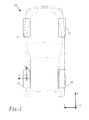
- Fig. 1 schematically illustrates a vehicle 10, such as a car, provided with a plurality of wheels 12, 14, 16, 18.
- the vehicle 10 extends in a global longitudinal direction X which is substantially parallel to the normal direction of travel of the vehicle 10.
- the vehicle 10 extends in a global vertical direction Z which is substantially normal to a road on which the vehicle 10 is located.
- the vehicle 10 extends in a global lateral direction Y which is substantially perpendicular to the global longitudinal direction X as well as the global vertical direction Z.
- Each one of the wheels 12, 14, 16, 18 extends in: a longitudinal direction x, a lateral direction y and a vertical direction z.
- the local direction x of each wheel is substantially parallel to the global longitudinal direction X of the vehicle 10.
- each one of the wheels 12, 14, 16, 18 is furnished with a tire (not shown in Fig. 1 ) providing a contact area between the wheel and a road on which the vehicle 10 is travelling.
- tire not shown in Fig. 1
- wheel-to-road contact parameters such as the friction coefficient ⁇ between the tire and the road, may vary and the present invention provides a method for estimating such contact parameters.
- the present invention provides a method for estimating the friction coefficient for a longitudinal case, e.g. when a wheel is subjected to loads extending substantially in its longitudinal direction x, as well as for a lateral case, wherein a wheel is subjected to loads which are substantially parallel to the lateral direction y.
- the methods for the two aforementioned cases may be generalized so as to yield cases with oblique loading, i.e. cases wherein a wheel is subjected to longitudinal as well as lateral loads.
- a longitudinal wheel load F x relates to a load extending substantially parallel to the longitudinal direction x
- a lateral wheel load F y relates to a load extending substantially parallel to the lateral direction y
- a vertical wheel load F z relates to a load extending substantially parallel to the vertical direction z.
- a moment M z around an axis extending parallel to the vertical direction z. This moment M z is also referred to as an aligning moment.
- a model of the tire - and in particular a model of the contact area between the tire and the road - is preferred.
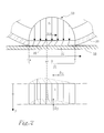
- Fig. 2 schematically illustrates one preferred tire model to be used in the method of the present invention, namely the so called brush model.
- the brush model is obtained by dividing the volume of a tire 20 in the contact region - or contact patch 22 - into small brush elements, or bristles, see Fig. 2 .
- Each bristle is assumed to deform independently in the longitudinal and lateral directions.
- Useful in the model is the separation of the contact patch 22 into one adhesive 24 and one sliding 26 region. In the adhesive region 24, the bristles adhere to a road surface 28 and the deformation force is carried by static friction. In the sliding region 26, the bristles slide across the road surface 28 under influence of sliding friction.
- ⁇ ( ⁇ i , C oi , ⁇ ) denotes the normalized tire force
- ⁇ x 0 3 ⁇ ⁇ / C 0 ⁇ x
- ⁇ y 0 3 ⁇ ⁇ / C 0 ⁇ y
- C 0 x , C 0y denotes the normalized tire stiffness and ⁇ is the friction coefficient.
- the rolling radius of a wheel is denoted R e and ⁇ is the rotational velocity of the wheel.
- the expression according to Eq. 2 is a preferred expression for the slip of the wheel which expression is useful when estimating the friction between the tire and the road. As such, the expression according to Eq. 2 is preferred when establishing methods for determining at least a first parameter - such as the friction - relating to a wheel-to-road contact.
- a first parameter determination method comprising the following steps:
- the fictive relation E may have to be adjusted to that specific load case.
- the fictive relation E may be adjusted so as to model a specific physical condition, e.g. an equilibrium in forces or moments in a specific direction.
- the parameters governing that specific condition may also have to be adjusted, resulting in that fictive relations E for different load cases may include different sets of input parameters. This will be explained more thoroughly hereinbelow for different load cases: a lateral case, a longitudinal case and a combinations thereof, starting with a lateral case.
- the caster offset of a wheel is defined as the distance on the road between where the vertical post, e.g. a strut of a wheel suspension, would touch the road and the point where the wheel touches the road. Furthermore, the parameter a in Eq. 3 stipulates half the tire effective length in the longitudinal direction x of the contact patch.
- the equation governing the aligning torque M z is dependent on the actual contact condition between the wheel and the road, wherein the condition denoted NS is indicative of that the contact is non-saturated and the condition denoted S is indicative of that the contact is saturated, i.e. that there is no adhesion in the contact patch.
- the relation as defined in Eq. 4 may constitute the fictive relation E as laid out in the description of the general parameter determination method of the present invention.
- the wheel parameters included in the fictive relation E - and which parameters thus need to be determined in the determination method of the present invention - are: the aligning moment M z , the lateral force F y , the vertical force F z and the caster offset of the wheel ⁇ c .
- the relation defined therein comprises two unknown parameters, the first one being the tire-to-road friction ⁇ and the other being the half the tire effective length a.
- the tire-to-road friction ⁇ may be regarded as the first parameter whereas half the tire effective length a may be regarded as the second parameter.
- the method of determining the first parameter - which in this case is the tire-to-road friction ⁇ - may for the lateral case be regarded as comprising a step of finding the parameter pair ( ⁇ ,a) fulfilling the fictive relation E as presented in Eq. 4.
- the set of second parameters in this case includes only one parameter, namely half the tire effective length a.
- the parameter a relating to half the tire effective length will be referred to as a second parameter.
- the present invention proposes a step of establishing a quality measure QM, which quality measure QM is indicative of how well the fictive relation E is fulfilled.
- the problem of finding the parameter pair ( ⁇ ,a) fulfilling the fictive relation E may now be reformulated as how to find an appropriate parameter pair ( ⁇ ,a) which results in a preferred value of the quality measure QM.
- QM M z + ⁇ sign F y ⁇ F z ⁇ a ⁇ 1 - 1 - F y F z ⁇ ⁇ 1 3 ⁇ 1 - F y F z ⁇ ⁇ + ⁇ c a ⁇ F y F z ⁇ ⁇ 2
- QM M z + ⁇ sign F y ⁇ F z ⁇ a ⁇ 1 - 1 - F y F z ⁇ ⁇ 1 3 ⁇ 1 - F y F z ⁇ ⁇ + ⁇ c a ⁇ F y F z ⁇ ⁇ .
- the problem of finding a parameter pair ( ⁇ ,a) resulting in a preferred value of the quality measure QM may be regarded as an optimization problem or, even more specifically, a minimization problem, viz min ⁇ , a QM .
- the fictive relation E as well as the quality measure QM may be regarded as relating to an instantaneous wheel load condition.
- the fictive relation E as well as the quality measure QM may be regarded as relating to an instantaneous wheel load condition.
- two or more measurement samples are generally desired in order to obtain a filtered (e.g. average) value of the parameter pair ( ⁇ ,a) during a certain time period. This reasoning as regards two or more measurement samples applies to all the embodiments of the present invention presented hereinbelow.
- the minimization problem as presented in Eq. 9 may be solved in a plurality of ways in order to obtain the preferred parameter pair ( ⁇ ,a).
- the determination method of the present invention proposes two preferred implementations of a method of solving the above minimization problem, which implementations are presented hereinbelow.
- each one of the two implementations is based on an insight made by the inventors of the present invention, namely that the fictive relation E in the lateral case, i.e. the relation E relating to the aligning moment M z as stipulated in Eq. 4, is not linearly proportional to the first parameter, i.e. the tire-to-road friction ⁇ .
- This implementation of the method of finding the appropriate values of the parameter pair ( ⁇ ,a) may be referred to as a grid-approach and is illustrated in Fig. 3 .
- the corresponding value of the quality measure QM may be determined and the combination of the first and second parameter ( ⁇ i ,a j ) resulting in the most preferred, which generally is the lowest, value of the quality measure is selected to constitute the preferred parameter pair ( ⁇ ,a).
- a further variant of the first implementation may comprise the steps of firstly selecting the sets of the first and second parameters ⁇ ,a and then determining the value of the quality measure QM for a plurality, preferably all, of the combinations of the sets of the first and second parameters wherein the order of combining the sets may be selected according to a predetermined scheme or may even be selected randomly.
- the second implementation utilizes the insight that the fictive relation E, c.f. Eq. 4, is in fact linearly proportional to the second parameter a.
- the aligning moment M z is an affine function of the second parameter a.
- a value of the second parameter a i as well as the corresponding local value of the quality measure QM i is determined. Then, the values of all the local quality measures QM i are compared to one another and the lowest local quality measure QM i is selected to be the preferred one. The corresponding values of the first and second parameters ⁇ ⁇ , a i are thus selected to constitute the preferred parameter pair ( ⁇ ,a).
- assumption a) hereinabove a person skilled in the art may realize that this assumption may be most preferred when studying two wheels 12, 18 which are located on the same side of a vehicle 10 since it is likely that these to wheels will experience approximately the same wheel-to-road contact. However, there may of course be situations, e.g. when the vehicle 10 is travelling on a substantially homogenous road, wherein assumption a) may be appropriate for any two wheels of a vehicle 10.
- a relation between the longitudinal velocity v x 1 of the first wheel 12 and the longitudinal velocity v x 2 of the second wheel 18 may be established.
- the above-mentioned relation is formulated such that the longitudinal velocity v x 1 of the first wheel 12 is assumed to equal the longitudinal velocity v x 2 of the second wheel 18, i.e. the stiffnesses of the members connecting the first and second wheels 12, 18 are assumed to be infinitely high.
- the constants K 1 and K 2 of Eq. 12 are in this case assumed to be zero.
- the left hand side LHS of the equation contains data which may be determined by direct or indirect measurements, namely data as regards the rolling radius R e and the rotational velocity ⁇ of each wheel 12, 18 and these data are also present in the right hand side RHS.
- the right hand side RHS of Eq. 15 contains data as regards the normalized longitudinal forces f x1 , f x2 of each wheel which forces may be estimated by a simple dynamic load transfer method which will be presented in detail hereinbelow.
- the relation according to Eq. 15 may be regarded as constituting the fictive relation E.
- Eq. 15 may be regarded as an alternative to Eq. 4 to constitute the fictive relation E.
- the parameters thus needed to be determined in the parameter determination method of the present invention are the rolling radius R e ; the rotational velocity ⁇ and normalized longitudinal force f x of each one of the first 12 and second 18 wheels, respectively.
- the equation presented in Eq. 16 may be referred to as a longitudinal force relation RF x .
- the distribution of the driving or braking is normalized, such that: ⁇ i ⁇ i ⁇ 1.
- the distribution ⁇ i may correspond to a normalized pressure of the braking system for each wheel of the vehicle.
- the unknown parameters of the fictive relation E namely the friction ⁇ and the tire stiffnesses C ox1 , C ox2 of the first and second wheel, respectively, may be estimated by a method similar to the one presented for the lateral case.
- a quality measure QM indicative of how well the fictive relation E according to Eq. 15 is fulfilled is firstly established. Examples of appropriate quality measures QM for Eq.
- the problem of finding a parameter set ( ⁇ ,C ox1 , C ox2 ) resulting in a preferred value of the quality measure QM may be regarded as an optimization problem or, even more specifically, a minimization problem, viz min ⁇ , C 0 ⁇ x ⁇ 1 , C 0 ⁇ x ⁇ 2 QM .
- Obtaining the values of the first and second tire stiffness C ox1 , C ox2 may be performed by utilizing traditional linear minimization techniques.
- the fictive relation E in the longitudinal case as stipulated in Eq. 15 is linearly proportional to the inverse of the tire stiffnesses C ox1 , C ox2 .
- the second implementation for determining an appropriate parameter set ( ⁇ ,C ox1 , C ox2 ) is basically the same as in the lateral case, be it that the minimization step for finding the local minimum QM i of the quality measure QM involves a two-dimensional minimization step, namely as regards the two parameters (1/C ox1 , 1/C ox2 ).
- the fictive relation E as defined therein is actually linearly proportional to the change ⁇ R e 1 in the rolling radius R e1 of the first wheel.
- the set of second parameters may in this case be constituted by the first and second tire stiffness C ox1 , C ox2 as well as the change ⁇ R e 1 in the rolling radius R e1 of the first wheel.
- the fictive relation E as stipulated by Eq. 15 may be expanded so as to include wheel load conditions for a plurality of time instants [t 0 ... t n ].
- the value of the first parameter relating to the tire-to-road contact - which first parameter preferably is the friction ⁇ - may be determined by a determination method which method is used in either a lateral case or a longitudinal case.
- the inventors of the present invention have also realized that either one of the aforesaid cases may be generalized to an oblique load case, i.e. a case wherein the wheel is subjected to lateral as well as longitudinal loads.
- the inventors of the present invention have realized that the relation presented in Eq. 3 may be generalized so as to also include a term relating to the load in the longitudinal direction.
- a load scenario may emanate from a driving situation wherein the vehicle 10 - onto which the wheel is mounted - is subjected to an acceleration or a retardation at the same time as the vehicle 10 is turning.
- M z - ⁇ a ⁇ f y f ⁇ ⁇ ⁇ 1 - f ⁇ + ⁇ c a ⁇ f ⁇ .
- ⁇ 1 - f ⁇ / 3 1
- f f x 2 + f y 2 .
- the relation as stipulated in Eq. 21 also includes a parameter relating to the longitudinal load f x an estimation of which has already been presented, c.f. Eq. 16.
- the relation modelling the aligning moment is an affine function of half the tire effective length a.
- appropriate values of the friction ⁇ as well as half the tire effective length a may be determined using any one of the determination methods, i.e. the first or second implementation, discussed hereinabove in conjunction with the lateral case.
- C in Eq. 22 is a parameter relating to the stiffness in the longitudinal C 0x as well as the lateral C 0y direction of the tire.
- one preferred approximation which may be introduced when formulating the relation as laid out in Eq. 22 is that the longitudinal tire stiffness equals the lateral tire stiffness.
- the determination method as previously proposed as regards the longitudinal case, c.f. Eq 10 to Eq. 20, may be modified by replacing the Eq. 2 relation for the longitudinal slip ⁇ x with the expression as stipulated in Eq. 22. Without going into details, this will result in a fictive relation E wherein the friction ⁇ and the combined stiffnesses of a first and a second wheel C 1 , C 2 are unknown parameters. Furthermore, the aforesaid fictive relation will be linearly proportional to an inverse of each one of the first and second combined tire stiffnesses C 1 , C 2 . As such, at least the first parameter - i.e.
- the friction ⁇ - may in this case be determined by a parameter determination method similar to any one of the methods discussed hereinabove with reference to the longitudinal case.
- an implementation of the method presented hereinabove may use the assumption that the combined tire stiffness C 1 of the first wheel equals the combined stiffness C 2 of the second wheel.
- the present invention provides for a method of determining at least a first parameter ⁇ relating to a wheel-to-road contact for a plurality of load cases for one or several wheels.
- the step of determining an appropriate value of the second parameter for a selected value of the first parameter may include other optimization techniques than the ones presented hereinabove.
- such optimization techniques may comprise a Fibonacci search algorithm or a Newton-Rapson search algorithm.
- a preferred determination method may comprise a step of firstly determining the actual wheel load condition, e.g. if the wheel load is longitudinal, lateral or a combination thereof, and then selecting a specific first parameter implementation, which implementation may preferably be selected from any one of the four embodiments presented hereinabove.
Landscapes
- Engineering & Computer Science (AREA)
- Transportation (AREA)
- Mechanical Engineering (AREA)
- Physics & Mathematics (AREA)
- Automation & Control Theory (AREA)
- Mathematical Physics (AREA)
- Control Of Driving Devices And Active Controlling Of Vehicle (AREA)
Abstract
Furthermore, the present invention relates to a computer program product adapted to carry out the method of the present invention; an electronic control unit comprising such a computer program product, and a vehicle (10) comprising such an electronic control unit.
Description
- The present invention relates to a method for determining at least a first parameter relating to a wheel-to-road contact wherein the wheel has a longitudinal and a lateral extension. The method comprises a step of determining a plurality of wheel parameters relating to the load on the wheel and/or relating to the motion of the wheel.
- Furthermore, the present invention relates to a computer program product adapted to carry out the method of the present invention; an electronic control unit comprising such a computer program product, and a vehicle comprising such an electronic control unit.
- For a vehicle furnished with a plurality of wheels, the values of parameters relating to the wheel-to-road contact for at least one of the wheels is often of great interest for the driver and/or a driver assistance system of the vehicle. Such a system may for instance be: an anti-skid system (ABS); a traction control system (ASR), or an electronic stability program (ESP).
- One parameter relating to the wheel-to-road contact, which parameter is often an important parameter for any one of the systems hereinabove, is the so called slip. In a longitudinal wheel load case, i.e. when a wheel is subjected to loads generally extending in a direction perpendicular to the axis of the rotation of the wheel, the slip is defined in terms of the difference of the longitudinal velocity and the rotational speed of the wheel normalized by the rotational speed of the wheel. In a lateral wheel load case, i.e. when a wheel is subjected to loads extending in a direction parallel to the axis of rotation, the slip is generally defined in terms of a ratio between the wheel's lateral velocity and the aforesaid rotational speed.
- Another parameter which generally is of interest is the wheel-to-road friction. For instance, a value of the wheel-to-road friction may be communicated to the driver of the vehicle so that he or she can adjust his or her driving according to the present wheel-to-road friction. Moreover, the wheel-to-road friction may be used, preferably together with the slip as defined hereinabove, in any one of the previously mentioned driver assistance systems.
- As such, it is desirable to obtain data as regards the friction and/or the slip whilst driving. However, the friction is generally difficult to measure or sense directly during driving; hence it needs to be determined by using e.g. indirect friction determination methods.
- To this end, the prior art for instance proposes the use of recursive estimation algorithms which are primarily based on the assumption that tire forces may be expressed by a nonlinear function which is dependent on the slip as well as a plurality of parameters which describe the actual condition of the tire and the road surface.
- For example,
US 5 513 907 proposes that a method be used, in which method the wheel speed, the rotational acceleration of the vehicle wheel and a braking pressure is determined. The wheel slip is then calculated from the parameters above and the friction is determined by means of linear recursive estimation algorithms. - However, the method as proposed in '907 generally requires that the friction be approximated by an equation which includes the wheel slip, which approximation may in itself impair the result of the estimated friction. Furthermore, the linear recursive method used in '907 may be time consuming to execute and may thus require a long computing time and/or advanced computer processing units.
- As such, and as may be realized from the above, there is a need for an improved method for determining at least a first parameter relating to a wheel-to-road contact, which parameter preferably is the friction, wherein the method requires less time to be executed and/or provides a more accurate result as regards the determined value of the first parameter.
- A first object of the present invention is to provide a first parameter determination method, which method provides a measure of the first parameter in an appropriately short time and/or by requiring an appropriately low capacity as regards a computer processing unit.
- A second object of the present invention is to provide a first parameter determination method, which method utilizes a robust method for obtaining the first parameter.
- A third object of the present invention is to provide a first parameter determination method, which method may be used for several wheel loads cases, e.g. longitudinal and/or lateral wheel load cases.
- A fourth object of the present invention is to provide a first parameter determination method, which method does not require the introduction of a simplified approximation of the first parameter in terms of other parameters relating to the wheel and/or wheel-to-road contact.
- At least one of the aforementioned objects is achieved by a method for determining at least a first parameter relating to a wheel-to-road contact as set out in appended claim 1.
- Thus, the invention relates to a method for determining at least a first parameter relating to a wheel-to-road contact, wherein the wheel has a longitudinal and a lateral extension and wherein the method comprises a step of determining a plurality of wheel parameters relating to the load on the wheel and/or relating to the motion of the wheel.
- According to the present invention, the method further comprises the steps of:
- establishing a fictive relation comprising: at least one of the plurality of wheel parameters, the first parameter and a set of second parameters relating to the wheel-to-road contact, wherein the relation, at least during a longitudinal wheel load case or a lateral wheel load case, is linearly proportional to each one of the parameters in the set of second parameters or an inversion thereof;
- establishing a quality measure indicative of how well the fictive relation is fulfilled;
- selecting a set of individual values of the first parameter;
- for at least two of the individual values in the set:
- ○ determining the value each one of the parameters in the set of second parameters which results in a preferred quality measure for the individual value of the first parameter;
- selecting the value of the first parameter as the individual value from the at least two individual values which corresponding preferred quality measure is indicative of that the fictive relation is best fulfilled.
- Thus, by utilizing the aforementioned method of the invention, an appropriate value of the first parameter may be determined by a robust method which will always provide a result as regards the first parameter. Furthermore, since the method of the invention proposes that the fictive relation is proportional to each one of a set of second parameters relating to the wheel-to-road contact, this means that the method may be rapidly executed, since finding appropriate values of each one of the set of second parameters as regards the fictive relation may be performed by for instance using well-known and rapid linear optimization techniques.
- Moreover, the method of the present invention may preferably be used in a lateral wheel load case, a longitudinal wheel load case or a combination thereof. As such, the method of the present invention provides for that basically only one type of parameter determination method needs to be implemented in e.g. a electronic control unit of a vehicle.
- As used herein the expression "road" relates to any type of base on which the wheels of a vehicle may be supported whilst driving. Consequently, the expression "road" as used in the present application is not limited to roads made by man.
- In a preferred embodiment of the present invention, the quality measure is an error function for the fictive relation such that a value of zero of the quality measure is indicative of that the fictive relation is fulfilled.
- By arranging the quality measure as an error function, a step of finding parameters providing an appropriate value of the quality measure may be regarded as an optimization step. As such, well-known and tested optimization techniques may be used in the method of the present invention, which ensures that the parameter determination method may be easily and efficiently implemented.
- In another embodiment of the present invention, the step of determining the value of each one of the parameters in the set of second parameters comprises a step of minimizing the quality measure.
- In a further embodiment of the present invention, the step of minimizing the quality measure is performed by utilizing a linear optimization technique.
- As previously mentioned, linear optimization techniques are well-known from the prior art for being rapid and robust.
- In another embodiment of the present invention, the step of determining the value of each one of the parameters in the set of second parameters comprises the steps of:
- selecting a second set of individual values of the second parameter;
- for at least two of the individual values in the second set:
- ○ selecting the value of the second parameter as the individual value which results in the preferred quality measure.
- In a further embodiment of the present invention, the first parameter relates to a wheel-to-road friction.
- In another embodiment of the present invention, the method is performed for a wheel load case comprising a lateral load, wherein the wheel parameters comprise a subset which in turn comprises: an aligning torque, a vertical force and the lateral force of the wheel,
wherein the fictive relation comprises the subset. - In a further embodiment of the present invention, the fictive relation further comprises the following parameters: the wheel-to-road friction, a length parameter relating to an effective length of a contact patch between the wheel and the road and a caster offset of the wheel,
wherein the length parameter is comprised in the set of second parameters. - In another embodiment of the present invention, the wheel is mounted on a vehicle and the lateral force is determined by a lateral force relation comprising the following parameters: a vehicle mass, a vehicle longitudinal acceleration, a vehicle lateral acceleration and a vehicle yaw acceleration.
- In a further embodiment of the present invention, the load case also comprises a longitudinal load and the fictive relation further comprises a wheel parameter representing the longitudinal load.
- In another embodiment of the present invention, the method is performed for a vehicle comprising a first and a second wheel during a load case comprising a longitudinal load,
wherein the first wheel has a first longitudinal velocity and the second wheel has a second longitudinal velocity. The method comprises a step of establishing a relation between the first and second longitudinal velocities, wherein the fictive relation comprises the following parameters: a longitudinal load of the first wheel and a longitudinal load of the second wheel. - In a further embodiment of the present invention, the fictive relation further comprises the following parameters: a first longitudinal tire stiffness of the first wheel, a second longitudinal tire stiffness of the second wheel and the wheel-to-road friction, which wheel-to-road friction is assumed to be equal for the first and second wheels, wherein the first and second longitudinal tire stiffnesses are comprised in the set of second parameters.
- In another embodiment of the present invention, the load case also comprises a lateral load and the fictive relation further comprises: a wheel parameter representing the longitudinal load, a first combined tire stiffness of the first wheel and a second combined tire stiffness of the second wheel, wherein the first and second combined tire stiffnesses are comprised in the set of second parameters.
- In a further embodiment of the present invention, the fictive relation further comprises the following parameters: an effective rolling radius of the first wheel, an effective rolling radius of the second wheel, a rotational velocity of the first wheel and a rotational velocity of the second wheel.
- In another embodiment of the present invention, the wheel is mounted on a vehicle and the lateral force is determined by a longitudinal force relation comprising the following parameters: a vehicle mass, a vehicle longitudinal acceleration and a parameter representative of a driving or breaking force between the wheels of the vehicle.
- As second aspect of the present invention relates to a computer program product comprising a computer program containing computer program code executable in a computer or a processor to implement all the steps of a first parameter determination method of the present invention. The product is stored on a computer-readable medium or a carrier wave.
- A third aspect of the present invention relates to an electronic control unit comprising a computer program product according to the second aspect of the present invention and which electronic control unit is arranged to execute a first parameter determination method according to the first aspect of the present invention.
- A fourth aspect of the present invention relates to a vehicle comprising an electronic control unit according to the third aspect of the present invention.
- The present invention will hereinafter be further explained by means of non-limiting examples with reference to the appended figures wherein;
- Fig. 1
- is schematic plan view of a vehicle furnished with four wheels;
- Fig. 2
- is schematic cross section side view of a tire contacting a road;
- Fig. 3
- is a graph illustrating a minimization procedure according to a preferred implementation of a parameter determination step of the present invention, and
- Fig. 4
- is a graph illustrating a minimization procedure according to another preferred implementation of a parameter determination step of the present invention.
- The invention will, in the following, be exemplified by embodiments. It should however be realized that the embodiments are included in order to explain principles of the invention and not to limit the scope of the invention, defined by the appended claims.
-
Fig. 1 schematically illustrates avehicle 10, such as a car, provided with a plurality ofwheels Fig. 1 , thevehicle 10 extends in a global longitudinal direction X which is substantially parallel to the normal direction of travel of thevehicle 10. Furthermore, thevehicle 10 extends in a global vertical direction Z which is substantially normal to a road on which thevehicle 10 is located. Moreover, thevehicle 10 extends in a global lateral direction Y which is substantially perpendicular to the global longitudinal direction X as well as the global vertical direction Z. - Each one of the
wheels vehicle 10 is driving straight ahead, the local direction x of each wheel is substantially parallel to the global longitudinal direction X of thevehicle 10. Furthermore, each one of thewheels Fig. 1 ) providing a contact area between the wheel and a road on which thevehicle 10 is travelling. As may be appreciated by a person skilled in the art, depending on inter alia the characteristics of the tire as well as the road, wheel-to-road contact parameters, such as the friction coefficient µ between the tire and the road, may vary and the present invention provides a method for estimating such contact parameters. It should be noted that although the embodiments hereinbelow relate to methods of determining the aforesaid friction coefficient µ, the method of the present invention may also be appropriate to use when determining other parameters relating to the wheel-to-road contact, such as the slip σ. - In particular, the present invention provides a method for estimating the friction coefficient for a longitudinal case, e.g. when a wheel is subjected to loads extending substantially in its longitudinal direction x, as well as for a lateral case, wherein a wheel is subjected to loads which are substantially parallel to the lateral direction y. However, as may be realized from the description hereinbelow, the methods for the two aforementioned cases may be generalized so as to yield cases with oblique loading, i.e. cases wherein a wheel is subjected to longitudinal as well as lateral loads.
- It should be noted that in the description hereinbelow, references are often made to wheel loads and moments in various directions. As such: a longitudinal wheel load Fx relates to a load extending substantially parallel to the longitudinal direction x; a lateral wheel load Fy relates to a load extending substantially parallel to the lateral direction y, and a vertical wheel load Fz relates to a load extending substantially parallel to the vertical direction z. Moreover, reference is made to a moment Mz around an axis extending parallel to the vertical direction z. This moment Mz is also referred to as an aligning moment.
- In order to estimate the aforesaid friction coefficient between a tire and the road, a model of the tire - and in particular a model of the contact area between the tire and the road - is preferred.
Fig. 2 schematically illustrates one preferred tire model to be used in the method of the present invention, namely the so called brush model. The brush model is obtained by dividing the volume of atire 20 in the contact region - or contact patch 22 - into small brush elements, or bristles, seeFig. 2 . Each bristle is assumed to deform independently in the longitudinal and lateral directions. Useful in the model is the separation of thecontact patch 22 into one adhesive 24 and one sliding 26 region. In theadhesive region 24, the bristles adhere to aroad surface 28 and the deformation force is carried by static friction. In the slidingregion 26, the bristles slide across theroad surface 28 under influence of sliding friction. - Assuming a parabolic pressure distribution between the
tire 20 and the road 28 -which load distribution is denoted by 30 inFig. 2 - a mathematical formulation of a normalized longitudinal or lateral tire force fi = Fi / Fz (wherein i=x or i=y) becomes
wherein: Ψ(σ i ,Coi , µ) denotes the normalized tire force;
- Eq. 1 hereinabove may be rearranged such that the slip σi may be expressed in terms of the other parameters, namely

- The expression according to Eq. 2 is a preferred expression for the slip of the wheel which expression is useful when estimating the friction between the tire and the road. As such, the expression according to Eq. 2 is preferred when establishing methods for determining at least a first parameter - such as the friction - relating to a wheel-to-road contact. Thus, what the present invention proposes is a first parameter determination method comprising the following steps:
- determining a plurality of wheel parameters relating to the load on the wheel and/or relating to the motion of the wheel,
- establishing a fictive relation E comprising: at least one of the plurality of wheel parameters, the first parameter and a set of second parameters relating to the wheel-to-road contact, wherein the relation, at least during a longitudinal wheel load case or a lateral wheel load case, is linearly proportional to each one of the parameters in the set of second parameters or an inversion thereof;
- establishing a quality measure QM indicative of how well the fictive relation E is fulfilled;
- selecting a set of individual values of the first parameter;
- for at least two of the individual values in the set:
- ○ determining the value for each one of the parameters in the set of second parameters which results in a preferred quality measure for the individual value of the first parameter;
- selecting the value of the first parameter as the individual value from the at least two individual values which corresponding preferred quality measure is indicative of that the fictive relation E is best fulfilled.
- As may be realized by a person skilled in the art, depending on the load case studied when determining the first parameter, i.e. whether a longitudinal case; a lateral case or a combination thereof is studied, the fictive relation E may have to be adjusted to that specific load case. As such, depending on the actual load case, the fictive relation E may be adjusted so as to model a specific physical condition, e.g. an equilibrium in forces or moments in a specific direction. Naturally, depending on the actual physical condition modelled by the fictive relation E, the parameters governing that specific condition may also have to be adjusted, resulting in that fictive relations E for different load cases may include different sets of input parameters. This will be explained more thoroughly hereinbelow for different load cases: a lateral case, a longitudinal case and a combinations thereof, starting with a lateral case.
- In a pure lateral load case, i.e. when the wheel is subjected to a pure lateral tire force, i.e. a force being substantially parallel to the lateral direction y of the wheel, the aligning torque Mz of the wheel may be formulated according to the following:

wherein:
- As may be gleaned from Eq. 3, the equation governing the aligning torque Mz is dependent on the actual contact condition between the wheel and the road, wherein the condition denoted NS is indicative of that the contact is non-saturated and the condition denoted S is indicative of that the contact is saturated, i.e. that there is no adhesion in the contact patch.
- Now, assuming that the longitudinal force Fx as well as the slip σx are zero and combining Eq. 2 and Eq. 3, the following expression may be obtained:

- The relation as defined in Eq. 4 may constitute the fictive relation E as laid out in the description of the general parameter determination method of the present invention. As such, from Eq. 4 it is realized that the wheel parameters included in the fictive relation E - and which parameters thus need to be determined in the determination method of the present invention - are: the aligning moment Mz, the lateral force Fy, the vertical force Fz and the caster offset of the wheel δ c . As may further be realized from Eq. 4, the relation defined therein comprises two unknown parameters, the first one being the tire-to-road friction µ and the other being the half the tire effective length a. As such, again referring to the parameter determination method of the present invention, the tire-to-road friction µ may be regarded as the first parameter whereas half the tire effective length a may be regarded as the second parameter.
- As may be gleaned from Eq. 4, the fictive relation E in the later case comprises the expression


- This normalized lateral force fy may be estimated by a simple load dynamic load transfer model - or a lateral force relation RFy - and a computation of the lateral force acting on the wheels of the vehicle from the vehicle longitudinal and lateral accelerations ax, ay as well as the vehicle yaw acceleration ψ̈ such that:

- Thus, the method of determining the first parameter - which in this case is the tire-to-road friction µ - may for the lateral case be regarded as comprising a step of finding the parameter pair (µ,a) fulfilling the fictive relation E as presented in Eq. 4. As such, with reference to the determination method of the present invention as previously been presented, the set of second parameters in this case includes only one parameter, namely half the tire effective length a. Thus, in the presentation of the determination method for a lateral wheel load case presented hereinbelow, the parameter a relating to half the tire effective length will be referred to as a second parameter.
- In order to obtain the aforesaid parameter pair (µ,a) fulfilling the fictive relation E, the present invention proposes a step of establishing a quality measure QM, which quality measure QM is indicative of how well the fictive relation E is fulfilled. The problem of finding the parameter pair (µ,a) fulfilling the fictive relation E may now be reformulated as how to find an appropriate parameter pair (µ,a) which results in a preferred value of the quality measure QM.
- Examples of such quality measures QM may for instance be:


- As may be realized by a person skilled in the art, if a quality measure QM is formulated according to either one of Eq. 7 or Eq. 8 hereinabove, the problem of finding a parameter pair (µ,a) resulting in a preferred value of the quality measure QM may be regarded as an optimization problem or, even more specifically, a minimization problem, viz

- As may be gleaned when studying Eq. 4 to Eq. 9 hereinabove, the fictive relation E as well as the quality measure QM may be regarded as relating to an instantaneous wheel load condition. However, although it may be possible to determine an instantaneous value of each one of the parameters in the pair (µ,a), in practice, two or more measurement samples are generally desired in order to obtain a filtered (e.g. average) value of the parameter pair (µ,a) during a certain time period. This reasoning as regards two or more measurement samples applies to all the embodiments of the present invention presented hereinbelow.
- The minimization problem as presented in Eq. 9 may be solved in a plurality of ways in order to obtain the preferred parameter pair (µ,a). However, the determination method of the present invention proposes two preferred implementations of a method of solving the above minimization problem, which implementations are presented hereinbelow.
- Each one of the two implementations is based on an insight made by the inventors of the present invention, namely that the fictive relation E in the lateral case, i.e. the relation E relating to the aligning moment Mz as stipulated in Eq. 4, is not linearly proportional to the first parameter, i.e. the tire-to-road friction µ. As such, in order to overcome the nonlinearity problem as regards the first parameter µ, each one of the implementations comprises a step of selecting a set of individual values {µ i } i=1,n of the first parameter µ. Furthermore, each one of the first and second implementations comprises a step of, for each one of the individual values {µ i } i=1,n of the first parameter µ, identifying the corresponding value of the second parameter a which results in a minimum, or at least a value below a preferred threshold, of the quality measure QM.
- To this end, the first implementation proposes a step of selecting a second set of individual values


Fig. 3 . - As such, for each one of the nodes in the grid generated by the individual values of the first and second parameter, respectively, the corresponding value of the quality measure QM may be determined and the combination of the first and second parameter (µi,aj) resulting in the most preferred, which generally is the lowest, value of the quality measure is selected to constitute the preferred parameter pair (µ,a). It should be noted that although the first implementation of determining the preferred parameter pair (µ,a) is described hereinabove in terms of firstly selecting a set of individual values {µ i } i=1,n of the first parameter µ and secondly selecting a second set of individual values

- The second implementation utilizes the insight that the fictive relation E, c.f. Eq. 4, is in fact linearly proportional to the second parameter a. In other words, in Eq. 4, the aligning moment Mz is an affine function of the second parameter a. This means that, for a given value of the first parameter µ¡, finding a value of the second parameter which results in a local minimum for the quality measure QM may be performed by utilizing traditional linear minimization techniques. As such, for each one of the set of individual values {µ i } i=1,n of the first parameter µ, a corresponding value of the first parameter a is determined which locally minimizes the quality measure QM. Thus, for each one of the set of individual values {µ i } i=1,n of the first parameter µ, a value of the second parameter ai , as well as the corresponding local value of the quality measure QMi is determined. Then, the values of all the local quality measures QMi are compared to one another and the lowest local quality measure QMi is selected to be the preferred one. The corresponding values of the first and second parameters µ¡, ai are thus selected to constitute the preferred parameter pair (µ,a). The second implementation is illustrated in
fig. 4 , wherein corresponding value of the second parameter a is indicated for each one of the set of individual values {µ i } i=1,n of the first parameter µ. - An embodiment of the determination method of the present invention, which embodiment is useful when studying a pure longitudinal case, i.e. a case with pure longitudinal acceleration or retardation, will be presented hereinbelow. In contrast to the lateral case,
wherein the aligning torque of a wheel is used for deriving a quality measure which is to be minimized, the longitudinal case uses the longitudinal slip as a starting point, which longitudinal slip is defines as:
- Now, combining Eq. 2 and Eq. 10, the following relation for the longitudinal velocity vx of a wheel may be formulated:

- Now, the present embodiment of the invention utilizes the following two assumptions:
- a) for at least two
wheels vehicle 10, the friction µ between the tires and the road is the same, and - b) a relationship between the longitudinal velocities Vx1, Vx2 of the first and a
second wheel - As for assumption a) hereinabove, a person skilled in the art may realize that this assumption may be most preferred when studying two
wheels vehicle 10 since it is likely that these to wheels will experience approximately the same wheel-to-road contact. However, there may of course be situations, e.g. when thevehicle 10 is travelling on a substantially homogenous road, wherein assumption a) may be appropriate for any two wheels of avehicle 10. - As regards assumption b), depending on inter alia the stiffnesses in the wheel suspension of the two
wheels vehicle 10, a relation between the longitudinal velocity v x1 of thefirst wheel 12 and the longitudinal velocity v x2 of thesecond wheel 18 may be established. An example of such a relation may be:
second wheels first wheel 12 is assumed to equal the longitudinal velocity v x2 of thesecond wheel 18, i.e. the stiffnesses of the members connecting the first andsecond wheels - Using this latter simplified assumption in combination with the teachings of Eq. 11, the following relation may be generated:

- By introducing the following general function:

- Eq. 13 may be reformulated to:

- As may be gleaned from Eq. 15, the left hand side LHS of the equation contains data which may be determined by direct or indirect measurements, namely data as regards the rolling radius Re and the rotational velocity ω of each
wheel - The parameters (Cox1, Cox2, µ) are unknown in Eq. 15. However, it should be realized that when the correct values of (Cox1, Cox2, µ) have been determined, Eq. 15 is fulfilled such that RHS=LHS. As such, with reference to the parameter determination method of the present invention, the relation according to Eq. 15 may be regarded as constituting the fictive relation E. Thus, in this respect, Eq. 15 may be regarded as an alternative to Eq. 4 to constitute the fictive relation E. Accordingly, the parameters thus needed to be determined in the parameter determination method of the present invention are the rolling radius Re; the rotational velocity ω and normalized longitudinal force fx of each one of the first 12 and second 18 wheels, respectively.
- As regards the normalized longitudinal forces, it should be noted that the normalized longitudinal force fx of one wheel may be estimated by the expression:

wherein α and β are vehicle constants describing a centre of gravity of thevehicle 10 and γi is a distribution of the driving or braking force between a front and rear axle of thevehicle 10. The equation presented in Eq. 16 may be referred to as a longitudinal force relation RFx. The distribution of the driving or braking is normalized, such that:
- For instance, the distribution γi may correspond to a normalized pressure of the braking system for each wheel of the vehicle.
- Now, returning to the fictive relation E as stipulated in Eq. 15 for the longitudinal case, the unknown parameters of the fictive relation E, namely the friction µ and the tire stiffnesses Cox1, Cox2 of the first and second wheel, respectively, may be estimated by a method similar to the one presented for the lateral case. As such, a quality measure QM indicative of how well the fictive relation E according to Eq. 15 is fulfilled is firstly established. Examples of appropriate quality measures QM for Eq. 15 are presented hereinbelow:


- In analogy with the embodiment of the method of the present invention relating to the lateral case, if a quality measure QM is formulated according to either one of Eq. 18 or Eq. 19 hereinabove, the problem of finding a parameter set (µ,Cox1, Cox2) resulting in a preferred value of the quality measure QM may be regarded as an optimization problem or, even more specifically, a minimization problem, viz

- Again, as for the lateral case, the minimization problem formulated in Eq. 20 may be solved by either one of the two implementations as presented in conjunction with the lateral case, namely a grid approach - which grid approach in the longitudinal case results in that a three-dimensional grid be generated - or an approach comprising a step of firstly selecting a set of individual values {µ i } i=1,n of the first parameter and for at least two of the individual values in the aforesaid set obtaining a value for each one of the tire stiffnesses Cox1, Cox2 which result in a local minimum for the quality measure QM. Obtaining the values of the first and second tire stiffness Cox1, Cox2 may be performed by utilizing traditional linear minimization techniques. To this end, it should be noted that the fictive relation E in the longitudinal case as stipulated in Eq. 15 is linearly proportional to the inverse of the tire stiffnesses Cox1, Cox2. Thus, as compared to the lateral case, the second implementation for determining an appropriate parameter set (µ,Cox1, Cox2) is basically the same as in the lateral case, be it that the minimization step for finding the local minimum QMi of the quality measure QM involves a two-dimensional minimization step, namely as regards the two parameters (1/Cox1, 1/Cox2).
- However, linear optimization techniques are basically identical when comparing a one-dimensional and a two-dimensional minimization problem, hence the steps of a method for finding the values of the parameters Cox1, Cox2 for an individual value µi are not further elaborated here.
- It should however be noted that one implementation of the embodiment described hereinabove may also use the assumption that the tire stiffness Cox1 of the first wheel equals the tire stiffness Cox2 of the second wheel such that the set of second parameters only includes one parameter Cox= Cox1= Cox2.
- With reference to Eq. 15, it should be noted that the relation defined therein in may be elaborated further in order to capture possible changes in the rolling radius Re of at least one of the first and second wheels whilst driving. In the explanation hereinbelow as regards how such changes may be accounted for, the rolling radius Re1 of the first wheel is used as an example. However, it should be noted that the approach described below is equally applicable for the rolling radius Re2 of the second wheel. Moreover, implementations of the approach may be used for rolling radii Re1, Re2 of both the first and second wheels.
- When including a possible change in rolling radius Re1 of the first wheel in the fictive relation E as defined in Eq. 15, the rolling radius Re1 of the first wheel may be formulated as:


- Moreover, in analogy with the lateral wheel load case, the fictive relation E as stipulated by Eq. 15 may be expanded so as to include wheel load conditions for a plurality of time instants [t0 ... tn].
- As may be realized from the description hereinabove, the value of the first parameter relating to the tire-to-road contact - which first parameter preferably is the friction µ - may be determined by a determination method which method is used in either a lateral case or a longitudinal case. However, the inventors of the present invention have also realized that either one of the aforesaid cases may be generalized to an oblique load case, i.e. a case wherein the wheel is subjected to lateral as well as longitudinal loads.
- As regards the determination method based on the lateral case as described hereinabove with reference to Eq. 3 to Eq. 9, the inventors of the present invention have realized that the relation presented in Eq. 3 may be generalized so as to also include a term relating to the load in the longitudinal direction. As an example, such a load scenario may emanate from a driving situation wherein the vehicle 10 - onto which the wheel is mounted - is subjected to an acceleration or a retardation at the same time as the
vehicle 10 is turning. Without going into details, the relation relating to the aligning moment Mz may be formulated as follows for the load case presented above:

- As may be appreciated by a person skilled in the art, compared to the aligning moment in the lateral case as modelled in Eq. 4, the relation as stipulated in Eq. 21 also includes a parameter relating to the longitudinal load fx an estimation of which has already been presented, c.f. Eq. 16. Furthermore, as may be gleaned from Eq. 21, the relation modelling the aligning moment is an affine function of half the tire effective length a. As such, appropriate values of the friction µ as well as half the tire effective length a may be determined using any one of the determination methods, i.e. the first or second implementation, discussed hereinabove in conjunction with the lateral case.
- As regards a determination method based on the longitudinal case as previously discussed, the inventors of the present invention have realized that the longitudinal slip of a wheel, c.f. Eq. 2, may be reformulated so as to also include a term relating to the lateral force fy acting on the wheel, such that:

- Utilizing the relation as disclosed in Eq. 22, the determination method as previously proposed as regards the longitudinal case, c.f. Eq 10 to Eq. 20, may be modified by replacing the Eq. 2 relation for the longitudinal slip σx with the expression as stipulated in Eq. 22. Without going into details, this will result in a fictive relation E wherein the friction µ and the combined stiffnesses of a first and a second wheel C1, C2 are unknown parameters. Furthermore, the aforesaid fictive relation will be linearly proportional to an inverse of each one of the first and second combined tire stiffnesses C1, C2. As such, at least the first parameter - i.e. the friction µ - may in this case be determined by a parameter determination method similar to any one of the methods discussed hereinabove with reference to the longitudinal case. As been previously discussed in relation with the longitudinal case, an implementation of the method presented hereinabove may use the assumption that the combined tire stiffness C1 of the first wheel equals the combined stiffness C2 of the second wheel.
- As may be realized from the description of the preferred embodiments hereinabove, the present invention provides for a method of determining at least a first parameter µ relating to a wheel-to-road contact for a plurality of load cases for one or several wheels. Further modifications of the invention within the scope of the appended claims are feasible. For example, the step of determining an appropriate value of the second parameter for a selected value of the first parameter may include other optimization techniques than the ones presented hereinabove. Purely by way of example, such optimization techniques may comprise a Fibonacci search algorithm or a Newton-Rapson search algorithm.
- Furthermore, a preferred determination method according to the present invention may comprise a step of firstly determining the actual wheel load condition, e.g. if the wheel load is longitudinal, lateral or a combination thereof, and then selecting a specific first parameter implementation, which implementation may preferably be selected from any one of the four embodiments presented hereinabove. As such, it will be realized that the present invention is not limited to the embodiments described above and illustrated in the drawings; rather a person skilled in the art will recognise many alterations and modifications that can be performed within the frame of the scope of protection of the appended claims.
Claims (19)
- A method for determining at least a first parameter (µ) relating to a wheel-to-road contact, wherein said wheel has a longitudinal (x) and a lateral (y) extension and wherein said method comprises a step of:- determining a plurality of wheel parameters relating to the load on the wheel and/or relating to the motion of the wheel,characterized in that:said method further comprises the steps of:- establishing a fictive relation (E) comprising: at least one of said plurality of wheel parameters, said first parameter (µ) and a set of second parameters (a, Cox1, Cox2) relating to said wheel-to-road contact, wherein said relation (E), at least during a longitudinal wheel load case or a lateral wheel load case, is linearly proportional to each one of said parameters (a, Cox1, Cox2) in said set of second parameters or an inversion thereof;- establishing a quality measure (QM) indicative of how well said fictive relation (E) is fulfilled;- selecting a set of individual values {µ i } i=1,n of said first parameter (µ);- for at least two of said individual values in said set:o determining the value for each one of said parameters (ai, Ci ox1, Ci ox2) in said set of second parameters which results in a preferred quality measure (QMi) for said individual value (µi) of said first parameter (µ);- selecting the value of said first parameter (µ) as the individual value (µi) from said at least two individual values which corresponding preferred quality measure (QMi) is indicative of that said fictive relation (E) is best fulfilled.
- The method according to claim 1, wherein said quality measure (QM) is an error function for said fictive relation (E) such that a value of zero of said quality measure (QM) is indicative of that said fictive relation (E) is fulfilled.
- The method according to claim 2, wherein said step of determining the value of each one of said parameters (ai, Ci ox1, Ci ox2) in said set of second parameters comprises a step of minimizing said quality measure (QM).
- The method according to claim 3, wherein said step of minimizing said quality measure (QM) is performed by utilizing a linear optimization technique.
- The method according to any one of claims 1 - 3, wherein said step of determining said value of each one of said parameters (ai, Ci ox1, Ci ox2) in said set of second parameters comprises the steps of:- selecting a second set of individual values for each one of said parameters (ai, Ci ox1, Ci ox2) in said set of second parameters
 - for at least two of said individual values in said second set:o selecting the value of each one of said parameters in said set of second parameters (ai, Ci ox1, Ci ox2) as the individual value
- The method according to any one of the preceding claims, wherein said first parameter (µ) relates to a wheel-to-road friction.
- The method according to claim 6, wherein said method is performed for a wheel load case comprising a lateral load (Fy), wherein said wheel parameters comprise a subset which in turn comprises: an aligning torque (Mz), a vertical force (Fz) and said lateral force (Fy) of said wheel, wherein said fictive relation (E) comprises said subset.
- The method according to claim 7, wherein said fictive relation (E) further comprises the following parameters: said wheel-to-road friction (µ) a length parameter (a) relating to an effective length of a contact patch between said wheel and said road and a caster offset (δc) of said wheel, wherein said length parameter (a) is comprised in said set of second parameters.
- The method according to claim 7 or 8, wherein said wheel is mounted on a vehicle (10) and said lateral force (Fy) is determined by a lateral force relation (RFy) comprising the following parameters: a vehicle mass (m), a vehicle longitudinal acceleration (ax), a vehicle lateral acceleration (ay) and a vehicle yaw acceleration (ψ̈).
- The method according to any one of claims 7 to 9, wherein said load case also comprises a longitudinal load (Fx) and said fictive relation (E) further comprises a wheel parameter representing said longitudinal load (Fx).
- The method according to claim 6, wherein said method is performed for a vehicle (10) comprising a first and a second wheel (12, 18) during a load case comprising a longitudinal load (Fx), wherein said first wheel (12) has a first longitudinal velocity (vx1) and said second wheel (18) has a second longitudinal velocity (vx2), said method comprising a step of establishing a relation between said first and second longitudinal velocities (vx1, vx2), wherein said fictive relation (E) comprises the following parameters: a longitudinal load (Fx1) of said first wheel (12) and a longitudinal load (Fx2) of said second wheel (18).
- The method according to claim 11, wherein said fictive relation (E) further comprises the following parameters: a first longitudinal tire stiffness (Cx1) of said first wheel (12); a second longitudinal tire stiffness (Cx2) of said second wheel (18), and said wheel-to-road friction (µ), which wheel-to-road friction (µ) is assumed to be equal for said first and second wheels (12, 18), wherein said first and second longitudinal tire stiffnesses (Cx1, Cx2) are comprised in said set of second parameters.
- The method according to claim 11, wherein said load case also comprises a lateral load Fy and said fictive relation (E) further comprises: a wheel parameter representing said longitudinal load (Fy), a first combined tire stiffness (C1) of said first wheel (12) and a second combined tire stiffness (C2) of said second wheel (18), wherein said first and second combined tire stiffnesses (C1, C2) are comprised in said set of second parameters.
- The method according to claim 12 or 13, wherein said fictive relation (E) further comprises the following parameters: an effective rolling radius (Re1) of said first wheel (12); an effective rolling radius (Re2) of said second wheel, a rotational velocity (ω1) of said first wheel and a rotational velocity (ω2) of said second wheel (18).
- The method according to any one of claims 10 to 14, wherein said wheel is mounted on a vehicle and said lateral force (Fx) is determined by a longitudinal force relation (RFx) comprising the following parameters: a vehicle mass (m), a vehicle longitudinal acceleration (ax) and a parameter (γ) representative of a driving or braking force between said wheels (12, 18) of said vehicle (10).
- The method according to any one of the preceding claims, wherein said fictive relation (E) in turn comprises a plurality of fictive sub-relations (Ei), wherein each one of said sub-relations (Ei) comprises at least one of said plurality of wheel parameters, said first parameter (µ) and a set of second parameters (a, Cox1, Cox2) relating to said wheel-to-road contact, each one of said sub-relations (Ei) representing a wheel load case at an individual time instant (ti).
- Computer program product, characterized in that it comprises a computer program containing computer program code executable in a computer or a processor to implement all the steps of a method according to any one of claims 1-16, said product being stored on a computer-readable medium or a carrier wave.
- Electronic control unit (ECU), characterized in that it comprises a computer program product according to claim 17 and arranged to execute a first parameter determination method according to any one of claims 1-16.
- A vehicle, characterized in that it comprises an electronic control unit (ECU) according to claim 18.
Priority Applications (1)
| Application Number | Priority Date | Filing Date | Title |
|---|---|---|---|
| EP20080159122 EP2138372B1 (en) | 2008-06-26 | 2008-06-26 | Vehicle-to-road contact estimation |
Applications Claiming Priority (1)
| Application Number | Priority Date | Filing Date | Title |
|---|---|---|---|
| EP20080159122 EP2138372B1 (en) | 2008-06-26 | 2008-06-26 | Vehicle-to-road contact estimation |
Publications (2)
| Publication Number | Publication Date |
|---|---|
| EP2138372A1 true EP2138372A1 (en) | 2009-12-30 |
| EP2138372B1 EP2138372B1 (en) | 2012-08-08 |
Family
ID=40122012
Family Applications (1)
| Application Number | Title | Priority Date | Filing Date |
|---|---|---|---|
| EP20080159122 Ceased EP2138372B1 (en) | 2008-06-26 | 2008-06-26 | Vehicle-to-road contact estimation |
Country Status (1)
| Country | Link |
|---|---|
| EP (1) | EP2138372B1 (en) |
Cited By (8)
| Publication number | Priority date | Publication date | Assignee | Title |
|---|---|---|---|---|
| ITRM20110550A1 (en) * | 2011-10-19 | 2013-04-20 | Bridgestone Corp | ESTIMATION METHOD TO DETERMINE THE SIDE FORCE OF A TIRE OF A VEHICLE THAT GOES ONTO A CURVE WITH LOW BOND FUND |
| US8663051B2 (en) | 2010-07-14 | 2014-03-04 | E-Aam Driveline Systems Ab | Axle assembly with torque distribution drive mechanism |
| US8998765B2 (en) | 2010-07-14 | 2015-04-07 | E-Aam Driveline Systems Ab | Axle assembly with torque distribution drive mechanism |
| FR3014807A1 (en) * | 2013-12-18 | 2015-06-19 | Michelin & Cie | ESTIMATION OF ADHESION POTENTIAL BY EVALUATION OF BEARING RAY |
| EP2927065A1 (en) * | 2014-04-03 | 2015-10-07 | The Goodyear Tire & Rubber Company | Road surface friction and surface type estimation system and method |
| US9840118B2 (en) | 2015-12-09 | 2017-12-12 | The Goodyear Tire & Rubber Company | Tire sensor-based robust road surface roughness classification system and method |
| JP2019100765A (en) * | 2017-11-29 | 2019-06-24 | Toyo Tire株式会社 | Braking performance evaluation method |
| US11298991B2 (en) | 2018-11-28 | 2022-04-12 | The Goodyear Tire & Rubber Company | Tire load estimation system and method |
Families Citing this family (1)
| Publication number | Priority date | Publication date | Assignee | Title |
|---|---|---|---|---|
| US10011284B2 (en) | 2016-07-13 | 2018-07-03 | Mitsubishi Electric Research Laboratories, Inc. | System and method for determining state of stiffness of tires of vehicle |
Citations (6)
| Publication number | Priority date | Publication date | Assignee | Title |
|---|---|---|---|---|
| US5513907A (en) | 1993-06-22 | 1996-05-07 | Siemens Aktiengesellschaft | Method and circuit configuration for determining a frictional value |
| US6015192A (en) * | 1996-07-18 | 2000-01-18 | Nissan Motor Co., Ltd. | System for estimating vehicle body speed and road surface friction coefficient |
| US20010029419A1 (en) * | 1999-12-16 | 2001-10-11 | Shinji Matsumoto | Road surface friction coefficient estimating apparatus |
| US6549842B1 (en) * | 2001-10-31 | 2003-04-15 | Delphi Technologies, Inc. | Method and apparatus for determining an individual wheel surface coefficient of adhesion |
| DE102005060219A1 (en) * | 2005-12-16 | 2007-06-21 | Ford Global Technologies, LLC, Dearborn | Estimating method for rating a friction coefficient between a road and a motor vehicle's tires uses the friction coefficient to enlarge a Kalman filter by the friction coefficient |
| EP1857301A1 (en) * | 2005-02-23 | 2007-11-21 | The Yokohama Rubber Co., Ltd. | Method for predicting abrasion of tire, method for designing tire, method for producing tire, and system and program for predicting abrasion of tire |
-
2008
- 2008-06-26 EP EP20080159122 patent/EP2138372B1/en not_active Ceased
Patent Citations (6)
| Publication number | Priority date | Publication date | Assignee | Title |
|---|---|---|---|---|
| US5513907A (en) | 1993-06-22 | 1996-05-07 | Siemens Aktiengesellschaft | Method and circuit configuration for determining a frictional value |
| US6015192A (en) * | 1996-07-18 | 2000-01-18 | Nissan Motor Co., Ltd. | System for estimating vehicle body speed and road surface friction coefficient |
| US20010029419A1 (en) * | 1999-12-16 | 2001-10-11 | Shinji Matsumoto | Road surface friction coefficient estimating apparatus |
| US6549842B1 (en) * | 2001-10-31 | 2003-04-15 | Delphi Technologies, Inc. | Method and apparatus for determining an individual wheel surface coefficient of adhesion |
| EP1857301A1 (en) * | 2005-02-23 | 2007-11-21 | The Yokohama Rubber Co., Ltd. | Method for predicting abrasion of tire, method for designing tire, method for producing tire, and system and program for predicting abrasion of tire |
| DE102005060219A1 (en) * | 2005-12-16 | 2007-06-21 | Ford Global Technologies, LLC, Dearborn | Estimating method for rating a friction coefficient between a road and a motor vehicle's tires uses the friction coefficient to enlarge a Kalman filter by the friction coefficient |
Cited By (13)
| Publication number | Priority date | Publication date | Assignee | Title |
|---|---|---|---|---|
| US9593754B2 (en) | 2010-07-14 | 2017-03-14 | E-Aam Driveline Systems Ab | Axle assembly with torque distribution drive mechanism |
| US8663051B2 (en) | 2010-07-14 | 2014-03-04 | E-Aam Driveline Systems Ab | Axle assembly with torque distribution drive mechanism |
| US8998765B2 (en) | 2010-07-14 | 2015-04-07 | E-Aam Driveline Systems Ab | Axle assembly with torque distribution drive mechanism |
| US9719585B2 (en) | 2010-07-14 | 2017-08-01 | E-Aam Driveline Systems Ab | Axle assembly with torque distribution drive mechanism |
| ITRM20110550A1 (en) * | 2011-10-19 | 2013-04-20 | Bridgestone Corp | ESTIMATION METHOD TO DETERMINE THE SIDE FORCE OF A TIRE OF A VEHICLE THAT GOES ONTO A CURVE WITH LOW BOND FUND |
| FR3014807A1 (en) * | 2013-12-18 | 2015-06-19 | Michelin & Cie | ESTIMATION OF ADHESION POTENTIAL BY EVALUATION OF BEARING RAY |
| WO2015092246A1 (en) * | 2013-12-18 | 2015-06-25 | Compagnie Generale Des Etablissements Michelin | Estimating adhesion potential by assessing rolling radius |
| US9821815B2 (en) | 2013-12-18 | 2017-11-21 | Compagnie Generale Des Etablissements Michelin | Estimating adhesion potential by assessing rolling radius |
| EP2927065A1 (en) * | 2014-04-03 | 2015-10-07 | The Goodyear Tire & Rubber Company | Road surface friction and surface type estimation system and method |
| US9751533B2 (en) | 2014-04-03 | 2017-09-05 | The Goodyear Tire & Rubber Company | Road surface friction and surface type estimation system and method |
| US9840118B2 (en) | 2015-12-09 | 2017-12-12 | The Goodyear Tire & Rubber Company | Tire sensor-based robust road surface roughness classification system and method |
| JP2019100765A (en) * | 2017-11-29 | 2019-06-24 | Toyo Tire株式会社 | Braking performance evaluation method |
| US11298991B2 (en) | 2018-11-28 | 2022-04-12 | The Goodyear Tire & Rubber Company | Tire load estimation system and method |
Also Published As
| Publication number | Publication date |
|---|---|
| EP2138372B1 (en) | 2012-08-08 |
Similar Documents
| Publication | Publication Date | Title |
|---|---|---|
| EP2138372B1 (en) | Vehicle-to-road contact estimation | |
| Singh et al. | Estimation of tire–road friction coefficient and its application in chassis control systems | |
| EP3028909B1 (en) | Intelligent tire-based road friction estimation system and method | |
| Doumiati et al. | Observers for vehicle tyre/road forces estimation: experimental validation | |
| EP3106360B1 (en) | Method and arrangement for tire to road friction estimation | |
| Beal | Rapid road friction estimation using independent left/right steering torque measurements | |
| EP3309024B1 (en) | Method and system for determining friction between the ground and a tire of a vehicle | |
| EP3822137B1 (en) | Vehicle control method and device | |
| US8306712B2 (en) | Road surface condition identification based on statistical pattern recognition | |
| EP2838772B1 (en) | Method and apparatus for real time estimation of road surface friction coefficient | |
| Li et al. | Comparative study of vehicle tyre–road friction coefficient estimation with a novel cost-effective method | |
| US20090177346A1 (en) | Dynamic estimation of vehicle inertial parameters and tire forces from tire sensors | |
| EP2865572A1 (en) | Road friction estimation system and method | |
| JPH1035443A (en) | Vehicle speed and road friction coefficient estimation device | |
| CN117360522A (en) | Method, device, electronic equipment and storage medium for determining peak adhesion coefficient of road surface | |
| US8473174B2 (en) | Method for determining the vehicle longitudinal velocity in a vehicle | |
| JP2010195326A (en) | Device and method for estimating tread friction state of vehicle | |
| US6618661B2 (en) | Road friction coefficients estimating apparatus for vehicle | |
| Kunjunni et al. | Effect of load distribution on longitudinal and lateral forces acting on each wheel of a compact electric vehicle | |
| JP6037301B2 (en) | Tire dissipation energy estimation device, method, and program | |
| WO2020193860A1 (en) | Modelling dynamics of a vehicle | |
| Vantsevich et al. | Analysis of tire relaxation constants for modeling vehicle traction performance and handling | |
| JP2002104158A (en) | Road friction state calculation device, tire type determination device, tire wear determination device, road surface inclination estimation device, and offset correction device for acceleration sensor | |
| Zengin et al. | Slip ratio optimization in vehicle safety control systems using least-squares based adaptive extremum seeking | |
| JP4876759B2 (en) | Method and apparatus for evaluating dynamic characteristics during braking / driving of tire |
Legal Events
| Date | Code | Title | Description |
|---|---|---|---|
| PUAI | Public reference made under article 153(3) epc to a published international application that has entered the european phase |
Free format text: ORIGINAL CODE: 0009012 |
|
| AK | Designated contracting states |
Kind code of ref document: A1 Designated state(s): AT BE BG CH CY CZ DE DK EE ES FI FR GB GR HR HU IE IS IT LI LT LU LV MC MT NL NO PL PT RO SE SI SK TR |
|
| AX | Request for extension of the european patent |
Extension state: AL BA MK RS |
|
| 17P | Request for examination filed |
Effective date: 20100611 |
|
| AKX | Designation fees paid |
Designated state(s): DE GB SE |
|
| RAP1 | Party data changed (applicant data changed or rights of an application transferred) |
Owner name: VOLVO CAR CORPORATION Owner name: HALDEX BRAKE PRODUCTS AKTIEBOLAG |
|
| GRAJ | Information related to disapproval of communication of intention to grant by the applicant or resumption of examination proceedings by the epo deleted |
Free format text: ORIGINAL CODE: EPIDOSDIGR1 |
|
| GRAP | Despatch of communication of intention to grant a patent |
Free format text: ORIGINAL CODE: EPIDOSNIGR1 |
|
| GRAP | Despatch of communication of intention to grant a patent |
Free format text: ORIGINAL CODE: EPIDOSNIGR1 |
|
| RAP1 | Party data changed (applicant data changed or rights of an application transferred) |
Owner name: VOLVO CAR CORPORATION Owner name: HALDEX BRAKE PRODUCTS AKTIEBOLAG |
|
| GRAS | Grant fee paid |
Free format text: ORIGINAL CODE: EPIDOSNIGR3 |
|
| GRAA | (expected) grant |
Free format text: ORIGINAL CODE: 0009210 |
|
| AK | Designated contracting states |
Kind code of ref document: B1 Designated state(s): DE GB SE |
|
| REG | Reference to a national code |
Ref country code: GB Ref legal event code: FG4D |
|
| REG | Reference to a national code |
Ref country code: DE Ref legal event code: R096 Ref document number: 602008017755 Country of ref document: DE Effective date: 20121004 |
|
| PG25 | Lapsed in a contracting state [announced via postgrant information from national office to epo] |
Ref country code: SE Free format text: LAPSE BECAUSE OF FAILURE TO SUBMIT A TRANSLATION OF THE DESCRIPTION OR TO PAY THE FEE WITHIN THE PRESCRIBED TIME-LIMIT Effective date: 20120808 |
|
| PLBE | No opposition filed within time limit |
Free format text: ORIGINAL CODE: 0009261 |
|
| STAA | Information on the status of an ep patent application or granted ep patent |
Free format text: STATUS: NO OPPOSITION FILED WITHIN TIME LIMIT |
|
| 26N | No opposition filed |
Effective date: 20130510 |
|
| REG | Reference to a national code |
Ref country code: DE Ref legal event code: R097 Ref document number: 602008017755 Country of ref document: DE Effective date: 20130510 |
|
| GBPC | Gb: european patent ceased through non-payment of renewal fee |
Effective date: 20130626 |
|
| PG25 | Lapsed in a contracting state [announced via postgrant information from national office to epo] |
Ref country code: GB Free format text: LAPSE BECAUSE OF NON-PAYMENT OF DUE FEES Effective date: 20130626 |
|
| PGFP | Annual fee paid to national office [announced via postgrant information from national office to epo] |
Ref country code: DE Payment date: 20220613 Year of fee payment: 15 |
|
| REG | Reference to a national code |
Ref country code: DE Ref legal event code: R119 Ref document number: 602008017755 Country of ref document: DE |
|
| PG25 | Lapsed in a contracting state [announced via postgrant information from national office to epo] |
Ref country code: DE Free format text: LAPSE BECAUSE OF NON-PAYMENT OF DUE FEES Effective date: 20240103 |