EP3309024B1 - Method and system for determining friction between the ground and a tire of a vehicle - Google Patents
Method and system for determining friction between the ground and a tire of a vehicle Download PDFInfo
- Publication number
- EP3309024B1 EP3309024B1 EP16193753.7A EP16193753A EP3309024B1 EP 3309024 B1 EP3309024 B1 EP 3309024B1 EP 16193753 A EP16193753 A EP 16193753A EP 3309024 B1 EP3309024 B1 EP 3309024B1
- Authority
- EP
- European Patent Office
- Prior art keywords
- vehicle
- wheel
- tire
- torque
- rear wheel
- Prior art date
- Legal status (The legal status is an assumption and is not a legal conclusion. Google has not performed a legal analysis and makes no representation as to the accuracy of the status listed.)
- Active
Links
- 238000000034 method Methods 0.000 title claims description 28
- 230000001133 acceleration Effects 0.000 claims description 32
- 230000005484 gravity Effects 0.000 claims description 17
- 238000005259 measurement Methods 0.000 claims description 8
- 239000000446 fuel Substances 0.000 claims description 6
- 238000002485 combustion reaction Methods 0.000 claims description 4
- 230000008859 change Effects 0.000 description 5
- 230000001419 dependent effect Effects 0.000 description 4
- 238000004458 analytical method Methods 0.000 description 3
- 230000008901 benefit Effects 0.000 description 3
- 230000003068 static effect Effects 0.000 description 3
- 238000005516 engineering process Methods 0.000 description 2
- 230000004075 alteration Effects 0.000 description 1
- 238000004364 calculation method Methods 0.000 description 1
- 238000011109 contamination Methods 0.000 description 1
- 230000006378 damage Effects 0.000 description 1
- 230000003247 decreasing effect Effects 0.000 description 1
- 238000011161 development Methods 0.000 description 1
- 230000000694 effects Effects 0.000 description 1
- 238000001914 filtration Methods 0.000 description 1
- 230000010354 integration Effects 0.000 description 1
- 238000012986 modification Methods 0.000 description 1
- 230000004048 modification Effects 0.000 description 1
- 230000008569 process Effects 0.000 description 1
- 238000012545 processing Methods 0.000 description 1
- 238000011160 research Methods 0.000 description 1
- 238000009420 retrofitting Methods 0.000 description 1
- 238000006557 surface reaction Methods 0.000 description 1
Images

Classifications
-
- B—PERFORMING OPERATIONS; TRANSPORTING
- B60—VEHICLES IN GENERAL
- B60T—VEHICLE BRAKE CONTROL SYSTEMS OR PARTS THEREOF; BRAKE CONTROL SYSTEMS OR PARTS THEREOF, IN GENERAL; ARRANGEMENT OF BRAKING ELEMENTS ON VEHICLES IN GENERAL; PORTABLE DEVICES FOR PREVENTING UNWANTED MOVEMENT OF VEHICLES; VEHICLE MODIFICATIONS TO FACILITATE COOLING OF BRAKES
- B60T8/00—Arrangements for adjusting wheel-braking force to meet varying vehicular or ground-surface conditions, e.g. limiting or varying distribution of braking force
- B60T8/17—Using electrical or electronic regulation means to control braking
- B60T8/172—Determining control parameters used in the regulation, e.g. by calculations involving measured or detected parameters
-
- B—PERFORMING OPERATIONS; TRANSPORTING
- B60—VEHICLES IN GENERAL
- B60T—VEHICLE BRAKE CONTROL SYSTEMS OR PARTS THEREOF; BRAKE CONTROL SYSTEMS OR PARTS THEREOF, IN GENERAL; ARRANGEMENT OF BRAKING ELEMENTS ON VEHICLES IN GENERAL; PORTABLE DEVICES FOR PREVENTING UNWANTED MOVEMENT OF VEHICLES; VEHICLE MODIFICATIONS TO FACILITATE COOLING OF BRAKES
- B60T8/00—Arrangements for adjusting wheel-braking force to meet varying vehicular or ground-surface conditions, e.g. limiting or varying distribution of braking force
- B60T8/17—Using electrical or electronic regulation means to control braking
- B60T8/175—Brake regulation specially adapted to prevent excessive wheel spin during vehicle acceleration, e.g. for traction control
-
- B—PERFORMING OPERATIONS; TRANSPORTING
- B60—VEHICLES IN GENERAL
- B60W—CONJOINT CONTROL OF VEHICLE SUB-UNITS OF DIFFERENT TYPE OR DIFFERENT FUNCTION; CONTROL SYSTEMS SPECIALLY ADAPTED FOR HYBRID VEHICLES; ROAD VEHICLE DRIVE CONTROL SYSTEMS FOR PURPOSES NOT RELATED TO THE CONTROL OF A PARTICULAR SUB-UNIT
- B60W40/00—Estimation or calculation of non-directly measurable driving parameters for road vehicle drive control systems not related to the control of a particular sub unit, e.g. by using mathematical models
- B60W40/02—Estimation or calculation of non-directly measurable driving parameters for road vehicle drive control systems not related to the control of a particular sub unit, e.g. by using mathematical models related to ambient conditions
- B60W40/06—Road conditions
- B60W40/068—Road friction coefficient
-
- B—PERFORMING OPERATIONS; TRANSPORTING
- B60—VEHICLES IN GENERAL
- B60T—VEHICLE BRAKE CONTROL SYSTEMS OR PARTS THEREOF; BRAKE CONTROL SYSTEMS OR PARTS THEREOF, IN GENERAL; ARRANGEMENT OF BRAKING ELEMENTS ON VEHICLES IN GENERAL; PORTABLE DEVICES FOR PREVENTING UNWANTED MOVEMENT OF VEHICLES; VEHICLE MODIFICATIONS TO FACILITATE COOLING OF BRAKES
- B60T2210/00—Detection or estimation of road or environment conditions; Detection or estimation of road shapes
- B60T2210/10—Detection or estimation of road conditions
- B60T2210/12—Friction
-
- B—PERFORMING OPERATIONS; TRANSPORTING
- B60—VEHICLES IN GENERAL
- B60T—VEHICLE BRAKE CONTROL SYSTEMS OR PARTS THEREOF; BRAKE CONTROL SYSTEMS OR PARTS THEREOF, IN GENERAL; ARRANGEMENT OF BRAKING ELEMENTS ON VEHICLES IN GENERAL; PORTABLE DEVICES FOR PREVENTING UNWANTED MOVEMENT OF VEHICLES; VEHICLE MODIFICATIONS TO FACILITATE COOLING OF BRAKES
- B60T2240/00—Monitoring, detecting wheel/tire behaviour; counteracting thereof
-
- B—PERFORMING OPERATIONS; TRANSPORTING
- B60—VEHICLES IN GENERAL
- B60T—VEHICLE BRAKE CONTROL SYSTEMS OR PARTS THEREOF; BRAKE CONTROL SYSTEMS OR PARTS THEREOF, IN GENERAL; ARRANGEMENT OF BRAKING ELEMENTS ON VEHICLES IN GENERAL; PORTABLE DEVICES FOR PREVENTING UNWANTED MOVEMENT OF VEHICLES; VEHICLE MODIFICATIONS TO FACILITATE COOLING OF BRAKES
- B60T2250/00—Monitoring, detecting, estimating vehicle conditions
- B60T2250/04—Vehicle reference speed; Vehicle body speed
- B60T2250/042—Reference speed calculation in ASR or under wheel spinning condition
-
- B—PERFORMING OPERATIONS; TRANSPORTING
- B60—VEHICLES IN GENERAL
- B60W—CONJOINT CONTROL OF VEHICLE SUB-UNITS OF DIFFERENT TYPE OR DIFFERENT FUNCTION; CONTROL SYSTEMS SPECIALLY ADAPTED FOR HYBRID VEHICLES; ROAD VEHICLE DRIVE CONTROL SYSTEMS FOR PURPOSES NOT RELATED TO THE CONTROL OF A PARTICULAR SUB-UNIT
- B60W2520/00—Input parameters relating to overall vehicle dynamics
- B60W2520/10—Longitudinal speed
- B60W2520/105—Longitudinal acceleration
-
- B—PERFORMING OPERATIONS; TRANSPORTING
- B60—VEHICLES IN GENERAL
- B60W—CONJOINT CONTROL OF VEHICLE SUB-UNITS OF DIFFERENT TYPE OR DIFFERENT FUNCTION; CONTROL SYSTEMS SPECIALLY ADAPTED FOR HYBRID VEHICLES; ROAD VEHICLE DRIVE CONTROL SYSTEMS FOR PURPOSES NOT RELATED TO THE CONTROL OF A PARTICULAR SUB-UNIT
- B60W2520/00—Input parameters relating to overall vehicle dynamics
- B60W2520/28—Wheel speed
-
- B—PERFORMING OPERATIONS; TRANSPORTING
- B60—VEHICLES IN GENERAL
- B60W—CONJOINT CONTROL OF VEHICLE SUB-UNITS OF DIFFERENT TYPE OR DIFFERENT FUNCTION; CONTROL SYSTEMS SPECIALLY ADAPTED FOR HYBRID VEHICLES; ROAD VEHICLE DRIVE CONTROL SYSTEMS FOR PURPOSES NOT RELATED TO THE CONTROL OF A PARTICULAR SUB-UNIT
- B60W2520/00—Input parameters relating to overall vehicle dynamics
- B60W2520/30—Wheel torque
Definitions
- the present invention relates to a method and system for determining friction between the ground and a tire of a vehicle.
- Vehicle motion is highly dependent on the friction coefficient, i.e. the friction between the tires and ground. Therefore an accurate estimate of friction is valuable for many active safety functions such as collision avoidance. For example if low tire-to-road friction can be detected, the driver can be alerted, brake intervention can be performed earlier and the risk of collision and serious injuries can thereby be decreased. It is also expected that autonomous driving will require accurate friction estimation to adapt vehicle speed automatically, where driving fast on low friction surfaces could cause hazards such as skidding.
- US2005/0033499 discloses a method for estimating the road-to-tire friction in order for a collision avoidance system to adapt to current road friction conditions.
- wheels are actively excited by applying an opposing torque to wheels on the respective first and second axle.
- a model computing means has, a wheel ground contact load estimator, which finds a ground contact load estimated value of each wheel, a wheel friction force estimator, which finds a driving/braking force estimated value, which is the estimated value of a component in the x-axis direction of the wheel two-dimensional road surface reaction force on the wheel coordinate system of each wheel, and a lateral force estimated value.
- a road surface slope angle is the inclination angle of a road surface relative to a horizontal plane, as observed in the direction of the pitch axis of the vehicle.
- a method for estimating friction between a tire of a vehicle and a road surface comprising acquiring:
- the method further comprises determining a front wheel normal force, F zf and a rear wheel normal force, F zr , based on a center of gravity of the vehicle and the longitudinal acceleration; determining a longitudinal tire stiffness, k i ; jointly determining a vehicle longitudinal velocity, v x , based on the wheel rotational velocities and vehicle longitudinal acceleration, and a vehicle pitch angle, ⁇ y , relative to the horizontal plane based on the vehicle pitch rate; and determining a friction coefficient, ⁇ i , between tires and ground based on the front and rear wheel axle torque, the front wheel normal force and the joint estimation of pitch angle and vehicle longitudinal velocity.
- the present invention is based on the realization that by using a pitch-rate sensor the vehicle pitch angle can be estimated with sufficient accuracy.
- the pitch angle is crucial to in turn estimate the vehicle speed over ground, since the contamination of gravity of the vehicle's accelerometers can be cancelled using the information about the vehicle pitch.
- the vehicle speed is required for estimating the tire longitudinal slip.
- the core of the friction estimating method is that tire slip and wheel torque is estimated and by using a model, selects the best fit data. An improved accuracy of the wheel slip will in turn improve the friction estimate and at the same time provide an accurate pitch angle estimate.
- J f / r is the front and rear wheel inertia
- s f / r is the front and rear wheel slip
- the function g is described by a brush model.
- the center of gravity of the vehicle may be determined based on a known vehicle geometry. Thereby, there is no need to determine the center of gravity for a given vehicle in advance.
- the vehicle longitudinal acceleration and the vehicle pitch rate may be acquired from an inertial measurement unit, IMU.
- IMU inertial measurement unit
- determining a wheel axel torque may comprise determining a brake torque based on a hydraulic brake pressure and determining an engine torque based on a mass flow and a fuel flow of a combustion engine of the vehicle. Accordingly, wheel axle torque can be determined using sensors which are already used for other purposes, and there is thus no need for dedicated wheel torque sensors. Accordingly, the described method may in principle be used in already existing vehicle with a minimum of retrofitting or upgrades required. Moreover, for electrical or hybrid vehicles, the wheel axle torque may also be determined based on a torque provided to the axle by an electrical machine.
- a tire-road friction determination system in a vehicle comprising: a wheel axle torque sensing arrangement configured to detect a front and rear wheel axle torque; an acceleration sensor configured to detect a vehicle longitudinal acceleration; a pitch rate sensor configured to detect a pitch rate of the vehicle; at least one rotational velocity sensor configured to detect a wheel rotational velocity of at least one wheel; and an electronic control unit (ECU) configured to acquire:
- the pitch rate sensor may comprise an inertial measurement unit, IMU.
- the IMU may comprise one or more accelerometers, gyroscopes, magnetometers and/or any combination thereof.
- the sensor used to determine the pitch rate may be a dedicated pitch rate sensor or a general purpose sensor such as an IMU used also for other functions of a vehicle.
- the wheel axel torque sensing arrangement may comprise at least one hydraulic brake pressure sensor configured to determine a brake torque of each wheel and a mass flow sensor and a fuel flow sensor configured to determine an engine torque provided to each of said wheels based on a mass flow and a fuel flow of a combustion engine of the vehicle.
- a hydraulic brake pressure sensor configured to determine a brake torque of each wheel and a mass flow sensor
- a fuel flow sensor configured to determine an engine torque provided to each of said wheels based on a mass flow and a fuel flow of a combustion engine of the vehicle.
- dedicated torque sensors arranged on the respective wheel axles to determine the respective wheel axle torques.
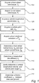
- Fig. 1 is a flow chart outlining the general steps of a method for estimating friction between a tire of a vehicle and a road surface according to an embodiment of the invention.
- the method comprises acquiring:
- the described method for determining tire/road friction is based on an analytical model which models the physics between the slip and the force.
- a model is provided which determines vehicle velocity taking the vehicle pitch into account.
- the model assumes access to standard vehicle dynamics sensors such as wheel speed signals from an ABS system and the longitudinal acceleration from an Inertial Measurement Unit (IMU) as well as access to measurements of the vehicle pitch rate from a pitch rate sensor such as the IMU.
- IMU Inertial Measurement Unit
- v x P 1 v x P 2 v x P 3 v x P 4 v x ⁇ w f ⁇ z cos ⁇ f + v y + l f ⁇ z sin ⁇ f v x + w f ⁇ z cos ⁇ f + v y + l f ⁇ z sin ⁇ f v x ⁇ w r ⁇ z cos ⁇ r + v y ⁇ l r ⁇ z sin ⁇ f v x ⁇ w r ⁇ z cos ⁇ r + v y ⁇ l r ⁇ z sin ⁇ r v x + w r ⁇ z cos ⁇ r + v y ⁇ l r ⁇ z sin ⁇ r v x + w r ⁇ z cos ⁇ r + v y ⁇ l r ⁇ z
- k i is the longitudinal tire stiffness parameter and ⁇ i is the friction coefficient
- f i is the normalized (with respect to the wheel normal force) force.
- Tire stiffness varies for different tires and the stiffness can change, for example through tire wear. However, tire wear is a slowly changing process and in the current context the tire stiffness k i can be considered to be constant. However, since car users may change tires to unknowns types, the stiffness need to be estimated onboard the vehicle. This is done by estimating the linear relationship between tire force and slip for small forces. The good thing is that stiffness not is dependent on friction for low forces, which makes the estimation of stiffness straightforward. Low forces can here be estimated as forces of up to 30% of the maximum force.
- the brush-model is derived from physical considerations.
- the longitudinal stiffness is considered known in the sense that it can be adapted from data using data where force utilization is low. In particular, at low forces the tire force is dependent on slip but not on the friction. Thereby, the longitudinal stiffness can be determined for low forces and once the longitudinal stiffness is known the friction can be determined when the wheel forces are higher, e.g. higher than 30% of a maximum force.
- the front and rear effective wheel radius can be considered known in the sense that it can be adapted from known data.
- the sensor data that feeds the proposed algorithm is:
- h is the height of the center of gravity of the vehicle, which can be assumed to be known with sufficient precision
- g is the gravitational constant
- m is the nominal mass of the vehicle, also assumed known with sufficient precision.
- pitch angle has to be estimated, which leads to the conclusion that pitch-rate sensing is essential for accurate estimation of the longitudinal velocity.
- the model for the pitch-rate sensor signal is: ⁇ ⁇ y ⁇ ⁇ y .
- the friction coefficient can be estimated based on a torque estimation, a force estimation and a stiffness estimation as illustrated schematically in Fig. 2 where the general flow of calculations can be described as pitch rate ⁇ pitch angle ⁇ vehicle velocity ⁇ tire longitudinal slip ⁇ friction.
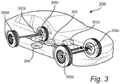
- Fig. 3 schematically illustrate a vehicle 300 comprising a system configured to determine tire-to-road friction.
- the system comprises a wheel axle torque sensing arrangement 302a-b configured to detect a front and rear wheel axle torque, an acceleration sensor 304 configured to detect a vehicle longitudinal acceleration and a pitch rate sensor 304 configured to detect a pitch rate of the vehicle.
- the acceleration sensor and pitch rate sensor are illustrated as one inertial measurement unit, IMU.
- the system also comprises a plurality of rotational velocity sensors 306a-d configured to detect a wheel rotational velocity of a respective one of each of the four wheels.
- the above mentioned sensors are connected to an a electronic control unit (ECU) 308 which in turn is configured to acquire a front wheel axle torque, a rear wheel axle torque, a vehicle longitudinal acceleration, a vehicle pitch rate and wheel rotational velocities from the sensors.
- ECU electronice control unit
- the electrical control unit 308 is further configured to: determine a front and rear wheel normal force based on a center of gravity of the vehicle and the longitudinal acceleration, determine a longitudinal tire stiffness, jointly determine a vehicle longitudinal velocity based on the wheel rotational velocities and vehicle longitudinal acceleration, and a vehicle pitch angle relative to the horizontal plane based on the vehicle pitch rate.
- a friction coefficient, ⁇ i between a wheel and ground can be determined based on the front and rear wheel axle torque, the front wheel normal force and the joint estimation of pitch angle and vehicle longitudinal velocity.
Description
- The present invention relates to a method and system for determining friction between the ground and a tire of a vehicle.
- Vehicle motion is highly dependent on the friction coefficient, i.e. the friction between the tires and ground. Therefore an accurate estimate of friction is valuable for many active safety functions such as collision avoidance. For example if low tire-to-road friction can be detected, the driver can be alerted, brake intervention can be performed earlier and the risk of collision and serious injuries can thereby be decreased. It is also expected that autonomous driving will require accurate friction estimation to adapt vehicle speed automatically, where driving fast on low friction surfaces could cause hazards such as skidding.
- Since it is typically both difficult and costly to directly measure friction, the research society and car industry has been focusing on technologies where the tire itself acts as the friction "sensor". That is, by utilizing vehicle dynamics models which relate e.g. tire slip and force as a function of friction, together with motion sensors such as inertial measurement units, wheel-speed sensors, etc., friction can be estimated.
-
US2005/0033499 discloses a method for estimating the road-to-tire friction in order for a collision avoidance system to adapt to current road friction conditions. In the method described inUS2005/0033499 , wheels are actively excited by applying an opposing torque to wheels on the respective first and second axle. - The document
US 2012/029783 discloses a vehicle wherein a model computing means has, a wheel ground contact load estimator, which finds a ground contact load estimated value of each wheel, a wheel friction force estimator, which finds a driving/braking force estimated value, which is the estimated value of a component in the x-axis direction of the wheel two-dimensional road surface reaction force on the wheel coordinate system of each wheel, and a lateral force estimated value. In D1, a road surface slope angle is the inclination angle of a road surface relative to a horizontal plane, as observed in the direction of the pitch axis of the vehicle. - However, a major limitation of current slip-force based estimation technologies is that estimation of slip is very difficult to perform in the case where all wheels experience longitudinal wheel forces e.g. during braking and/or all-wheel drive. Moreover, many existing friction estimation algorithms are active only during aggressive maneuvers, e.g. during acceleration or braking or cornering. The problem is also to estimate friction coefficient during low force excitement of the tires.
- Accordingly, there is a need for an improved system and method for determining tire-to-road friction in a vehicle.
- In view of above-mentioned and other drawbacks of the prior art, it is an object of the present invention to provide an improved method and system for determining road/surface friction in a vehicle.
- According to a first aspect of the invention, there is provided a method for estimating friction between a tire of a vehicle and a road surface, the method comprising acquiring:
- a front wheel axle torque, Tf ;
- a rear wheel axle torque, Tr ;
- a vehicle longitudinal acceleration, ax ;
- a vehicle pitch rate, Ω y ; and
- wheel rotational velocities, ωm f/r .
- The method further comprises determining a front wheel normal force, Fzf and a rear wheel normal force, Fzr , based on a center of gravity of the vehicle and the longitudinal acceleration; determining a longitudinal tire stiffness, ki ; jointly determining a vehicle longitudinal velocity, vx , based on the wheel rotational velocities and vehicle longitudinal acceleration, and a vehicle pitch angle, θ y , relative to the horizontal plane based on the vehicle pitch rate; and determining a friction coefficient, µi , between tires and ground based on the front and rear wheel axle torque, the front wheel normal force and the joint estimation of pitch angle and vehicle longitudinal velocity.
- A particular problem related to friction coefficient estimation, is that as it is described in the literature, it requires vehicle speed information. However, vehicle speed is very hard to estimate when all wheels are either braked or propelled since all wheels can be assumed to have a high amount of wheel slip, and hence wheel speed sensors gives less information about vehicle speed. The proposed invention solves this issue with a minimum of restrictive assumptions.
- That the vehicle longitudinal velocity is determined jointly with the vehicle pitch angle rate should in the present context be understood as an interdependent determination of the two parameters as will be described in the following.
- In particular, the present invention is based on the realization that by using a pitch-rate sensor the vehicle pitch angle can be estimated with sufficient accuracy. The pitch angle is crucial to in turn estimate the vehicle speed over ground, since the contamination of gravity of the vehicle's accelerometers can be cancelled using the information about the vehicle pitch. The vehicle speed is required for estimating the tire longitudinal slip. The core of the friction estimating method is that tire slip and wheel torque is estimated and by using a model, selects the best fit data. An improved accuracy of the wheel slip will in turn improve the friction estimate and at the same time provide an accurate pitch angle estimate.
- According to one embodiment of the invention, the friction coefficient may be determined based on a complete state dynamics model according to


- According to one embodiment of the invention, the function g is described by a brush model.
- According to one embodiment of the invention the center of gravity of the vehicle may be determined based on a known vehicle geometry. Thereby, there is no need to determine the center of gravity for a given vehicle in advance.
- According to one embodiment of the invention, the vehicle longitudinal acceleration and the vehicle pitch rate may be acquired from an inertial measurement unit, IMU. Thereby, a sensor arrangement which is commonly available in vehicles can be used to determine the pitch rate. This brings the advantage that the described method can be used also in existing vehicles which are not previously equipped with the tire/road friction determination functionality.
- According to one embodiment of the invention, determining a wheel axel torque may comprise determining a brake torque based on a hydraulic brake pressure and determining an engine torque based on a mass flow and a fuel flow of a combustion engine of the vehicle. Accordingly, wheel axle torque can be determined using sensors which are already used for other purposes, and there is thus no need for dedicated wheel torque sensors. Accordingly, the described method may in principle be used in already existing vehicle with a minimum of retrofitting or upgrades required. Moreover, for electrical or hybrid vehicles, the wheel axle torque may also be determined based on a torque provided to the axle by an electrical machine.
- According to a second aspect of the invention, there is provided a tire-road friction determination system in a vehicle, the system comprising: a wheel axle torque sensing arrangement configured to detect a front and rear wheel axle torque; an acceleration sensor configured to detect a vehicle longitudinal acceleration; a pitch rate sensor configured to detect a pitch rate of the vehicle; at least one rotational velocity sensor configured to detect a wheel rotational velocity of at least one wheel; and an electronic control unit (ECU) configured to acquire:
- a front wheel axle torque, Tf ;
- a rear wheel axle torque, Tr ;
- a vehicle longitudinal acceleration, ax ;
- a vehicle pitch rate, Ω y ; and
- wheel rotational velocities, ωm f/r ;
- According to one embodiment of the invention the pitch rate sensor may comprise an inertial measurement unit, IMU. The IMU may comprise one or more accelerometers, gyroscopes, magnetometers and/or any combination thereof. Moreover, the sensor used to determine the pitch rate may be a dedicated pitch rate sensor or a general purpose sensor such as an IMU used also for other functions of a vehicle.
- According to one embodiment of the invention the wheel axel torque sensing arrangement may comprise at least one hydraulic brake pressure sensor configured to determine a brake torque of each wheel and a mass flow sensor and a fuel flow sensor configured to determine an engine torque provided to each of said wheels based on a mass flow and a fuel flow of a combustion engine of the vehicle. However, it is also possible to use dedicated torque sensors arranged on the respective wheel axles to determine the respective wheel axle torques.
- Further effects and features of the second aspect of the invention are largely analogous to those described above in connection with the first aspect of the invention.
- Further features of, and advantages with, the present invention will become apparent when studying the appended claims and the following description. The skilled person realize that different features of the present invention may be combined to create embodiments other than those described in the following, without departing from the scope of the present invention.
- These and other aspects of the present invention will now be described in more detail, with reference to the appended drawings showing an example embodiment of the invention, wherein:
-
Fig 1 is a flow chart outlining the general steps of a method according to an embodiment of the invention; -
Fig. 2 is a block chart outlining general features of the present invention; and -
Fig. 3 is a schematic illustration of a vehicle comprising a system according to an embodiment of the invention. - In the present detailed description, various embodiments of the method and according to the present invention will be described.
-
Fig. 1 is a flow chart outlining the general steps of a method for estimating friction between a tire of a vehicle and a road surface according to an embodiment of the invention. - The method comprises acquiring:
- a front wheel axle torque,
T f 102; - a rear wheel axle torque,
T r 104; - a vehicle longitudinal acceleration, ax 106;
- a vehicle pitch rate,
Ω y 108; and - wheel rotational velocities,
ω m f/r 110. - The described method for determining tire/road friction is based on an analytical model which models the physics between the slip and the force. In particular, a model is provided which determines vehicle velocity taking the vehicle pitch into account.
- The model assumes access to standard vehicle dynamics sensors such as wheel speed signals from an ABS system and the longitudinal acceleration from an Inertial Measurement Unit (IMU) as well as access to measurements of the vehicle pitch rate from a pitch rate sensor such as the IMU.
- In the following, signal processing algorithms for estimation of the tire/road friction coefficient will be described in further detail. First, information related to wheel velocities is derived. The vehicle geometry is as follows:
- lf : Longitudinal distance from center of gravity to the front axle.
- lr : Longitudinal distance from center of gravity to the rear axle.
- wf : Half front track width.
- wr : Half rear track width.
- It is assumed that the vehicle is moving in the plane and that the longitudinal and lateral vehicle velocity expressed in the center-of-gravity coordinate system is vx and vy , respectively. It is further assumed that the vehicle yaw-rate is Ωz. The basic relation used next is that the velocity vector vP at a point P which is rotating with rate Ω z relative the center-of-gravity coordinate system is:


- Assume further that the front and rear wheels have steering angles δf and δr , respectively. The longitudinal component of the wheel velocity in the local tire coordinate system P i is thus related to the vehicle center of gravity velocities as:

- Here it is assumed that the left and right front/rear wheel angles are identical. In the following it is assumed assume for simplicity that the rear wheel angle is zero.
- The longitudinal wheel slip is defined as:

- Next the relation between longitudinal tire slip and the applied normalized longitudinal tire force is considered. Although it is theoretically possible to extend the results to the case with so-called combined slip, this will not be described herein. In the literature an abundance of models relating the wheel slip si and the applied normalized traction force fi can be found. In the current analysis only static models are considered.
- A tire-force model common in the field of vehicle dynamics is the "brush-model" with parabolic normal load distribution, which states:

- Here ki is the longitudinal tire stiffness parameter and µi is the friction coefficient, and fi is the normalized (with respect to the wheel normal force) force. Tire stiffness varies for different tires and the stiffness can change, for example through tire wear. However, tire wear is a slowly changing process and in the current context the tire stiffness ki can be considered to be constant. However, since car users may change tires to unknowns types, the stiffness need to be estimated onboard the vehicle. This is done by estimating the linear relationship between tire force and slip for small forces. The good thing is that stiffness not is dependent on friction for low forces, which makes the estimation of stiffness straightforward. Low forces can here be estimated as forces of up to 30% of the maximum force.
- The brush-model is derived from physical considerations. An example among many candidates of a "curve-fitting-like" non-physical tire-force model is

- The exact form of the tire-force model is not critical for the development below. Hence, in the following it is simply assumed that the following static tire-force models are available:

- The basic relation utilized here is that the dynamics of the wheel speed signals are given by:


- For simplicity only one side of the vehicle is studied. Here, the following parameters are assumed to be known with sufficient precision:
- Jwf = front wheel inertia
- Jwr = rear wheel inertia
- tire parameters such as longitudinal stiffness in the brush model
- r f/r : front and rear effective wheel radius.
- Note that the longitudinal stiffness is considered known in the sense that it can be adapted from data using data where force utilization is low. In particular, at low forces the tire force is dependent on slip but not on the friction. Thereby, the longitudinal stiffness can be determined for low forces and once the longitudinal stiffness is known the friction can be determined when the wheel forces are higher, e.g. higher than 30% of a maximum force.
- The front and rear effective wheel radius can be considered known in the sense that it can be adapted from known data.
- The state vector (quantities that are to be estimated) for the problem at hand is defined as:

- The embodiment described presented herein is focused on the case where the vehicle is travelling in a more or less straight line. This assumption is made to simplify the analysis to a suitable extent.
- The sensor data that feeds the proposed algorithm is:
- Tf front wheel axle torque
- Tr rear wheel axle torque
- ax : longitudinal acceleration acquired from the IMU
- Ω y : pitch rate acquired from the IMU
- Fzf : front wheel normal force
- Fzr : rear wheel normal force
- ωm f/r : measured wheel rotational velocities.
- It can be noted that there is no sensor available that directly measures the tire normal forces. Instead it is assumed that wheel normal forces can be estimated using standard assumptions on static torque equilibrium around a pitch axis through center of gravity known by the skilled person.


- Here h is the height of the center of gravity of the vehicle, which can be assumed to be known with sufficient precision, g is the gravitational constant, and m is the nominal mass of the vehicle, also assumed known with sufficient precision. The above expression can easily be modified to include also the air-resistance by a person skilled in the art.
- One problem related to the current analysis is as follows. Assume that the vehicle applies torques T f/r on the front and/or rear axle and as a result, the wheel rotational velocity changes. However, the change rate will depend on at least the friction. While driving on ice, a small change in applied torque results in a large change in wheel rotational speed. If all wheel rotational velocities are affected by slip then the estimation of the vehicle's longitudinal velocity is difficult. In an attempt to mitigate the problem one can consider to integrate the longitudinal acceleration for estimation of vx ., As long as the vehicle is on flat ground this could work; but in general the problem is that the gravity vector affects the reading of the longitudinal acceleration (valid as long as the vehicle is travelling straight ahead):

- Thus, for estimation of the longitudinal velocity using integration, also pitch angle has to be estimated, which leads to the conclusion that pitch-rate sensing is essential for accurate estimation of the longitudinal velocity. As long as the vehicle is travelling straight ahead, the model for the pitch-rate sensor signal is:

- In conclusion, the non-linear complete state dynamics model for the problem at hand is:


- Based on the above described modelling, the friction coefficient can be estimated based on a torque estimation, a force estimation and a stiffness estimation as illustrated schematically in
Fig. 2 where the general flow of calculations can be described as pitch rate → pitch angle → vehicle velocity → tire longitudinal slip → friction. - The modelling described above has defined the equations that govern the state dynamics, and it has been specified which sensor data that is assumed available. The exact choice of non-linear filtering algorithm used can be considered to be less important since this a standard topic for the person skilled in the art.
-
Fig. 3 schematically illustrate avehicle 300 comprising a system configured to determine tire-to-road friction. The system comprises a wheel axletorque sensing arrangement 302a-b configured to detect a front and rear wheel axle torque, anacceleration sensor 304 configured to detect a vehicle longitudinal acceleration and apitch rate sensor 304 configured to detect a pitch rate of the vehicle. Here the acceleration sensor and pitch rate sensor are illustrated as one inertial measurement unit, IMU. The system also comprises a plurality ofrotational velocity sensors 306a-d configured to detect a wheel rotational velocity of a respective one of each of the four wheels. The above mentioned sensors are connected to an a electronic control unit (ECU) 308 which in turn is configured to acquire a front wheel axle torque, a rear wheel axle torque, a vehicle longitudinal acceleration, a vehicle pitch rate and wheel rotational velocities from the sensors. - Based on the acquired information, the
electrical control unit 308 is further configured to: determine a front and rear wheel normal force based on a center of gravity of the vehicle and the longitudinal acceleration, determine a longitudinal tire stiffness, jointly determine a vehicle longitudinal velocity based on the wheel rotational velocities and vehicle longitudinal acceleration, and a vehicle pitch angle relative to the horizontal plane based on the vehicle pitch rate. Thereby a friction coefficient, µi , between a wheel and ground can be determined based on the front and rear wheel axle torque, the front wheel normal force and the joint estimation of pitch angle and vehicle longitudinal velocity. - Even though the invention has been described with reference to specific exemplifying embodiments thereof, many different alterations, modifications and the like will become apparent for those skilled in the art. Also, it should be noted that parts of the method and system may be omitted, interchanged or arranged in various ways, the method and system yet being able to perform the functionality of the present invention.
- Additionally, variations to the disclosed embodiments can be understood and effected by the skilled person in practicing the claimed invention, from a study of the drawings, the disclosure, and the appended claims. In the claims, the word "comprising" does not exclude other elements or steps, and the indefinite article "a" or "an" does not exclude a plurality. The mere fact that certain measures are recited in mutually different dependent claims does not indicate that a combination of these measures cannot be used to advantage.
Claims (11)
- A method for estimating friction between a tire of a vehicle and a road surface, the method comprising:acquiring:- a front wheel axle torque, Tf (102);- a rear wheel axle torque, Tr (104);- a vehicle longitudinal acceleration, ax (106);- a vehicle pitch rate, Ω y (108); and- a plurality of wheel rotational velocities, ωm f/r (110);determining (112) a front wheel normal force, Fzf and a rear wheel normal force, Fzr , based on a center of gravity of the vehicle and the longitudinal acceleration;determining (114) a longitudinal tire stiffness, ki ;jointly determining (116) a vehicle longitudinal velocity, vx , based on the wheel rotational velocities and vehicle longitudinal acceleration, and a vehicle pitch angle, θ y , relative to the horizontal plane based on the vehicle pitch rate; anddetermining (118) a friction coefficient, µi , between a tire and the road surface based on the front and rear wheel axle torque, the front wheel normal force and the joint estimation of the pitch angle and the vehicle longitudinal velocity.
- The method according to claim 1, wherein the friction coefficient is determined based on a complete state dynamics model according to


- The method according to claim 2, wherein the function g is described by a brush model.
- The method according to any one of the preceding claims, wherein the center of gravity of the vehicle is determined based on a known vehicle geometry.
- The method according to any one of the preceding claims, wherein the vehicle longitudinal acceleration and the vehicle pitch rate is acquired from an inertial measurement unit, IMU.
- The method according to any one of the preceding claims, wherein determining a wheel axel torque comprises determining a brake torque based on a hydraulic brake pressure and determining an engine torque based on a mass flow and a fuel flow of a combustion engine of said vehicle.
- A tire-road friction determination system in a vehicle, the system comprising:a wheel axle torque sensing arrangement (302a-b) configured to detect a front and rear wheel axle torque;an acceleration sensor (304) configured to detect a vehicle longitudinal acceleration;a pitch rate sensor (304) configured to detect a pitch rate of the vehicle;at least one rotational velocity sensor (306a-d) configured to detect a wheel rotational velocity of at least one wheel; andan a electronic control unit (308) configured to acquire:- a front wheel axle torque, Tf ;- a rear wheel axle torque, Tr ;- a vehicle longitudinal acceleration, ax ;- a vehicle pitch rate, Ω y ; and- wheel rotational velocities, ωm f/r ;the electrical control unit being further configured to:determine a front wheel normal force, Fzf and a rear wheel normal force, Fzr , based on a center of gravity of the vehicle and the longitudinal acceleration;determine a longitudinal tire stiffness, ki ;jointly determine a vehicle longitudinal velocity, vx , based on the wheel rotational velocities and vehicle longitudinal acceleration, and a vehicle pitch angle relative to the horizontal plane based on the vehicle pitch rate; anddetermine a friction coefficient, µi , between a wheel and ground based on the front and rear wheel axle torque, the front wheel normal force and the joint estimation of pitch angle and vehicle longitudinal velocity.
- The system according to claim 7, wherein the electronic control unit is further configured to determine the friction coefficient based on a complete state dynamics model according to


- The system according to claim 7 or 8, wherein the pitch rate sensor comprises an inertial measurement unit, IMU.
- The system according to any one of claims 7 to 9, wherein the wheel axel torque sensing arrangement comprises:at least one hydraulic brake pressure sensor configured to determine a brake torque of each wheel; anda mass flow sensor and a fuel flow sensor configured to determine an engine torque provided to each of said wheels based on a mass flow and a fuel flow of a combustion engine of said vehicle.
- A vehicle comprising a tire-road friction determination system according to any one of claims 7 to 10.
Priority Applications (3)
| Application Number | Priority Date | Filing Date | Title |
|---|---|---|---|
| EP16193753.7A EP3309024B1 (en) | 2016-10-13 | 2016-10-13 | Method and system for determining friction between the ground and a tire of a vehicle |
| CN201710902914.0A CN107933563B (en) | 2016-10-13 | 2017-09-28 | Method and system for determining friction between ground and vehicle tires |
| US15/726,871 US10632978B2 (en) | 2016-10-13 | 2017-10-06 | Method and system for determining friction between the ground and a tire of a vehicle |
Applications Claiming Priority (1)
| Application Number | Priority Date | Filing Date | Title |
|---|---|---|---|
| EP16193753.7A EP3309024B1 (en) | 2016-10-13 | 2016-10-13 | Method and system for determining friction between the ground and a tire of a vehicle |
Publications (2)
| Publication Number | Publication Date |
|---|---|
| EP3309024A1 EP3309024A1 (en) | 2018-04-18 |
| EP3309024B1 true EP3309024B1 (en) | 2020-12-16 |
Family
ID=57137902
Family Applications (1)
| Application Number | Title | Priority Date | Filing Date |
|---|---|---|---|
| EP16193753.7A Active EP3309024B1 (en) | 2016-10-13 | 2016-10-13 | Method and system for determining friction between the ground and a tire of a vehicle |
Country Status (3)
| Country | Link |
|---|---|
| US (1) | US10632978B2 (en) |
| EP (1) | EP3309024B1 (en) |
| CN (1) | CN107933563B (en) |
Families Citing this family (11)
| Publication number | Priority date | Publication date | Assignee | Title |
|---|---|---|---|---|
| JP6694959B2 (en) * | 2015-12-18 | 2020-05-20 | ニラ・ダイナミクス・エイビイ | Estimating tire stiffness and road friction |
| JP6948157B2 (en) * | 2017-05-24 | 2021-10-13 | 川崎重工業株式会社 | Vehicle control device |
| DE102017219048A1 (en) * | 2017-10-25 | 2019-04-25 | Robert Bosch Gmbh | Method and device for determining a state of a roadway of a vehicle |
| EP3850305B1 (en) * | 2018-09-14 | 2024-03-06 | Uatc, Llc | Driving surface friction estimations for vehicles |
| DE102018220576A1 (en) * | 2018-11-29 | 2020-06-04 | Robert Bosch Gmbh | Method and control device for determining a coefficient of friction potential of a road surface |
| CN110843788A (en) * | 2019-10-30 | 2020-02-28 | 同济大学 | Vehicle condition analysis method based on road surface friction coefficient |
| KR20210057872A (en) * | 2019-11-12 | 2021-05-24 | 현대자동차주식회사 | Eco-friendly vehicle and motor torque control method thereof |
| CN113978470B (en) * | 2021-12-13 | 2024-01-12 | 郑州轻工业大学 | On-line quick estimation method for friction force between tire and road surface |
| CN114834408B (en) * | 2022-03-14 | 2023-03-24 | 湖南速特智能科技有限公司 | Automobile braking method and system |
| CN114355952B (en) * | 2022-03-17 | 2022-06-17 | 北京理工大学 | Unmanned vehicle trafficability assessment method and system |
| CN114643962B (en) * | 2022-03-31 | 2023-03-14 | 上汽通用五菱汽车股份有限公司 | Vehicle brake control method and device and computer equipment |
Family Cites Families (22)
| Publication number | Priority date | Publication date | Assignee | Title |
|---|---|---|---|---|
| JP4114044B2 (en) * | 2001-07-17 | 2008-07-09 | トヨタ自動車株式会社 | Tire acting force detection device |
| EP1481861B1 (en) | 2003-05-28 | 2007-07-04 | Ford Global Technologies, LLC | A method and a computer readable storage device for estimating tirc-to-road friction |
| US20050038589A1 (en) * | 2003-08-14 | 2005-02-17 | Deepak Shukla | Method for estimating a friction coefficient |
| US20050038588A1 (en) * | 2003-08-14 | 2005-02-17 | Deepak Shukla | Vehicle driving force control method |
| JP4213545B2 (en) * | 2003-09-05 | 2009-01-21 | 株式会社ジェイテクト | Wheel grip degree estimation device, and vehicle motion control device including the device |
| US20080228329A1 (en) * | 2007-03-13 | 2008-09-18 | Honeywell International Inc. | Methods and systems for friction detection and slippage control |
| EP2147842A4 (en) * | 2007-04-17 | 2014-05-14 | Nissan Motor | Device and method for estimating frictional condition of ground contact surface of wheel |
| JP5096781B2 (en) * | 2007-04-18 | 2012-12-12 | 富士重工業株式会社 | Vehicle road friction coefficient estimation device |
| DE102007053256B3 (en) * | 2007-11-08 | 2009-07-09 | Continental Automotive Gmbh | Method and device for determining a coefficient of friction |
| EP2295301A4 (en) * | 2008-06-30 | 2014-07-09 | Nissan Motor | Road surface friction coefficient estimating device and road surface friction coefficient estimating method |
| RU2468945C1 (en) * | 2008-10-29 | 2012-12-10 | Ниссан Мотор Ко., Лтд. | Device and method for estimating friction of earth surface in contact with transport facility |
| US20100114431A1 (en) * | 2008-10-31 | 2010-05-06 | Volkswagen Group Of America, Inc. | Method for Controlling Vehicle Dynamics |
| US8055424B2 (en) * | 2008-11-21 | 2011-11-08 | GM Global Technology Operations LLC | Real-time identification of maximum tire-road friction coefficient by induced wheels acceleration/deceleration |
| JP5133917B2 (en) * | 2009-02-16 | 2013-01-30 | 本田技研工業株式会社 | Road friction coefficient estimation device |
| EP2394876B1 (en) * | 2009-03-30 | 2014-10-15 | Honda Motor Co., Ltd. | Device for estimating state quantity of skid motion of vehicle |
| JP5172764B2 (en) * | 2009-03-30 | 2013-03-27 | 本田技研工業株式会社 | Road friction coefficient estimation device |
| DE102012222489A1 (en) * | 2012-12-06 | 2014-06-12 | Continental Teves Ag & Co. Ohg | Method for controlling the driving dynamics |
| JP6012523B2 (en) * | 2013-03-25 | 2016-10-25 | 日立建機株式会社 | Construction vehicle |
| DE102014213663B4 (en) * | 2013-07-15 | 2024-04-11 | Magna Powertrain Of America, Inc. | Traction control system for four-wheel/all-wheel drive vehicles with on-board camera |
| US9340211B1 (en) * | 2014-12-03 | 2016-05-17 | The Goodyear Tire & Rubber Company | Intelligent tire-based road friction estimation system and method |
| US9707967B2 (en) * | 2015-06-30 | 2017-07-18 | Kelsey-Hayes Company | Method of traction control for a motor vehicle |
| DE102016214574B4 (en) * | 2016-08-05 | 2019-08-29 | Volkswagen Aktiengesellschaft | Method and device for estimating the coefficient of friction of a wheel of a vehicle relative to a ground |
-
2016
- 2016-10-13 EP EP16193753.7A patent/EP3309024B1/en active Active
-
2017
- 2017-09-28 CN CN201710902914.0A patent/CN107933563B/en active Active
- 2017-10-06 US US15/726,871 patent/US10632978B2/en active Active
Non-Patent Citations (1)
| Title |
|---|
| None * |
Also Published As
| Publication number | Publication date |
|---|---|
| CN107933563A (en) | 2018-04-20 |
| EP3309024A1 (en) | 2018-04-18 |
| CN107933563B (en) | 2021-05-07 |
| US10632978B2 (en) | 2020-04-28 |
| US20180105151A1 (en) | 2018-04-19 |
Similar Documents
| Publication | Publication Date | Title |
|---|---|---|
| EP3309024B1 (en) | Method and system for determining friction between the ground and a tire of a vehicle | |
| EP3106360B1 (en) | Method and arrangement for tire to road friction estimation | |
| CN101657345B (en) | Device and method for estimating frictional condition of ground contact surface of wheel | |
| US10710597B2 (en) | Method and system for computing a road friction estimate | |
| CN105829185B (en) | Potential adhesive force is estimated by assessment rolling radius | |
| US6473682B2 (en) | Apparatus and method for estimating maximum road friction coefficient | |
| US20140371990A1 (en) | Sensor system comprising a vehicle model unit | |
| US20190368878A1 (en) | Method for determining an orientation of a vehicle | |
| EP3398825A1 (en) | Method and system for computing a road friction estimate | |
| US20030163237A1 (en) | Method of controlling traveling stability of vehicle | |
| CN105073526A (en) | Method for determining a vehicle reference speed and vehicle controller having such a method | |
| CN107933562B (en) | Method and system for calculating road friction estimates | |
| JPH09249010A (en) | Initial correction coefficient arithmetic unit and device using the unit | |
| Ding et al. | Application of recursive least square algorithm on estimation of vehicle sideslip angle and road friction | |
| Hu et al. | Tire-road friction coefficient estimation under constant vehicle speed control | |
| CN114787014A (en) | On-board road friction estimation | |
| Jiang et al. | Real-time estimation and prediction of tire forces using digital map for driving risk assessment | |
| US20190389473A1 (en) | Method and apparatus for accelerometer based tire normal force estimation | |
| CN113226881A (en) | Vehicle motion state estimation device, vehicle motion state estimation method, and vehicle | |
| JPH11180274A (en) | Attitude control device of vehicle | |
| EP3800116B1 (en) | Tire force estimating device and tire force estimating method | |
| JPH11115720A (en) | Estimation device of road surface friction coefficient | |
| JP3535358B2 (en) | Road friction coefficient estimation device | |
| Ghandour et al. | Risk indicators anticipation based on the vehicle dynamics anticipation to avoid accidents | |
| RU2812026C1 (en) | Method for determining angular velocity of additional yaw of wheels of road train |
Legal Events
| Date | Code | Title | Description |
|---|---|---|---|
| PUAI | Public reference made under article 153(3) epc to a published international application that has entered the european phase |
Free format text: ORIGINAL CODE: 0009012 |
|
| STAA | Information on the status of an ep patent application or granted ep patent |
Free format text: STATUS: THE APPLICATION HAS BEEN PUBLISHED |
|
| AK | Designated contracting states |
Kind code of ref document: A1 Designated state(s): AL AT BE BG CH CY CZ DE DK EE ES FI FR GB GR HR HU IE IS IT LI LT LU LV MC MK MT NL NO PL PT RO RS SE SI SK SM TR |
|
| AX | Request for extension of the european patent |
Extension state: BA ME |
|
| STAA | Information on the status of an ep patent application or granted ep patent |
Free format text: STATUS: REQUEST FOR EXAMINATION WAS MADE |
|
| 17P | Request for examination filed |
Effective date: 20181018 |
|
| RBV | Designated contracting states (corrected) |
Designated state(s): AL AT BE BG CH CY CZ DE DK EE ES FI FR GB GR HR HU IE IS IT LI LT LU LV MC MK MT NL NO PL PT RO RS SE SI SK SM TR |
|
| GRAP | Despatch of communication of intention to grant a patent |
Free format text: ORIGINAL CODE: EPIDOSNIGR1 |
|
| STAA | Information on the status of an ep patent application or granted ep patent |
Free format text: STATUS: GRANT OF PATENT IS INTENDED |
|
| INTG | Intention to grant announced |
Effective date: 20200729 |
|
| GRAS | Grant fee paid |
Free format text: ORIGINAL CODE: EPIDOSNIGR3 |
|
| GRAA | (expected) grant |
Free format text: ORIGINAL CODE: 0009210 |
|
| STAA | Information on the status of an ep patent application or granted ep patent |
Free format text: STATUS: THE PATENT HAS BEEN GRANTED |
|
| AK | Designated contracting states |
Kind code of ref document: B1 Designated state(s): AL AT BE BG CH CY CZ DE DK EE ES FI FR GB GR HR HU IE IS IT LI LT LU LV MC MK MT NL NO PL PT RO RS SE SI SK SM TR |
|
| REG | Reference to a national code |
Ref country code: GB Ref legal event code: FG4D |
|
| REG | Reference to a national code |
Ref country code: DE Ref legal event code: R096 Ref document number: 602016049784 Country of ref document: DE |
|
| REG | Reference to a national code |
Ref country code: IE Ref legal event code: FG4D |
|
| REG | Reference to a national code |
Ref country code: AT Ref legal event code: REF Ref document number: 1345324 Country of ref document: AT Kind code of ref document: T Effective date: 20210115 |
|
| PG25 | Lapsed in a contracting state [announced via postgrant information from national office to epo] |
Ref country code: RS Free format text: LAPSE BECAUSE OF FAILURE TO SUBMIT A TRANSLATION OF THE DESCRIPTION OR TO PAY THE FEE WITHIN THE PRESCRIBED TIME-LIMIT Effective date: 20201216 Ref country code: NO Free format text: LAPSE BECAUSE OF FAILURE TO SUBMIT A TRANSLATION OF THE DESCRIPTION OR TO PAY THE FEE WITHIN THE PRESCRIBED TIME-LIMIT Effective date: 20210316 Ref country code: FI Free format text: LAPSE BECAUSE OF FAILURE TO SUBMIT A TRANSLATION OF THE DESCRIPTION OR TO PAY THE FEE WITHIN THE PRESCRIBED TIME-LIMIT Effective date: 20201216 Ref country code: GR Free format text: LAPSE BECAUSE OF FAILURE TO SUBMIT A TRANSLATION OF THE DESCRIPTION OR TO PAY THE FEE WITHIN THE PRESCRIBED TIME-LIMIT Effective date: 20210317 |
|
| REG | Reference to a national code |
Ref country code: AT Ref legal event code: MK05 Ref document number: 1345324 Country of ref document: AT Kind code of ref document: T Effective date: 20201216 |
|
| REG | Reference to a national code |
Ref country code: NL Ref legal event code: MP Effective date: 20201216 |
|
| PG25 | Lapsed in a contracting state [announced via postgrant information from national office to epo] |
Ref country code: SE Free format text: LAPSE BECAUSE OF FAILURE TO SUBMIT A TRANSLATION OF THE DESCRIPTION OR TO PAY THE FEE WITHIN THE PRESCRIBED TIME-LIMIT Effective date: 20201216 Ref country code: LV Free format text: LAPSE BECAUSE OF FAILURE TO SUBMIT A TRANSLATION OF THE DESCRIPTION OR TO PAY THE FEE WITHIN THE PRESCRIBED TIME-LIMIT Effective date: 20201216 Ref country code: BG Free format text: LAPSE BECAUSE OF FAILURE TO SUBMIT A TRANSLATION OF THE DESCRIPTION OR TO PAY THE FEE WITHIN THE PRESCRIBED TIME-LIMIT Effective date: 20210316 |
|
| PG25 | Lapsed in a contracting state [announced via postgrant information from national office to epo] |
Ref country code: NL Free format text: LAPSE BECAUSE OF FAILURE TO SUBMIT A TRANSLATION OF THE DESCRIPTION OR TO PAY THE FEE WITHIN THE PRESCRIBED TIME-LIMIT Effective date: 20201216 Ref country code: HR Free format text: LAPSE BECAUSE OF FAILURE TO SUBMIT A TRANSLATION OF THE DESCRIPTION OR TO PAY THE FEE WITHIN THE PRESCRIBED TIME-LIMIT Effective date: 20201216 |
|
| REG | Reference to a national code |
Ref country code: LT Ref legal event code: MG9D |
|
| PG25 | Lapsed in a contracting state [announced via postgrant information from national office to epo] |
Ref country code: PT Free format text: LAPSE BECAUSE OF FAILURE TO SUBMIT A TRANSLATION OF THE DESCRIPTION OR TO PAY THE FEE WITHIN THE PRESCRIBED TIME-LIMIT Effective date: 20210416 Ref country code: SK Free format text: LAPSE BECAUSE OF FAILURE TO SUBMIT A TRANSLATION OF THE DESCRIPTION OR TO PAY THE FEE WITHIN THE PRESCRIBED TIME-LIMIT Effective date: 20201216 Ref country code: RO Free format text: LAPSE BECAUSE OF FAILURE TO SUBMIT A TRANSLATION OF THE DESCRIPTION OR TO PAY THE FEE WITHIN THE PRESCRIBED TIME-LIMIT Effective date: 20201216 Ref country code: EE Free format text: LAPSE BECAUSE OF FAILURE TO SUBMIT A TRANSLATION OF THE DESCRIPTION OR TO PAY THE FEE WITHIN THE PRESCRIBED TIME-LIMIT Effective date: 20201216 Ref country code: CZ Free format text: LAPSE BECAUSE OF FAILURE TO SUBMIT A TRANSLATION OF THE DESCRIPTION OR TO PAY THE FEE WITHIN THE PRESCRIBED TIME-LIMIT Effective date: 20201216 Ref country code: SM Free format text: LAPSE BECAUSE OF FAILURE TO SUBMIT A TRANSLATION OF THE DESCRIPTION OR TO PAY THE FEE WITHIN THE PRESCRIBED TIME-LIMIT Effective date: 20201216 Ref country code: LT Free format text: LAPSE BECAUSE OF FAILURE TO SUBMIT A TRANSLATION OF THE DESCRIPTION OR TO PAY THE FEE WITHIN THE PRESCRIBED TIME-LIMIT Effective date: 20201216 |
|
| PG25 | Lapsed in a contracting state [announced via postgrant information from national office to epo] |
Ref country code: AT Free format text: LAPSE BECAUSE OF FAILURE TO SUBMIT A TRANSLATION OF THE DESCRIPTION OR TO PAY THE FEE WITHIN THE PRESCRIBED TIME-LIMIT Effective date: 20201216 Ref country code: PL Free format text: LAPSE BECAUSE OF FAILURE TO SUBMIT A TRANSLATION OF THE DESCRIPTION OR TO PAY THE FEE WITHIN THE PRESCRIBED TIME-LIMIT Effective date: 20201216 |
|
| REG | Reference to a national code |
Ref country code: DE Ref legal event code: R097 Ref document number: 602016049784 Country of ref document: DE |
|
| PG25 | Lapsed in a contracting state [announced via postgrant information from national office to epo] |
Ref country code: IS Free format text: LAPSE BECAUSE OF FAILURE TO SUBMIT A TRANSLATION OF THE DESCRIPTION OR TO PAY THE FEE WITHIN THE PRESCRIBED TIME-LIMIT Effective date: 20210416 |
|
| PLBE | No opposition filed within time limit |
Free format text: ORIGINAL CODE: 0009261 |
|
| STAA | Information on the status of an ep patent application or granted ep patent |
Free format text: STATUS: NO OPPOSITION FILED WITHIN TIME LIMIT |
|
| PG25 | Lapsed in a contracting state [announced via postgrant information from national office to epo] |
Ref country code: AL Free format text: LAPSE BECAUSE OF FAILURE TO SUBMIT A TRANSLATION OF THE DESCRIPTION OR TO PAY THE FEE WITHIN THE PRESCRIBED TIME-LIMIT Effective date: 20201216 |
|
| 26N | No opposition filed |
Effective date: 20210917 |
|
| PG25 | Lapsed in a contracting state [announced via postgrant information from national office to epo] |
Ref country code: DK Free format text: LAPSE BECAUSE OF FAILURE TO SUBMIT A TRANSLATION OF THE DESCRIPTION OR TO PAY THE FEE WITHIN THE PRESCRIBED TIME-LIMIT Effective date: 20201216 |
|
| PG25 | Lapsed in a contracting state [announced via postgrant information from national office to epo] |
Ref country code: ES Free format text: LAPSE BECAUSE OF FAILURE TO SUBMIT A TRANSLATION OF THE DESCRIPTION OR TO PAY THE FEE WITHIN THE PRESCRIBED TIME-LIMIT Effective date: 20201216 |
|
| PG25 | Lapsed in a contracting state [announced via postgrant information from national office to epo] |
Ref country code: SI Free format text: LAPSE BECAUSE OF FAILURE TO SUBMIT A TRANSLATION OF THE DESCRIPTION OR TO PAY THE FEE WITHIN THE PRESCRIBED TIME-LIMIT Effective date: 20201216 |
|
| REG | Reference to a national code |
Ref country code: CH Ref legal event code: PL |
|
| PG25 | Lapsed in a contracting state [announced via postgrant information from national office to epo] |
Ref country code: IS Free format text: LAPSE BECAUSE OF FAILURE TO SUBMIT A TRANSLATION OF THE DESCRIPTION OR TO PAY THE FEE WITHIN THE PRESCRIBED TIME-LIMIT Effective date: 20210416 |
|
| REG | Reference to a national code |
Ref country code: BE Ref legal event code: MM Effective date: 20211031 |
|
| GBPC | Gb: european patent ceased through non-payment of renewal fee |
Effective date: 20211013 |
|
| PG25 | Lapsed in a contracting state [announced via postgrant information from national office to epo] |
Ref country code: MC Free format text: LAPSE BECAUSE OF FAILURE TO SUBMIT A TRANSLATION OF THE DESCRIPTION OR TO PAY THE FEE WITHIN THE PRESCRIBED TIME-LIMIT Effective date: 20201216 |
|
| PG25 | Lapsed in a contracting state [announced via postgrant information from national office to epo] |
Ref country code: LU Free format text: LAPSE BECAUSE OF NON-PAYMENT OF DUE FEES Effective date: 20211013 Ref country code: GB Free format text: LAPSE BECAUSE OF NON-PAYMENT OF DUE FEES Effective date: 20211013 Ref country code: BE Free format text: LAPSE BECAUSE OF NON-PAYMENT OF DUE FEES Effective date: 20211031 |
|
| PG25 | Lapsed in a contracting state [announced via postgrant information from national office to epo] |
Ref country code: LI Free format text: LAPSE BECAUSE OF NON-PAYMENT OF DUE FEES Effective date: 20211031 Ref country code: CH Free format text: LAPSE BECAUSE OF NON-PAYMENT OF DUE FEES Effective date: 20211031 |
|
| PG25 | Lapsed in a contracting state [announced via postgrant information from national office to epo] |
Ref country code: IE Free format text: LAPSE BECAUSE OF NON-PAYMENT OF DUE FEES Effective date: 20211013 |
|
| PG25 | Lapsed in a contracting state [announced via postgrant information from national office to epo] |
Ref country code: HU Free format text: LAPSE BECAUSE OF FAILURE TO SUBMIT A TRANSLATION OF THE DESCRIPTION OR TO PAY THE FEE WITHIN THE PRESCRIBED TIME-LIMIT; INVALID AB INITIO Effective date: 20161013 |
|
| PG25 | Lapsed in a contracting state [announced via postgrant information from national office to epo] |
Ref country code: CY Free format text: LAPSE BECAUSE OF FAILURE TO SUBMIT A TRANSLATION OF THE DESCRIPTION OR TO PAY THE FEE WITHIN THE PRESCRIBED TIME-LIMIT Effective date: 20201216 |
|
| PGFP | Annual fee paid to national office [announced via postgrant information from national office to epo] |
Ref country code: IT Payment date: 20230920 Year of fee payment: 8 |
|
| PGFP | Annual fee paid to national office [announced via postgrant information from national office to epo] |
Ref country code: FR Payment date: 20230920 Year of fee payment: 8 |
|
| P01 | Opt-out of the competence of the unified patent court (upc) registered |
Effective date: 20231212 |
|
| PGFP | Annual fee paid to national office [announced via postgrant information from national office to epo] |
Ref country code: DE Payment date: 20230920 Year of fee payment: 8 |