EP2138261A1 - Schweissen von Haltestücken für einen Griffbückel auf eine mit einem nicht-leitendem Material beschichteten Wandung - Google Patents
Schweissen von Haltestücken für einen Griffbückel auf eine mit einem nicht-leitendem Material beschichteten Wandung Download PDFInfo
- Publication number
- EP2138261A1 EP2138261A1 EP09305495A EP09305495A EP2138261A1 EP 2138261 A1 EP2138261 A1 EP 2138261A1 EP 09305495 A EP09305495 A EP 09305495A EP 09305495 A EP09305495 A EP 09305495A EP 2138261 A1 EP2138261 A1 EP 2138261A1
- Authority
- EP
- European Patent Office
- Prior art keywords
- wall
- electrode
- welding
- cabochon
- cabochons
- Prior art date
- Legal status (The legal status is an assumption and is not a legal conclusion. Google has not performed a legal analysis and makes no representation as to the accuracy of the status listed.)
- Withdrawn
Links
- 239000002184 metal Substances 0.000 title claims abstract description 86
- 238000000576 coating method Methods 0.000 title claims abstract description 41
- 239000011248 coating agent Substances 0.000 title claims abstract description 40
- 210000005069 ears Anatomy 0.000 title description 3
- 238000004021 metal welding Methods 0.000 title description 3
- 238000003466 welding Methods 0.000 claims abstract description 111
- 238000000034 method Methods 0.000 claims abstract description 55
- 230000002093 peripheral effect Effects 0.000 claims abstract description 27
- 238000006073 displacement reaction Methods 0.000 claims description 69
- 230000003042 antagnostic effect Effects 0.000 claims description 25
- 230000005611 electricity Effects 0.000 claims description 15
- 239000012799 electrically-conductive coating Substances 0.000 claims description 6
- 239000000615 nonconductor Substances 0.000 abstract 1
- 239000003973 paint Substances 0.000 description 7
- 238000010891 electric arc Methods 0.000 description 3
- 239000002671 adjuvant Substances 0.000 description 2
- 239000004922 lacquer Substances 0.000 description 2
- 239000007788 liquid Substances 0.000 description 2
- 238000004806 packaging method and process Methods 0.000 description 2
- 235000011837 pasties Nutrition 0.000 description 2
- 238000003825 pressing Methods 0.000 description 2
- 239000000047 product Substances 0.000 description 2
- 230000001681 protective effect Effects 0.000 description 2
- 238000006748 scratching Methods 0.000 description 2
- 230000002393 scratching effect Effects 0.000 description 2
- 239000007787 solid Substances 0.000 description 2
- 239000000126 substance Substances 0.000 description 2
- 230000006978 adaptation Effects 0.000 description 1
- 239000005557 antagonist Substances 0.000 description 1
- 239000011324 bead Substances 0.000 description 1
- 239000004020 conductor Substances 0.000 description 1
- 238000010586 diagram Methods 0.000 description 1
- 238000012423 maintenance Methods 0.000 description 1
- 238000012986 modification Methods 0.000 description 1
- 230000004048 modification Effects 0.000 description 1
- 210000000056 organ Anatomy 0.000 description 1
Images


Classifications
-
- B—PERFORMING OPERATIONS; TRANSPORTING
- B23—MACHINE TOOLS; METAL-WORKING NOT OTHERWISE PROVIDED FOR
- B23K—SOLDERING OR UNSOLDERING; WELDING; CLADDING OR PLATING BY SOLDERING OR WELDING; CUTTING BY APPLYING HEAT LOCALLY, e.g. FLAME CUTTING; WORKING BY LASER BEAM
- B23K11/00—Resistance welding; Severing by resistance heating
- B23K11/14—Projection welding
-
- B—PERFORMING OPERATIONS; TRANSPORTING
- B23—MACHINE TOOLS; METAL-WORKING NOT OTHERWISE PROVIDED FOR
- B23K—SOLDERING OR UNSOLDERING; WELDING; CLADDING OR PLATING BY SOLDERING OR WELDING; CUTTING BY APPLYING HEAT LOCALLY, e.g. FLAME CUTTING; WORKING BY LASER BEAM
- B23K11/00—Resistance welding; Severing by resistance heating
- B23K11/16—Resistance welding; Severing by resistance heating taking account of the properties of the material to be welded
- B23K11/163—Welding of coated materials
Definitions
- the invention relates to the welding of metal cabochons on a metal wall having a non-conductive coating of electricity. It is primarily a method of welding metal cabochons of the type provided with sharp peripheral projections, on a front face of a metal wall having a non-conductive coating of electricity. It also relates to a method of welding such cabochons on a container having such a wall.
- Such a container is a metal container provided with two support fasteners, called cabochons, diametrically opposite on its outer face, intended to be associated and to bear the two end portions of a handle.
- cabochons diametrically opposite on its outer face
- Such a can also provided with a lid, is intended for the packaging of a solid, liquid or pasty content, such as industrial products, chemicals, paints, adjuvants ...
- the invention also relates to a method of setting up such a loop on such a container. It then aims a welding device of such cabochons especially for the implementation of said method of welding cabochons on such a wall. It also relates to a device for welding such cabochons on such a container, especially for the implementation of said method of welding such cabochons on such a container. It finally aims a device for setting up such a loop on such a container, especially intended for the implementation of said corresponding method.
- the document US Patent 3233072 discloses a method of welding metal cabochons on a front face of a metal wall of a container and further comprising a rear face, wherein: there are said cabochons and said containers; there are electrode and electrode welding means and associated power supply means; in a first step, a cabochon is positioned at and immediately adjacent to its final position on the front face of the wall; in a second step, the electrode and the counter-electrode are brought together by bringing the electrode and the backside of the wall together with pressure antagonistic forces in a first direction substantially orthogonal to the wall; in a third step, the cabochon is welded to the front face of the wall by means of electrode and electrode welding means electrically powered for this purpose; and in a fourth step, the electrode and the counter-electrode are moved apart and disengaged cabochon and wall, until clear the wall on which is then fixed the cabochon.
- a cabochon welding device specially designed for the implementation of this method comprises: means for feeding containers without cabochons; container support means without cabochons; means for supplying cabochons; cabochon support means; container support means provided with cabochons welded to the front face of their wall; means for evacuating containers provided with cabochons welded to the front face of their wall; means for positioning a cabochon carried by the cabochon support means with regard to and in the immediate vicinity of its final position on the front face of the wall of a container carried by the means for supplying and supporting containers; welding means including an electrode and a counter electrode opposite, support means of the electrode and the counter electrode respectively, associated power supply means; means for relative displacement of the support means of the electrode and the counter-electrode for bringing the electrode and the counter-electrode closer together or apart; and means adapted to apply to the electrode and against the electrode, pressure antagonistic forces in a first direction substantially orthogonal to the wall placed therebetween.
- the metal wall has a non-conductive coating of electricity such as for example a paint, a lacquer, or a protective and / or decorative layer on the outer face of the container, it is not possible to carry out a welding through this coating.
- a non-conductive coating of electricity such as for example a paint, a lacquer, or a protective and / or decorative layer on the outer face of the container.
- the metal cap has two flanks flared forming two ears, on the inner faces of which are provided two pointed projections.
- the electrode and the counter-electrode are applied to the cabochon and the rear face of the wall with pressure antagonistic forces in a first direction substantially orthogonal to the wall which are sufficient not only for the pointed projections penetrate into the coating, but also so that they are deformed towards the outside of the cabochon and thus scrape the front face of the wall exposed to projections.
- This requires a cabochon having two flanks with protrusions inclined outwardly of the cabochon, which is deformable, which is incompatible with the desired holding requirements, the cabochon having a support function.
- the document US Patent 3340379 relates to a method of welding a coated cabochon having a base from which a coating removal protrusion protrudes.
- This projection is intended to pierce the paint coating of a metal panel and to come into contact with the metal of this panel.
- a pressure is applied by means of a welding gun and the welding is carried out, an electric arc being formed between the panel and the cabochon.
- the cabochon is removed while maintaining the electric arc, which leads to a puddle of molten metal. Then, the cabochon is pressed against the panel in its final position to obtain the welding.
- the cabochon may have four projections at 90 °.
- the purpose of the invention is therefore to enable efficient welding to be achieved when, on the one hand, the metal cap is of the type having a cylindrical or pseudo-cylindrical peripheral face on the free edge of which the pointed projections are formed and the container is type having a thin metal wall whose front face has a non-conductive coating of electricity.
- the invention is especially intended to be adapted to the case where the coatings and / or protrusions are such that the application of the electrode and against the electrode on the cabochon and the rear face of the wall with pressure antagonistic forces in a first direction substantially orthogonal to the wall, such as those commonly used in the state of the art, does not allow or does not allow with sufficient certainty and / or an appropriate degree, a contact between the projections and the clean wall to ensure good electrical continuity between the metal cap and the metal wall required for welding.
- Such a situation occurs when, despite the opposing forces of pressure applied, the protrusions do not penetrate the coating until it crosses and reach the metal wall itself. Such a situation may result from a particularly hard or thick coating or protrusions whose tips are dull.
- the invention also aims to avoid substantial deformation of the cabochon.
- the invention also aims not to use metal cabochons of the type having two flanks flared forming two ears, on the inner faces of which are provided two pointed projections, but on the contrary can be used metal cabochons of the type having a peripheral face cylindrical or pseudo-cylindrical on the free edge of which are formed two or, more generally, a greater number of pointed projections. These have the advantage of being more aesthetic and having more protrusions than these.
- the invention also aims at requiring only at least modifications of the existing method and device, said devices being able to be implemented, with the desired flexibility, with the said minimum of adaptations, in particular without having to increase the pressure antagonistic forces in a first direction substantially orthogonal to the wall, respectively applied to the cabochon and the rear face of the wall.
- the relative displacement of the cap with respect to the wall in the second direction is ensured, while applying on the cabochon and the rear face of the wall pressure antagonistic forces which are identical or substantially identical to those that is applied so that the pointed projections of the cabochon sink into the coating.
- the relative displacement of the cabochon with respect to the wall is ensured on a stroke at least equal to that allowing the pointed projections of the cabochon to stop being applied to the coating in order to be in contact with the metal wall and ensure electrical continuity, respectively on a substantially equal to that which just allows the pointed projections of the cabochon to stop being applied to the coating in order to be in contact with the metal wall and ensure electrical continuity.
- wall support means for receiving the cabochons.
- the welding of a plurality of cabochons on the same metal wall is carried out simultaneously and the same way, by means of the same plurality of electrodes and a common counter-electrode.
- the invention relates to a method of welding on a container having an opening and a cylindrical or substantially cylindrical metal wall with an outer front face provided with a non-conductive coating of electricity and a rear face accessible through the opening, two metal cabochons of the type provided with pointed peripheral projections, said two cabochons being substantially diametrically opposed welded to the outer end face of said wall, characterized by a method of welding cabochons as just described.
- the invention relates to a method of placing on a container having an opening and a cylindrical or substantially cylindrical metal wall with a front face provided with a non-conductive coating of electricity and a rear face accessible by the opening, an associated handle and carried to its two end parts by two metal cabochons of the type provided with pointed peripheral projections, said cabochons being welded diametrically opposite on the outer end face of said wall, characterized by a method of welding the cabochons on a container as just described and a step of combining the two end portions of said handle to the two said cabochons.
- said relative displacement means on a short stroke are operative while operating means adapted to apply to the electrode and against the electrode, pressure antagonistic forces in the first direction.
- said relative displacement means in the second direction provide a displacement on a stroke that is low to be of the order of one or a few millimeters.
- said relative displacement means in the second direction comprise transverse sliding means, on a short stroke and in the second direction, support means for the electrode and the counter electrode respectively and / or means for sliding, on a short path and in the second direction, wall support means.
- the welding device comprises means for relative displacement of the support means of the electrode and the counter electrode - as a whole - and wall support means, on a substantial course, in the second direction, said relative displacement means being operative while the means capable of applying pressure antagonistic forces to the electrode and the counter-electrode are not operative, the electrode and the counter-electrode thus being separated from one another by on the other hand, said relative displacement means over a substantial stroke being able to bring the electrode and the counter electrode to a state where they are separated from the wall to a state where they are placed on either side of the the wall, or a state where they are placed on both sides of the wall to a state where they are spaced from the wall.
- the relative displacement means over a substantial race are structurally common with the relative displacement means over a short stroke, differentiated by the length of the displacement stroke and the moment of displacement in the operating cycle of the device.
- the device comprises a plurality of electrodes and a common counter-electrode, on the same said support means respectively, for welding the same plurality of cabochons simultaneously and the like.
- the invention relates to a welding device on a container having an opening and a cylindrical or substantially cylindrical metal wall with an outer front face provided with a non-electrically conductive coating and a rear face accessible through the opening, two metal cabochons of the type provided with pointed peripheral projections, said two cabochons being welded substantially diametrically opposite on the outer end face of said wall, said device being specially intended for the implementation of the welding process such as it has been exposed above, characterized by the fact that the welding device is the device which has just been described, the wall support means being container support means.
- the invention provides a device for placing on a container having an opening and a cylindrical or substantially cylindrical metal wall with a front face provided with a non-conductive coating of electricity and a rear face. accessible through the opening, a handle carried at its two end portions by two metal cabochons of the type provided with pointed peripheral projections, said cabochons being welded diametrically opposite on the outer end face of said wall, said device being specially intended to the implementation of the welding process as described above, characterized in that the device for welding two diametrically opposite cabochons on the container is the device which has just been described and in that it comprises means for associating the two end portions of said handle with the two said cabochons.
- the invention also relates to the products obtained directly by the processes mentioned above.
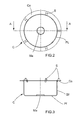
- a container B such as a metal can provided with two parts forming support fasteners, usually called "cabochons" C, arranged on the can B substantially diametrically opposite and located on its face external frontal Ff, cylindrical or substantially cylindrical.
- Such a bottle B is intended for the packaging of a solid content, liquid or pasty, such as industrial products, chemicals, paints, adjuvants ...
- this can have a capacity ranging from 2 liters to 40 liters.
- its diameter may range from about 150 mm to about 350 cm.
- the cabochons C are intended to be associated and to bear the two end parts of a loop A.
- Such a container B comprises a cylindrical or substantially cylindrical metal wall P on which the cabochons C are fixed by welding.
- This wall P is therefore conducting electricity. She is relatively thin.
- Such a container B also has a bottom F.
- Such a container B has an opening O opposite the bottom F and limited by the free edge BI of its cylindrical or substantially cylindrical wall P.
- Such a container B is also provided with a removable cover (not shown).
- the metal wall P has an outer end face Ff which in this case is provided with a non-conductive coating of electricity R, on the side of which are the cabochons C.
- the electrically nonconductive coating R is for example a paint, a lacquer, or a protective and / or decorative layer deposited on the outer face Ff of the container.
- the cabochon C is metal. He is therefore also a conductor of electricity.
- the cabochon C has a front portion Pf having a means of association Ma with one of the two end portions of the handle A.
- This association means is for example a housing or a hole with which a projection or a bead cooperates. terminal of Cove A.
- This cabochon C is chosen so as to also include a peripheral peripheral portion PI of generally cylindrical, flattened, adjacent to the front. On its free edge opposite to the front part, possibly folded to form a transverse annular peripheral flange Co, this cabochon C has pointed peripheral projections S formed by cuts, deformations, corresponding extra thicknesses of this free edge or in any other way similar. Such a cabochon C is rigid and substantially indeformable under normal conditions of use.
- the number of projections S is typically between four and six.
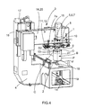
- the welding process for fixing a cabochon C on the outer end face Ff of the metal wall P rests on the implementation of an assembly that may be called a "welding device" 1 and which comprises, so known from the state of the art, first container support means B, such as a table 2 on which a container B is brought to rest therein by its bottom F in order to weld two cabochons C.
- first container support means B such as a table 2 on which a container B is brought to rest therein by its bottom F in order to weld two cabochons C.
- a complete machine 3 includes a frame 4, supply means and container evacuation means B, respectively devoid of cabochons C and provided with cabochons C.
- the welding device 1 also comprises cabochon support means C, functionally associated with cabochon delivery means C.
- the welding device 1 also comprises means 6 for positioning a cabochon C carried by the cabochon support means 5 with respect to and in the vicinity of its final position on the front face Ff of the wall P carried by the table 2 .
- the means 6 for positioning a cabochon C and the cabochon support means 5 C are integrated in an electrode 7 which will be discussed later.
- the electrode 7 comprises magnetic means acting on a cabochon C to maintain it and, if necessary, a housing to position it. If necessary, these means are selectively controlled so that, depending on the time of the process, the maintenance is or is not assured.
- the welding device 1 also comprises welding means 8 including the electrode 7 referred to above, and a counter electrode 9. These are coaxial with respect to a first direction D1. They are also arranged opposite one another.
- the electrode 7 is intended to come against the cabochon C on the side of the outer face of the front part Pf, as well as on the side of the outer end face Ff of the wall P of the container B, while the counter electrode 9, is intended to come against the rear face Fa.
- the welding means 8 also include means 7a for supporting the electrode 7 and means 9a for supporting the counter electrode 9.
- the welding means 8 also include electrical supply means 10 associated with the electrode assembly 7, against the electrode 9.
- the welding means 8 are selectively controlled, so that, depending on the time of the method, the electrode 7 and the counter-electrode 9, respectively the power supply means 10 are made active.
- the welding device 1 also comprises means 11 for relative displacement of the means 7a, 9a for supporting the electrode 7 and the counter electrode 9 suitable for bring closer or, on the contrary, mutually separate the electrode 7 and the counter-electrode 9 in the first direction.
- These means 11 are arranged to allow the electrode 7 and the counter electrode 9 to come against the faces Ff and Fa and to disengage.
- the relative displacement means 11 are themselves also selectively controlled, so that, depending on the moment of the process, they ensure the bringing together or the removal or the maintaining in relative position of the electrode 7 and against -electrode 9.
- the welding device 1 also comprises means 12 able to apply to the electrode 7 and the counter-electrode 9, respectively to their support means 7a, 9a, pressure-antagonistic forces in the first direction D1. These means are themselves also selectively controlled, so that, depending on the time of the process, the pressure is applied or otherwise relaxed.
- the cabochon support means 5 and the means 6 for positioning a cabochon C may be, and in this case are integrated in the electrode 7, or its means 7a, 9a, support.
- the table 2 is placed in the lower position, while the welding means 8 are placed in the upper position, a space 13 being provided between them in which is placed a container B when welding the cabochons C.
- the machine 3 comprises means for orienting the containers B and / or means for orienting the cabochons C, as well as means for adjusting the final position of the cabochons C on the containers B.
- the machine 3 comprises, in a conventional manner, control means, control means, etc.
- the first direction D1 which corresponds to an axis of the welding means 8 is disposed horizontally above the table 2 which defines an axis D2 parallel to a second vertical direction.
- the first direction D1 is found to be substantially orthogonal to the wall P of the container B when a container B is in place on the table 2 and the wall P placed between the electrode 7 and the counter-electrode 9.
- the second direction D2 it is substantially orthogonal to the first direction D1 and substantially parallel to the front face Ff of the wall P of the container B, when it is on the table 2.
- the welding device 1 also comprises means 14 for relative displacement of the means 7a, 9a for supporting the electrode 7 and the counter-electrode 9 - as a whole - and the table 2, for a substantial distance, according to the second direction D2.
- these means 14 are structurally and functionally associated with means 7a, 9a for supporting the electrode 7 and against the electrode 9 either at the table 2 or at both.
- the means 14 are structurally and functionally associated with the means 7a, 9a for supporting the electrode 7 and against the electrode 9 and at the table 2.
- a cross member 15 forming a carriage slidably mounted up and down with respect to a column 16 of the machine 3, a means 17 motor moving up or down in the first direction D1, respectively the keeping in position at a certain height.
- the crosspiece 15 supports the welding device 1.
- the table 2 is also carried by a rod, connecting rod or column 18, guided sliding up and down relative to the frame 4, a means 19 motor ensuring the movement up or down in the first direction D1 respectively holding in position at a certain height.
- the relative displacement means 14 are themselves also selectively controlled, so that, depending on the time of the method, the means 7a, 9a for supporting the electrode 7 and against the electrode 9 and the table 2 are placed relative to each other, according to the second direction D2, in close proximity or in a remote situation or to move from one to the other of these situations.
- the means 7a, 9a for supporting the electrode 7 and the counter-electrode 9 and the table 2 are placed relative to each other, according to the second direction D2, so that the electrode 7 and the counter-electrode 9 can be on either side of the wall P to the final location of the cabochons C of a container B on the table 2.
- the means 7a, 9a for supporting the electrode 7 and the counter-electrode 9 and the table 2 are placed relative to each other, in the second direction D2, so that the electrode 7 and against the electrode 9 are released above the wall P of a container B on the table 2.
- the vertical sliding stroke between the close-up situation and the remote situation is substantial, since it must make it possible to pass the electrode 7 and the counter-electrode 9 from a situation where they are facing the wall P towards the location final cabochons C to a situation where they are completely clear above the container B on the table 2, so as to be able to set up such a container without cabochons C on the table 2 is removed from the table 2 a container B provided with cabochons C.
- the substantial stroke is of the order of 50 to 200 mm.
- the relative displacement means 14 are selectively controlled so that the displacement means 14 are operative while the means 12 capable of applying to the electrode 7 and against the electrode 9 forces are not operative. pressure antagonists, the electrode 7 and the counter-electrode 9 being thus separated from each other.
- the machine 2 comprises two diametrically opposite welding means 8a, 8b with respect to the axis D2 of the table 2. Each of these two welding means 8a, 8b is intended for one of the two cabochons C These two welding means 8a, 8b are coaxial with respect to the first direction D1 and arranged opposite one another.
- the two welding means 8a, 8b are identical and operate in synchronism and analogously. Subsequently, only one of the two will be described.
- the means 7a for supporting the electrode 7 and the means 9a for supporting the counter electrode 9 comprise parts and organs, devices such as guides, carriages, etc. adapted to allow their movement along the first direction D1.
- the means 11 for relative displacement of the means 7a for supporting the electrode 7 and the support means 9a for the counterelectrode 9 comprise members, devices such as motors, pistons, racks, adapted to ensure the bringing movement or, on the contrary, at mutual spacing of the electrode 7 and the counter-electrode 9 in the first direction.
- the means 12 capable of applying to the electrode 7 and to the counter-electrode 9, respectively to their support means 7a, 9a, pressure-antagonistic forces in the first direction D1 may be more or less integrated with the means 11 of displacement in question, for example to be in the form of jacks or the like.
- the electrode 7 is in the form of an elongate cylinder with respect to the direction D1, of relatively small diameter, for example of the order of 2 to 5 centimeters, suitable for being applied on the outer face of the frontal part Pf of the cabochon C and only on it.
- the counter-electrode 9 is in the general form of a ring of axis D2 formed of sections able to be expanded or retracted, such as to be able to come against the rear face Fa of the wall P on a substantial part of its periphery, thus ensuring effective counterpart to the, respectively, the electrode (s) 7.
- the electric current ensuring the welding passes from the electrode 7, to the cabochon C, to the wall P, against the electrode 9.
- the table 2 is electrically insulated.
- the welding device 1 therefore comprises two separate electrodes 7 and a common counter-electrode 9, on the same support means 9a, for welding two cabochons C simultaneously and the like.
- the invention can be extrapolated to a larger number of C-holes and electrodes 7.
- an electrode 7 and a counter-electrode 9 provide the same functions of electrical contact and pressure application.
- the counter-electrode 9 can therefore be described as an electrode, as the electrode 7 could be described as a counter-electrode.
- the welding device 1 also comprises means 20 for relative displacement of the means 7a, 9a for supporting the electrode 7 and the counter electrode 9, as a whole, and the table 2, for a short stroke, according to the second direction D2 whose function will be explained later.
- the means 20 of relative displacement on a short stroke function are arranged so that the pointed projections S of the cabochon placed on a container B, scrape the front face Ff of the wall P of the container B which is exposed to them.
- This scratching is performed under conditions and conditions such that the electrical continuity is ensured between the metal cap C and the metal wall P and that, simultaneously, there is no substantial deformation of the cabochon C.
- the means 14 provide a displacement over a substantial race
- the means 20 provide a movement on a short stroke which, in a typical embodiment, the substantial race is of the order of the or a few millimeters, in any case much smaller than the race means 14.
- the means 20 are structurally and functionally associated with the means 7a, 9a for supporting the electrode 7 and against the electrode 9, either at the table 2 or at both. In addition, they are themselves also selectively controlled so that the displacement occurs at the desired time of the process.
- the relative displacement means 20 over a substantial stroke are structurally common with the means 14 relative displacement on a short stroke. For this reason, it is not necessary to further describe these means 20.
- the means 20 are different from the means 14 by the length of the displacement stroke, as has been indicated, and the moment of displacement in the operating cycle of the welding device 1 and the machine 3.
- the relative movement means 14 is controlled to move them from the remote situation to the close-up situation.
- the electrode 7 and the counter-electrode 9 are placed on either side of the wall P towards the final location of the cabochons C.
- the means 11 for relative displacement of the means 7a, 9a for supporting the electrode 7 and the counter electrode 9 for controlling the electrode 7 and the counterelectrode 9 in the first direction D1 and the electrodes 9 are controlled.
- the pressure applied is sufficient for the pointed projections S of the cabochon C to sink into the coating R, in this case substantially in the first direction D1.
- the pressure applied is sufficient so that the pointed projections S of the cabochon C scrape the front face Ff of the wall P which is exposed to them on a small stroke corresponding to the short race in question.
- the means 12 are able to apply to the electrode 7 and to the counter-electrode 9, respectively to their support means 7a, 9a, pressure-antagonistic forces in the first direction D1, on the other hand the means 20 relative displacement on the short stroke.
- the scratching is performed under conditions and conditions such that the electrical continuity is ensured between the metal cap C and the metal wall P and that, simultaneously, there is no substantial deformation of the cabochon C.
- the cabochon C is welded to the front face Ff of the wall P by the welding means 8, and more particularly the electrical supply means 10 are controlled for this purpose.
- the electrode 7 and the counter-electrode 9 of the cabochon C and the wall P on which the cabochon C is soldered are moved apart, and released, and the counter-electrode 9 is retracted.
- the diameter had been increased to come against the rear face Fa of the wall P, to allow its subsequent exit of the container B through the opening O.
- the means 12 are controlled to stop applying to the electrode 7 and the counter-electrode 9, respectively to their support means 7a, 9a, pressure antagonistic forces in the first direction D1 and control means 11 relative displacement means 7a, 9a of support of the electrode 7 and against the electrode 9 to move the electrode 7 away from the counterelectrode 9 in the first direction D1.
- the container B having the two welded C-hooks C of the electrode 7 and the counter-electrode 9 is then released.
- the relative displacement of the cabochon C with respect to the container B is ensured over a stroke at least equal to that allowing the pointed projections S of the cabochon C to stop being applied to the coating R in order to be in contact with the metal wall P and ensure electrical continuity. And, more precisely, on a substantially equal course to that which just allows the pointed projections of the cabochon to stop being applied to the coating in order to be in contact with the metal wall and to ensure electrical continuity. Indeed, it is not necessary that the relative displacement travel of the cabochon C relative to the container B is greater than that allows the electrical continuity.
- the invention also relates to the method of placing on the container B a loop A as indicated above, in which, to the process of welding the cabochons as just described, a step of combining the two end portions of said handle A to both said cabochons C.
Applications Claiming Priority (1)
| Application Number | Priority Date | Filing Date | Title |
|---|---|---|---|
| FR0854364A FR2933017B1 (fr) | 2008-06-27 | 2008-06-27 | Soudage de cabochons metalliques sur une paroi metallique ayant un revetement non conducteur de l'electricite |
Publications (1)
| Publication Number | Publication Date |
|---|---|
| EP2138261A1 true EP2138261A1 (de) | 2009-12-30 |
Family
ID=40352026
Family Applications (1)
| Application Number | Title | Priority Date | Filing Date |
|---|---|---|---|
| EP09305495A Withdrawn EP2138261A1 (de) | 2008-06-27 | 2009-05-29 | Schweissen von Haltestücken für einen Griffbückel auf eine mit einem nicht-leitendem Material beschichteten Wandung |
Country Status (2)
| Country | Link |
|---|---|
| EP (1) | EP2138261A1 (de) |
| FR (1) | FR2933017B1 (de) |
Cited By (2)
| Publication number | Priority date | Publication date | Assignee | Title |
|---|---|---|---|---|
| CN104526146A (zh) * | 2014-12-30 | 2015-04-22 | 苏州东鸿瑞包装科技有限公司 | 单头点焊机 |
| CN109014530A (zh) * | 2017-01-03 | 2018-12-18 | 东莞理工学院 | 一种对接碰焊机的金属丝送料机构 |
Families Citing this family (2)
| Publication number | Priority date | Publication date | Assignee | Title |
|---|---|---|---|---|
| CN102969640B (zh) * | 2013-01-06 | 2014-12-17 | 东莞市精研自动化机械有限公司 | 一种全自动电容电阻焊接机 |
| CN106583902B (zh) * | 2017-01-19 | 2022-04-01 | 广州松兴电气股份有限公司 | 一种凸焊螺母加压臂装置 |
Citations (8)
| Publication number | Priority date | Publication date | Assignee | Title |
|---|---|---|---|---|
| US2845522A (en) | 1956-05-25 | 1958-07-29 | Edward C Hall | Method of projection welding of handle or bail ears or lugs upon receptacles |
| US3233073A (en) * | 1962-02-05 | 1966-02-01 | Ruetschi Charles | Projection-welding method for insulation-coated surfaces |
| US3233072A (en) | 1962-03-15 | 1966-02-01 | Grotnes Machine Works Inc | Welding machine and procedure |
| US3340379A (en) | 1963-09-24 | 1967-09-05 | Chicago United Products Compan | Method of welding button through paint |
| US3476905A (en) | 1966-06-16 | 1969-11-04 | Bent Werdelin Larsen | Welding of mountings on hollow sheet-metal bodies |
| US3476289A (en) | 1968-06-28 | 1969-11-04 | Carando Machine Works | Bail-attachment ear for metallic containers |
| US3975611A (en) * | 1969-12-01 | 1976-08-17 | Trw Inc. | Trim fastening |
| EP1378312A2 (de) * | 2002-07-04 | 2004-01-07 | Newfrey LLC | Verfahren und Vorrichtung zum Lichtbogenschweissen von Elementen auf beschichtete Bauteile und Element geeignet für das Lichtbogenschweissverfahren |
-
2008
- 2008-06-27 FR FR0854364A patent/FR2933017B1/fr active Active
-
2009
- 2009-05-29 EP EP09305495A patent/EP2138261A1/de not_active Withdrawn
Patent Citations (8)
| Publication number | Priority date | Publication date | Assignee | Title |
|---|---|---|---|---|
| US2845522A (en) | 1956-05-25 | 1958-07-29 | Edward C Hall | Method of projection welding of handle or bail ears or lugs upon receptacles |
| US3233073A (en) * | 1962-02-05 | 1966-02-01 | Ruetschi Charles | Projection-welding method for insulation-coated surfaces |
| US3233072A (en) | 1962-03-15 | 1966-02-01 | Grotnes Machine Works Inc | Welding machine and procedure |
| US3340379A (en) | 1963-09-24 | 1967-09-05 | Chicago United Products Compan | Method of welding button through paint |
| US3476905A (en) | 1966-06-16 | 1969-11-04 | Bent Werdelin Larsen | Welding of mountings on hollow sheet-metal bodies |
| US3476289A (en) | 1968-06-28 | 1969-11-04 | Carando Machine Works | Bail-attachment ear for metallic containers |
| US3975611A (en) * | 1969-12-01 | 1976-08-17 | Trw Inc. | Trim fastening |
| EP1378312A2 (de) * | 2002-07-04 | 2004-01-07 | Newfrey LLC | Verfahren und Vorrichtung zum Lichtbogenschweissen von Elementen auf beschichtete Bauteile und Element geeignet für das Lichtbogenschweissverfahren |
Cited By (2)
| Publication number | Priority date | Publication date | Assignee | Title |
|---|---|---|---|---|
| CN104526146A (zh) * | 2014-12-30 | 2015-04-22 | 苏州东鸿瑞包装科技有限公司 | 单头点焊机 |
| CN109014530A (zh) * | 2017-01-03 | 2018-12-18 | 东莞理工学院 | 一种对接碰焊机的金属丝送料机构 |
Also Published As
| Publication number | Publication date |
|---|---|
| FR2933017A1 (fr) | 2010-01-01 |
| FR2933017B1 (fr) | 2011-03-04 |
Similar Documents
| Publication | Publication Date | Title |
|---|---|---|
| EP1768911B1 (de) | Behälterbehandlungsmaschine mit gesteuerten greifmitteln zum ergreifen von behältern am hals | |
| EP2138261A1 (de) | Schweissen von Haltestücken für einen Griffbückel auf eine mit einem nicht-leitendem Material beschichteten Wandung | |
| EP2509738B1 (de) | Vorrichtung zum austausch einer elektrode mit verbesserter sichereit | |
| CA1074070A (fr) | Apparreillage de pose de troncons de gaine thermoplastique autour de recipients | |
| EP3843928B1 (de) | Werkzeug zum bearbeiten von girlanden und befestigungslöchern eines scheibenflansches mittels pecm und verfahren mit diesem werkzeug | |
| EP0524121A1 (de) | Einrichtung zum Entmanteln der mit einem isolierendem oder schutzendem Schicht überzogener Leiteroberfläche | |
| EP2429798B1 (de) | Verfahren und vorrichtung zum warmfomen und verzieren von behältern | |
| EP0867253B1 (de) | Verfahren und Anlage zum Be- und Entladen von Elektroden einer Punktschweisszange bei einem Widerstandspunktschweissgerät | |
| EP2931454B1 (de) | Montageverfahren mit magnetischem bördeln | |
| EP0778103B1 (de) | Verfahren und Vorrichtung zum serienweise elektrochemischen Ätzen von Werstücken | |
| EP0500410A1 (de) | Punktschweisszange | |
| FR3065384A1 (fr) | Barillet d'alimentation d'embouts de pince de soudage | |
| FR2658587A1 (fr) | Installation pour la manutention de chapeaux de bouteilles a gaz, avant et apres le remplissage de ces bouteilles. | |
| WO2014006304A1 (fr) | Outil de frettage de pièces mécaniques et procédé de frettage utilisant un tel outil | |
| FR2525524A1 (fr) | Appareillage et procede de soudage par friction | |
| EP3626426B1 (de) | Verbindungssystem zum verbinden zweier vorrichtungen mit einer fluidverbindung zwischen den beiden vorrichtungen | |
| FR3069589A1 (fr) | Procede d'insertion d'un organe d'assemblage dans une piece d'aeronef | |
| FR3084658A1 (fr) | Procede d'extraction d'une bobine pleine et son dispositif | |
| EP0908293B1 (de) | Verfahren zum Verbinden eines festen Kunststoffteiles mit einem flexiblen Film auf eine Walze | |
| FR2845938A1 (fr) | Procede pour l'extraction et/ou le changement des electrodes d'une pince a souder ou d'un appareil de soudage | |
| EP2226132B1 (de) | Vorrichtung zum Umformen des Randes eines metallischen Behälters | |
| FR2702738A1 (fr) | Procédé et machine pour la fabrication de poches en matière plastique destinées à servir d'emballages étanches souples pour des produits pâteux. | |
| WO2024100121A1 (fr) | Dispositif pneumatique de couplage automatique d'outil pour une machine d'impression tridimensionnelle a changement d'outils | |
| EP3967464A1 (de) | Brotschneidemaschine mit einem abnehmbaren deckel | |
| EP1576629B1 (de) | Vorrichtung zur herstellung einer speichereinheit für elektrische energie enthaltend eine verbesserte wickelhülse |
Legal Events
| Date | Code | Title | Description |
|---|---|---|---|
| PUAI | Public reference made under article 153(3) epc to a published international application that has entered the european phase |
Free format text: ORIGINAL CODE: 0009012 |
|
| AK | Designated contracting states |
Kind code of ref document: A1 Designated state(s): AT BE BG CH CY CZ DE DK EE ES FI FR GB GR HR HU IE IS IT LI LT LU LV MC MK MT NL NO PL PT RO SE SI SK TR |
|
| 17P | Request for examination filed |
Effective date: 20100616 |
|
| 17Q | First examination report despatched |
Effective date: 20100714 |
|
| STAA | Information on the status of an ep patent application or granted ep patent |
Free format text: STATUS: THE APPLICATION IS DEEMED TO BE WITHDRAWN |
|
| 18D | Application deemed to be withdrawn |
Effective date: 20140220 |