EP2138138B1 - Vorrichtung zum Ausbilden gekrümmter Schnittflächen in einem transparenten Material - Google Patents
Vorrichtung zum Ausbilden gekrümmter Schnittflächen in einem transparenten Material Download PDFInfo
- Publication number
- EP2138138B1 EP2138138B1 EP09172932.7A EP09172932A EP2138138B1 EP 2138138 B1 EP2138138 B1 EP 2138138B1 EP 09172932 A EP09172932 A EP 09172932A EP 2138138 B1 EP2138138 B1 EP 2138138B1
- Authority
- EP
- European Patent Office
- Prior art keywords
- cornea
- eye
- curvature
- control unit
- cut surface
- Prior art date
- Legal status (The legal status is an assumption and is not a legal conclusion. Google has not performed a legal analysis and makes no representation as to the accuracy of the status listed.)
- Expired - Lifetime
Links
Images


Classifications
-
- A—HUMAN NECESSITIES
- A61—MEDICAL OR VETERINARY SCIENCE; HYGIENE
- A61F—FILTERS IMPLANTABLE INTO BLOOD VESSELS; PROSTHESES; DEVICES PROVIDING PATENCY TO, OR PREVENTING COLLAPSING OF, TUBULAR STRUCTURES OF THE BODY, e.g. STENTS; ORTHOPAEDIC, NURSING OR CONTRACEPTIVE DEVICES; FOMENTATION; TREATMENT OR PROTECTION OF EYES OR EARS; BANDAGES, DRESSINGS OR ABSORBENT PADS; FIRST-AID KITS
- A61F9/00—Methods or devices for treatment of the eyes; Devices for putting in contact-lenses; Devices to correct squinting; Apparatus to guide the blind; Protective devices for the eyes, carried on the body or in the hand
- A61F9/007—Methods or devices for eye surgery
- A61F9/008—Methods or devices for eye surgery using laser
-
- A—HUMAN NECESSITIES
- A61—MEDICAL OR VETERINARY SCIENCE; HYGIENE
- A61F—FILTERS IMPLANTABLE INTO BLOOD VESSELS; PROSTHESES; DEVICES PROVIDING PATENCY TO, OR PREVENTING COLLAPSING OF, TUBULAR STRUCTURES OF THE BODY, e.g. STENTS; ORTHOPAEDIC, NURSING OR CONTRACEPTIVE DEVICES; FOMENTATION; TREATMENT OR PROTECTION OF EYES OR EARS; BANDAGES, DRESSINGS OR ABSORBENT PADS; FIRST-AID KITS
- A61F9/00—Methods or devices for treatment of the eyes; Devices for putting in contact-lenses; Devices to correct squinting; Apparatus to guide the blind; Protective devices for the eyes, carried on the body or in the hand
- A61F9/007—Methods or devices for eye surgery
- A61F9/008—Methods or devices for eye surgery using laser
- A61F9/00825—Methods or devices for eye surgery using laser for photodisruption
- A61F9/00827—Refractive correction, e.g. lenticle
- A61F9/00829—Correction of higher orders
-
- A—HUMAN NECESSITIES
- A61—MEDICAL OR VETERINARY SCIENCE; HYGIENE
- A61F—FILTERS IMPLANTABLE INTO BLOOD VESSELS; PROSTHESES; DEVICES PROVIDING PATENCY TO, OR PREVENTING COLLAPSING OF, TUBULAR STRUCTURES OF THE BODY, e.g. STENTS; ORTHOPAEDIC, NURSING OR CONTRACEPTIVE DEVICES; FOMENTATION; TREATMENT OR PROTECTION OF EYES OR EARS; BANDAGES, DRESSINGS OR ABSORBENT PADS; FIRST-AID KITS
- A61F9/00—Methods or devices for treatment of the eyes; Devices for putting in contact-lenses; Devices to correct squinting; Apparatus to guide the blind; Protective devices for the eyes, carried on the body or in the hand
- A61F9/007—Methods or devices for eye surgery
- A61F9/008—Methods or devices for eye surgery using laser
- A61F2009/00861—Methods or devices for eye surgery using laser adapted for treatment at a particular location
- A61F2009/00872—Cornea
-
- A—HUMAN NECESSITIES
- A61—MEDICAL OR VETERINARY SCIENCE; HYGIENE
- A61F—FILTERS IMPLANTABLE INTO BLOOD VESSELS; PROSTHESES; DEVICES PROVIDING PATENCY TO, OR PREVENTING COLLAPSING OF, TUBULAR STRUCTURES OF THE BODY, e.g. STENTS; ORTHOPAEDIC, NURSING OR CONTRACEPTIVE DEVICES; FOMENTATION; TREATMENT OR PROTECTION OF EYES OR EARS; BANDAGES, DRESSINGS OR ABSORBENT PADS; FIRST-AID KITS
- A61F9/00—Methods or devices for treatment of the eyes; Devices for putting in contact-lenses; Devices to correct squinting; Apparatus to guide the blind; Protective devices for the eyes, carried on the body or in the hand
- A61F9/007—Methods or devices for eye surgery
- A61F9/008—Methods or devices for eye surgery using laser
- A61F2009/00897—Scanning mechanisms or algorithms
-
- A—HUMAN NECESSITIES
- A61—MEDICAL OR VETERINARY SCIENCE; HYGIENE
- A61F—FILTERS IMPLANTABLE INTO BLOOD VESSELS; PROSTHESES; DEVICES PROVIDING PATENCY TO, OR PREVENTING COLLAPSING OF, TUBULAR STRUCTURES OF THE BODY, e.g. STENTS; ORTHOPAEDIC, NURSING OR CONTRACEPTIVE DEVICES; FOMENTATION; TREATMENT OR PROTECTION OF EYES OR EARS; BANDAGES, DRESSINGS OR ABSORBENT PADS; FIRST-AID KITS
- A61F9/00—Methods or devices for treatment of the eyes; Devices for putting in contact-lenses; Devices to correct squinting; Apparatus to guide the blind; Protective devices for the eyes, carried on the body or in the hand
- A61F9/007—Methods or devices for eye surgery
- A61F9/008—Methods or devices for eye surgery using laser
- A61F9/009—Auxiliary devices making contact with the eyeball and coupling in laser light, e.g. goniolenses
Definitions
- the invention relates to a device for forming curved cut surfaces in a transparent material, in particular in the cornea, with a laser radiation source, which focuses laser radiation into the material and causes optical breakthroughs there, wherein a scanning device, which adjusts the focal point three-dimensionally, and a control device are provided, which controls the scanning device to form the cutting surface by juxtaposing the optical openings in the material, and wherein the scanning device for adjusting the focal point in a spatial direction has an adjustable optics.
- Curved cut surfaces within a transparent material are generated in particular in laser surgical procedures and there especially in ophthalmological surgery. Treatment laser radiation within the tissue, ie below the tissue surface, is focused in such a way that optical breakthroughs occur in the tissue.
- the two-dimensional deflection of the laser radiation is like the focus adjustment equally for the accuracy with which the cut surface can be generated, decisive.
- the adjustment speed which can be achieved, has an effect on the speed with which the required cutting surface can be produced.
- Rapid cutting surface production is not only desirable for comfort or time-saving desires, against the background that inevitably movements of the eye occur in ophthalmological operations, rapid cutting surface production additionally promotes the optical quality of the result obtained or reduces the requirements for any tracking of eye movements.
- the US 5993438 describes a cut surface generation with focus point guidance along a circular spiral.
- the WO 94/09849 as well as the US 6325792 disclose elliptical ablation for correction of ametropia.
- the invention is therefore the object of a device of the type mentioned in such a way that for the production of a cutting surface the shortest possible time is required.
- contour lines of the cut surface to be produced are related to that spatial direction of the system in which the slowest adjustment speed is given. It is thereby possible to leave the focus in this spatial direction almost unchanged over a longer period of time, and the higher adjustment speed in the other two spatial directions can be exploited without limitation. Overall, a fast cut surface generation is obtained.
- the contour lines can be conveniently obtained by cutting the curved section surface with plane perpendicular to the first spatial direction. The more precisely the planes of the contour lines are perpendicular to the first spatial direction, the more constant the adjustment can be maintained in the first spatial direction during a contour line.
- the laser radiation is adjusted at least with respect to the two spatial directions that are perpendicular to the plane of the contour line, taking into account the contour line. It is on the one hand possible that the focal point within certain tolerances exactly follows the respective contour line. In this case, the focal point describes concentrically located closed trajectories, wherein for each trajectory of the focus in the first spatial direction is set accordingly different. Instead of closed trajectories that follow the contour lines exactly within certain tolerances, it is also possible to connect the contour lines together. The focal point is thereby moved along a contour line, wherein the individual contour lines are not executed as closed trajectories, but adjacent contour lines are connected by a sliding transition, so that the total focus point is moved on a single continuous trajectory.
- This continuous juxtaposition of contour lines can preferably be achieved in that the focal point is moved in each case to a residual piece completely along the contour line and in the remaining piece by adjustment of the focal point in the first spatial direction, a transition to the next contour line is effected.
- This approach has the advantage that the requirements for the adjustment in the first spatial direction are lowered again, as well as during the transition between two contour lines optical breakthroughs are generated to form the cut surface.
- the contour line image will depend on the topography, ie the curvature of the cut surface. In a spherically curved cut surface concentric circular contour lines are obtained.
- a spherically curved cut surface will be the exception rather than an ellipsoid or toroidal surface.
- the contour lines are designed according to the invention as (advantageously concentric) ellipses.
- the ellipticity is between 1.0 and 1.1 or even 1.2.
- the contour lines are also based on the guidance of the focal point in such a way that the deflected focus point follows an ellipsoid spiral, ie a spiral lying on the lateral surface of the curved sectional surface.
- the ellipticity of the ellipses or the ellipsoid spiral may depend on the shape of the corneal surface. Ellipticity means the ratio of the major axis of an ellipse to its minor axis.
- the natural surface topography is used.
- the shape of this contact glass plays a role.
- the approach using a contact glass since the topography with pressed contact glass is well defined.
- a flat contact glass represents a mathematical borderline case, and the concept of the contour line scan leads to degeneration here the trajectories, although these can still be described as closed.
- a dependence of the surface topography eg. B. the ellipticity of the curvature of the contact glass. This is true even if the curvature is purely spherical, since then also sets an ellipsoidal shape for the cut surface. However, the ellipticity is usually not the same in the entire edit field, but often shows a radial dependence.
- e z R a 2 - R a - z 2 R b 2 - R b - z 2 .
- R a and R b denote the radii of curvature of the cornea surface in the direction of the major axes of the ellipse
- the ellipticity of the trajectories is usually less than 1.4 (major axis 10% longer than the minor major axis) for a contact lens having a radius of curvature approximately equal to that of the human eye.
- the ellipticity of a sphero-cylindrical correction of -2dpt and 1dpt is only about 1.03 in the central field near the optical axis and increases by about 10% with the distance from the optical axis to the outer trajectory.
- the variability of the ellipticity or a corresponding modification of an ideal circular path does not play a disturbing role in the correction of higher-order aberrations, and thus can be assumed to be constant in a first approximation.
- the distances between the control lines underlying the contour lines are naturally given by the distances of the planes, which are generated by a mathematical section with the curved section of the contour lines.
- the distances in the first spatial direction are chosen so that the average distances of the contour lines are constant and in particular below a threshold, which is of course less than the aforementioned limit.
- a threshold which is of course less than the aforementioned limit.
- the distance between adjacent contour lines on the long semiaxis can be evaluated in a simplified manner in the contour line image to ensure that the optical breakthroughs are sufficiently dense.
- the curved cut surface required for this purpose also has higher orders of curvature. If you want to represent these shapes directly by contour lines, sometimes results in a very complex contour line image, which requires a complex and fast adjustment in the two other spatial directions when descending a contour line. For such cases, it is expedient to neglect the higher curvature orders of the curved cut surface in the determination of the contour lines and then, while the focus point is adjusted in the other two spatial directions according to the contour line, the adjustment in the first spatial direction according to the influence of the higher curvature orders change.
- the Correction of higher aberrations is then then modulated in the first spatial direction, for example in the z-direction, to a basic movement which corresponds to the curved sectional area without higher aberrations.
- the adjustment of the focal point can be effected with a scanning device which, for adjustment in the first spatial direction (usually the z-direction), has a zoom lens preferably designed as a tunable telescope and for the other two spatial directions (usually x and y). Directions) has two tilting mirrors with crossed axes of rotation.
- a scanning device which, for adjustment in the first spatial direction (usually the z-direction), has a zoom lens preferably designed as a tunable telescope and for the other two spatial directions (usually x and y). Directions) has two tilting mirrors with crossed axes of rotation.
- the surface of the material in particular the cornea front surface, has a known shape. This facilitates the guidance of the focal point.
- a contact glass is advantageous both for the method described and for the device according to the invention.
- the shape imparted by the contact glass to the surface of the material is known in the control means or is suitably input so that the control means bases the choice of contour lines on the surface shape of the material.
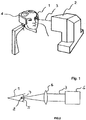
- FIG. 1 a laser surgical instrument for treating an eye 1 of a patient is shown, wherein the laser surgical instrument 2 is used to perform a refractive correction.
- the instrument 2 dispenses a treatment laser beam 3 onto the eye of the patient 1, whose head is fixed in a head holder 4.
- the laser surgical instrument 2 is capable of generating a pulsed laser beam 3, so that the in US 6,110,166 described method can be performed.
- the laser surgical instrument 2 has, as in FIG. 2 is shown schematically, a beam source S, whose radiation is focused in the cornea 5 of the eye 1. Defective vision of the patient's eye 1 is remedied by means of the laser surgical instrument 2 by removing material from the cornea 5 in such a way that the refractive properties of the cornea change by a desired amount. The material is taken from the stroma of the cornea, which lies below the epithelium and Bowman's membrane above the Decemet's membrane and the endothelium.
- Material removal takes place by separating tissue layers in the cornea by focusing the high-energy pulsed laser beam 3 by means of an objective telescope 6 in a focus 7 in the cornea 5.
- Each pulse of the pulsed laser radiation 3 generates an optical breakthrough in the tissue, which initiates a plasma bubble 8.
- the tissue layer separation comprises a larger area than the focus 7 of the laser radiation 3.
- many plasma bubbles 8 are now lined up during the treatment.
- the adjoining plasma bubbles 8 then form a cut surface 9 which circumscribes a partial volume T of the stroma, namely the material of the cornea 5 to be removed.
- the laser-surgical instrument 2 acts through the laser radiation 3 like a surgical knife, which, without violating the surface of the cornea 5, directly separates material layers in the interior of the cornea 5. If the cut is carried out by further generation of plasma bubbles 8 as far as the surface of the cornea 5, a material of the cornea 5 isolated by the cut surface 9 can be pulled out laterally and thus removed.
- FIG. 3 The production of the cutting surface 9 by means of the laser surgical instrument 2 is in FIG. 3 shown schematically.
- the cut surface 9 is formed.
- the focus shift takes place on the one hand in one embodiment by means of in FIG. 4 schematically shown deflection unit 10, which deflects the incident on a main axis of incidence H on the eye 1 laser beam 3 about two mutually perpendicular axes.
- the deflection unit 10 uses a line mirror 11 and a picture mirror 12 for this, which leads to two consecutive spatial deflection axes. The crossing point of the main beam axis with the deflection axis is then the respective deflection point.
- the telescope 6 is suitably adjusted. This allows the focus 7 in the in FIG. 4 schematically shown x / y / z coordinate system along three orthogonal axes are adjusted.
- the deflection unit 10 adjusts the focus in the x / y plane, whereby the line mirror allows to adjust the focus in the x-direction and the image mirror in the y-direction.
- the telescope 6 acts on the z-coordinate of the focus 7.
- the partial volume T is also correspondingly curved.
- the corneal curvature thus has the effect of a field curvature. This is taken into account by suitable control of the deflection unit.
- a contour line image 16 is determined from the curvature thereof, as shown by way of example in FIG. 5 is shown in the x / y plane.
- the contour line image 16 consists of a multiplicity of concentric contour lines 17 which connect points of the same z coordinates to the section 9.
- the contour line image 16 was obtained, in which from the curved sectional surface 9 determines those points, for. B. were filtered out, which have at least approximately a certain z-coordinate. This corresponds to a mathematical section of the curved section 9 with an x / y plane with the respective z-coordinate.
- the z coordinates were used to generate the individual contour lines 17 of the contour line image 16 of FIG. 5 chosen so that the distances adjacent the contour lines 17 in the contour line image 16 do not exceed a predetermined limit. This limit value is defined by the maximum permissible distance between two plasma bubbles 8, which is permissible for achieving a continuous sectional area.
- the focus 7 is adjusted by the deflection unit 10 in accordance with the contour lines 17, the zoom lens 6 setting the corresponding z coordinate for the focus 7 for each contour line 17. While the focus 7 runs over a contour line 17, the telescope 6 remains fixed. Only during in FIG. 5 dashed lines transitions 18 between adjacent contour lines is an adjustment.
- FIG. 6 shows a section of the contour line image 16.
- Each contour line 17 is traversed as almost completely closed curve of the focus 7, wherein the distance between the beginning and end of a contour line 17 does not exceed the limit defined by the maximum allowable distance between two plasma bubbles 8.
- a transition 18 by adjusting the telescope 6 for each next contour line.
- Between the contour lines 17.1 and 17.2 is thereby a transition 18.1, between the contour lines 17.2 and 17.3 a transition 18.2. This continues for all contour lines.
- the contour lines 17 can be written as a continuous track.
- FIG. 6 are the transitions 18 substantially on fall lines of the curved section surface.
- FIG. 7 shows in this regard other transitions 18.1 to 18.3, in which there is a sliding transition between the end of a contour line and the beginning of the immediately adjacent contour line. To clarify is not followed by the focus 7 continuation of the corresponding contour lines in FIG. 7 dashed lines. As can be seen, at the end of a contour line 17, a sliding transition to the next contour line is made by suitable control of the line mirror 11 and the image mirror 12. At the same time, the telescope 6 is adjusted synchronously during the transitions 18.1, 18.2 and 18.3 reached thereby.
- FIG. 8a shows another example of a contour line image 16, which is constructed here of concentric elliptic contour lines 17.
- the beam source S controlled so that it produces no optical breakthrough in the material 5, ie no plasma bubble 8. This is in FIG. 9 represented by different hatchings.
- the beam source S can generate plasma bubbles 8.
- the beam source S is switched off or at least operated so that no plasma bubbles 8 can arise.
- FIG. 10 The structure present in such a procedure is shown schematically in FIG. 10 shown, which is essentially the FIG. 2 corresponds, so that on there already described elements will not be discussed further.
- a contact glass 21 is now placed on the cornea 5, which gives with its inner surface 22 of the front surface of the cornea 5 a certain profile.
- the procedure described so far is now in the determination of the trajectories, z. As the contour lines, no longer the curvature of the cornea 5 in the free, ie natural state, based, but the predetermined by the inner surface 22 of the contact glass 21 shape.
- the cornea 5 is approximately spherically curved with respect to the eye center Z, so that it is clearly position-determined by a radius of curvature R Cv and the position of the center Z on the optical axis OA.
- the coordinates of a point at which a laser focus 7 comes to lie to produce a plasma bubble 8 are thus either in cylindrical coordinates (radius r of the optical axis OA, distance z from the vertex plane and angle ⁇ ) or in radial coordinates (radius r from the eye center Z, angle ⁇ and ⁇ ) can be clearly stated.
- the contour lines or the trajectories on which the focus 7 is adjusted can be calculated and specified, wherein in cylindrical coordinates elliptical trajectories can be described particularly simply mathematically.
- FIG. 13 If one then places a contact glass 21 on the eye, they lie in FIG. 13 shown conditions, as long as the contact glass 21 with its inner surface 22 does not deform the cornea.
- the contact glass is spherically curved here, the radius of curvature R G being greater than the radius of curvature R Cv of the cornea.
- the contact glass 21 is pressed onto the eye 1, the cornea 5 deforms from a sphere to an ellipsoid; it is the in FIG. 12 shown schematically a.
- the pressing thus causes the deformation of the eye, which applies at least in a region around the optical axis OA much closer to the inner surface 22 of the contact glass 21, as without contact pressure.
- the ellipticity of the trajectories depends on the shape of this contact glass.
- Ellipticity means the ratio of the major axis of an ellipse to its minor axis.
- a plane contact glass is a mathematical borderline case, and the concept of the contour scan leads to the degeneration of the trajectories, although these can still be described as closed.
- a dependence of the ellipticity on the curvature of the contact glass results.
- the ellipticity is usually not the same in the entire processing field, but shows a radial dependence.
- e z R a 2 - R a - z 2 R b 2 - R b - z 2 .
- the ellipticity of the trajectories is typically less than 1.2 for a contact lens having a radius of curvature approximately equal to that of the human eye (major axis being 10% longer than the minor major axis).
- the ellipticity of a sphero-cylindrical correction of -2dpt and 1dpt is only about 1.03 in the central field near the optical axis and increases by about 10% with the distance from the optical axis to the outer trajectory.
- the variability of the ellipticity or a corresponding modification of an ideal circular path does not play a disturbing role in the correction of higher-order aberrations, and can thus be assumed to be constant in a first approximation.
- the surface topography can be determined by suitable methods and devices and is then taken into account in the process (analogously) as well as the topography determined by the pressing process.
- the shape of the contact glass surface can not be described by one sphere, but follows another surface function, for example a paraboloid, a transformation law can be given analogously to the transformation given above, but following the same physical idea.
Landscapes
- Health & Medical Sciences (AREA)
- Ophthalmology & Optometry (AREA)
- Life Sciences & Earth Sciences (AREA)
- Animal Behavior & Ethology (AREA)
- Optics & Photonics (AREA)
- Surgery (AREA)
- Engineering & Computer Science (AREA)
- Biomedical Technology (AREA)
- Heart & Thoracic Surgery (AREA)
- Vascular Medicine (AREA)
- Physics & Mathematics (AREA)
- Nuclear Medicine, Radiotherapy & Molecular Imaging (AREA)
- General Health & Medical Sciences (AREA)
- Public Health (AREA)
- Veterinary Medicine (AREA)
- Laser Surgery Devices (AREA)
- Eyeglasses (AREA)
- Vehicle Interior And Exterior Ornaments, Soundproofing, And Insulation (AREA)
- Shaping Of Tube Ends By Bending Or Straightening (AREA)
- Knives (AREA)
Priority Applications (4)
| Application Number | Priority Date | Filing Date | Title |
|---|---|---|---|
| EP19175592.5A EP3545920B1 (de) | 2003-07-25 | 2004-07-23 | Vorrichtung zum ausbilden gekrümmter schnittflächen in einem transparenten material |
| PL10182173T PL2260805T3 (pl) | 2003-07-25 | 2004-07-23 | Urządzenie i sposób tworzenia zakrzywionych powierzchni cięcia w rogówce |
| EP10182173.4A EP2260805B1 (de) | 2003-07-25 | 2004-07-23 | Vorrichtung und Verfahren zum Ausbilden gekrümmter Schnittflächen in der Augenhornhaut |
| PL09172932T PL2138138T4 (pl) | 2003-07-25 | 2004-07-23 | Urządzenie do utworzenia zakrzywionych powierzchni cięcia w przezroczystym materiale |
Applications Claiming Priority (2)
| Application Number | Priority Date | Filing Date | Title |
|---|---|---|---|
| DE10334110A DE10334110A1 (de) | 2003-07-25 | 2003-07-25 | Vorrichtung und Verfahren zum Ausbilden gekrümmter Schnittflächen in einem transparenten Material |
| EP04763451A EP1648360B1 (de) | 2003-07-25 | 2004-07-23 | Vorrichtung zum ausbilden gekrümmter schnittflächen in einem transparenten material |
Related Parent Applications (2)
| Application Number | Title | Priority Date | Filing Date |
|---|---|---|---|
| EP04763451A Division EP1648360B1 (de) | 2003-07-25 | 2004-07-23 | Vorrichtung zum ausbilden gekrümmter schnittflächen in einem transparenten material |
| EP04763451.4 Division | 2004-07-23 |
Related Child Applications (4)
| Application Number | Title | Priority Date | Filing Date |
|---|---|---|---|
| EP19175592.5A Division EP3545920B1 (de) | 2003-07-25 | 2004-07-23 | Vorrichtung zum ausbilden gekrümmter schnittflächen in einem transparenten material |
| EP10182173.4A Division EP2260805B1 (de) | 2003-07-25 | 2004-07-23 | Vorrichtung und Verfahren zum Ausbilden gekrümmter Schnittflächen in der Augenhornhaut |
| EP10182173.4A Division-Into EP2260805B1 (de) | 2003-07-25 | 2004-07-23 | Vorrichtung und Verfahren zum Ausbilden gekrümmter Schnittflächen in der Augenhornhaut |
| EP10182173.4 Division-Into | 2010-09-29 |
Publications (3)
| Publication Number | Publication Date |
|---|---|
| EP2138138A2 EP2138138A2 (de) | 2009-12-30 |
| EP2138138A3 EP2138138A3 (de) | 2012-02-22 |
| EP2138138B1 true EP2138138B1 (de) | 2017-10-25 |
Family
ID=34071920
Family Applications (4)
| Application Number | Title | Priority Date | Filing Date |
|---|---|---|---|
| EP09172932.7A Expired - Lifetime EP2138138B1 (de) | 2003-07-25 | 2004-07-23 | Vorrichtung zum Ausbilden gekrümmter Schnittflächen in einem transparenten Material |
| EP10182173.4A Expired - Lifetime EP2260805B1 (de) | 2003-07-25 | 2004-07-23 | Vorrichtung und Verfahren zum Ausbilden gekrümmter Schnittflächen in der Augenhornhaut |
| EP19175592.5A Expired - Lifetime EP3545920B1 (de) | 2003-07-25 | 2004-07-23 | Vorrichtung zum ausbilden gekrümmter schnittflächen in einem transparenten material |
| EP04763451A Expired - Lifetime EP1648360B1 (de) | 2003-07-25 | 2004-07-23 | Vorrichtung zum ausbilden gekrümmter schnittflächen in einem transparenten material |
Family Applications After (3)
| Application Number | Title | Priority Date | Filing Date |
|---|---|---|---|
| EP10182173.4A Expired - Lifetime EP2260805B1 (de) | 2003-07-25 | 2004-07-23 | Vorrichtung und Verfahren zum Ausbilden gekrümmter Schnittflächen in der Augenhornhaut |
| EP19175592.5A Expired - Lifetime EP3545920B1 (de) | 2003-07-25 | 2004-07-23 | Vorrichtung zum ausbilden gekrümmter schnittflächen in einem transparenten material |
| EP04763451A Expired - Lifetime EP1648360B1 (de) | 2003-07-25 | 2004-07-23 | Vorrichtung zum ausbilden gekrümmter schnittflächen in einem transparenten material |
Country Status (11)
| Country | Link |
|---|---|
| US (2) | US10213339B2 (pl) |
| EP (4) | EP2138138B1 (pl) |
| JP (3) | JP5255768B2 (pl) |
| CN (2) | CN100420430C (pl) |
| AT (1) | ATE445378T1 (pl) |
| DE (2) | DE10334110A1 (pl) |
| DK (1) | DK2138138T3 (pl) |
| ES (1) | ES2656866T3 (pl) |
| PL (2) | PL2138138T4 (pl) |
| PT (1) | PT2138138T (pl) |
| WO (1) | WO2005011547A1 (pl) |
Families Citing this family (26)
| Publication number | Priority date | Publication date | Assignee | Title |
|---|---|---|---|---|
| DE102005013949A1 (de) * | 2005-03-26 | 2006-09-28 | Carl Zeiss Meditec Ag | Scanvorrichtung |
| EP3831348B1 (de) | 2006-11-10 | 2024-01-10 | Carl Zeiss Meditec AG | Laserbasierte behandlungsvorrichtung zur operativen fehlsichtigkeitskorrektur |
| US8685006B2 (en) * | 2006-11-10 | 2014-04-01 | Carl Zeiss Meditec Ag | Treatment apparatus for surgical correction of defective eyesight, method of generating control data therefore, and method for surgical correction of defective eyesight |
| DE102006053118B4 (de) | 2006-11-10 | 2022-02-17 | Carl Zeiss Meditec Ag | Planungseinrichtung zum Vorbereiten von Steuerdaten für eine Behandlungsvorrichtung zur operativen Fehlsichtigkeitskorrektur, Behandlungsvorrichtung zur operativen Fehlsichtigkeitskorrektur und Verfahren zum Vorbereiten von Steuerdaten dafür |
| EP2529712B9 (de) | 2006-11-10 | 2014-09-10 | Carl Zeiss Meditec AG | Behandlungsvorrichtung zur operativen Fehlsichtigkeitskorrektur eines Auges und Verfahren zum Erzeugen von Steuerdaten dafür |
| EP2086483B1 (de) * | 2006-11-10 | 2016-03-16 | Carl Zeiss Meditec AG | Behandlungsvorrichtung zur operativen fehlsichtigkeitskorrektur eines auges und verfahren zum erzeugen von steuerdaten dafür |
| US9456925B2 (en) | 2007-09-06 | 2016-10-04 | Alcon Lensx, Inc. | Photodisruptive laser treatment of the crystalline lens |
| DE102008017293B4 (de) * | 2008-04-04 | 2019-11-14 | Carl Zeiss Meditec Ag | Verfahren zum Erzeugen von Steuerdaten für die Augenchirurgie sowie augenchirurgische Behandlungsvorrichtung und -verfahren |
| DE102008017772B4 (de) | 2008-04-04 | 2021-10-07 | Carl Zeiss Meditec Ag | Vorrichtung zum Ausbilden von Schnittflächen in einem transparentem Material |
| US8529557B2 (en) | 2008-05-30 | 2013-09-10 | Technolas Perfect Vision Gmbh | System and method for stray light compensation of corneal cuts |
| DE102009005482A1 (de) * | 2009-01-21 | 2010-07-22 | Carl Zeiss Meditec Ag | Vorrichtung und Verfahren zum Erzeugen von Steuerdaten zur operativen Fehlsichtigkeitskorrektur eines Auges |
| US8758332B2 (en) * | 2009-07-24 | 2014-06-24 | Lensar, Inc. | Laser system and method for performing and sealing corneal incisions in the eye |
| DE102010031348B4 (de) | 2010-07-14 | 2022-10-13 | Carl Zeiss Meditec Ag | Steuerdatenerzeugung für die augenchirurgische Fehlsichtigkeitsbehandlung |
| WO2013053366A1 (en) * | 2011-10-10 | 2013-04-18 | Wavelight Gmbh | Device and process for surgery on the human eye |
| DE102011116759A1 (de) | 2011-10-20 | 2013-04-25 | Carl Zeiss Meditec Ag | Ophthalmologisches Lasersystem und Verfahren zum Durchtrennen von Augengewebe |
| US10314745B2 (en) | 2012-11-30 | 2019-06-11 | Amo Development, Llc | Automatic centration of a surgical pattern on the apex of a curved patient interface |
| DE102013204496A1 (de) | 2013-03-14 | 2014-09-18 | Carl Zeiss Meditec Ag | Erzeugung gekrümmter Schnitte im Inneren der Augenhornhaut |
| WO2016050779A1 (de) * | 2014-09-29 | 2016-04-07 | Carl Zeiss Meditec Ag | Erzeugung von schnitten in einem transparenten material mittels optischer strahlung |
| DE102015212877A1 (de) | 2015-07-09 | 2017-01-12 | Carl Zeiss Meditec Ag | Anordnung und Verfahren zur Bearbeitung einer Fläche in einem Bearbeitungsvolumen eines transparenten Materials mittels einer fokussierten Strahlung |
| KR102667120B1 (ko) * | 2016-04-07 | 2024-05-17 | 렌사르, 인크. | 레이저 방법 및 시스템용 환자 인터페이스 장치 |
| DE102016206581A1 (de) * | 2016-04-19 | 2017-10-19 | Carl Zeiss Meditec Ag | Planungseinrichtung für eine ophthalmologische Lasertherapievorrichtung |
| DE102016116267B4 (de) | 2016-08-01 | 2025-11-13 | Carl Zeiss Meditec Ag | Vorrichtung zur operativen Fehlsichtigkeitskorrektur eines Auges und Verfahren zum Erzeugen von Steuerdaten hierfür |
| DE102019213869A1 (de) | 2018-09-20 | 2020-03-26 | Carl Zeiss Meditec Ag | Erzeugung von Schnitten im Inneren des Auges |
| DE102019214020A1 (de) | 2019-09-13 | 2021-03-18 | Carl Zeiss Meditec Ag | Verfahren und Vorrichtung zur Generierung von Steuerdaten für ein ophthalmologisches Lasertherapiegerät |
| FR3108840B1 (fr) * | 2020-04-07 | 2023-07-21 | Univ Bordeaux | Appareil de chirurgie ophtalmologique |
| US12121476B2 (en) | 2022-04-06 | 2024-10-22 | Amo Development, Llc | Corneal lenticular incision using a femtosecond laser with smooth scanning trajectory connecting multiple sweeps |
Citations (1)
| Publication number | Priority date | Publication date | Assignee | Title |
|---|---|---|---|---|
| US6325792B1 (en) * | 1991-11-06 | 2001-12-04 | Casimir A. Swinger | Ophthalmic surgical laser and method |
Family Cites Families (29)
| Publication number | Priority date | Publication date | Assignee | Title |
|---|---|---|---|---|
| US4669466A (en) * | 1985-01-16 | 1987-06-02 | Lri L.P. | Method and apparatus for analysis and correction of abnormal refractive errors of the eye |
| US4901718A (en) * | 1988-02-02 | 1990-02-20 | Intelligent Surgical Lasers | 3-Dimensional laser beam guidance system |
| US5984916A (en) * | 1993-04-20 | 1999-11-16 | Lai; Shui T. | Ophthalmic surgical laser and method |
| DE69232640T2 (de) * | 1991-11-06 | 2003-02-06 | Shui T Lai | Vorrichtung für hornhautchirurgie |
| EP0630205A4 (en) | 1992-02-27 | 1995-06-14 | Phoenix Laser Systems Inc | AUTOMATED LASER UNIT FOR HIGH-PRECISION SURGICAL AND INDUSTRIAL INTERVENTIONS. |
| WO1994009849A1 (en) | 1992-10-26 | 1994-05-11 | Swinger Casimir A | Method of performing ophthalmic surgery |
| US5549632A (en) * | 1992-10-26 | 1996-08-27 | Novatec Laser Systems, Inc. | Method and apparatus for ophthalmic surgery |
| US5520679A (en) | 1992-12-03 | 1996-05-28 | Lasersight, Inc. | Ophthalmic surgery method using non-contact scanning laser |
| US5336215A (en) * | 1993-01-22 | 1994-08-09 | Intelligent Surgical Lasers | Eye stabilizing mechanism for use in ophthalmic laser surgery |
| US5993438A (en) * | 1993-11-12 | 1999-11-30 | Escalon Medical Corporation | Intrastromal photorefractive keratectomy |
| CN1154658A (zh) * | 1994-04-25 | 1997-07-16 | 独立技术公司 | 激光束的发送和眼跟踪系统 |
| ES2180597T4 (es) * | 1994-08-18 | 2003-07-01 | Zeiss Carl | Aparato quirurgico asistido por tomografia de coherencia optica. |
| US6110166A (en) * | 1995-03-20 | 2000-08-29 | Escalon Medical Corporation | Method for corneal laser surgery |
| US5928221A (en) * | 1997-11-17 | 1999-07-27 | Coherent, Inc. | Fluence monitoring method for laser treatment of biological tissue |
| US6254595B1 (en) * | 1998-10-15 | 2001-07-03 | Intralase Corporation | Corneal aplanation device |
| US6497701B2 (en) * | 1999-04-30 | 2002-12-24 | Visx, Incorporated | Method and system for ablating surfaces with partially overlapping craters having consistent curvature |
| US6572606B2 (en) | 2000-01-12 | 2003-06-03 | Lasersight Technologies, Inc. | Laser fluence compensation of a curved surface |
| US6673062B2 (en) | 2000-03-14 | 2004-01-06 | Visx, Inc. | Generating scanning spot locations for laser eye surgery |
| US6338559B1 (en) * | 2000-04-28 | 2002-01-15 | University Of Rochester | Apparatus and method for improving vision and retinal imaging |
| DE10022995C2 (de) | 2000-05-11 | 2003-11-27 | Wavelight Laser Technologie Ag | Vorrichtung für die photorefraktive Hornhautchirurgie |
| DE10031414B4 (de) * | 2000-06-28 | 2004-02-12 | Carl Zeiss Jena Gmbh | Vorrichtung zur Vereinigung optischer Strahlung |
| US6607527B1 (en) | 2000-10-17 | 2003-08-19 | Luis Antonio Ruiz | Method and apparatus for precision laser surgery |
| US6863667B2 (en) * | 2001-01-29 | 2005-03-08 | Intralase Corp. | Ocular fixation and stabilization device for ophthalmic surgical applications |
| DE10124358C1 (de) | 2001-05-18 | 2002-10-17 | Wavelight Laser Technologie Ag | Lasersystem für die Hornhauttransplantation |
| US20030014042A1 (en) * | 2001-07-13 | 2003-01-16 | Tibor Juhasz | Method of creating stromal pockets for corneal implants |
| US7101364B2 (en) * | 2001-10-12 | 2006-09-05 | 20/10 Perfect Vision Optische Geraete Gmbh | Method and apparatus for intrastromal refractive surgery |
| DE10202036A1 (de) * | 2002-01-18 | 2003-07-31 | Zeiss Carl Meditec Ag | Femtosekunden Lasersystem zur präzisen Bearbeitung von Material und Gewebe |
| DE10323422B4 (de) * | 2002-08-23 | 2022-05-05 | Carl Zeiss Meditec Ag | Vorrichtung und Verfahren zur Messung eines optischen Durchbruchs in einem Gewebe |
| US7131968B2 (en) * | 2003-06-02 | 2006-11-07 | Carl Zeiss Meditec Ag | Apparatus and method for opthalmologic surgical procedures using a femtosecond fiber laser |
-
2003
- 2003-07-25 DE DE10334110A patent/DE10334110A1/de not_active Withdrawn
-
2004
- 2004-07-23 PT PT91729327T patent/PT2138138T/pt unknown
- 2004-07-23 CN CNB2004800215578A patent/CN100420430C/zh not_active Expired - Lifetime
- 2004-07-23 EP EP09172932.7A patent/EP2138138B1/de not_active Expired - Lifetime
- 2004-07-23 DK DK09172932.7T patent/DK2138138T3/da active
- 2004-07-23 WO PCT/EP2004/008279 patent/WO2005011547A1/de not_active Ceased
- 2004-07-23 EP EP10182173.4A patent/EP2260805B1/de not_active Expired - Lifetime
- 2004-07-23 DE DE502004010239T patent/DE502004010239D1/de not_active Expired - Lifetime
- 2004-07-23 PL PL09172932T patent/PL2138138T4/pl unknown
- 2004-07-23 PL PL10182173T patent/PL2260805T3/pl unknown
- 2004-07-23 CN CNA2008101294933A patent/CN101385675A/zh active Pending
- 2004-07-23 AT AT04763451T patent/ATE445378T1/de not_active IP Right Cessation
- 2004-07-23 ES ES09172932.7T patent/ES2656866T3/es not_active Expired - Lifetime
- 2004-07-23 EP EP19175592.5A patent/EP3545920B1/de not_active Expired - Lifetime
- 2004-07-23 JP JP2006520805A patent/JP5255768B2/ja not_active Expired - Lifetime
- 2004-07-23 EP EP04763451A patent/EP1648360B1/de not_active Expired - Lifetime
- 2004-07-23 US US10/566,009 patent/US10213339B2/en active Active
-
2011
- 2011-11-10 JP JP2011246661A patent/JP5965614B2/ja not_active Expired - Fee Related
-
2015
- 2015-07-03 JP JP2015134378A patent/JP5966062B2/ja not_active Expired - Fee Related
-
2019
- 2019-02-13 US US16/274,925 patent/US11071648B2/en not_active Expired - Fee Related
Patent Citations (1)
| Publication number | Priority date | Publication date | Assignee | Title |
|---|---|---|---|---|
| US6325792B1 (en) * | 1991-11-06 | 2001-12-04 | Casimir A. Swinger | Ophthalmic surgical laser and method |
Also Published As
| Publication number | Publication date |
|---|---|
| CN100420430C (zh) | 2008-09-24 |
| EP2138138A3 (de) | 2012-02-22 |
| JP5966062B2 (ja) | 2016-08-10 |
| WO2005011547A1 (de) | 2005-02-10 |
| US20190247226A1 (en) | 2019-08-15 |
| EP2260805B1 (de) | 2019-05-22 |
| PL2260805T3 (pl) | 2019-11-29 |
| EP2260805A2 (de) | 2010-12-15 |
| DE10334110A1 (de) | 2005-02-17 |
| ATE445378T1 (de) | 2009-10-15 |
| JP5965614B2 (ja) | 2016-08-10 |
| US10213339B2 (en) | 2019-02-26 |
| PL2138138T3 (pl) | 2018-06-29 |
| JP5255768B2 (ja) | 2013-08-07 |
| EP3545920B1 (de) | 2021-01-06 |
| CN101385675A (zh) | 2009-03-18 |
| EP2260805A3 (de) | 2013-05-01 |
| EP1648360A1 (de) | 2006-04-26 |
| EP2138138A2 (de) | 2009-12-30 |
| EP1648360B1 (de) | 2009-10-14 |
| PT2138138T (pt) | 2018-02-01 |
| JP2015186645A (ja) | 2015-10-29 |
| JP2012024640A (ja) | 2012-02-09 |
| JP2006528502A (ja) | 2006-12-21 |
| ES2656866T3 (es) | 2018-02-28 |
| CN1829488A (zh) | 2006-09-06 |
| EP3545920A1 (de) | 2019-10-02 |
| DE502004010239D1 (de) | 2009-11-26 |
| DK2138138T3 (da) | 2018-01-29 |
| US20070293851A1 (en) | 2007-12-20 |
| PL2138138T4 (pl) | 2018-06-29 |
| US11071648B2 (en) | 2021-07-27 |
Similar Documents
| Publication | Publication Date | Title |
|---|---|---|
| EP2138138B1 (de) | Vorrichtung zum Ausbilden gekrümmter Schnittflächen in einem transparenten Material | |
| EP3363416B1 (de) | Vorrichtung und verfahren zum erzeugen von steuerdaten zur operativen fehlsichtigkeitskorrektur eines auges | |
| DE10334108B4 (de) | Vorrichtung zum Ausbilden einer geschlossenen, gekrümmten Schnittfläche | |
| EP3225221B1 (de) | Vorrichtung und verfahren zur materialbearbeitung mittels laserstrahlung | |
| EP2298255B1 (de) | Planungseinrichtung zum Vorbereiten von Steuerdaten für eine Behandlungsvorrichtung zur operativen Fehlsichtigkeitskorrektur, Behandlungsvorrichtung zur operativen Fehlsichtigkeitskorrektur und Verfahren zum Vorbereiten von Steuerdaten dafür | |
| EP1646343B1 (de) | Vorrichtung zum ausbilden gekrümmter schnittflächen in einem transparenten material | |
| EP2593057B1 (de) | Steuerdatenerzeugung für die augenchirurgische fehlsichtigkeitsbehandlung | |
| EP2088977B9 (de) | Behandlungsvorrichtung zur operativen fehlsichtigkeitskorrektur eines auges und verfahren zum erzeugen von steuerdaten zur operativen fehlsichtigkeitskorrektur eines auges | |
| EP1648359B1 (de) | Vorrichtung zum ausbilden von schnittflächen in einem transparenten material | |
| DE102008017772B4 (de) | Vorrichtung zum Ausbilden von Schnittflächen in einem transparentem Material | |
| WO2008055705A1 (de) | Behandlungsvorrichtung zur operativen fehlsichtigkeitskorrektur eines auges. verfahren zum erzeugen von steuerdaten dafür und verfahren zur operativen fehlsichtigkeitskorrektur | |
| DE102006053119A1 (de) | Behandlungsvorrichtung zur operativen Fehlsichtigkeitskorrektur eines Auges, Verfahren zum Erzeugen von Steuerdaten dafür und Verfahren zur operativen Fehlsichtigkeitskorrektur |
Legal Events
| Date | Code | Title | Description |
|---|---|---|---|
| PUAI | Public reference made under article 153(3) epc to a published international application that has entered the european phase |
Free format text: ORIGINAL CODE: 0009012 |
|
| AC | Divisional application: reference to earlier application |
Ref document number: 1648360 Country of ref document: EP Kind code of ref document: P |
|
| AK | Designated contracting states |
Kind code of ref document: A2 Designated state(s): AT BE BG CH CY CZ DE DK EE ES FI FR GB GR HU IE IT LI LU MC NL PL PT RO SE SI SK TR |
|
| RIN1 | Information on inventor provided before grant (corrected) |
Inventor name: BERGT, DR. MICHAEL Inventor name: BISCHOFF, DR. MARK Inventor name: LANG, CARSTEN Inventor name: STICKER, DR. MARKUS Inventor name: GERLACH, DIPL.-ING. MARIO Inventor name: MUEHLHOFF, DIRK |
|
| PUAL | Search report despatched |
Free format text: ORIGINAL CODE: 0009013 |
|
| AK | Designated contracting states |
Kind code of ref document: A3 Designated state(s): AT BE BG CH CY CZ DE DK EE ES FI FR GB GR HU IE IT LI LU MC NL PL PT RO SE SI SK TR |
|
| RIC1 | Information provided on ipc code assigned before grant |
Ipc: A61F 9/008 20060101ALI20120117BHEP Ipc: A61F 9/01 20060101AFI20120117BHEP |
|
| 17P | Request for examination filed |
Effective date: 20120813 |
|
| 17Q | First examination report despatched |
Effective date: 20130328 |
|
| 17Q | First examination report despatched |
Effective date: 20130408 |
|
| RIN1 | Information on inventor provided before grant (corrected) |
Inventor name: MUEHLHOFF, DIRK Inventor name: STICKER, MARKUS Inventor name: BERGT, MICHAEL Inventor name: LANG, CARSTEN Inventor name: GERLACH, MARIO Inventor name: BISCHOFF, MARK |
|
| RIN1 | Information on inventor provided before grant (corrected) |
Inventor name: LANG, CARSTEN Inventor name: STICKER, MARKUS Inventor name: GERLACH, MARIO Inventor name: BERGT, MICHAEL Inventor name: BISCHOFF, MARK Inventor name: MUEHLHOFF, DIRK |
|
| REG | Reference to a national code |
Ref country code: DE Ref legal event code: R079 Ref document number: 502004015606 Country of ref document: DE Free format text: PREVIOUS MAIN CLASS: A61F0009010000 Ipc: A61F0009008000 |
|
| GRAP | Despatch of communication of intention to grant a patent |
Free format text: ORIGINAL CODE: EPIDOSNIGR1 |
|
| RIC1 | Information provided on ipc code assigned before grant |
Ipc: A61F 9/008 20060101AFI20170510BHEP Ipc: A61F 9/009 20060101ALN20170510BHEP |
|
| INTG | Intention to grant announced |
Effective date: 20170530 |
|
| GRAS | Grant fee paid |
Free format text: ORIGINAL CODE: EPIDOSNIGR3 |
|
| GRAA | (expected) grant |
Free format text: ORIGINAL CODE: 0009210 |
|
| AC | Divisional application: reference to earlier application |
Ref document number: 1648360 Country of ref document: EP Kind code of ref document: P |
|
| AK | Designated contracting states |
Kind code of ref document: B1 Designated state(s): AT BE BG CH CY CZ DE DK EE ES FI FR GB GR HU IE IT LI LU MC NL PL PT RO SE SI SK TR |
|
| REG | Reference to a national code |
Ref country code: GB Ref legal event code: FG4D Free format text: NOT ENGLISH |
|
| REG | Reference to a national code |
Ref country code: CH Ref legal event code: EP |
|
| REG | Reference to a national code |
Ref country code: AT Ref legal event code: REF Ref document number: 939201 Country of ref document: AT Kind code of ref document: T Effective date: 20171115 |
|
| REG | Reference to a national code |
Ref country code: IE Ref legal event code: FG4D Free format text: LANGUAGE OF EP DOCUMENT: GERMAN |
|
| REG | Reference to a national code |
Ref country code: DE Ref legal event code: R096 Ref document number: 502004015606 Country of ref document: DE |
|
| REG | Reference to a national code |
Ref country code: DK Ref legal event code: T3 Effective date: 20180122 |
|
| REG | Reference to a national code |
Ref country code: PT Ref legal event code: SC4A Ref document number: 2138138 Country of ref document: PT Date of ref document: 20180201 Kind code of ref document: T Free format text: AVAILABILITY OF NATIONAL TRANSLATION Effective date: 20180125 |
|
| REG | Reference to a national code |
Ref country code: NL Ref legal event code: FP |
|
| REG | Reference to a national code |
Ref country code: ES Ref legal event code: FG2A Ref document number: 2656866 Country of ref document: ES Kind code of ref document: T3 Effective date: 20180228 |
|
| PG25 | Lapsed in a contracting state [announced via postgrant information from national office to epo] |
Ref country code: FI Free format text: LAPSE BECAUSE OF FAILURE TO SUBMIT A TRANSLATION OF THE DESCRIPTION OR TO PAY THE FEE WITHIN THE PRESCRIBED TIME-LIMIT Effective date: 20171025 Ref country code: SE Free format text: LAPSE BECAUSE OF FAILURE TO SUBMIT A TRANSLATION OF THE DESCRIPTION OR TO PAY THE FEE WITHIN THE PRESCRIBED TIME-LIMIT Effective date: 20171025 |
|
| PG25 | Lapsed in a contracting state [announced via postgrant information from national office to epo] |
Ref country code: BG Free format text: LAPSE BECAUSE OF FAILURE TO SUBMIT A TRANSLATION OF THE DESCRIPTION OR TO PAY THE FEE WITHIN THE PRESCRIBED TIME-LIMIT Effective date: 20180125 Ref country code: GR Free format text: LAPSE BECAUSE OF FAILURE TO SUBMIT A TRANSLATION OF THE DESCRIPTION OR TO PAY THE FEE WITHIN THE PRESCRIBED TIME-LIMIT Effective date: 20180126 |
|
| REG | Reference to a national code |
Ref country code: FR Ref legal event code: PLFP Year of fee payment: 15 |
|
| REG | Reference to a national code |
Ref country code: DE Ref legal event code: R097 Ref document number: 502004015606 Country of ref document: DE |
|
| PG25 | Lapsed in a contracting state [announced via postgrant information from national office to epo] |
Ref country code: SK Free format text: LAPSE BECAUSE OF FAILURE TO SUBMIT A TRANSLATION OF THE DESCRIPTION OR TO PAY THE FEE WITHIN THE PRESCRIBED TIME-LIMIT Effective date: 20171025 Ref country code: EE Free format text: LAPSE BECAUSE OF FAILURE TO SUBMIT A TRANSLATION OF THE DESCRIPTION OR TO PAY THE FEE WITHIN THE PRESCRIBED TIME-LIMIT Effective date: 20171025 Ref country code: CY Free format text: LAPSE BECAUSE OF FAILURE TO SUBMIT A TRANSLATION OF THE DESCRIPTION OR TO PAY THE FEE WITHIN THE PRESCRIBED TIME-LIMIT Effective date: 20171025 |
|
| PG25 | Lapsed in a contracting state [announced via postgrant information from national office to epo] |
Ref country code: RO Free format text: LAPSE BECAUSE OF FAILURE TO SUBMIT A TRANSLATION OF THE DESCRIPTION OR TO PAY THE FEE WITHIN THE PRESCRIBED TIME-LIMIT Effective date: 20171025 Ref country code: IT Free format text: LAPSE BECAUSE OF FAILURE TO SUBMIT A TRANSLATION OF THE DESCRIPTION OR TO PAY THE FEE WITHIN THE PRESCRIBED TIME-LIMIT Effective date: 20171025 |
|
| PLBE | No opposition filed within time limit |
Free format text: ORIGINAL CODE: 0009261 |
|
| STAA | Information on the status of an ep patent application or granted ep patent |
Free format text: STATUS: NO OPPOSITION FILED WITHIN TIME LIMIT |
|
| 26N | No opposition filed |
Effective date: 20180726 |
|
| PG25 | Lapsed in a contracting state [announced via postgrant information from national office to epo] |
Ref country code: SI Free format text: LAPSE BECAUSE OF FAILURE TO SUBMIT A TRANSLATION OF THE DESCRIPTION OR TO PAY THE FEE WITHIN THE PRESCRIBED TIME-LIMIT Effective date: 20171025 |
|
| PG25 | Lapsed in a contracting state [announced via postgrant information from national office to epo] |
Ref country code: MC Free format text: LAPSE BECAUSE OF FAILURE TO SUBMIT A TRANSLATION OF THE DESCRIPTION OR TO PAY THE FEE WITHIN THE PRESCRIBED TIME-LIMIT Effective date: 20171025 Ref country code: LU Free format text: LAPSE BECAUSE OF NON-PAYMENT OF DUE FEES Effective date: 20180723 |
|
| REG | Reference to a national code |
Ref country code: BE Ref legal event code: MM Effective date: 20180731 |
|
| REG | Reference to a national code |
Ref country code: IE Ref legal event code: MM4A |
|
| PG25 | Lapsed in a contracting state [announced via postgrant information from national office to epo] |
Ref country code: IE Free format text: LAPSE BECAUSE OF NON-PAYMENT OF DUE FEES Effective date: 20180723 |
|
| PG25 | Lapsed in a contracting state [announced via postgrant information from national office to epo] |
Ref country code: BE Free format text: LAPSE BECAUSE OF NON-PAYMENT OF DUE FEES Effective date: 20180731 |
|
| PG25 | Lapsed in a contracting state [announced via postgrant information from national office to epo] |
Ref country code: TR Free format text: LAPSE BECAUSE OF FAILURE TO SUBMIT A TRANSLATION OF THE DESCRIPTION OR TO PAY THE FEE WITHIN THE PRESCRIBED TIME-LIMIT Effective date: 20171025 |
|
| PG25 | Lapsed in a contracting state [announced via postgrant information from national office to epo] |
Ref country code: HU Free format text: LAPSE BECAUSE OF FAILURE TO SUBMIT A TRANSLATION OF THE DESCRIPTION OR TO PAY THE FEE WITHIN THE PRESCRIBED TIME-LIMIT; INVALID AB INITIO Effective date: 20040723 |
|
| PGFP | Annual fee paid to national office [announced via postgrant information from national office to epo] |
Ref country code: NL Payment date: 20220720 Year of fee payment: 19 |
|
| PGFP | Annual fee paid to national office [announced via postgrant information from national office to epo] |
Ref country code: PT Payment date: 20220714 Year of fee payment: 19 Ref country code: GB Payment date: 20220721 Year of fee payment: 19 Ref country code: ES Payment date: 20220921 Year of fee payment: 19 Ref country code: DK Payment date: 20220725 Year of fee payment: 19 Ref country code: CZ Payment date: 20220720 Year of fee payment: 19 Ref country code: AT Payment date: 20220721 Year of fee payment: 19 |
|
| PGFP | Annual fee paid to national office [announced via postgrant information from national office to epo] |
Ref country code: PL Payment date: 20220714 Year of fee payment: 19 Ref country code: FR Payment date: 20220720 Year of fee payment: 19 |
|
| PGFP | Annual fee paid to national office [announced via postgrant information from national office to epo] |
Ref country code: CH Payment date: 20220725 Year of fee payment: 19 |
|
| P01 | Opt-out of the competence of the unified patent court (upc) registered |
Effective date: 20230525 |
|
| PGFP | Annual fee paid to national office [announced via postgrant information from national office to epo] |
Ref country code: DE Payment date: 20230719 Year of fee payment: 20 |
|
| REG | Reference to a national code |
Ref country code: DK Ref legal event code: EBP Effective date: 20230731 |
|
| REG | Reference to a national code |
Ref country code: CH Ref legal event code: PL |
|
| REG | Reference to a national code |
Ref country code: NL Ref legal event code: MM Effective date: 20230801 |
|
| REG | Reference to a national code |
Ref country code: AT Ref legal event code: MM01 Ref document number: 939201 Country of ref document: AT Kind code of ref document: T Effective date: 20230723 |
|
| GBPC | Gb: european patent ceased through non-payment of renewal fee |
Effective date: 20230723 |
|
| PG25 | Lapsed in a contracting state [announced via postgrant information from national office to epo] |
Ref country code: NL Free format text: LAPSE BECAUSE OF NON-PAYMENT OF DUE FEES Effective date: 20230801 |
|
| PG25 | Lapsed in a contracting state [announced via postgrant information from national office to epo] |
Ref country code: AT Free format text: LAPSE BECAUSE OF NON-PAYMENT OF DUE FEES Effective date: 20230723 |
|
| PG25 | Lapsed in a contracting state [announced via postgrant information from national office to epo] |
Ref country code: NL Free format text: LAPSE BECAUSE OF NON-PAYMENT OF DUE FEES Effective date: 20230801 Ref country code: CZ Free format text: LAPSE BECAUSE OF NON-PAYMENT OF DUE FEES Effective date: 20230723 Ref country code: AT Free format text: LAPSE BECAUSE OF NON-PAYMENT OF DUE FEES Effective date: 20230723 Ref country code: GB Free format text: LAPSE BECAUSE OF NON-PAYMENT OF DUE FEES Effective date: 20230723 Ref country code: CH Free format text: LAPSE BECAUSE OF NON-PAYMENT OF DUE FEES Effective date: 20230731 Ref country code: PT Free format text: LAPSE BECAUSE OF NON-PAYMENT OF DUE FEES Effective date: 20240123 |
|
| PG25 | Lapsed in a contracting state [announced via postgrant information from national office to epo] |
Ref country code: FR Free format text: LAPSE BECAUSE OF NON-PAYMENT OF DUE FEES Effective date: 20230731 |
|
| PG25 | Lapsed in a contracting state [announced via postgrant information from national office to epo] |
Ref country code: DK Free format text: LAPSE BECAUSE OF NON-PAYMENT OF DUE FEES Effective date: 20230731 |
|
| REG | Reference to a national code |
Ref country code: DE Ref legal event code: R071 Ref document number: 502004015606 Country of ref document: DE |
|
| PG25 | Lapsed in a contracting state [announced via postgrant information from national office to epo] |
Ref country code: DK Free format text: LAPSE BECAUSE OF NON-PAYMENT OF DUE FEES Effective date: 20230731 |
|
| REG | Reference to a national code |
Ref country code: ES Ref legal event code: FD2A Effective date: 20240830 |
|
| PG25 | Lapsed in a contracting state [announced via postgrant information from national office to epo] |
Ref country code: PT Free format text: LAPSE BECAUSE OF EXPIRATION OF PROTECTION Effective date: 20240801 |
|
| PG25 | Lapsed in a contracting state [announced via postgrant information from national office to epo] |
Ref country code: ES Free format text: LAPSE BECAUSE OF NON-PAYMENT OF DUE FEES Effective date: 20230724 |
|
| PG25 | Lapsed in a contracting state [announced via postgrant information from national office to epo] |
Ref country code: PL Free format text: LAPSE BECAUSE OF NON-PAYMENT OF DUE FEES Effective date: 20230723 |
|
| PG25 | Lapsed in a contracting state [announced via postgrant information from national office to epo] |
Ref country code: PT Free format text: LAPSE BECAUSE OF EXPIRATION OF PROTECTION Effective date: 20240801 Ref country code: PL Free format text: LAPSE BECAUSE OF NON-PAYMENT OF DUE FEES Effective date: 20230723 Ref country code: ES Free format text: LAPSE BECAUSE OF NON-PAYMENT OF DUE FEES Effective date: 20230724 |
|
| PG25 | Lapsed in a contracting state [announced via postgrant information from national office to epo] |
Ref country code: PT Free format text: LAPSE BECAUSE OF NON-PAYMENT OF DUE FEES Effective date: 20230723 |