EP2138024B1 - Dissipateur actif pour moissonneuse-batteuse - Google Patents
Dissipateur actif pour moissonneuse-batteuse Download PDFInfo
- Publication number
- EP2138024B1 EP2138024B1 EP08158965A EP08158965A EP2138024B1 EP 2138024 B1 EP2138024 B1 EP 2138024B1 EP 08158965 A EP08158965 A EP 08158965A EP 08158965 A EP08158965 A EP 08158965A EP 2138024 B1 EP2138024 B1 EP 2138024B1
- Authority
- EP
- European Patent Office
- Prior art keywords
- spreader
- crop residue
- chopper
- crop
- residue
- Prior art date
- Legal status (The legal status is an assumption and is not a legal conclusion. Google has not performed a legal analysis and makes no representation as to the accuracy of the status listed.)
- Active
Links
Images
Classifications
-
- A—HUMAN NECESSITIES
- A01—AGRICULTURE; FORESTRY; ANIMAL HUSBANDRY; HUNTING; TRAPPING; FISHING
- A01D—HARVESTING; MOWING
- A01D41/00—Combines, i.e. harvesters or mowers combined with threshing devices
- A01D41/12—Details of combines
- A01D41/1243—Devices for laying-out or distributing the straw
-
- A—HUMAN NECESSITIES
- A01—AGRICULTURE; FORESTRY; ANIMAL HUSBANDRY; HUNTING; TRAPPING; FISHING
- A01F—PROCESSING OF HARVESTED PRODUCE; HAY OR STRAW PRESSES; DEVICES FOR STORING AGRICULTURAL OR HORTICULTURAL PRODUCE
- A01F12/00—Parts or details of threshing apparatus
- A01F12/40—Arrangements of straw crushers or cutters
Definitions
- the invention relates to an active spreader for controlled spreading of a flow of straw and other crop residue on a field from which the crop was harvested.
- combines typically include crop residue spreader apparatus for disposing of straw and other residue separated from the harvested crop onto the field from which the crop was harvested.
- some combines have a chaff spreader for spreading chaff residue separated from the grain by the cleaning apparatus or system onto the field.
- the straw, chaff and other residue are spread as evenly as possible over the width of that section of the field over which the combine has just passed and harvested the crop from, to avoid problems resulting from uneven spreading, such as, but not limited to, difficulty in passage of fall tillage tools through residue clumps or thick areas; difficulty in making even straw bales by a baling machine; uneven residue concentration when mulched in the soil; uneven insulation of the field resulting in uneven field warming and thawing and crop emergence during the following planting season; and increased rodent and insect habitat.
- US 7,281,973 describes a spreader with vertical rotary impellers and an adjustable flow distributor operable for discharging a flow of straw and other crop residue in a sideward direction for deposition over a field.
- EP 1 031 273 describes a combine harvester having two projection blowers, wherein the material discharge opening of the chaff cutter is in the same plane as the material intake opening of the projection blowers.
- the periphery of the projection blowers is - starting from the side boundary of the intake opening - delimited by at least partially peripherally extending casing surfaces which are fixed.
- the two upright surfaces are combined at the centre of the intake opening to form a divider tip whereof the walls extend uniformly in respect of height.
- EP 1 532 858 discloses an embodiment in which the divider tip is pivotable about a rearward veritical axis for modifying the repartition division of the incoming crop.
- the pivotable tip still has upright surfaces which are paralllel to this axis. These surfaces have no upward or downward effect on the flow from the chopper.
- EP 1 269 822 describes a combine harvester having a chaff collector and means for conveying the collected chaff to two projection blowers which are adjustable in three different positions. In active position A the chaff is hurled centrally between the two adjacent projection blowers, where a wedge-shaped guide element divides the supplied chaff flow over the two projection conveyors.
- US 7,331,855 describes a spreader with two rotating impellers.
- the rear of the chopper has an angled discharge mechanism directing the chopped residue into the inlet of the spreader.
- the spreader is oriented vertically above and rearward of the chopper. Furthermore, the spreader incorporates air intake holes and air fins above the impellers to keep crop residue moving through the impellers without plugging of discharge material.
- Another typical problem is loss of straw and other residue through gaps in the spreader area, for instance in the centre between the two rotary impellers or between the chopper and the spreader. It has also been found that a portion of the crop residue may be engaged by the tip of the impeller blades but not conveyed properly along the impeller housing to the spreader outlet. The effect is that an unwanted pile of crop residue is formed on the field in a swath along the centre axis of the spreader.
- a crop residue flow distributor for the discharge outlet of a horizontal crop residue spreader having a capability to efficiently distribute or guide portions of a discharged flow of crop residue for achieving a desired pattern of the distributed residue, which can include particularly, more even distribution side to side over a region of an agricultural field from which the crop was harvested, to achieve the advantages, and avoid the shortcomings and problems of the prior art devices, discussed above. More specifically the spreader needs to cope with problems of uncontrolled loss of crop residues through gaps and openings of the spreader.
- the crop residue when the crop residue is slid or dropped on the field using a guiding plate instead of a rotary impeller spreader, the crop residue may not be hindered in any way by the guiding mechanism.
- Known systems provide guiding fingers along each side of the plate, typically oriented towards the centre of the plate to guide the crop residue as it falls on the field. These systems tend to get congested with crop residue, especially when the harvesting machines is tilted sideways when driving on slopes or hills.
- an object of the present invention to provide a uniform, controlled and unhindered crop residue on the field when harvesting crop in any field or crop conditions, whether using a rotary spreader or a guiding plate.
- An important aspect is also to keep the harvesting chopper and spreader as clean as possible, avoiding crop residue build-up.
- an active crop residue spreader for an agricultural combine harvester, comprising a housing mountable to a rear end of the combine harvester in position for receiving crop residue from a threshing mechanism and optionally from a chopper mechanism, said spreader comprising two generally horizontal rotor impellers for guiding and carrying the discharged flow away from the spreader and uniformly distributing the crop residue on a field, wherein said spreader comprises at its entrance a triangular nose divider for splitting the chopped crop residue between the two rotor impellers, said nose divider having a trunco-pyramidal shape which is wider at its lower base than at its top.
- the pyramidal shape of the nose divider preferably has side plates inclined at an angle between 5° and 25° with respect to the plane of the base. The difference in width between the base and top side along a vertical axis may be about 70mm.
- a spreader wherein the nose divider further comprises an extension towards the chopper mechanism.
- the extension is preferably within 10mm distance from the rotor knives of the chopper mechanism.
- the extension extends within the chopper mechanism.
- the spreader comprises a nose divider extending into the rotor deflectors of the spreader, wherein the rotor deflectors are mounted parallel to said rotor impellers, and the zone between the nose divider and the parallel deflectors has the shape of a trapezium with a bottom side which is wider and larger than the top side.
- the active spreading of the present invention gives an important improvement in spreading width and distribution.
- Straw, stalks, corn cobs and other crop residue and trash that has been separated from the grain of the crops by a threshing mechanism inside an agricultural combine can be spread out on the field by a spreader 10.
- the straw, stalks and the like are propelled rearwardly by transversal rotating beaters or the like from the threshing mechanism to a horizontal spreader 10 for spreading, and optionally chopping thereby, all in the well known manner.
- the rotating beater may comprise a straw chopper 12 equipped with ranges of knives 14, which are rotated for chopping the crop residue and propelling it to the entrance of the spreader 10.
- the chopper outlet is defined between upper and lower borders 16, 18, which extend the full width of the chopper body.
- the gap between the chopper outlet upper border and the entrance of the active spreader 10 should be minimal to prevent uncontrolled whirls and consequent loss of residue.
- a straw guidance plate 20 mounted under an upward angle before the lower border 18 in the bottom of the chopper provides a better capture of the chopped material by the spreader 10.
- the active spreading of the present invention gives an important improvement in spreading width and distribution over spreading by stationary guide vanes as used in conventional spreader arrangements behind transverse straw choppers.
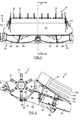
- FIGS 1 and 2 illustrate an active spreader 10 according to the present invention mounted directly behind the trajectory of the knives 14 of the chopper 12, and at an acute, downward angle relative to the outlet direction of the chopped residue.
- Chopped crop residue is thrown from the chopper knives 14 under an upward angle into the spreader entrance 22.
- the spreader 10 comprises two contra-rotating generally horizontal rotor impellers 24 for spreading chopped crop residue from the full width straw chopper 12 in a generally sideways direction over the full width of the field strip harvested by the header.
- the impellers 24 comprise a bottom plate 26, which is provided with a set of, for instance three, impeller blades 28 and mounted for rotation by a suitable motor, such as a hydraulic motor 30.
- the tips of the impeller blades 28 advantageously are provided with exchangeable wear plates.
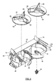
- Each movable wall portion 34 comprises a deflector plate, which is mounted for pivotment about an upright shaft 38. Its outlet direction may be adjusted manually, e.g. by set screws, or remotely by actuators that may be controlled from the operator's station or via switches on a side panel of the combine harvester.
- the wall portions 32, 34 are also slideably mounted on the upright shafts 38 for generally vertical movement by another set mechanism or actuator.
- the inner sections of the wall portions 34 have a greater height than the outer sections, adjacent the wall ends.
- the upper portion of the residue flow from the impellers 24 first follows the inner high wall sections and then fans out rearwardly and sidewardly over the inclined and curved upper ridge of the wall 34 near the outer tips.
- the lower portion of the residue flow follows the movable wall portion 34 over its full length and is projected sidewardly from the outer tips.
- the proportion of material that is fanned out and the proportion that is ejected sidewardly can be adjusted by varying the height of the movable wall portions 34. In this manner it is possible to change the distribution of crop material within the harvested field strip behind the combine harvester.
- the operator When entering a fresh field of after installing a new header, the operator has to adjust the various settings of the spreader 10. First he should vary the rotative speed of the impellers 24 until the spreading width matches the width of the header. Then he may vary the vertical position of the movable wall portions 34 to adjust the distribution of the crop residue on the field. While harvesting he may adapt the angular position of the movable wall portion 34 for compensating for the effects of side wind or side slope of the field. These conditions may result in part of the material being deposited on the unharvested crop. Moving the wall portion 34 outwardly will direct the material stream away from the crop still to be harvested.
- the operator may store various positions of the movable wall portion 34 into a memory and recall them for later resetting, e.g., after changing the harvesting direction upon reaching the end of the field. Storing and recalling may be effected through a single compensation rocker switch, whereof the operator may press the left hand side to store or recall a wind/slope compensation position for the left deflector plate and the right hand side to store or recall a wind/slope compensation position for the right deflector plate.
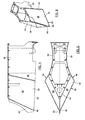
- the active spreader 10 is provided with a trunco-pyramidally shaped divider or nose splitter 50 as shown in Figures 4 to 6 .
- the symmetrical nose splitter 50 divides the chopped crop residue between the two rotor impellers 24 of the spreader.
- the shape of the nose splitter is such that the nose is wider at its lower, base side 52 than at the top side 54.
- the rear end of the lower side 52 of the nose splitter is positioned more forwardly and closer to the rotor impellers 24 than in known systems.
- the special shape prevents that the crop residue that is projected inwardly by the impeller blades 28 falls down in the space between chopper 12 and the two rotor impellers 24 of the spreader 10.
- the slope of the nose splitter 50 i.e., the angle of one of its side plates 56 to the plane of the base side 52 may be in the range between 10° and 25°, and is typically about 15°.
- the nose splitter 50 extends into the fixed wall portions 32, which are mounted parallel with respect to the axes of the rotor impellers 24.
- the zone 58 between the trunco-pyramidal shape and the parallel shape has a trapezium-like shape, as shown in Figure 4 , whereby the lower side is larger than the upper side. This implies that in that zone of the wall portion the lower side of the deflector is still wider than the top side.
- This shape enhances the flow of the crop residue in the rotor impellers.
- the wider shape at the bottom, closer to the bottom plate 26 of the impeller 24, catches the slowest and lowest crop residue preventing it from falling off, while the impeller blades 28 speed up the crop residue at an earlier instant.
- the upper shape of the deflector being further away from the rotor and smaller in size, causes minimal hindrance to the upper faster crop residue flow.
- the base side 52 of the nose splitter 50 Towards the front of the spreader 10, adjacent the straw chopper 12, the base side 52 of the nose splitter 50 has a lower tip 60, which extends more forwardly than the upper tip, at the top side 54. This enables reduction of the distance between the chopper 12 and the spreader 10 without interference of the rotating chopper knives 14 and the nose splitter 50.
- a second aspect provides the active spreader with an extended crop splitter 62 reaching as close as possible to the trajectory of the central chopper knives 14 or even in between the knives.
- the material flow from the chopper has to be split in the middle before arriving in the two spreader rotor impellers 24 of the active spreader 10.
- the central jet of crop residue flow from the chopper 12 starts to build up against the splitter or drops dead thereagainst and creates crop loss.
- a skew splitter can avoid the build-up but spills too much material on the field.
- the nose splitter 50 is extended and shaped so that it is within 10mm distance from to the rotor knives.
- Figure 4 shows a specific shape of the extension 62 on the crop or nose splitter 50, adapted to the trajectory of the chopper knives 14. In this way the shear distance between the rotor knives and the splitter does not give build-up of crop residue a chance.
- the rotating knives 14 permanently remove any trailing straws from the extension 62.
- the extension may be a single sheet of metal, or a triangular-like construction.
- the splitter extension 62 starts from inbetween the rotor knives 14.
- the active spreader splitter extends into the chopper housing.
- the shape of the splitter can be any shape as long as it does not hinder the rotor knives 14 and allows efficient splitting of the crop residue within the housing of the chopper.
- the splitter extension is provided with a cutting edge and extends towards the centre of the chopper housing, hereby also allowing split chopping.
- the active spreader 10 of the present invention is provided with a specially shaped rake 52 for swathing as shown in Figures 1 and 2 .
- the chopper 12 is bypassed and a movable swath plate inside the combine harvester (not shown) passes the crop residue on to an inclined straw guiding plate 72 above the top plate 40 covering the rotary impellers of the spreader.
- a movable swath plate inside the combine harvester passes the crop residue on to an inclined straw guiding plate 72 above the top plate 40 covering the rotary impellers of the spreader.
- the straw is deposited on the field in narrow bands.
- the rake of the present invention is provided for this purpose, but also for the purpose of effective swathing without blockage of crop residue, e.g. when wet, in the rake itself.
- Rakes 52 are mounted on each side of the plate 72 to guide the crop residue.
- Each finger 70a-c of the rake can have a shape as shown in Figures 1 to 3 , or any other suitable shape, e.g. a metal rod.
- three rake fingers 70a-c are mounted per rake.
- Figures 1 and 2 illustrate the specific vertical and horizontal positions of the rake fingers 70a-c with respect of each other.
- the rake fingers are positioned under a small upward angle to the plate 72. A preferred angle is about 5°.
- the extra space towards the lower rear side of the plate avoids blockage of crop residue underneath the lower finger 70c as the residue slides down the guiding plate 72.
- the rake 70a-c fingers are preferably parallel in horizontal direction.
- the rake fingers 70a-c are not positioned in one plane, but form an angle whereby the upper rake finger 70a is positioned most outwardly and the lower finger 70c is positioned more inwardly to the centre of the plate.
- This setup guarantees that the upper rake finger 70a slows down the crop residue less than the lower fingers 70b and 70c.
- the rake fingers are angled at 5° to 15°. This arrangement guarantees that no crop becomes caught between the diverging fingers while sliding down the guiding plate 72.
- the rakes 70 preferably are mounted for angular adjustment about an upright axis, perpendicular to the straw guiding plate 72.
- a simple, though convenient solution implies the use of a shaft 76 that is welded or otherwise connected to the front of the rake 72 and loaded downwardly by a spring 78. This spring holds the front lower edge of the rake in a notched element 80 above the guiding plate 72. This configuration allows manual adjustment without requiring further tools.
Claims (6)
- Eparpilleur de résidu de produit de récolte actif (10) pour une moissonneuse-batteuse agricole, comprenant un caisson pouvant être monté à une extrémité arrière de la moissonneuse-batteuse dans une position permettant de recevoir le résidu de produit récolté d'un mécanisme de battage et facultativement d'un mécanisme de hacheur (12), ledit éparpilleur comprenant deux roues à pâles à rotor généralement horizontales (24) permettant de guider et porter le flux déversé loin à une certaine distance de l'éparpilleur (10) et de répartir uniformément le résidu de produit récolté sur un champ et ledit éparpilleur comprenant à son entrée (22) un diviseur à pointe triangulaire (50) destiné à fractionner le résidu de produit haché entre les deux roues à pâles à rotor (24), caractérisé en ce que ledit diviseur à pointe (50) a une forme tronco-pyramidale qui est plus large à sa base inférieure (52) qu'à son sommet (54).
- Eparpilleur selon la revendication 1, caractérisé en ce que la forme pyramidale comporte des plaques latérales (56) inclinées à un angle entre 5°et 25° par rapport au plan de la base (52).
- Eparpilleur selon la revendication 1 ou 2, caractérisé en ce que la zone de transition (58) entre ledit diviseur à pointe tronco-pyramidal (50) et les déflecteurs de rotor montés en parallèle (32) a la forme d'un trapèze ayant un côté inférieur qui est plus large et plus grand que le côté supérieur.
- Combinaison d'un éparpilleur selon l'une quelconque des revendications 1 à 3 et d'un mécanisme de hacheur (12) monté sur ledit éparpilleur, caractérisée en ce que ledit diviseur à pointe (50) comprend en plus un prolongement (62) vers ledit mécanisme de hacheur.
- Combinaison selon la revendication 3, caractérisée en ce que ledit prolongement (62) a une arête avant à une distance de moins de 10 mm de la trajectoire des couteaux de rotor (14) du mécanisme de hacheur (12).
- Combinaison selon la revendication 3, caractérisée en ce que ledit prolongement (62) s'étend à l'intérieur du mécanisme de hacheur (12).
Priority Applications (7)
| Application Number | Priority Date | Filing Date | Title |
|---|---|---|---|
| AT08158965T ATE520296T1 (de) | 2008-06-25 | 2008-06-25 | Angetriebener streuer für einen mähdrescher |
| EP08158965A EP2138024B1 (fr) | 2008-06-25 | 2008-06-25 | Dissipateur actif pour moissonneuse-batteuse |
| AT09163786T ATE512581T1 (de) | 2008-06-25 | 2009-06-25 | Erntegutleiteinrichtung für das heck einer erntemaschine |
| AT09163787T ATE512582T1 (de) | 2008-06-25 | 2009-06-25 | Mähdrescher der ein gasfedersicherheitssystem umfasst |
| US12/457,000 US7927200B2 (en) | 2008-06-25 | 2009-06-25 | Agricultural combine active spreader having a triangular nose divider |
| EP09163787A EP2138026B1 (fr) | 2008-06-25 | 2009-06-25 | Moissonneuse-batteuse agricole comportant un système de sécurité avec ressort à gaz |
| EP09163786A EP2138025B1 (fr) | 2008-06-25 | 2009-06-25 | Agencement de guide de récolte pour l'arrière d'une moissonneuse agricole |
Applications Claiming Priority (1)
| Application Number | Priority Date | Filing Date | Title |
|---|---|---|---|
| EP08158965A EP2138024B1 (fr) | 2008-06-25 | 2008-06-25 | Dissipateur actif pour moissonneuse-batteuse |
Publications (2)
| Publication Number | Publication Date |
|---|---|
| EP2138024A1 EP2138024A1 (fr) | 2009-12-30 |
| EP2138024B1 true EP2138024B1 (fr) | 2011-08-17 |
Family
ID=39615603
Family Applications (3)
| Application Number | Title | Priority Date | Filing Date |
|---|---|---|---|
| EP08158965A Active EP2138024B1 (fr) | 2008-06-25 | 2008-06-25 | Dissipateur actif pour moissonneuse-batteuse |
| EP09163786A Active EP2138025B1 (fr) | 2008-06-25 | 2009-06-25 | Agencement de guide de récolte pour l'arrière d'une moissonneuse agricole |
| EP09163787A Active EP2138026B1 (fr) | 2008-06-25 | 2009-06-25 | Moissonneuse-batteuse agricole comportant un système de sécurité avec ressort à gaz |
Family Applications After (2)
| Application Number | Title | Priority Date | Filing Date |
|---|---|---|---|
| EP09163786A Active EP2138025B1 (fr) | 2008-06-25 | 2009-06-25 | Agencement de guide de récolte pour l'arrière d'une moissonneuse agricole |
| EP09163787A Active EP2138026B1 (fr) | 2008-06-25 | 2009-06-25 | Moissonneuse-batteuse agricole comportant un système de sécurité avec ressort à gaz |
Country Status (3)
| Country | Link |
|---|---|
| US (1) | US7927200B2 (fr) |
| EP (3) | EP2138024B1 (fr) |
| AT (3) | ATE520296T1 (fr) |
Families Citing this family (45)
| Publication number | Priority date | Publication date | Assignee | Title |
|---|---|---|---|---|
| SE531230C2 (sv) | 2007-06-20 | 2009-01-27 | Rekordverken Ab | Skördetröska med utloppsfläktar |
| ATE548902T1 (de) * | 2009-05-14 | 2012-03-15 | Deere & Co | Erntegutrestehäcksel und -verteilanordnung für einen mähdrescher |
| DE102009028765A1 (de) | 2009-05-14 | 2010-11-25 | Deere & Company, Moline | Erntegutrestehäcksel und -verteilanordnung für einen Mähdrescher |
| US8864561B2 (en) * | 2009-08-26 | 2014-10-21 | Deere & Company | Harvested crop residue chopper and distribution arrangement for a combine with an impeller blower whose shape conforms to the contour of the straw chopper |
| US9033780B2 (en) * | 2009-09-29 | 2015-05-19 | Cnh Industrial America Llc | Biomass feed system using an air blanket for improved distribution within a collection device |
| US8010262B2 (en) * | 2009-10-21 | 2011-08-30 | Cnh America Llc | Apparatus and method for automatically controlling the settings of an adjustable crop residue spreader of an agricultural combine |
| BE1019133A3 (nl) * | 2010-01-05 | 2012-03-06 | Cnh Belgium Nv | Een maaidorser. |
| US8118650B2 (en) * | 2010-03-24 | 2012-02-21 | Cnh America Llc | Crop residue flow distributor for an agricultural combine |
| US8430732B1 (en) | 2011-10-22 | 2013-04-30 | Cnh America Llc | V-Wedge crop deflectors |
| US8834244B2 (en) * | 2012-07-25 | 2014-09-16 | Cnh Industrial America Llc | Flow distribution system for controlling application width of residual crop material |
| US9107349B2 (en) | 2012-08-31 | 2015-08-18 | Cnh Industrial America Llc | System and method for controlling the spreading of crop residue expelled from an agricultural combine |
| US8992294B2 (en) | 2012-08-31 | 2015-03-31 | Cnh Industrial America Llc | Windrow door assembly for an agricultural combine |
| US9137944B2 (en) | 2012-08-31 | 2015-09-22 | Cnh Industrial America Llc | Windrow door for an agricultural combine |
| US9370141B2 (en) | 2012-12-11 | 2016-06-21 | Cnh Industrial America Llc | Spreader system for an agricultural harvester |
| WO2014181171A1 (fr) * | 2013-05-10 | 2014-11-13 | Agco Corporation | Procédé et système de sortie de mog de crible |
| DE102013105836A1 (de) * | 2013-06-06 | 2014-12-11 | Claas Selbstfahrende Erntemaschinen Gmbh | Mähdrescher |
| US9357703B2 (en) | 2013-07-03 | 2016-06-07 | Cnh Industrial America Llc | Pivot support member for agricultural machine |
| DE102013109983A1 (de) | 2013-09-11 | 2015-03-12 | Claas Selbstfahrende Erntemaschinen Gmbh | Mähdrescher mit einer Abscheidevorrichtung |
| CA2897880C (fr) | 2014-07-21 | 2019-09-24 | Dean Mayerle | Appareil destine a couper et a evacuer la paille d'une moissonneuse-batteuse |
| US9497903B2 (en) * | 2014-10-16 | 2016-11-22 | Agco Corporation | Combine harvester residue management system |
| US9521808B2 (en) * | 2014-11-19 | 2016-12-20 | Cnh Industrial America Llc | Harvester chaff pan assembly with moveable deflector components |
| US9801340B2 (en) * | 2015-04-30 | 2017-10-31 | Cnh Industrial America Llc | Spreader arrangement for an agricultural harvester |
| US9743586B2 (en) * | 2015-09-17 | 2017-08-29 | Agco Corporation | Mounting arrangement for a straw chopper and chaff spreader in a combine harvester residue management system |
| US10375885B2 (en) * | 2015-09-17 | 2019-08-13 | Deere & Company | System for chopping and spreading residue |
| US20170112055A1 (en) * | 2015-10-27 | 2017-04-27 | Cnh Industrial America Llc | Agricultural harvester residue spreader automation |
| US10743461B2 (en) | 2015-12-15 | 2020-08-18 | Cnh Industrial America Llc | Air assist system for spinner spreaders |
| US10159187B2 (en) * | 2016-04-04 | 2018-12-25 | James E. Straeter | Chopper assembly |
| US10595506B2 (en) * | 2016-05-26 | 2020-03-24 | Harry H. Becker | Material spreader bucket for loaders |
| RU2634279C1 (ru) * | 2016-07-25 | 2017-10-24 | Федеральное государственное бюджетное образовательное учреждение высшего профессионального образования "Кубанский государственный аграрный университет" | Устройство для разбрасывания соломы к зерноуборочному комбайну |
| US20180092302A1 (en) * | 2016-10-01 | 2018-04-05 | Deere & Company | Residue spread control using operator input of wind direction and combine bearing |
| US10934743B2 (en) | 2016-10-21 | 2021-03-02 | C.R. Laurence Co., Inc. | Taper-loc system improvements |
| US11096327B2 (en) * | 2016-11-10 | 2021-08-24 | Cnh Industrial America Llc | Crop residue spreader rotor with different paddle shapes |
| US11039574B2 (en) * | 2017-09-22 | 2021-06-22 | Deere & Company | System to reduce material accumulation on top of a power residue spreader on an agricultural combine |
| US11375661B2 (en) * | 2017-10-16 | 2022-07-05 | Deere & Company | Combine harvester and discharge assembly of the same |
| DE102018102594A1 (de) * | 2018-02-06 | 2019-08-08 | Claas Selbstfahrende Erntemaschinen Gmbh | Mähdrescher |
| US11019768B2 (en) | 2018-02-26 | 2021-06-01 | Deere & Company | Double decker crop residue spreader |
| US10827674B2 (en) * | 2018-12-12 | 2020-11-10 | Cnh Industrial America Llc | Extendable table adjusting windrow chute |
| DE102019105952A1 (de) * | 2019-03-08 | 2020-09-10 | Claas Selbstfahrende Erntemaschinen Gmbh | Häcksel- und Verteilvorrichtung |
| US11432466B2 (en) * | 2019-06-24 | 2022-09-06 | Deere & Company | Windrow system with split curtains and method thereof |
| CN112119752A (zh) * | 2019-06-24 | 2020-12-25 | 迪尔公司 | 具有分离帘幕的堆料系统及其方法 |
| US11758847B2 (en) | 2019-09-19 | 2023-09-19 | Deere & Company | Residue quality assessment and performance system for a harvester |
| US20210227749A1 (en) * | 2020-04-14 | 2021-07-29 | Super Spreader, L.L.C. | Rotary Implement for Harvester Combine Dispersal of Straw Cuttings |
| US11589506B2 (en) | 2020-04-30 | 2023-02-28 | Deere & Company | Residue management system with anti-stagnation floor extension |
| DE102020116639B4 (de) * | 2020-06-24 | 2023-12-28 | Maschinenfabrik Bernard Krone GmbH & Co. KG | Vorsatzgerät mit einer Sicherheitseinrichtung, landwirtschaftliche Arbeitsmaschine mit dem Vorsatzgerät und Verfahren zum Überführen des Vorsatzgerätes von einer Erntebetriebsanordnung in eine Straßentransportanordnung |
| US11490564B2 (en) | 2020-06-25 | 2022-11-08 | Deere & Company | Draper transport lift assist system |
Family Cites Families (22)
| Publication number | Priority date | Publication date | Assignee | Title |
|---|---|---|---|---|
| GB997865A (en) * | 1962-12-03 | 1965-07-07 | Allis Chalmers Mfg Co | Improvements in or relating to combine harvesters |
| US3232627A (en) * | 1964-01-27 | 1966-02-01 | Lester L Larson | Pattern control device for spreaders |
| US3539113A (en) * | 1968-07-09 | 1970-11-10 | Letco Inc | Distributor means for a fertilizer spreader |
| US5421777A (en) * | 1993-07-02 | 1995-06-06 | New Holland North America, Inc. | Tailings return system for combine harvester |
| US5976011A (en) * | 1997-12-31 | 1999-11-02 | Hartman; Everett A. | Straw and chaff spreader assembly |
| DE19908111C1 (de) | 1999-02-25 | 2000-07-27 | Claas Selbstfahr Erntemasch | Mähdrescher mit Breitverteileraustrag für gehäckseltes Stroh-Spreu-Gemisch |
| US6343986B1 (en) * | 1999-05-26 | 2002-02-05 | David A. Hofer | Combine straw and chaff spreader |
| DE10130652A1 (de) * | 2001-06-27 | 2003-01-30 | Claas Selbstfahr Erntemasch | Mähdrescher mit Wurfgebläse |
| DE10133965A1 (de) * | 2001-07-17 | 2003-02-13 | Claas Selbstfahr Erntemasch | Mähdrescher mit zugehörigem Häcksler und daran anschließenden Wurfgebläsen |
| US6602131B2 (en) * | 2001-12-12 | 2003-08-05 | Case Corporation | Multi-tier crop residue flow guide for an agricultural combine |
| US6547169B1 (en) * | 2002-06-25 | 2003-04-15 | Case Corporation | Crop residue spreader for an agricultural combine |
| US6769980B2 (en) * | 2002-12-30 | 2004-08-03 | Case, Llc | Crop residue flow guide with flow-through capability for a rotary crop residue spreader of an agricultural combine |
| DE10342922A1 (de) * | 2003-09-15 | 2005-05-19 | Claas Selbstfahrende Erntemaschinen Gmbh | Häcksel- und Verteilvorrichtung |
| DE10354783A1 (de) * | 2003-11-21 | 2005-07-14 | Claas Selbstfahrende Erntemaschinen Gmbh | Verfahren und Vorrichtung zum Zerkleinern und Verteilen von Erntegut |
| US6893340B1 (en) * | 2003-12-09 | 2005-05-17 | Cnh America Llc | Rotary accelerating apparatus for a vertical straw and chaff spreader of an agricultural combine |
| DE102004014306A1 (de) * | 2004-03-24 | 2005-10-27 | Deere & Company, Moline | Strohleitrechen |
| US6939221B1 (en) * | 2004-04-26 | 2005-09-06 | Redekop Chaff Systems Ltd. | Combine harvester with a spreader having independent spread width control |
| DE102005019615A1 (de) * | 2005-04-28 | 2006-11-09 | Deere & Company, Moline | Mähdrescher |
| US7331855B2 (en) | 2005-07-15 | 2008-02-19 | Deere & Company | Wide-spread impeller spreader for harvesting combine |
| US7223168B2 (en) * | 2005-08-01 | 2007-05-29 | Cnh America Llc | Adjustable crop residue flow distributor for a vertical spreader of an agricultural combine |
| US7390253B2 (en) * | 2006-05-25 | 2008-06-24 | Cnh America Llc | Flow distributor apparatus for controlling spread width of a straw spreader |
| US7553227B2 (en) * | 2007-10-31 | 2009-06-30 | Cnh America Llc | Residue splitter |
-
2008
- 2008-06-25 EP EP08158965A patent/EP2138024B1/fr active Active
- 2008-06-25 AT AT08158965T patent/ATE520296T1/de not_active IP Right Cessation
-
2009
- 2009-06-25 AT AT09163787T patent/ATE512582T1/de not_active IP Right Cessation
- 2009-06-25 AT AT09163786T patent/ATE512581T1/de not_active IP Right Cessation
- 2009-06-25 EP EP09163786A patent/EP2138025B1/fr active Active
- 2009-06-25 US US12/457,000 patent/US7927200B2/en not_active Expired - Fee Related
- 2009-06-25 EP EP09163787A patent/EP2138026B1/fr active Active
Also Published As
| Publication number | Publication date |
|---|---|
| EP2138026A1 (fr) | 2009-12-30 |
| EP2138024A1 (fr) | 2009-12-30 |
| US7927200B2 (en) | 2011-04-19 |
| ATE512582T1 (de) | 2011-07-15 |
| EP2138025A1 (fr) | 2009-12-30 |
| ATE520296T1 (de) | 2011-09-15 |
| EP2138026B1 (fr) | 2011-06-15 |
| ATE512581T1 (de) | 2011-07-15 |
| US20090325659A1 (en) | 2009-12-31 |
| EP2138025B1 (fr) | 2011-06-15 |
Similar Documents
| Publication | Publication Date | Title |
|---|---|---|
| EP2138024B1 (fr) | Dissipateur actif pour moissonneuse-batteuse | |
| US8585475B2 (en) | Crop residue distribution apparatus and system with cooperatively movable deflector door and spreader assembly | |
| US7455584B2 (en) | Method for positively discharging crop residue from a combine | |
| US7950989B2 (en) | Combine with an endless conveyor that can be moved between a swath depositing position and a chopper position | |
| US8079900B2 (en) | Harvester with an additional drum conveyor for straw removal and a single flap for changing between swath deposit and chopping operation | |
| US7896732B2 (en) | Crop residue chopping and spreading system for an agricultural combine | |
| EP2521434B1 (fr) | Moissonneuse-batteuse | |
| US8128467B2 (en) | Crop residue chopping and spreading arrangement for a combine harvester | |
| EP3409095B1 (fr) | Moissonneuse-batteuse agricole comportant un rotor de hacheur inversé | |
| EP2993968B1 (fr) | Installation de hacheur/ventilateur pour un organe de coupe utilisé sur une récolteuse agricole | |
| CN109640619B (zh) | 用于农作物收割机的作物残余物撒布器 | |
| EP3087818B1 (fr) | Système d'épandage pour une moissonneuse agricole | |
| US10398081B2 (en) | Straw spreader and chaff spreader for a combine harvester | |
| EP3345472B1 (fr) | Dissipateur de résidus de cultures pour moissonneuse-batteuse | |
| EP4173466A1 (fr) | Système d'épandeuse réglable pour une moissonneuse agricole | |
| WO2018089796A1 (fr) | Rotor d'épandeur de résidu de récolte avec différentes formes de pales |
Legal Events
| Date | Code | Title | Description |
|---|---|---|---|
| PUAI | Public reference made under article 153(3) epc to a published international application that has entered the european phase |
Free format text: ORIGINAL CODE: 0009012 |
|
| AK | Designated contracting states |
Kind code of ref document: A1 Designated state(s): AT BE BG CH CY CZ DE DK EE ES FI FR GB GR HR HU IE IS IT LI LT LU LV MC MT NL NO PL PT RO SE SI SK TR |
|
| AX | Request for extension of the european patent |
Extension state: AL BA MK RS |
|
| 17P | Request for examination filed |
Effective date: 20100630 |
|
| 17Q | First examination report despatched |
Effective date: 20100726 |
|
| AKX | Designation fees paid |
Designated state(s): AT BE BG CH CY CZ DE DK EE ES FI FR GB GR HR HU IE IS IT LI LT LU LV MC MT NL NO PL PT RO SE SI SK TR |
|
| GRAP | Despatch of communication of intention to grant a patent |
Free format text: ORIGINAL CODE: EPIDOSNIGR1 |
|
| GRAS | Grant fee paid |
Free format text: ORIGINAL CODE: EPIDOSNIGR3 |
|
| GRAA | (expected) grant |
Free format text: ORIGINAL CODE: 0009210 |
|
| AK | Designated contracting states |
Kind code of ref document: B1 Designated state(s): AT BE BG CH CY CZ DE DK EE ES FI FR GB GR HR HU IE IS IT LI LT LU LV MC MT NL NO PL PT RO SE SI SK TR |
|
| REG | Reference to a national code |
Ref country code: GB Ref legal event code: FG4D |
|
| REG | Reference to a national code |
Ref country code: CH Ref legal event code: EP |
|
| REG | Reference to a national code |
Ref country code: IE Ref legal event code: FG4D |
|
| REG | Reference to a national code |
Ref country code: DE Ref legal event code: R096 Ref document number: 602008008895 Country of ref document: DE Effective date: 20111020 |
|
| REG | Reference to a national code |
Ref country code: NL Ref legal event code: VDEP Effective date: 20110817 |
|
| LTIE | Lt: invalidation of european patent or patent extension |
Effective date: 20110817 |
|
| PG25 | Lapsed in a contracting state [announced via postgrant information from national office to epo] |
Ref country code: PT Free format text: LAPSE BECAUSE OF FAILURE TO SUBMIT A TRANSLATION OF THE DESCRIPTION OR TO PAY THE FEE WITHIN THE PRESCRIBED TIME-LIMIT Effective date: 20111219 Ref country code: LT Free format text: LAPSE BECAUSE OF FAILURE TO SUBMIT A TRANSLATION OF THE DESCRIPTION OR TO PAY THE FEE WITHIN THE PRESCRIBED TIME-LIMIT Effective date: 20110817 Ref country code: SE Free format text: LAPSE BECAUSE OF FAILURE TO SUBMIT A TRANSLATION OF THE DESCRIPTION OR TO PAY THE FEE WITHIN THE PRESCRIBED TIME-LIMIT Effective date: 20110817 Ref country code: FI Free format text: LAPSE BECAUSE OF FAILURE TO SUBMIT A TRANSLATION OF THE DESCRIPTION OR TO PAY THE FEE WITHIN THE PRESCRIBED TIME-LIMIT Effective date: 20110817 Ref country code: NO Free format text: LAPSE BECAUSE OF FAILURE TO SUBMIT A TRANSLATION OF THE DESCRIPTION OR TO PAY THE FEE WITHIN THE PRESCRIBED TIME-LIMIT Effective date: 20111117 Ref country code: NL Free format text: LAPSE BECAUSE OF FAILURE TO SUBMIT A TRANSLATION OF THE DESCRIPTION OR TO PAY THE FEE WITHIN THE PRESCRIBED TIME-LIMIT Effective date: 20110817 Ref country code: IS Free format text: LAPSE BECAUSE OF FAILURE TO SUBMIT A TRANSLATION OF THE DESCRIPTION OR TO PAY THE FEE WITHIN THE PRESCRIBED TIME-LIMIT Effective date: 20111217 |
|
| REG | Reference to a national code |
Ref country code: AT Ref legal event code: MK05 Ref document number: 520296 Country of ref document: AT Kind code of ref document: T Effective date: 20110817 |
|
| PG25 | Lapsed in a contracting state [announced via postgrant information from national office to epo] |
Ref country code: CY Free format text: LAPSE BECAUSE OF FAILURE TO SUBMIT A TRANSLATION OF THE DESCRIPTION OR TO PAY THE FEE WITHIN THE PRESCRIBED TIME-LIMIT Effective date: 20110817 Ref country code: PL Free format text: LAPSE BECAUSE OF FAILURE TO SUBMIT A TRANSLATION OF THE DESCRIPTION OR TO PAY THE FEE WITHIN THE PRESCRIBED TIME-LIMIT Effective date: 20110817 Ref country code: AT Free format text: LAPSE BECAUSE OF FAILURE TO SUBMIT A TRANSLATION OF THE DESCRIPTION OR TO PAY THE FEE WITHIN THE PRESCRIBED TIME-LIMIT Effective date: 20110817 Ref country code: GR Free format text: LAPSE BECAUSE OF FAILURE TO SUBMIT A TRANSLATION OF THE DESCRIPTION OR TO PAY THE FEE WITHIN THE PRESCRIBED TIME-LIMIT Effective date: 20111118 Ref country code: SI Free format text: LAPSE BECAUSE OF FAILURE TO SUBMIT A TRANSLATION OF THE DESCRIPTION OR TO PAY THE FEE WITHIN THE PRESCRIBED TIME-LIMIT Effective date: 20110817 Ref country code: LV Free format text: LAPSE BECAUSE OF FAILURE TO SUBMIT A TRANSLATION OF THE DESCRIPTION OR TO PAY THE FEE WITHIN THE PRESCRIBED TIME-LIMIT Effective date: 20110817 |
|
| PG25 | Lapsed in a contracting state [announced via postgrant information from national office to epo] |
Ref country code: CZ Free format text: LAPSE BECAUSE OF FAILURE TO SUBMIT A TRANSLATION OF THE DESCRIPTION OR TO PAY THE FEE WITHIN THE PRESCRIBED TIME-LIMIT Effective date: 20110817 Ref country code: SK Free format text: LAPSE BECAUSE OF FAILURE TO SUBMIT A TRANSLATION OF THE DESCRIPTION OR TO PAY THE FEE WITHIN THE PRESCRIBED TIME-LIMIT Effective date: 20110817 |
|
| PG25 | Lapsed in a contracting state [announced via postgrant information from national office to epo] |
Ref country code: EE Free format text: LAPSE BECAUSE OF FAILURE TO SUBMIT A TRANSLATION OF THE DESCRIPTION OR TO PAY THE FEE WITHIN THE PRESCRIBED TIME-LIMIT Effective date: 20110817 Ref country code: RO Free format text: LAPSE BECAUSE OF FAILURE TO SUBMIT A TRANSLATION OF THE DESCRIPTION OR TO PAY THE FEE WITHIN THE PRESCRIBED TIME-LIMIT Effective date: 20110817 |
|
| PLBE | No opposition filed within time limit |
Free format text: ORIGINAL CODE: 0009261 |
|
| STAA | Information on the status of an ep patent application or granted ep patent |
Free format text: STATUS: NO OPPOSITION FILED WITHIN TIME LIMIT |
|
| PG25 | Lapsed in a contracting state [announced via postgrant information from national office to epo] |
Ref country code: DK Free format text: LAPSE BECAUSE OF FAILURE TO SUBMIT A TRANSLATION OF THE DESCRIPTION OR TO PAY THE FEE WITHIN THE PRESCRIBED TIME-LIMIT Effective date: 20110817 |
|
| 26N | No opposition filed |
Effective date: 20120521 |
|
| PG25 | Lapsed in a contracting state [announced via postgrant information from national office to epo] |
Ref country code: HR Free format text: LAPSE BECAUSE OF FAILURE TO SUBMIT A TRANSLATION OF THE DESCRIPTION OR TO PAY THE FEE WITHIN THE PRESCRIBED TIME-LIMIT Effective date: 20120321 |
|
| REG | Reference to a national code |
Ref country code: DE Ref legal event code: R097 Ref document number: 602008008895 Country of ref document: DE Effective date: 20120521 |
|
| PG25 | Lapsed in a contracting state [announced via postgrant information from national office to epo] |
Ref country code: MC Free format text: LAPSE BECAUSE OF NON-PAYMENT OF DUE FEES Effective date: 20120630 |
|
| REG | Reference to a national code |
Ref country code: CH Ref legal event code: PL |
|
| REG | Reference to a national code |
Ref country code: CH Ref legal event code: PL |
|
| REG | Reference to a national code |
Ref country code: IE Ref legal event code: MM4A |
|
| PG25 | Lapsed in a contracting state [announced via postgrant information from national office to epo] |
Ref country code: CH Free format text: LAPSE BECAUSE OF NON-PAYMENT OF DUE FEES Effective date: 20120630 Ref country code: LI Free format text: LAPSE BECAUSE OF NON-PAYMENT OF DUE FEES Effective date: 20120630 Ref country code: IE Free format text: LAPSE BECAUSE OF NON-PAYMENT OF DUE FEES Effective date: 20120625 Ref country code: ES Free format text: LAPSE BECAUSE OF FAILURE TO SUBMIT A TRANSLATION OF THE DESCRIPTION OR TO PAY THE FEE WITHIN THE PRESCRIBED TIME-LIMIT Effective date: 20111128 |
|
| PG25 | Lapsed in a contracting state [announced via postgrant information from national office to epo] |
Ref country code: BG Free format text: LAPSE BECAUSE OF FAILURE TO SUBMIT A TRANSLATION OF THE DESCRIPTION OR TO PAY THE FEE WITHIN THE PRESCRIBED TIME-LIMIT Effective date: 20111117 |
|
| PG25 | Lapsed in a contracting state [announced via postgrant information from national office to epo] |
Ref country code: MT Free format text: LAPSE BECAUSE OF FAILURE TO SUBMIT A TRANSLATION OF THE DESCRIPTION OR TO PAY THE FEE WITHIN THE PRESCRIBED TIME-LIMIT Effective date: 20110817 |
|
| PG25 | Lapsed in a contracting state [announced via postgrant information from national office to epo] |
Ref country code: HR Free format text: LAPSE BECAUSE OF FAILURE TO SUBMIT A TRANSLATION OF THE DESCRIPTION OR TO PAY THE FEE WITHIN THE PRESCRIBED TIME-LIMIT Effective date: 20110817 |
|
| REG | Reference to a national code |
Ref country code: DE Ref legal event code: R082 Ref document number: 602008008895 Country of ref document: DE Representative=s name: PATENTANWAELTE WALLACH, KOCH & PARTNER, DE |
|
| PG25 | Lapsed in a contracting state [announced via postgrant information from national office to epo] |
Ref country code: TR Free format text: LAPSE BECAUSE OF FAILURE TO SUBMIT A TRANSLATION OF THE DESCRIPTION OR TO PAY THE FEE WITHIN THE PRESCRIBED TIME-LIMIT Effective date: 20110817 |
|
| PG25 | Lapsed in a contracting state [announced via postgrant information from national office to epo] |
Ref country code: LU Free format text: LAPSE BECAUSE OF NON-PAYMENT OF DUE FEES Effective date: 20120625 |
|
| REG | Reference to a national code |
Ref country code: DE Ref legal event code: R081 Ref document number: 602008008895 Country of ref document: DE Owner name: CNH INDUSTRIAL BELGIUM NV, BE Free format text: FORMER OWNER: CNH BELGIUM NV, ZEDELGEM, BE Effective date: 20140428 Ref country code: DE Ref legal event code: R082 Ref document number: 602008008895 Country of ref document: DE Representative=s name: PATENTANWAELTE WALLACH, KOCH & PARTNER, DE Effective date: 20140428 Ref country code: DE Ref legal event code: R082 Ref document number: 602008008895 Country of ref document: DE Representative=s name: PATENTANWAELTE WALLACH, KOCH, DR. HAIBACH, FEL, DE Effective date: 20140428 |
|
| PG25 | Lapsed in a contracting state [announced via postgrant information from national office to epo] |
Ref country code: HU Free format text: LAPSE BECAUSE OF FAILURE TO SUBMIT A TRANSLATION OF THE DESCRIPTION OR TO PAY THE FEE WITHIN THE PRESCRIBED TIME-LIMIT Effective date: 20080625 |
|
| REG | Reference to a national code |
Ref country code: FR Ref legal event code: CD Owner name: CNH INDUSTRIAL BELGIUM NV Effective date: 20140725 |
|
| REG | Reference to a national code |
Ref country code: FR Ref legal event code: PLFP Year of fee payment: 9 |
|
| REG | Reference to a national code |
Ref country code: FR Ref legal event code: PLFP Year of fee payment: 10 |
|
| REG | Reference to a national code |
Ref country code: FR Ref legal event code: PLFP Year of fee payment: 11 |
|
| REG | Reference to a national code |
Ref country code: DE Ref legal event code: R082 Ref document number: 602008008895 Country of ref document: DE Representative=s name: MEISSNER BOLTE PATENTANWAELTE RECHTSANWAELTE P, DE |
|
| PGFP | Annual fee paid to national office [announced via postgrant information from national office to epo] |
Ref country code: IT Payment date: 20230613 Year of fee payment: 16 Ref country code: FR Payment date: 20230623 Year of fee payment: 16 Ref country code: DE Payment date: 20230627 Year of fee payment: 16 |
|
| PGFP | Annual fee paid to national office [announced via postgrant information from national office to epo] |
Ref country code: BE Payment date: 20230630 Year of fee payment: 16 |
|
| PGFP | Annual fee paid to national office [announced via postgrant information from national office to epo] |
Ref country code: GB Payment date: 20230622 Year of fee payment: 16 |