EP2137361B1 - Wandrahmensystem - Google Patents
Wandrahmensystem Download PDFInfo
- Publication number
- EP2137361B1 EP2137361B1 EP07847644.7A EP07847644A EP2137361B1 EP 2137361 B1 EP2137361 B1 EP 2137361B1 EP 07847644 A EP07847644 A EP 07847644A EP 2137361 B1 EP2137361 B1 EP 2137361B1
- Authority
- EP
- European Patent Office
- Prior art keywords
- stud
- side walls
- stud member
- locking
- channel
- Prior art date
- Legal status (The legal status is an assumption and is not a legal conclusion. Google has not performed a legal analysis and makes no representation as to the accuracy of the status listed.)
- Not-in-force
Links
Images

Classifications
-
- E—FIXED CONSTRUCTIONS
- E04—BUILDING
- E04B—GENERAL BUILDING CONSTRUCTIONS; WALLS, e.g. PARTITIONS; ROOFS; FLOORS; CEILINGS; INSULATION OR OTHER PROTECTION OF BUILDINGS
- E04B2/00—Walls, e.g. partitions, for buildings; Wall construction with regard to insulation; Connections specially adapted to walls
- E04B2/74—Removable non-load-bearing partitions; Partitions with a free upper edge
- E04B2/76—Removable non-load-bearing partitions; Partitions with a free upper edge with framework or posts of metal
- E04B2/766—T-connections
- E04B2/767—Connections between wall studs and upper or lower locating rails
-
- E—FIXED CONSTRUCTIONS
- E04—BUILDING
- E04B—GENERAL BUILDING CONSTRUCTIONS; WALLS, e.g. PARTITIONS; ROOFS; FLOORS; CEILINGS; INSULATION OR OTHER PROTECTION OF BUILDINGS
- E04B2/00—Walls, e.g. partitions, for buildings; Wall construction with regard to insulation; Connections specially adapted to walls
- E04B2/74—Removable non-load-bearing partitions; Partitions with a free upper edge
- E04B2/76—Removable non-load-bearing partitions; Partitions with a free upper edge with framework or posts of metal
-
- E—FIXED CONSTRUCTIONS
- E04—BUILDING
- E04B—GENERAL BUILDING CONSTRUCTIONS; WALLS, e.g. PARTITIONS; ROOFS; FLOORS; CEILINGS; INSULATION OR OTHER PROTECTION OF BUILDINGS
- E04B2/00—Walls, e.g. partitions, for buildings; Wall construction with regard to insulation; Connections specially adapted to walls
- E04B2/74—Removable non-load-bearing partitions; Partitions with a free upper edge
Definitions
- the invention relates to a wall framing system, comprising:
- the invention also relates to a stud member for use in a wall framing system, said stud member having a floor portion and a pair of side walls upstanding from said floor portion.
- the invention further relates to a method of assembling a wall framing system, comprising:
- the invention relates to a method of manufacturing a stud member for a wall framing system.
- the invention relates to a method of joining stud members into a length-adjustable stud member.
- a wall framing system which is easy to assemble and has adequate positioning means to provide a certain relative positioning of separate members forming part of the framing system.
- a wall framing system comprises channel members to be fastened to a wall, a floor, a ceiling or to configure a border to for example a door opening or a window opening or the like.
- the framing system further comprises stud members, which stud members are to be placed between the channel members in either a vertical manner or a horizontal manner.
- the stud member When bending these flaps and thereby preventing the movement of the stud in a direction away from the flaps, the stud member is secured in the channel member.
- the disadvantage of such a system is that the stud member can be placed only at predetermined locations in the channel member.
- the clip bracket is provided with tongues for insertion through an open top or bottom of an impression adjacent the inner face of the respective wall.
- the tongues are ganged together by a bridging arm for simultaneous insertion of a pair of through the openings in a confronting pair of impressions.
- Using the wall frame system according to US 5,325,651 also entails that the stud member can be placed only at predetermined locations in the channel member, the locations being where the impressions of the channel member are positioned in apertures in the stud member and locked by the clip bracket.
- US 3.536.345 describes a channel member where the side walls are resilient and the upper parts of the side walls are bent inwardly to provide an access opening of less width than the width of the stud member (studs).
- Each of the sidewalls is provided at selected intervals with stud receiving pockets comprising inwardly punched protrusions or lugs.
- the problems to be solved by the present invention are to eliminate the use of fastening means such as screws, nails, rivets or the like, since they are time consuming to use, and to provide a stepless and flexible way to fasten a stud member to a channel member.
- Another object of the invention is to provide an improved arrangement for connecting a wall framing system.
- the width of the stud member corresponds more or less to the inner opening of the C shape or profile of the channel member, it is possible to provide an adequate assembly.
- the side walls of the stud member in an embodiment of the invention can be provided with flanges extending towards each other.
- the flanges can be arranged on edges of the side walls in an embodiment of the invention.
- the stud member in the wall framing system can be positioned fixed in the channel member by positioning the locking means or locking member in the locking position thereby exerting a force substantially perpendicular to an inner side of the side walls of the stud, and thereby providing an outer side of the side walls exerting a force substantially perpendicular to an inner side of the side walls of the channel member, placing the stud in a fixed position relative to the channel member.
- the stud is a metal stud member.
- the locking member is attached to the stud member.
- the locking member can be moveable between an un-locked position and a locked position, where it is fixating the stud member in the channel member.
- the stud member can be positioned and locked in any position in the channel member.
- the locking member can be a knock-out opening.
- one or more knock-out openings can be situated in the stud member.
- one or more knock-out openings can be situated in the floor portion of the stud member.
- the stud member can be delivered in standard lengths and subsequently be cut into a needed length, still having locking means to engage with the stud member and fix the stud member in the channel member at a desired position.
- the knock-out opening can be situated in the channel member.
- the knock-out opening can be situated even in the floor portion of the channel member.
- a further solution to the above problems is to provide a stud member for use in a framing system, said stud member having a floor portion and a pair of side walls upstanding from said floor portion, where said stud member is provided with locking members formed by a knock out opening for engagement of said side walls such that, when a locking member is engaged with the stud member, the outer surfaces of the side walls of the stud member are pressed against the inner surfaces of the side walls of the channel member thereby achieving a frictional engagement between the contacting surfaces of the stud member and the channel member.
- the stud member can be positioned and locked in any position in the channel member in a flexible and handy way.
- the locking member is one or more knock-out openings.
- the knock-out opening can be situated in the stud member.
- the knock-out opening can be situated in the floor portion of the stud member.
- the knock-out opening is situated in a side wall of the stud member
- the side walls of the stud member in an embodiment of the invention can be provided with flanges extending towards each other.
- the flanges can be arranged on edges of the side walls in an embodiment of the invention.
- An expedient way of providing the profiles of stud members with locking members is achieved according to the invention by the method of manufacturing a stud member for a wall framing system, which method comprises the steps of:
- the tool that performs the cutting and/or punching action is advanced at substantially the same velocity along with the stud members to be cut and punched.
- a further advantage of the locking members in the stud member is a possibility to join two stud members into a telescopic member.
- FIG 1 a wall framing system 1 according to an embodiment of the invention.
- the wall framing system 1 comprises a channel member 2 with a floor portion 3 and a pair of side walls 4, 5 upstanding from said floor portion 3, a stud member 6 also having a floor portion 7 and a pair of side walls 8, 9 upstanding from said floor portion 7 for interconnection with said channel member 2, the stud member 6 being insertable between said side walls 4, 5 of the channel member 2.
- the wall framing system 1 further comprises locking means 10 for fixating the stud member 6 to the channel member 2.
- Such locking means 10 can be made up of one or more plate members 10 attached to the stud member 6.
- the locking member 10 is fixed to the floor portion 7 of the stud member 6 such that, when placing the locking means, i.e. the plate member 10 in its locking position, it is exerting a force substantially perpendicular to an inner side 11, 12 of the side walls 8, 9 of the stud 6, and thereby provides an outer side 13, 14 of the side walls 8, 9 exerting a force-substantially-perpendicular to an inner side 15, 16 of the side walls 4, 5 of the channel member 2, thus fixating the stud 6 relative to the channel member 2.
- the locking means i.e. the plate member 10 in its locking position
- the locking means 10 can be placed in or on the inner side 11, 12 of the side walls 8, 9.
- the locking members 10 press against each other or press against the floor portion 7 exerting a force substantially perpendicular to the inner side 11, 12 of the side walls 8, 9 of the stud 6, and thereby provide the outer side 13, 14 of the side walls 8, 9 exerting a force substantially perpendicular to the inner side 15, 16 of the side walls 4, 5 of the channel member 2, placing the stud 6 in a fixed position relative to the channel member 2.
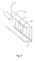
- FIG 4 is shown a further embodiment of the invention where the channel member 2 is provided with knock-out openings 17, which knock-out openings 17 are to be used as an aid for positioning the stud member 6 in the channel member 2.
- a knock-out opening 17 can be explained as an opening where three in four sides of a flap are cut or punched out or nearly cut or punched out in such a way that the flap can be bent over the side of the flap still connected to the surface from which the knock out opening is made.
- the knock-out openings 17 are situated in the floor portion 3 of the channel member 2. Such a knock-out opening 17 can also engage with the side walls 8, 9 of the stud member 6, when a stud member 6 is positioned close to the knock-out opening 17.
- the flap 20 from the knock-out opening 17 can act as locking means able to exert a force on the inner surface 11, 12 of the side walls 8, 9 of the stud member 6 such that, when the flap 20 from the knock-out opening 17 is engaged with the stud member 6, the outer surfaces 13, 14 of the side walls 8, 9 of the stud member 6 are pressed against the inner surfaces 15, 16 of the side walls 4, 5 of the channel member 2 thereby achieving a frictional engagement between the contacting surfaces of the stud member 6 and the channel member 2.
- the side walls 8, 9 of the stud member 6 can be provided with flanges 108, 109 extending from the side walls 8, 9 towards each other.
- the flanges 108, 109 can be arranged on edges of the side walls to achieve a high moment.
- the stud member 6 is preferably produced from a rigid material such as metal.
- one or more locking members 10 is/are attached to the stud member 6.
- one or more locking members 10 is/are moveable between an un-locked position and a locked position, in which locked position the stud member 6 is fixated in the channel member 2.
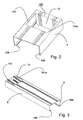
- the locking member 10 is bent over an edge 102.
- a pair of notches is formed (pre-cut). These notches corresponding to a pair of small projections 101, 101 a form a kind of holding means for holding the locking member in locked position.
- the distance from the bending edge 102 to one projection 101 is different from the distance from the bending edge 102 to the other projection 101a. In this embodiment these particular distances correspond to different heights of the side walls 8, 9.
- the flanges 108, 109 can engage with the notches in the locking member to hold the locking member into the engaged position as shown in figure 2 .
- a method of assembling a wall framing system as described above comprises the steps of:
- a method of manufacturing locking members in stud members and a tool for manufacturing the locking members in stud members are provided.
- the profiled stud member 6 is advanced through a tool, which tool is performing three operations at a time.
- the first operation punches out a flap forming a locking member 10 which is held in place by a bending edge 102 allowing the flap to be bent backwards and forwards in relation to its current position.
- the punching out of the flap can leave a number of points along the bending line or a line with reduced thickness of material can form the bending line in such a way that it is possible to bend the locking member 10 in relation to the floor portion 7 of the stud member 6 and it still is possible to have the locking member attached to the stud member 6 along an edge 102 of the locking member 10.
- the bending edge 102 produced by the first operation is placed in the direction of the flap 10 being most forward in the operational direction.
- the punch or the contact surface of the punch creating the flap 10 is positioned in an inclining position in relation to the floor portion 7 of the stud member 6. This inclined position leads to a reduced need for force to perform the punching.
- a spring biased ejector or an ejector with resilient means is provided for bringing back the punching form or die to its original position and thereby positioning the flap 10 in a position aligned with the floor portion 7 of the stud member 6 in such a way that it is possible for the stud member 6 to pass through the rest of the parts of the tool without getting stuck.
- the second operation is performed, the second operation being a cutting operation.
- the tool is placed on a kind of slide able to be advanced together with, and at the same velocity as, the profile to be cut and punched.
- the tool is placed on a kind of slide able to be advanced together with, and at the same velocity as, the profile to be cut and punched.
- the tool is advanced by the slide at the same velocity as the profile until the process for manufacturing a stud member profile has ended. Then the slide will return to its starting point and there await a signal or impulse initiating the next cutting and punching cycle.
- a further advantage of having a stud member 6 provided with one or more locking members 10 in the form of knock-out openings is a possibility to join two stud members 6 into a telescopic member.
- Each stud member 6 is provided with flanges 108, 109 arranged on edges of the side walls 8, 9.
- flanges 108, 109 arranged on edges of the side walls 8, 9.
- Figure 2 and figure 3 show an embodiment, where the side wall 9 extends further from the floor portion 7 than the side wall 8.
- the one side wall 8 extends a distance corresponding in such a way that the outer dimension of the one side wall 8 of the stud member 6 measured from the outer side of the underside of the floor portion 7 to the outer side of the upper side of the flange 108 is equal to or smaller than the inner dimension of the other side wall 9 of the stud member measured from the inner side of the floor portion 7 to the inner side of the lower side of the flange 109.
- the two stud members 6 are dimensioned to be able to "snap" into each other when joined into each other's open profile.
- the locking members of the stud members can be activated by pressure by hand or a simple tool, i.e. a shaft from a hammer, a spirit level, a screwdriver or the like.
- the length of the joined stud member is fixated and the joined stud member can be placed in an upper and a lower-channel member as if the joined stud member is a single stud member with the correct length for positioning it in the two channel members.
- two stud members each of 150 cm can be joined to a telescopic member which can cover lengths from approximately 170 cm to 280 cm.
Landscapes
- Engineering & Computer Science (AREA)
- Architecture (AREA)
- Physics & Mathematics (AREA)
- Electromagnetism (AREA)
- Civil Engineering (AREA)
- Structural Engineering (AREA)
- Joining Of Building Structures In Genera (AREA)
- Assembled Shelves (AREA)
- Load-Bearing And Curtain Walls (AREA)
- Forklifts And Lifting Vehicles (AREA)
- Body Structure For Vehicles (AREA)
- Mirrors, Picture Frames, Photograph Stands, And Related Fastening Devices (AREA)
- Residential Or Office Buildings (AREA)
Claims (22)
- Wandrahmensystem (1), umfassend:- ein Kanalglied (2) mit einem Bodenabschnitt (3) und einem Paar Seitenwänden (4, 5), die vom Bodenabschnitt (3) hochstehen;- ein Ansatzglied (6) mit einem Bodenabschnitt (7) und einem Paar Seitenwänden (8, 9), die vom Bodenabschnitt (7) hochstehen, zur Verbindung mit dem Kanalglied (2), wobei das Ansatzglied (6) zwischen die Seitenwände (4, 5) des Kanalglieds (2) einführbar ist; und- Sperrmittel (10) zur Fixierung des Ansatzglieds (6) am Kanalglied (2),dadurch gekennzeichnet, dass die Sperrmittel (10) ein oder mehr Sperrglieder (10) enthalten, wobei jedes Sperrglied (10) durch eine Ausschlagöffnung (17) ausgebildet ist und zum Ausüben einer Kraft auf Innenflächen (11, 12) der Seitenwände (8, 9) des Ansatzglieds (6) angeordnet sind, sodass, wenn das Sperrglied (10) mit dem Ansatzglied (6) in Eingriff steht, Außenflächen (13, 14) der Wände (8, 9) des Ansatzglieds (6) an Innenflächen (15, 16) der Seitenwände (4, 5) des Kanalglieds (2) gepresst sind, wodurch ein Reibungseingriff zwischen sich berührenden Flächen des Ansatzglieds (6) und des Kanalglieds (2) erzielt ist.
- Wandrahmensystem nach Anspruch 1, wobei die Seitenwände (8, 9) des Ansatzglieds (6) mit Flanschen (108, 109) versehen sind, die zueinander hin verlaufen.
- Wandrahmensystem nach Anspruch 2, wobei die Flansche (108, 109) an Kanten der Seitenwände (8, 9) des Ansatzglieds (6) angeordnet sind.
- Wandrahmensystem (1) nach Anspruch 1, wobei das Sperrglied (10),wenn es in einer gesperrten Position angeordnet ist, eine Kraft im Wesentlichen senkrecht auf die Innenseite (11, 12) der Seitenwände (8, 9) des Ansatzglieds (6) ausübt, wodurch die Außenseite (13, 14) der Seitenwände (8, 9) des Ansatzglieds (6) eine Kraft im Wesentlichen senkrecht auf die Innenseite (15, 16) der Seitenwände (4, 5) des Kanalglieds (2) ausübt, wodurch das Ansatzglied (6) in einer starren Position bezüglich des Kanalglieds (2) angeordnet ist.
- Wandrahmensystem (1) nach einem der Ansprüche1 - 4, wobei das Ansatzglied (6) ein Metallansatzglied ist.
- Wandrahmensystem (1) nach einem der Ansprüche 1 - 5, wobei das Sperrglied (10) am Ansatzglied (6) angebracht ist.
- Wandrahmensystem (1) nach einem der Ansprüche 1 - 6, wobei das Sperrglied (10) zwischen einer entsperrten Position und einer gesperrten Position beweglich ist, in der das Ansatzglied (6) im Kanalglied (2) fixiert ist.
- Wandrahmensystem (1) nach einem der Ansprüche 1 - 7, wobei sich die Ausschlagöffnung (17) im Ansatzglied (6) befindet.
- Wandrahmensystem (1) nach Anspruch 8, wobei sich die Ausschlagöffnung (17) im Bodenabschnitt (7) des Ansatzglieds (6) befindet.
- Wandrahmensystem (1) nach einem der Ansprüche 1 - 9, wobei eine der Seitenwände (8, 9) des Ansatzglieds (6) weiter vom Bodenabschnitt (7) des Ansatzglieds (6) als die andere Seitenwand (8, 9) des Ansatzglieds (6) verläuft.
- Wandrahmensystem (1) nach Anspruch 1, wobei sich die Ausschlagöffnung (17) im Bodenabschnitt (3) des Kanalglieds (2) befindet.
- Ansatzglied (6) zum Gebrauch in einem Wandrahmensystem (1) nach Anspruch 1, wobei das Ansatzglied (6) einen Bodenabschnitt (7) und ein Paar Seitenwände (8, 9) umfasst, die vom Bodenabschnitt (7) hochstehen, wobei das Ansatzglied (6) ferner ein oder mehr Sperrglieder (10) umfasst, dadurch gekennzeichnet, dass jedes Sperrglied (10) durch eine Ausschlagöffnung (17) ausgebildet ist und zur Ineingriffnahme der Seitenwände (8, 9) des Ansatzglieds (6) angeordnet ist, sodass, wenn ein Sperrglied (10) mit den Seitenwänden des Ansatzglieds (6) in Eingriff steht, die Außenflächen (13, 14) der Seitenwände (8, 9) des Ansatzglieds (6) an die Innenflächen (15, 16) der Seitenwände (4, 5) eines Kanalglieds (2) des Systems gepresst sind, wodurch ein Reibungseingriff zwischen sich berührenden Flächen des Ansatzglieds (6) und des Kanalglieds (2) erzielt ist.
- Ansatzglied (6) nach Anspruch 12, wobei das eine oder mehr Sperrglieder (10) mehr als ein Sperrglied (10) umfassen.
- Ansatzglied (6) nach einem der Ansprüche 12 oder 13, wobei sich die Ausschlagöffnung (17) im Bodenabschnitt (7) des Ansatzglieds (6) befindet.
- Ansatzglied (6) nach einem der Ansprüche 12 bis 14, wobei die Seitenwände (8, 9) des Ansatzglieds (6) mit Flanschen (108, 109) versehen sind, die zueinander hin verlaufen.
- Ansatzglied (6) nach Anspruch 15, wobei die Flansche (108, 109) an Kanten der Seitenwände (8, 9) des Ansatzglieds (6) angeordnet sind.
- Ansatzglied (6) nach Anspruch 16, wobei eine der Seitenwände (8, 9) weiter vom Bodenabschnitt (7) des Ansatzglieds (6) als die andere Seitenwand (8, 9) verläuft.
- Verfahren zum Zusammenbauen eines Wandrahmensystems (1), das System umfassend:- ein Kanalglied (2) mit einem Bodenabschnitt (3) und einem Paar Seitenwänden (4, 5), die vom Bodenabschnitt (3) hochstehen;- ein Ansatzglied (6) mit einem Bodenabschnitt (7) und einem Paar Seitenwänden (8, 9), die vom Bodenabschnitt (7) hochstehen, zur Verbindung mit dem Kanalglied (2), wobei das Ansatzglied (6) zwischen die Seitenwände (4, 5) des Kanalglieds (2) einführbar ist; und- Sperrmittel (10) zum Fixieren des Ansatzglieds (6) am Kanalglied (2),wobei das Sperrglied (10) durch eine Ausschlagöffnung ausgebildet ist,folgende Schritte umfassend:- Befestigen des Kanalglieds (2) an einer Gebäudestruktur, wie etwa einem Boden, einer Wand, einer Decke oder dergleichen;- derartiges Anordnen des Ansatzglieds (6) zwischen Seitenwänden (4, 5) des Kanalglieds (2), dass die Seitenwände (8, 9) des Ansatzglieds (6) im Wesentlichen parallel mit den Seitenwänden (4, 5) des Kanalglieds (2) sind; und- Fixieren des Ansatzglieds (6) im Kanalglied (2) durch Bewegen des Sperrglieds (10) aus einer entsperrten Position in eine gesperrte Position, wodurch ein Reibungseingriff zwischen den sich berührenden Flächen des Ansatzglieds (6) und des Kanalglieds (2) erzielt wird.
- Verfahren nach Anspruch 18, wobei die Ausschlagöffnung im Ansatzglied (6) ausgebildet ist.
- Verfahren zum Zusammenbauen des Wandrahmensystems (1) nach Anspruch 19,
dadurch gekennzeichnet, dass das Verfahren die folgenden Schritte umfasst:- Verbinden der Ansatzglieder (6) durch Verbinden der offenen Seite ihres Profils ineinander zum Ausbilden eines längenverstellbaren Ansatzglieds;- Verschieben der verbundenen Ansatzglieder (6) in Bezug zueinander in der Längsrichtung, bis sie dazu imstande sind, mit Kanalgliedern (2) in Eingriff zu treten, die auf einem Boden und in einer Decke angeordnet sind;- Betätigen von Sperrgliedern (10), die durch Ausschlagöffnungen (17) ausgebildet sind, zum Sperren der Ansatzglieder (6) in ihrer Längsrichtung in Bezug zueinander und Betätigen von Sperrgliedern (10), die durch Ausschlagöffnungen (17) ausgebildet sind, zum Sperren der Enden der Ansatzglieder (6), die in den Kanalgliedern (2) angeordnet sind. - Verfahren zum Herstellen von Ansatzgliedern (6) nach Anspruch 12 zum Gebrauch in einem Wandrahmensystem (1), das ein Kanalglied (2) und Ansatzglieder (6) umfasst, die zwischen Seitenwände (4, 5) des Kanalglieds (2) einführbar sind, wobei jedes hergestellte Ansatzglied (6) Folgendes umfasst:- einen Bodenabschnitt (7);- ein Paar Seitenwände (8, 9), die vom Bodenabschnitt (7) zur Verbindung mit dem Kanalglied (2) hochstehen; und- ein Sperrglied (10) zum Fixieren des Ansatzglieds (6) am Kanalglied (2), wobei das Sperrglied (10) durch eine Ausschlagöffnung an einem Ende des Ansatzglied s (6) ausgebildet ist,das Verfahren folgende Schritte umfassend:- Durchführen eines Profils in ein Werkzeug, wobei das Werkzeug einen Schneid- und/oder Stanzvorgang ausführt, wobei das Profil einen Bodenabschnitt und ein Paar Seitenwände aufweist;- Ausbilden, im Wesentlichen zur selben Zeit, von zwei Sperrgliedern durch Ausstanzen einer jeweiligen Ausschlagöffnung im Bodenabschnitt des Profils; und- beim Ausbilden der zwei Sperrglieder (10), Schneiden des Profils zwischen den Sperrmitteln (10) zum Ausbilden eines neuen Ansatzglieds (6) mit einer vorgegebenen Länge.
- Verfahren nach Anspruch 21, wobei das Werkzeug mit im Wesentlichen derselben Geschwindigkeit zusammen mit dem Profil, das geschnitten und gestanzt werden soll, vorgerückt wird.
Priority Applications (1)
| Application Number | Priority Date | Filing Date | Title |
|---|---|---|---|
| PL07847644T PL2137361T3 (pl) | 2007-04-23 | 2007-12-03 | System konstrukcyjny ściany |
Applications Claiming Priority (2)
| Application Number | Priority Date | Filing Date | Title |
|---|---|---|---|
| DK200700592A DK176685B1 (da) | 2007-04-23 | 2007-04-23 | Vægskeletsystem |
| PCT/EP2007/063133 WO2008128585A2 (en) | 2007-04-23 | 2007-12-03 | Wall framing system |
Publications (2)
| Publication Number | Publication Date |
|---|---|
| EP2137361A2 EP2137361A2 (de) | 2009-12-30 |
| EP2137361B1 true EP2137361B1 (de) | 2015-07-08 |
Family
ID=38420645
Family Applications (2)
| Application Number | Title | Priority Date | Filing Date |
|---|---|---|---|
| EP07388041A Withdrawn EP1985771A1 (de) | 2007-04-23 | 2007-06-01 | Wandrahmensystem |
| EP07847644.7A Not-in-force EP2137361B1 (de) | 2007-04-23 | 2007-12-03 | Wandrahmensystem |
Family Applications Before (1)
| Application Number | Title | Priority Date | Filing Date |
|---|---|---|---|
| EP07388041A Withdrawn EP1985771A1 (de) | 2007-04-23 | 2007-06-01 | Wandrahmensystem |
Country Status (8)
| Country | Link |
|---|---|
| US (2) | US8448395B2 (de) |
| EP (2) | EP1985771A1 (de) |
| AU (1) | AU2007351692B2 (de) |
| DK (1) | DK176685B1 (de) |
| NO (1) | NO344787B1 (de) |
| PL (1) | PL2137361T3 (de) |
| RU (1) | RU2448219C2 (de) |
| WO (1) | WO2008128585A2 (de) |
Families Citing this family (20)
| Publication number | Priority date | Publication date | Assignee | Title |
|---|---|---|---|---|
| DK176685B1 (da) * | 2007-04-23 | 2009-02-23 | Lindab Ab | Vægskeletsystem |
| EP2408970B1 (de) | 2009-03-19 | 2017-12-27 | Industrial Galvanizers Corporation PTY, Ltd. | Verbesserte strassensperre |
| US8056303B2 (en) * | 2009-05-06 | 2011-11-15 | Frobosilo Raymond C | Non load-bearing metal wall stud having increased strength |
| GB2482017B (en) * | 2010-07-16 | 2016-08-17 | Murray Buckmaster Adrian | Location gripping device for dry-lining metal studs |
| FR2975413A1 (fr) * | 2011-05-17 | 2012-11-23 | Placoplatre Sa | Montant destine a la realisation d'une structure de paroi |
| CA2837221C (en) | 2011-05-30 | 2018-10-30 | Industrial Galvanizers Corporation Pty Ltd | Improved barrier construction |
| USD811626S1 (en) * | 2013-10-25 | 2018-02-27 | Swf Industrial, Inc. | Expanding wall channel |
| US10202752B2 (en) * | 2014-12-24 | 2019-02-12 | Zero Bills Home Limited | Building construction |
| US10132093B2 (en) | 2015-11-18 | 2018-11-20 | Richard L. Woodruff | Framing template tool and method of using same |
| USD858230S1 (en) * | 2015-11-18 | 2019-09-03 | Richard L. Woodruff | Framing tool |
| AU2015261682B2 (en) * | 2015-11-27 | 2022-07-14 | Industrial Galvanizers Corporation Pty Ltd | Improved Parking Barrier System and Post |
| USD843816S1 (en) * | 2016-04-22 | 2019-03-26 | Jui-Chien Kao | Positioning mount for a hand tool frame |
| WO2018008037A1 (en) * | 2016-07-06 | 2018-01-11 | Markovitch Dov | Structural element |
| US20200095767A1 (en) * | 2018-03-31 | 2020-03-26 | Anthony Attalla | Support wall frame system and associated use thereof |
| US20230304283A1 (en) * | 2018-03-31 | 2023-09-28 | Anthony Attalla | Support wall frame system and associated use thereof |
| AU2019206002B2 (en) | 2018-07-26 | 2025-05-08 | Industrial Galvanizers Corporation Pty Ltd | Improved Spacer Piece for a Guard Rail System |
| US11085472B2 (en) * | 2018-09-17 | 2021-08-10 | Sergio Cardenas | Concrete form board sleeve connector |
| US10895075B1 (en) * | 2019-07-16 | 2021-01-19 | Metal-Era, Inc. | Lightweight concrete nailer form |
| RU2743372C1 (ru) * | 2020-07-14 | 2021-02-17 | Сергей Михайлович Анпилов | Способ монтажа внутренней стены и ограждающей перегородки |
| US12018447B2 (en) | 2022-06-20 | 2024-06-25 | Water Diversion, Llc | Flood protection and fluid diversion system |
Family Cites Families (22)
| Publication number | Priority date | Publication date | Assignee | Title |
|---|---|---|---|---|
| US3536345A (en) * | 1968-07-26 | 1970-10-27 | Bostwick Steel Lath Co The | Track for steel stud partitions |
| US3831333A (en) * | 1971-11-11 | 1974-08-27 | Gypsum Co | Crimped end load bearing member and assemble thereof |
| US3839839A (en) * | 1972-12-13 | 1974-10-08 | Kaiser Gypsum Co | Stud for fire rated gypsum board wall |
| DE3231487A1 (de) | 1982-08-25 | 1984-03-01 | Richter-System GmbH & Co KG, 6103 Griesheim | Staenderprofil fuer zweischalige waende |
| US5325651A (en) * | 1988-06-24 | 1994-07-05 | Uniframes Holdings Pty. Limited | Wall frame structure |
| US4936067A (en) * | 1988-11-30 | 1990-06-26 | National Gypsum Company | Stud extender interlock and method of erection |
| US5313752A (en) * | 1991-01-11 | 1994-05-24 | Fero Holdings Limited | Wall framing system |
| US5218803A (en) * | 1991-11-04 | 1993-06-15 | Wright Jeff A | Method and means for reinforcing a steel stud wall |
| US5274973A (en) * | 1991-11-27 | 1994-01-04 | Liang Steve S T | Stud spacer and mounting system |
| US5394665A (en) * | 1993-11-05 | 1995-03-07 | Gary Johnson | Stud wall framing construction |
| US6176053B1 (en) * | 1998-08-27 | 2001-01-23 | Roger C. A. St. Germain | Wall track assembly and method for installing the same |
| GB2357453B (en) * | 1998-09-08 | 2003-08-20 | Group Ltd Ibs | Building frame and method of construction |
| US6983569B1 (en) * | 1999-08-09 | 2006-01-10 | Zev Rosenberg | Modular metal wall framing system |
| CA2293091A1 (en) * | 1999-12-23 | 2001-06-23 | Brian Mcphee | Frame system for buildings |
| US6647691B2 (en) * | 2001-06-15 | 2003-11-18 | Duane William Becker | Track arrangement for supporting wall studs; method; and, wall framework assembly |
| US6843035B1 (en) * | 2003-04-08 | 2005-01-18 | William J. Glynn | Track component for fabricating a deflection wall |
| DE102005016176A1 (de) * | 2005-04-07 | 2006-10-12 | Richter-System Gmbh & Co. Kg | C-Profil und Trennwand mit C-Profil |
| PT1726729E (pt) | 2005-05-25 | 2007-07-24 | Perfilopla S L | Tabique para integração num pavimento em betão |
| US20060283130A1 (en) * | 2005-06-07 | 2006-12-21 | William Andrews | Structural members with gripping features and joining arrangements therefor |
| US20070033884A1 (en) * | 2005-08-09 | 2007-02-15 | Wright William A | Universal stud |
| US7797901B2 (en) * | 2007-01-11 | 2010-09-21 | Quality Edge, Inc. | Demountable wall system and method |
| DK176685B1 (da) * | 2007-04-23 | 2009-02-23 | Lindab Ab | Vægskeletsystem |
-
2007
- 2007-04-23 DK DK200700592A patent/DK176685B1/da active IP Right Revival
- 2007-06-01 EP EP07388041A patent/EP1985771A1/de not_active Withdrawn
- 2007-12-03 US US12/597,228 patent/US8448395B2/en not_active Expired - Fee Related
- 2007-12-03 RU RU2009139404/03A patent/RU2448219C2/ru not_active IP Right Cessation
- 2007-12-03 WO PCT/EP2007/063133 patent/WO2008128585A2/en not_active Ceased
- 2007-12-03 PL PL07847644T patent/PL2137361T3/pl unknown
- 2007-12-03 EP EP07847644.7A patent/EP2137361B1/de not_active Not-in-force
- 2007-12-03 AU AU2007351692A patent/AU2007351692B2/en not_active Ceased
-
2009
- 2009-11-23 NO NO20093392A patent/NO344787B1/no unknown
-
2013
- 2013-03-14 US US13/803,190 patent/US8621809B2/en not_active Expired - Fee Related
Also Published As
| Publication number | Publication date |
|---|---|
| RU2009139404A (ru) | 2011-05-27 |
| NO20093392L (no) | 2009-11-23 |
| EP2137361A2 (de) | 2009-12-30 |
| DK200700592A (da) | 2008-10-24 |
| AU2007351692B2 (en) | 2011-03-31 |
| WO2008128585A3 (en) | 2009-05-14 |
| DK176685B1 (da) | 2009-02-23 |
| US8621809B2 (en) | 2014-01-07 |
| US20130232908A1 (en) | 2013-09-12 |
| RU2448219C2 (ru) | 2012-04-20 |
| US8448395B2 (en) | 2013-05-28 |
| AU2007351692A1 (en) | 2008-10-30 |
| US20100126106A1 (en) | 2010-05-27 |
| WO2008128585A2 (en) | 2008-10-30 |
| EP1985771A1 (de) | 2008-10-29 |
| NO344787B1 (no) | 2020-04-27 |
| PL2137361T3 (pl) | 2016-01-29 |
Similar Documents
| Publication | Publication Date | Title |
|---|---|---|
| US8448395B2 (en) | Wall framing system | |
| EP2041382B1 (de) | Vorrichtung und verfahren zur herstellung einer gekrümmten struktur | |
| US5203132A (en) | Wall assembly | |
| JP3529312B2 (ja) | 建築板の留め付け構造 | |
| US4805364A (en) | Wall construction | |
| US4467578A (en) | Concealable wallboard fastener and walls and partitions assembled with the aid thereof | |
| JP6133441B2 (ja) | 外周トリム用クリップ | |
| JPH063251Y2 (ja) | 配管支持具 | |
| JP2008542596A (ja) | 把持機能を備えた構造部材及びその接合構成 | |
| EP3426933B1 (de) | Selbstverstärkende klammer | |
| JP3206776U (ja) | タイル取り付け用金具 | |
| US4280311A (en) | Method and apparatus for fastening a sheet of material to a support | |
| EP3587720A1 (de) | Leibungsendbearbeitungsanordnung und verfahren zur endbearbeitung einer leibung mit leibungspaneelen | |
| JP3509554B2 (ja) | 外壁材の施工構造 | |
| JP3662481B2 (ja) | パネル状材の取付具および取付構造 | |
| JP2969511B2 (ja) | 電線ボックス支持用棒材の取付具 | |
| WO2025207983A2 (en) | Bracket assembly having a bracket member with attachment clip members | |
| JPS597446Y2 (ja) | 片面パネル用間隙防止金物 | |
| JP2005054424A (ja) | 取付具および取付方法 | |
| JPH1051926A (ja) | 電線ボックス支持用棒材の取付具とその取付具を用いた電線ボックス取付構造 | |
| JPH0620715U (ja) | タイル取付レール |
Legal Events
| Date | Code | Title | Description |
|---|---|---|---|
| PUAI | Public reference made under article 153(3) epc to a published international application that has entered the european phase |
Free format text: ORIGINAL CODE: 0009012 |
|
| 17P | Request for examination filed |
Effective date: 20091014 |
|
| AK | Designated contracting states |
Kind code of ref document: A2 Designated state(s): AT BE BG CH CY CZ DE DK EE ES FI FR GB GR HU IE IS IT LI LT LU LV MC MT NL PL PT RO SE SI SK TR |
|
| 17Q | First examination report despatched |
Effective date: 20111209 |
|
| DAX | Request for extension of the european patent (deleted) | ||
| RAP1 | Party data changed (applicant data changed or rights of an application transferred) |
Owner name: LINDAB INNOVATION AB Owner name: LINDAB AB |
|
| GRAP | Despatch of communication of intention to grant a patent |
Free format text: ORIGINAL CODE: EPIDOSNIGR1 |
|
| INTG | Intention to grant announced |
Effective date: 20150211 |
|
| GRAS | Grant fee paid |
Free format text: ORIGINAL CODE: EPIDOSNIGR3 |
|
| GRAA | (expected) grant |
Free format text: ORIGINAL CODE: 0009210 |
|
| AK | Designated contracting states |
Kind code of ref document: B1 Designated state(s): AT BE BG CH CY CZ DE DK EE ES FI FR GB GR HU IE IS IT LI LT LU LV MC MT NL PL PT RO SE SI SK TR |
|
| REG | Reference to a national code |
Ref country code: GB Ref legal event code: FG4D |
|
| REG | Reference to a national code |
Ref country code: AT Ref legal event code: REF Ref document number: 735549 Country of ref document: AT Kind code of ref document: T Effective date: 20150715 Ref country code: CH Ref legal event code: EP |
|
| REG | Reference to a national code |
Ref country code: IE Ref legal event code: FG4D |
|
| REG | Reference to a national code |
Ref country code: DE Ref legal event code: R096 Ref document number: 602007042094 Country of ref document: DE |
|
| REG | Reference to a national code |
Ref country code: FR Ref legal event code: PLFP Year of fee payment: 9 |
|
| REG | Reference to a national code |
Ref country code: AT Ref legal event code: MK05 Ref document number: 735549 Country of ref document: AT Kind code of ref document: T Effective date: 20150708 |
|
| REG | Reference to a national code |
Ref country code: EE Ref legal event code: FG4A Ref document number: E011172 Country of ref document: EE Effective date: 20151005 |
|
| REG | Reference to a national code |
Ref country code: NL Ref legal event code: MP Effective date: 20150708 |
|
| REG | Reference to a national code |
Ref country code: LT Ref legal event code: MG4D |
|
| PG25 | Lapsed in a contracting state [announced via postgrant information from national office to epo] |
Ref country code: GR Free format text: LAPSE BECAUSE OF FAILURE TO SUBMIT A TRANSLATION OF THE DESCRIPTION OR TO PAY THE FEE WITHIN THE PRESCRIBED TIME-LIMIT Effective date: 20151009 Ref country code: LV Free format text: LAPSE BECAUSE OF FAILURE TO SUBMIT A TRANSLATION OF THE DESCRIPTION OR TO PAY THE FEE WITHIN THE PRESCRIBED TIME-LIMIT Effective date: 20150708 Ref country code: LT Free format text: LAPSE BECAUSE OF FAILURE TO SUBMIT A TRANSLATION OF THE DESCRIPTION OR TO PAY THE FEE WITHIN THE PRESCRIBED TIME-LIMIT Effective date: 20150708 |
|
| PG25 | Lapsed in a contracting state [announced via postgrant information from national office to epo] |
Ref country code: PT Free format text: LAPSE BECAUSE OF FAILURE TO SUBMIT A TRANSLATION OF THE DESCRIPTION OR TO PAY THE FEE WITHIN THE PRESCRIBED TIME-LIMIT Effective date: 20151109 Ref country code: ES Free format text: LAPSE BECAUSE OF FAILURE TO SUBMIT A TRANSLATION OF THE DESCRIPTION OR TO PAY THE FEE WITHIN THE PRESCRIBED TIME-LIMIT Effective date: 20150708 Ref country code: IS Free format text: LAPSE BECAUSE OF FAILURE TO SUBMIT A TRANSLATION OF THE DESCRIPTION OR TO PAY THE FEE WITHIN THE PRESCRIBED TIME-LIMIT Effective date: 20151108 Ref country code: SE Free format text: LAPSE BECAUSE OF FAILURE TO SUBMIT A TRANSLATION OF THE DESCRIPTION OR TO PAY THE FEE WITHIN THE PRESCRIBED TIME-LIMIT Effective date: 20150708 Ref country code: AT Free format text: LAPSE BECAUSE OF FAILURE TO SUBMIT A TRANSLATION OF THE DESCRIPTION OR TO PAY THE FEE WITHIN THE PRESCRIBED TIME-LIMIT Effective date: 20150708 |
|
| REG | Reference to a national code |
Ref country code: DE Ref legal event code: R097 Ref document number: 602007042094 Country of ref document: DE |
|
| PG25 | Lapsed in a contracting state [announced via postgrant information from national office to epo] |
Ref country code: SK Free format text: LAPSE BECAUSE OF FAILURE TO SUBMIT A TRANSLATION OF THE DESCRIPTION OR TO PAY THE FEE WITHIN THE PRESCRIBED TIME-LIMIT Effective date: 20150708 Ref country code: DK Free format text: LAPSE BECAUSE OF FAILURE TO SUBMIT A TRANSLATION OF THE DESCRIPTION OR TO PAY THE FEE WITHIN THE PRESCRIBED TIME-LIMIT Effective date: 20150708 Ref country code: IT Free format text: LAPSE BECAUSE OF FAILURE TO SUBMIT A TRANSLATION OF THE DESCRIPTION OR TO PAY THE FEE WITHIN THE PRESCRIBED TIME-LIMIT Effective date: 20150708 |
|
| PLBE | No opposition filed within time limit |
Free format text: ORIGINAL CODE: 0009261 |
|
| STAA | Information on the status of an ep patent application or granted ep patent |
Free format text: STATUS: NO OPPOSITION FILED WITHIN TIME LIMIT |
|
| PG25 | Lapsed in a contracting state [announced via postgrant information from national office to epo] |
Ref country code: BE Free format text: LAPSE BECAUSE OF NON-PAYMENT OF DUE FEES Effective date: 20151231 Ref country code: RO Free format text: LAPSE BECAUSE OF FAILURE TO SUBMIT A TRANSLATION OF THE DESCRIPTION OR TO PAY THE FEE WITHIN THE PRESCRIBED TIME-LIMIT Effective date: 20150708 |
|
| 26N | No opposition filed |
Effective date: 20160411 |
|
| PG25 | Lapsed in a contracting state [announced via postgrant information from national office to epo] |
Ref country code: LU Free format text: LAPSE BECAUSE OF FAILURE TO SUBMIT A TRANSLATION OF THE DESCRIPTION OR TO PAY THE FEE WITHIN THE PRESCRIBED TIME-LIMIT Effective date: 20151203 Ref country code: MC Free format text: LAPSE BECAUSE OF FAILURE TO SUBMIT A TRANSLATION OF THE DESCRIPTION OR TO PAY THE FEE WITHIN THE PRESCRIBED TIME-LIMIT Effective date: 20150708 |
|
| REG | Reference to a national code |
Ref country code: CH Ref legal event code: PL |
|
| PG25 | Lapsed in a contracting state [announced via postgrant information from national office to epo] |
Ref country code: SI Free format text: LAPSE BECAUSE OF FAILURE TO SUBMIT A TRANSLATION OF THE DESCRIPTION OR TO PAY THE FEE WITHIN THE PRESCRIBED TIME-LIMIT Effective date: 20150708 |
|
| REG | Reference to a national code |
Ref country code: IE Ref legal event code: MM4A |
|
| PG25 | Lapsed in a contracting state [announced via postgrant information from national office to epo] |
Ref country code: IE Free format text: LAPSE BECAUSE OF NON-PAYMENT OF DUE FEES Effective date: 20151203 Ref country code: LI Free format text: LAPSE BECAUSE OF NON-PAYMENT OF DUE FEES Effective date: 20151231 Ref country code: CH Free format text: LAPSE BECAUSE OF NON-PAYMENT OF DUE FEES Effective date: 20151231 |
|
| REG | Reference to a national code |
Ref country code: FR Ref legal event code: PLFP Year of fee payment: 10 |
|
| PG25 | Lapsed in a contracting state [announced via postgrant information from national office to epo] |
Ref country code: BE Free format text: LAPSE BECAUSE OF FAILURE TO SUBMIT A TRANSLATION OF THE DESCRIPTION OR TO PAY THE FEE WITHIN THE PRESCRIBED TIME-LIMIT Effective date: 20150708 |
|
| REG | Reference to a national code |
Ref country code: GB Ref legal event code: 732E Free format text: REGISTERED BETWEEN 20170305 AND 20170308 |
|
| REG | Reference to a national code |
Ref country code: EE Ref legal event code: GB1A Ref document number: E011172 Country of ref document: EE |
|
| PG25 | Lapsed in a contracting state [announced via postgrant information from national office to epo] |
Ref country code: BG Free format text: LAPSE BECAUSE OF FAILURE TO SUBMIT A TRANSLATION OF THE DESCRIPTION OR TO PAY THE FEE WITHIN THE PRESCRIBED TIME-LIMIT Effective date: 20150708 Ref country code: HU Free format text: LAPSE BECAUSE OF FAILURE TO SUBMIT A TRANSLATION OF THE DESCRIPTION OR TO PAY THE FEE WITHIN THE PRESCRIBED TIME-LIMIT; INVALID AB INITIO Effective date: 20071203 |
|
| PG25 | Lapsed in a contracting state [announced via postgrant information from national office to epo] |
Ref country code: CY Free format text: LAPSE BECAUSE OF FAILURE TO SUBMIT A TRANSLATION OF THE DESCRIPTION OR TO PAY THE FEE WITHIN THE PRESCRIBED TIME-LIMIT Effective date: 20150708 Ref country code: NL Free format text: LAPSE BECAUSE OF FAILURE TO SUBMIT A TRANSLATION OF THE DESCRIPTION OR TO PAY THE FEE WITHIN THE PRESCRIBED TIME-LIMIT Effective date: 20150708 |
|
| REG | Reference to a national code |
Ref country code: DE Ref legal event code: R081 Ref document number: 602007042094 Country of ref document: DE Owner name: LINDAB AB, SE Free format text: FORMER OWNER: LINDAB INNOVATION AB, BASTAD, SE |
|
| PG25 | Lapsed in a contracting state [announced via postgrant information from national office to epo] |
Ref country code: MT Free format text: LAPSE BECAUSE OF FAILURE TO SUBMIT A TRANSLATION OF THE DESCRIPTION OR TO PAY THE FEE WITHIN THE PRESCRIBED TIME-LIMIT Effective date: 20150708 |
|
| REG | Reference to a national code |
Ref country code: FR Ref legal event code: TP Owner name: LINDAB AB, SE Effective date: 20171024 |
|
| REG | Reference to a national code |
Ref country code: FR Ref legal event code: PLFP Year of fee payment: 11 |
|
| PGFP | Annual fee paid to national office [announced via postgrant information from national office to epo] |
Ref country code: TR Payment date: 20171130 Year of fee payment: 11 |
|
| PGFP | Annual fee paid to national office [announced via postgrant information from national office to epo] |
Ref country code: CZ Payment date: 20181123 Year of fee payment: 12 Ref country code: FI Payment date: 20181210 Year of fee payment: 12 Ref country code: DE Payment date: 20181120 Year of fee payment: 12 Ref country code: PL Payment date: 20181121 Year of fee payment: 12 Ref country code: EE Payment date: 20181126 Year of fee payment: 12 |
|
| PGFP | Annual fee paid to national office [announced via postgrant information from national office to epo] |
Ref country code: FR Payment date: 20181126 Year of fee payment: 12 Ref country code: GB Payment date: 20181128 Year of fee payment: 12 |
|
| REG | Reference to a national code |
Ref country code: DE Ref legal event code: R119 Ref document number: 602007042094 Country of ref document: DE |
|
| REG | Reference to a national code |
Ref country code: EE Ref legal event code: MM4A Ref document number: E011172 Country of ref document: EE Effective date: 20191231 Ref country code: FI Ref legal event code: MAE |
|
| PG25 | Lapsed in a contracting state [announced via postgrant information from national office to epo] |
Ref country code: CZ Free format text: LAPSE BECAUSE OF NON-PAYMENT OF DUE FEES Effective date: 20191203 Ref country code: FI Free format text: LAPSE BECAUSE OF NON-PAYMENT OF DUE FEES Effective date: 20191203 |
|
| GBPC | Gb: european patent ceased through non-payment of renewal fee |
Effective date: 20191203 |
|
| PG25 | Lapsed in a contracting state [announced via postgrant information from national office to epo] |
Ref country code: GB Free format text: LAPSE BECAUSE OF NON-PAYMENT OF DUE FEES Effective date: 20191203 Ref country code: FR Free format text: LAPSE BECAUSE OF NON-PAYMENT OF DUE FEES Effective date: 20191231 Ref country code: EE Free format text: LAPSE BECAUSE OF NON-PAYMENT OF DUE FEES Effective date: 20191231 Ref country code: DE Free format text: LAPSE BECAUSE OF NON-PAYMENT OF DUE FEES Effective date: 20200701 |
|
| PG25 | Lapsed in a contracting state [announced via postgrant information from national office to epo] |
Ref country code: PL Free format text: LAPSE BECAUSE OF NON-PAYMENT OF DUE FEES Effective date: 20191203 |
|
| PG25 | Lapsed in a contracting state [announced via postgrant information from national office to epo] |
Ref country code: TR Free format text: LAPSE BECAUSE OF NON-PAYMENT OF DUE FEES Effective date: 20181203 |