EP2136551B1 - Omnidirektionale Bildgebungsvorrichtung - Google Patents
Omnidirektionale Bildgebungsvorrichtung Download PDFInfo
- Publication number
- EP2136551B1 EP2136551B1 EP09007795A EP09007795A EP2136551B1 EP 2136551 B1 EP2136551 B1 EP 2136551B1 EP 09007795 A EP09007795 A EP 09007795A EP 09007795 A EP09007795 A EP 09007795A EP 2136551 B1 EP2136551 B1 EP 2136551B1
- Authority
- EP
- European Patent Office
- Prior art keywords
- image
- omnidirectional
- light
- imaging
- line sensor
- Prior art date
- Legal status (The legal status is an assumption and is not a legal conclusion. Google has not performed a legal analysis and makes no representation as to the accuracy of the status listed.)
- Not-in-force
Links
Images


Classifications
-
- H—ELECTRICITY
- H04—ELECTRIC COMMUNICATION TECHNIQUE
- H04N—PICTORIAL COMMUNICATION, e.g. TELEVISION
- H04N23/00—Cameras or camera modules comprising electronic image sensors; Control thereof
- H04N23/60—Control of cameras or camera modules
- H04N23/698—Control of cameras or camera modules for achieving an enlarged field of view, e.g. panoramic image capture
-
- H—ELECTRICITY
- H04—ELECTRIC COMMUNICATION TECHNIQUE
- H04N—PICTORIAL COMMUNICATION, e.g. TELEVISION
- H04N25/00—Circuitry of solid-state image sensors [SSIS]; Control thereof
- H04N25/48—Increasing resolution by shifting the sensor relative to the scene
-
- G—PHYSICS
- G02—OPTICS
- G02B—OPTICAL ELEMENTS, SYSTEMS OR APPARATUS
- G02B6/00—Light guides; Structural details of arrangements comprising light guides and other optical elements, e.g. couplings
- G02B6/24—Coupling light guides
- G02B6/36—Mechanical coupling means
- G02B6/3604—Rotary joints allowing relative rotational movement between opposing fibre or fibre bundle ends
Definitions
- the present invention relates to an omnidirectional imaging apparatus according to the preamble of claim 1.
- Such apparatus captures an omnidirectional image having subject information in all directions radially arranged therein and forms a panoramic image having subject information in all directions arranged in parallel therein on the basis of image data of the omnidirectional image.
- An omnidirectional imaging apparatus which uses an imaging optical system to form an omnidirectional image on an imaging surface of an area sensor (a two-dimensional image sensor) and forms a panoramic image on the basis of image data of the omnidirectional image acquired by the area sensor (see JP-A-2003-308526 , JP-A-2005-94713 , JP-A-2008-28606 , JP-A-2003-250070 , and JP-T-2007-531333 ).
- a wide-angle lens such as a fisheye lens or a panoramic annular lens (PAL, see JP-T-2007-531333 ), or a curved mirror (omnidirectional mirror) having, for example, a spherical shape, a hyperboloidal shape, or a conic shape has been used in order to focus beams from a subject in all directions.
- omnidirectional lens such as a fisheye lens or a panoramic annular lens (PAL, see JP-T-2007-531333 )
- a curved mirror omnidirectional mirror having, for example, a spherical shape, a hyperboloidal shape, or a conic shape
- Figs. 3A and 3B are diagrams illustrating an example of the correspondence between an omnidirectional image and a panoramic image.
- Fig. 3A schematically shows an omnidirectional image having subject information of four persons who sit around a round table, which is obtained by an imaging optical system including a curved mirror that is provided on the round table such that its optical axis is parallel to the vertical direction and the curved mirror faces downward
- Fig. 3B schematically shows a panoramic image of the omnidirectional image.
- an omnidirectional image 70 shown in Fig. 3A subject information in all directions is radially arranged in the diametric direction from the image center C of the omnidirectional image in an annular region (for example, the image of a lens arranged opposite to the omnidirectional mirror is arranged in a central region S 0 ) (for example, subject information items disposed at azimuth angles ⁇ 1 and ⁇ 2 are arranged on lines L 1 and L 2 , respectively).
- a panoramic image 80 shown in Fig. 3B is formed such that it has a rectangular shape, the longitudinal direction (which corresponds to the vertical direction of a real space) thereof corresponds to the diametric direction of the omnidirectional image, the lateral direction (which corresponds to the horizontal direction of a real space) thereof corresponds to the circumferential direction of the omnidirectional image, and subject information in all directions is arranged in parallel along the lateral direction (for example, subject information on the lines L 1 and L 2 respectively corresponding to the azimuth angles ⁇ 1 and ⁇ 2 in the omnidirectional image 70 is arranged on lines L 1 ' and L 2 ' corresponding to the azimuth angles ⁇ 1 and ⁇ 2 in the panoramic image 80).
- the panoramic image 80 is formed on the basis of the image data of the omnidirectional image 70, two image region S 1 and S 2 set in the omnidirectional image 70 are considered.
- the two image regions S 1 and S 2 have subject information arranged in the same azimuth angle range ⁇ .
- the length of the image region S 1 in an azimuthal direction is smaller than that of the image region S 2 in the omnidirectional image 70.
- the panoramic image 80 is formed on the basis of the image data of the omnidirectional image 70, image data in the two image regions S 1 and S 2 of the omnidirectional image 70 is converted into image data in two image regions S 1 ' and S 2 ' of the panoramic image 80.
- the length of the image region S 1 in the azimuthal direction (the circumferential direction of the omnidirectional image 70) is smaller than that of the image region S 2 .
- the lengths of the two image regions S 1 ' and S 2 ' in the azimuthal direction are equal to each other.
- the image quality (resolution) of the image region S 1 ' is lower than that of the image region S 2 '.
- the image region S 1 having a small length in the azimuthal direction has a smaller number of corresponding light receiving elements per unit azimuth angle than the image region S 2 .
- the amount of image data per unit azimuth angle in subject information within the same azimuth angle range greatly varies depending on the position of the image region in the diametric direction in the omnidirectional image 70.
- the image region S 1 disposed close to the image center C has a smaller amount of image data per unit azimuth angle than the image region S 2 disposed away from the image center C.
- US 2008/0117294 A1 discloses an omnidirectional imaging apparatus according to the preamble of claim 1. The document does not describe details regarding the supply of power to the line sensor and the transmission of signals from the line sensor.
- EP 0 149 286 A1 discloses a communication system having a central station and remote sensor stations.
- the remote stations are powered via laser light which is transmitted from the central station to the sensor stations, the light being converted into electrical power by means of solar cells.
- the light is transmitted via light pipes.
- WO 2006/093948 discloses a system for transferring power between components which rotate relative to each other.
- a transmitter of a first part transmits light to a light receiver in a second part if the transmitting part and the receiving part approach each other.
- JP 2007-243357 discloses a system for transferring information between components which rotate relative to each other.
- the transmission light path is along the central axis of rotation of the rotation shaft.
- the invention has been made in order to solve the above-mentioned problems, and an object of the invention is to provide an omnidirectional imaging apparatus capable of obtaining substantially the same amount of image data per unit azimuth angle in subject information within the same azimuth angle range, in the entire image region of an omnidirectional image, when acquiring image data of the omnidirectional image, and forming a high-quality panoramic image over the entire image region.
- an omnidirectional imaging apparatus includes the features of claim 1
- the imaging optical system may include a wide-angle lens that refracts beams incident in all directions and focuses the refracted beams.
- the imaging optical system may include a curved mirror that reflects beams incident in all directions and focuses the reflected beams.
- the line sensor may have the predetermined rotation axis provided at the center thereof in a direction in which the light receiving element group is arranged.
- the line sensor includes only one row of a plurality of light receiving elements (light receiving element group) arranged in a straight line.
- a line sensor including a plurality of rows of light receiving element groups arranged in straight lines in parallel to each other may be used.
- the omnidirectional imaging apparatus according to the invention having the above-mentioned structure can obtain the following effects.
- the omnidirectional imaging apparatus rotates the line sensor including a group of light receiving elements arranged in a direction orthogonal to a predetermined rotation axis to perform scanning, thereby sequentially acquiring image data of a formed omnidirectional image in all directions, and forms a panoramic image on the basis of the image data sequentially acquired in all directions.
- FIG. 1 is a diagram schematically illustrating the structure of an omnidirectional imaging apparatus according to a first embodiment of the invention.
- An omnidirectional imaging apparatus 10 shown in Fig. 1 includes an imaging optical system 20 that forms an omnidirectional image having subject information radially arranged in all directions, an imaging unit 40 that acquires image data of the omnidirectional image formed by the imaging optical system 20, a panoramic image forming unit 60 that is composed of, for example, a computer and forms a panoramic image having subject information in all directions arranged in parallel to each other therein, on the basis of the image data of the omnidirectional image acquired by the imaging unit 40, a display device 61 that displays the image or the analysis result obtained by the panoramic image forming unit 60, and an input device 62 including, for example, a keyboard or a mouse.
- an imaging optical system 20 that forms an omnidirectional image having subject information radially arranged in all directions
- an imaging unit 40 that acquires image data of the omnidirectional image formed by the imaging optical system 20
- a panoramic image forming unit 60 that is composed of, for example, a computer and forms a panoramic image having subject information in all directions arranged in parallel to each other there
- the imaging optical system 20 includes a wide-angle lens 21, such as a fisheye lens or a panorama annular lens, that refracts and focuses beams incident in all directions, and forms an omnidirectional image on an imaging surface P 1 using the beams focused by the wide-angle lens 21.
- a wide-angle lens 21 such as a fisheye lens or a panorama annular lens
- the imaging unit 40 includes a line sensor 41 that includes a group of light receiving elements (not shown) arranged in a line in a direction that is orthogonal to a predetermined rotating axis A (which is aligned with an optical axis Z 1 of the imaging optical system 20) and can rotate about the rotating axis A to perform scanning.
- the imaging unit 40 sequentially acquires the image data of the omnidirectional image in all directions while rotating the line sensor 41 on the imaging surface P 1 to perform scanning.
- Fig. 4 is a diagram schematically illustrating the structure of the imaging unit 40.
- the imaging unit 40 includes a fixed portion 42 that is fixed to a case (not shown), a driving motor 43 that is provided in the fixed portion 42, a rotating portion 44 that is fixed to a hollow rotating shaft 43a of the driving motor 43, and a rotation angle detecting unit 45 that is composed of, for example, a rotary encoder and detects the rotation angle of the rotating portion 44.
- the line sensor 41 is mounted to the rotating portion 44 through a mounting portion (not shown) so as to be rotated integrally with the rotating portion 44.
- the imaging unit 40 uses light to perform the supply of power to the line sensor 41 and the transmission of output signals from the line sensor 41. That is, the imaging unit 40 includes a laser light source 46 for power supply that outputs light in a predetermined wavelength band (hereinafter, referred to as a 'first wavelength'), a dichroic prism 47, reflecting prisms 48 and 49, and a dichroic prism 50 that sequentially transmit light from the laser light source 46, and a photoelectric conversion power supply unit 51 that is composed of, for example, a solar cell, receives the transmitted light, and converts the received light into power. Power is supplied from the photoelectric conversion power supply unit 51 to the image sensor driving unit 52 such that the image sensor driving unit 52 drives the line sensor 41.
- the image sensor driving unit 52 drives the line sensor 41 to rotate at a predetermined angular interval on the basis of a detection signal transmitted from the rotation angle detecting unit 45 such that the line sensor 41 captures an image.
- the imaging unit 40 further includes a signal processing unit 53 that processes output signals from the line sensor 41, an electro-optic conversion unit 54 that converts an electric signal output from the signal processing unit 53 into an optical signal in a wavelength band (hereinafter, referred to as a 'second wavelength') different from the first wavelength and outputs the optical signal, a photoelectric conversion unit 55 that receives the optical signal transmitted from the electro-optic conversion unit 54 through the dichroic prism 50, the reflecting prisms 49 and 48, and the dichroic prism 47, and converts the received optical signal into an electric signal, and a signal processing unit 56 that processes the electric signal from the photoelectric conversion unit 55 and outputs the processed signal as an image signal.
- the signal processing unit 53 and the electro-optic conversion unit 54 are also supplied with power from the photoelectric conversion power supply unit 51, but arrows indicating the supply of power are not shown in the drawings.
- the dichroic prisms 47 and 50 include transmitting/reflecting surfaces 47a and 50a that transmit light with the first wavelength and reflect light with the second wavelength at a right angle.
- the laser light source 46, the dichroic prism 47, the reflecting prism 48, the photoelectric conversion unit 55, and the signal processing unit 56 are fixed to the fixed portion 42 (or the case (not shown)) by mounting portions (not shown), and the reflecting prism 49, the dichroic prism 50, the photoelectric conversion power supply unit 51, the image sensor driving unit 52, the signal processing unit 53, and the electro-optic conversion unit 54 are fixed to the rotating portion 44 by mounting portions (not shown), such that they are rotated together with the line sensor 41.
- the rotation angle detecting unit 45 includes a read unit and a unit to be read (not shown). One of the units is arranged on the fixed portion 42, and the other unit is arranged on the rotating portion 44.
- FIG. 2 is a diagram schematically illustrating the structure of the omnidirectional imaging apparatus according to the second embodiment of the invention.
- the same or similar components as those in the first embodiment are denoted by the same or similar reference numerals as those in Fig. 1 (alphabet A is added to the same reference numeral as that in Fig. 1 ).
- the structure of an omnidirectional imaging apparatus 10A shown in Fig. 2 is basically similar to that of the omnidirectional imaging apparatus 10 except for the structure of an imaging optical system 20A and the arrangement direction of the imaging unit 40 (the imaging unit is arranged so as to face downward in Fig. 1 , but it is arranged so as to face upward in Fig. 2 ).
- the imaging optical system 20A includes a curved mirror 22 including a reflecting surface having a spherical shape, a hyperboloidal shape, or a conic shape and an imaging lens 23.
- the curved mirror 22 focuses beams in all directions, and the imaging lens 23 refracts the focused beams and further focuses them, thereby forming an omnidirectional image on an imaging surface P 2 .
- Fig. 3A schematically shows an omnidirectional image 70 having subject information of four persons who sit around a round table, which is formed on the imaging surface P 2 when the imaging optical system 20A of the omnidirectional imaging apparatus 10A is provided on the round table such that its optical axis Z 2 is parallel to the vertical direction and a curved mirror 22 faces downward
- Fig. 3B schematically shows a panoramic image 80 of the omnidirectional image.
- the omnidirectional imaging apparatus 10A acquires the image data of the omnidirectional image 70 in all directions using the line sensor 41. Therefore, the amount of image data per unit azimuth angle in subject information within the same azimuth angle range is substantially the same, regardless of the position of an image region in a diametric direction in the omnidirectional image 70. For example, the amounts of image data per unit azimuth angle acquired from two image regions S 1 and S 2 shown in Fig. 3A (having subject information in the same azimuth angle range ⁇ ) are substantially equal to each other.
- the operation of the omnidirectional imaging apparatus 10A is the same as that of the omnidirectional imaging apparatus 10 according to the first embodiment of the invention, and thus a detailed description thereof will be omitted.
- the omnidirectional image 70 shown in Fig. 3A is a mirror image formed by the curved mirror 21 of the imaging optical system 20A of the omnidirectional imaging apparatus 10A, which is different from that formed by the imaging optical system 20 of the omnidirectional imaging apparatus 10.
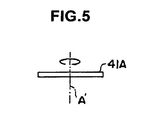
- the rotating axis A of the line sensor 41 is set at one end of the line sensor 41.
- a rotating axis A' may be set at the center of the line sensor 41A in the length direction (at the center in the direction in which the light receiving element group is arranged). In this case, it is possible to acquire image data of the entire region of an omnidirectional image by rotating the line sensor 41A by 180 degrees to perform scanning.
- light is used to perform both the supply of power to the line sensor and the transmission of signals from the line sensor.
- the supply of power and the transmission of signals may be performed by a wireless system.
- a wireless system may be used for the supply of power to the line sensor, and light may be used for the transmission of signals from the line sensor.
- light may be used for the supply of power to the line sensor, and the wireless system may be used for the transmission of signals from the line sensor.
- the supply of power to the line sensor or the transmission of signals from the line sensor may be performed by electromagnetic induction using an electromagnetic coil.
- the line sensor 41 includes a group of light receiving elements arranged in a line.
- a line sensor (not shown) including a plurality of rows of light receiving element groups arranged in straight lines in parallel to each other may be used.
Landscapes
- Engineering & Computer Science (AREA)
- Multimedia (AREA)
- Signal Processing (AREA)
- Studio Devices (AREA)
- Stereoscopic And Panoramic Photography (AREA)
- Image Input (AREA)
Claims (4)
- Omnidirektionale Bildgebungsvorrichtung, umfassend:eine Bildaufnahmeoptik (20, 20A), die ein omnidirektionales Bild mit Objektinformation in allen darin angeordneten radialen Richtungen erzeugt;eine Bildgebungseinheit (4), die Bilddaten des von der Abbildungsoptik erzeugten omnidirektionalen Bildes umfasst; undeine Panoramabild-Erzeugungseinheit (6), die ein Panoramabild mit der Objektinformation in sämtlichen Richtungen in paralleler Anordnung erzeugt auf der Grundlage der von der Bildgebungseinheit (4) erfassten Bilddaten des omnidirektionalen Bildes,wobei die Bildgebungseinheit (4) einen Zeilensensor (41) enthält, der eine Gruppe von Lichtempfangselementen besitzt, die in eine Richtung orthogonal zu einer vorbestimmten Drehachse angeordnet sind und um die vorbestimmte Drehachse (Z1; Z2) zum Ausführen einer Abtastung drehen können,wobei die Bildgebungseinheit (40) den Zeilensensor (41) dreht, um eine Abtastung durchzuführen und dadurch sequentiell die Bilddaten des omnidirektionalen Bildes in allen Richtungen zu erfassen, unddie Panoramabild-Erzeugungseinheit (60) das Panoramabild auf der Grundlage der sequentiell in sämtlichen Richtungen durch die Bildgebungseinheit erfassten Bilddaten des omnidirektionalen Bildes erzeugt,dadurch gekennzeichnet, dass die Bildgebungseinheit (40) enthält:eine Drehwelle (43a), die von einem Motor (43) angetrieben wird und einen hohlen Abschnitt aufweist, in welchem ein Lichtweg gebildet ist;einen Drehabschnitt (44), der an einer Seite der Drehwelle (43) befestigt ist;einen festen Abschnitt (42), der von einem festen Abschnitt am anderen Ende der Drehwelle (43) gehalten wird und den Motor (43) stützt;
dass der Drehabschnitt trägt:einen Zeilensensor (41), der eine Gruppe von Lichtempfangselementen enthält, die in eine Richtung orthogonal zu einer Drehachse angeordnet sind, und der sich durch eine Drehung der Drehwelle (43a) zum Ausführen einer Abtastung um die Drehachse dreht;eine elektrooptische Wandlereinheit (50), die von dem Zeilensensor gelesene Bilddaten umwandelt in ein Lichtsignal einer ersten Wellenlänge und das Lichtsignal ausgibt;ein erstes dicroitisches Prisma (50), welches das Lichtsignal abtrennt vom Leistungszufuhrlicht mit einer zweiten, von der ersten Wellenlänge verschiedenen Wellenlänge, durch Reflexion und Transmission, wobei das erste dicroitische Prisma (50) Wellenlängen-Selektivität besitzt;ein erstes reflektierendes Prisma (49), welches das von dem ersten dicroitischen Prisma (50) abgeteilte Lichtsignal in einen ersten Lichtweg einleitet und das zur Leistungszufuhr dienende Licht aus einem zweiten Lichtweg in das erste dicroitische Prisma (50) leitet, wobei der erste Lichtweg einen Weg auf einer Mitte-Drehachse der Drehwelle von einem Ende der Drehwelle zu deren anderen Ende ist, der zweite Lichtweg ein Weg auf der Mittelachse von dem anderen Ende der Drehwelle (43a) zu deren einem Ende ist;eine photoelektrische Wandler-Leistungszufuhreinheit (51), die das zur Leistungszufuhr dienende, von dem ersten dicroitischen Prisma abgeteilte Licht empfängt, um das der Leistungszufuhr dienende Licht umzuwandeln in Leistung, und diese Leistung dem Zeilensensor (41) und der elektrooptischen Wandlereinheit (54) zuführt; unddass der feste Abschnitt der Bildgebungseinheit enthält:eine Laserlichtquelle (46), die das zur Leistungszufuhr dienende Licht mit der zweiten Wellenlänge ausgibt;
ein zweites dicroitisches Prisma (47), welches das Lichtsignal mit der ersten Wellenlänge von dem der Leistungszufuhr dienenden Licht durch Reflexion und Transmission abtrennt, wobei das zweite dicroitische Prisma Wellenlängenselektivität besitzt;
ein zweites reflektierendes Prisma (48), welches das zur Leistungszufuhr dienende, von dem zweiten dicroitischen Prisma (47) abgetrennte Licht in den zweiten Lichtweg leitet und das Lichtsignal aus dem ersten Lichtweg in das zweite dicroitische Prisma (47) leitet;
eine photoelektrische Wandlereinheit (55), die das von dem zweiten dicroitischen Prisma (47) abgeteilte Lichtsignal empfängt und das Lichtsignal in das omnidirektionale Bild umwandelt. - Omnidirektionale Bildgebungsvorrichtung nach Anspruch 1, bei der die Abbildungsoptik (20) ein Weitwinkelobjektiv (21) enthält, welches in sämtliche Richtungen einfallende Strahlen bricht und die gebrochenen Strahlen fokussiert.
- Omnidirektionale Bildgebungsvorrichtung nach Anspruch 1, bei der die Abbildungsoptik (20A) einen gekrümmten Spiegel (22) enthält, der in sämtliche Richtungen einfallende Strahlen reflektiert und die reflektierten Strahlen fokussiert.
- Omnidirektionale Bildgebungsvorrichtung nach einem der Ansprüche 1 bis 3, bei der der Zeilensensor (41) eine vorbestimmte Drehachse (A) aufweist, die in seiner Mitte in einer Richtung vorgesehen ist, in der die Gruppe von Lichtempfangselementen angeordnet ist.
Applications Claiming Priority (1)
| Application Number | Priority Date | Filing Date | Title |
|---|---|---|---|
| JP2008156953A JP4787292B2 (ja) | 2008-06-16 | 2008-06-16 | 全方位撮像装置 |
Publications (3)
| Publication Number | Publication Date |
|---|---|
| EP2136551A2 EP2136551A2 (de) | 2009-12-23 |
| EP2136551A3 EP2136551A3 (de) | 2010-02-03 |
| EP2136551B1 true EP2136551B1 (de) | 2012-01-25 |
Family
ID=40903485
Family Applications (1)
| Application Number | Title | Priority Date | Filing Date |
|---|---|---|---|
| EP09007795A Not-in-force EP2136551B1 (de) | 2008-06-16 | 2009-06-12 | Omnidirektionale Bildgebungsvorrichtung |
Country Status (4)
| Country | Link |
|---|---|
| US (1) | US20090309957A1 (de) |
| EP (1) | EP2136551B1 (de) |
| JP (1) | JP4787292B2 (de) |
| AT (1) | ATE543331T1 (de) |
Families Citing this family (10)
| Publication number | Priority date | Publication date | Assignee | Title |
|---|---|---|---|---|
| JP5533048B2 (ja) * | 2010-03-08 | 2014-06-25 | ソニー株式会社 | 撮像制御装置、撮像制御方法 |
| JP5536060B2 (ja) * | 2010-03-18 | 2014-07-02 | パナソニック株式会社 | 全方位画像処理装置および全方位画像処理方法 |
| CA2860779A1 (en) * | 2012-01-13 | 2013-07-18 | Logos Technologies Llc | Panoramic image scanning device using multiple rotating cameras and one scanning mirror with multiple surfaces |
| JP6065474B2 (ja) * | 2012-09-11 | 2017-01-25 | 株式会社リコー | 撮像制御装置、撮像制御方法およびプログラム |
| CN103973944A (zh) * | 2013-02-06 | 2014-08-06 | 深圳市振华微电子有限公司 | 半球型全景成像装置及方法 |
| JP6271917B2 (ja) * | 2013-09-06 | 2018-01-31 | キヤノン株式会社 | 画像記録装置及び撮像装置 |
| GB2529848B (en) * | 2014-09-03 | 2018-12-19 | Dyson Technology Ltd | A mobile robot |
| JP5843027B1 (ja) * | 2015-03-10 | 2016-01-13 | 株式会社リコー | 撮像装置、制御方法およびプログラム |
| KR101668815B1 (ko) * | 2016-02-15 | 2016-10-24 | 정은진 | 광시야각 렌즈 및 그 렌즈를 포함한 광시야각 카메라 |
| US10337987B2 (en) | 2017-06-16 | 2019-07-02 | Canon U.S.A. , Inc. | Radial-line scanning spectrometer with two-dimensional sensor |
Family Cites Families (14)
| Publication number | Priority date | Publication date | Assignee | Title |
|---|---|---|---|---|
| FR2569861B1 (fr) * | 1982-12-28 | 1990-01-26 | Thomson Csf | Dispositif de couplage optique a joint tournant |
| EP0149286A1 (de) * | 1984-01-06 | 1985-07-24 | Jerome Hal Lemelson | Verfahren und System zur Übertragung |
| JPS6478078A (en) * | 1987-09-18 | 1989-03-23 | Olympus Optical Co | Solid-state image pickup device |
| US6118474A (en) * | 1996-05-10 | 2000-09-12 | The Trustees Of Columbia University In The City Of New York | Omnidirectional imaging apparatus |
| JPH11252452A (ja) * | 1998-02-26 | 1999-09-17 | Toshiba Tec Corp | パノラマ撮像装置 |
| JP2001008232A (ja) * | 1999-06-25 | 2001-01-12 | Matsushita Electric Ind Co Ltd | 全方位映像出力方法と装置 |
| US7176960B1 (en) * | 1999-09-20 | 2007-02-13 | The Trustees Of Columbia University In The City Of New York | System and methods for generating spherical mosaic images |
| EP1413982A1 (de) * | 2001-05-25 | 2004-04-28 | Matsushita Electric Industrial Co., Ltd. | Weitwinkelbilderzeugungseinrichtung |
| JP3979522B2 (ja) * | 2002-02-21 | 2007-09-19 | シャープ株式会社 | カメラ装置及び監視システム |
| US8018489B2 (en) * | 2005-02-04 | 2011-09-13 | Mccutchen David | Surveillance system |
| US7402793B2 (en) * | 2005-02-28 | 2008-07-22 | Arachnid, Inc. | System and method for controlling and energizing a rotating object |
| JP2007243357A (ja) * | 2006-03-06 | 2007-09-20 | Victor Co Of Japan Ltd | 伝送装置 |
| JP2008028606A (ja) * | 2006-07-20 | 2008-02-07 | Opt Kk | パノラマ展開画像撮像装置およびパノラマ展開画像撮像システム |
| JP4451892B2 (ja) * | 2007-03-19 | 2010-04-14 | 株式会社リコー | 映像再生装置、映像再生方法、及び映像再生プログラム |
-
2008
- 2008-06-16 JP JP2008156953A patent/JP4787292B2/ja not_active Expired - Fee Related
-
2009
- 2009-06-12 EP EP09007795A patent/EP2136551B1/de not_active Not-in-force
- 2009-06-12 AT AT09007795T patent/ATE543331T1/de active
- 2009-06-15 US US12/484,926 patent/US20090309957A1/en not_active Abandoned
Also Published As
| Publication number | Publication date |
|---|---|
| JP2009303053A (ja) | 2009-12-24 |
| JP4787292B2 (ja) | 2011-10-05 |
| EP2136551A3 (de) | 2010-02-03 |
| EP2136551A2 (de) | 2009-12-23 |
| US20090309957A1 (en) | 2009-12-17 |
| ATE543331T1 (de) | 2012-02-15 |
Similar Documents
| Publication | Publication Date | Title |
|---|---|---|
| EP2136551B1 (de) | Omnidirektionale Bildgebungsvorrichtung | |
| EP3608717B1 (de) | Bildgebungsvorrichtungen mit breitem sichtfeld (fov) und fähigkeit zur aktiven foveation | |
| US8174612B1 (en) | Imaging device | |
| US6744569B2 (en) | Method and apparatus for omnidirectional three dimensional imaging | |
| US20080247061A1 (en) | Integrated Panoramic and Forward Optical Device, System and Method for Omnidirectional Signal Processing | |
| EP1172678A2 (de) | Rundumbeobachtungs-Sensor | |
| US6847497B2 (en) | Wide-angle imaging device | |
| EP0977068A2 (de) | Bildumkehrvorrichtung | |
| CN101414033A (zh) | 光纤线阵数码元、器件及其成像方法 | |
| US4516159A (en) | Elevation step scanner | |
| CN103197208A (zh) | 一种可进行视场扫描的双通道日盲紫外成像仪 | |
| CN109478011A (zh) | 用于全景成像的方法和装置 | |
| JPH01292919A (ja) | 光スリツプリング装置 | |
| CN112769480B (zh) | 一种超大视场角的空间激光至光纤耦合装置及应用方法 | |
| CN214627103U (zh) | 摄像组件和电子设备 | |
| CN112198752B (zh) | 成像装置和电子设备 | |
| CN112040097B (zh) | 一种视场拼接的大幅面相机系统 | |
| JP3649621B2 (ja) | 光通信装置 | |
| CN201302613Y (zh) | 光纤线阵数码元、器件 | |
| JP4462134B2 (ja) | 光信号伝送システム | |
| JPH09218101A (ja) | 熱撮像器の基準システム | |
| US20100027090A1 (en) | Scanning apparatus | |
| KR100263925B1 (ko) | 광학계이용영상획득장치 | |
| WO2005096064A2 (en) | Scanning apparatus | |
| CN117706652A (zh) | 基于太赫兹信号的图像采集装置、图像生成系统及方法 |
Legal Events
| Date | Code | Title | Description |
|---|---|---|---|
| PUAI | Public reference made under article 153(3) epc to a published international application that has entered the european phase |
Free format text: ORIGINAL CODE: 0009012 |
|
| 17P | Request for examination filed |
Effective date: 20090612 |
|
| AK | Designated contracting states |
Kind code of ref document: A2 Designated state(s): AT BE BG CH CY CZ DE DK EE ES FI FR GB GR HR HU IE IS IT LI LT LU LV MC MK MT NL NO PL PT RO SE SI SK TR |
|
| PUAL | Search report despatched |
Free format text: ORIGINAL CODE: 0009013 |
|
| AK | Designated contracting states |
Kind code of ref document: A3 Designated state(s): AT BE BG CH CY CZ DE DK EE ES FI FR GB GR HR HU IE IS IT LI LT LU LV MC MK MT NL NO PL PT RO SE SI SK TR |
|
| AX | Request for extension of the european patent |
Extension state: AL BA RS |
|
| RIC1 | Information provided on ipc code assigned before grant |
Ipc: H04B 10/00 20060101ALI20091229BHEP Ipc: H04N 5/232 20060101AFI20090817BHEP |
|
| 17Q | First examination report despatched |
Effective date: 20100928 |
|
| GRAP | Despatch of communication of intention to grant a patent |
Free format text: ORIGINAL CODE: EPIDOSNIGR1 |
|
| RIN1 | Information on inventor provided before grant (corrected) |
Inventor name: MOCHITATE, SEIJI Inventor name: GE, ZONGTAO |
|
| RAP1 | Party data changed (applicant data changed or rights of an application transferred) |
Owner name: FUJIFILM CORPORATION |
|
| GRAS | Grant fee paid |
Free format text: ORIGINAL CODE: EPIDOSNIGR3 |
|
| GRAA | (expected) grant |
Free format text: ORIGINAL CODE: 0009210 |
|
| AK | Designated contracting states |
Kind code of ref document: B1 Designated state(s): AT BE BG CH CY CZ DE DK EE ES FI FR GB GR HR HU IE IS IT LI LT LU LV MC MK MT NL NO PL PT RO SE SI SK TR |
|
| REG | Reference to a national code |
Ref country code: GB Ref legal event code: FG4D |
|
| REG | Reference to a national code |
Ref country code: CH Ref legal event code: EP |
|
| REG | Reference to a national code |
Ref country code: AT Ref legal event code: REF Ref document number: 543331 Country of ref document: AT Kind code of ref document: T Effective date: 20120215 |
|
| REG | Reference to a national code |
Ref country code: IE Ref legal event code: FG4D |
|
| REG | Reference to a national code |
Ref country code: DE Ref legal event code: R096 Ref document number: 602009004845 Country of ref document: DE Effective date: 20120322 |
|
| REG | Reference to a national code |
Ref country code: NL Ref legal event code: VDEP Effective date: 20120125 |
|
| LTIE | Lt: invalidation of european patent or patent extension |
Effective date: 20120125 |
|
| PG25 | Lapsed in a contracting state [announced via postgrant information from national office to epo] |
Ref country code: NO Free format text: LAPSE BECAUSE OF FAILURE TO SUBMIT A TRANSLATION OF THE DESCRIPTION OR TO PAY THE FEE WITHIN THE PRESCRIBED TIME-LIMIT Effective date: 20120425 Ref country code: BE Free format text: LAPSE BECAUSE OF FAILURE TO SUBMIT A TRANSLATION OF THE DESCRIPTION OR TO PAY THE FEE WITHIN THE PRESCRIBED TIME-LIMIT Effective date: 20120125 Ref country code: LT Free format text: LAPSE BECAUSE OF FAILURE TO SUBMIT A TRANSLATION OF THE DESCRIPTION OR TO PAY THE FEE WITHIN THE PRESCRIBED TIME-LIMIT Effective date: 20120125 Ref country code: IS Free format text: LAPSE BECAUSE OF FAILURE TO SUBMIT A TRANSLATION OF THE DESCRIPTION OR TO PAY THE FEE WITHIN THE PRESCRIBED TIME-LIMIT Effective date: 20120525 Ref country code: BG Free format text: LAPSE BECAUSE OF FAILURE TO SUBMIT A TRANSLATION OF THE DESCRIPTION OR TO PAY THE FEE WITHIN THE PRESCRIBED TIME-LIMIT Effective date: 20120425 Ref country code: NL Free format text: LAPSE BECAUSE OF FAILURE TO SUBMIT A TRANSLATION OF THE DESCRIPTION OR TO PAY THE FEE WITHIN THE PRESCRIBED TIME-LIMIT Effective date: 20120125 Ref country code: HR Free format text: LAPSE BECAUSE OF FAILURE TO SUBMIT A TRANSLATION OF THE DESCRIPTION OR TO PAY THE FEE WITHIN THE PRESCRIBED TIME-LIMIT Effective date: 20120125 |
|
| PG25 | Lapsed in a contracting state [announced via postgrant information from national office to epo] |
Ref country code: PL Free format text: LAPSE BECAUSE OF FAILURE TO SUBMIT A TRANSLATION OF THE DESCRIPTION OR TO PAY THE FEE WITHIN THE PRESCRIBED TIME-LIMIT Effective date: 20120125 Ref country code: GR Free format text: LAPSE BECAUSE OF FAILURE TO SUBMIT A TRANSLATION OF THE DESCRIPTION OR TO PAY THE FEE WITHIN THE PRESCRIBED TIME-LIMIT Effective date: 20120426 Ref country code: LV Free format text: LAPSE BECAUSE OF FAILURE TO SUBMIT A TRANSLATION OF THE DESCRIPTION OR TO PAY THE FEE WITHIN THE PRESCRIBED TIME-LIMIT Effective date: 20120125 Ref country code: FI Free format text: LAPSE BECAUSE OF FAILURE TO SUBMIT A TRANSLATION OF THE DESCRIPTION OR TO PAY THE FEE WITHIN THE PRESCRIBED TIME-LIMIT Effective date: 20120125 Ref country code: PT Free format text: LAPSE BECAUSE OF FAILURE TO SUBMIT A TRANSLATION OF THE DESCRIPTION OR TO PAY THE FEE WITHIN THE PRESCRIBED TIME-LIMIT Effective date: 20120525 |
|
| REG | Reference to a national code |
Ref country code: AT Ref legal event code: MK05 Ref document number: 543331 Country of ref document: AT Kind code of ref document: T Effective date: 20120125 |
|
| PG25 | Lapsed in a contracting state [announced via postgrant information from national office to epo] |
Ref country code: CY Free format text: LAPSE BECAUSE OF FAILURE TO SUBMIT A TRANSLATION OF THE DESCRIPTION OR TO PAY THE FEE WITHIN THE PRESCRIBED TIME-LIMIT Effective date: 20120125 |
|
| PG25 | Lapsed in a contracting state [announced via postgrant information from national office to epo] |
Ref country code: DK Free format text: LAPSE BECAUSE OF FAILURE TO SUBMIT A TRANSLATION OF THE DESCRIPTION OR TO PAY THE FEE WITHIN THE PRESCRIBED TIME-LIMIT Effective date: 20120125 Ref country code: SE Free format text: LAPSE BECAUSE OF FAILURE TO SUBMIT A TRANSLATION OF THE DESCRIPTION OR TO PAY THE FEE WITHIN THE PRESCRIBED TIME-LIMIT Effective date: 20120125 Ref country code: RO Free format text: LAPSE BECAUSE OF FAILURE TO SUBMIT A TRANSLATION OF THE DESCRIPTION OR TO PAY THE FEE WITHIN THE PRESCRIBED TIME-LIMIT Effective date: 20120125 Ref country code: CZ Free format text: LAPSE BECAUSE OF FAILURE TO SUBMIT A TRANSLATION OF THE DESCRIPTION OR TO PAY THE FEE WITHIN THE PRESCRIBED TIME-LIMIT Effective date: 20120125 Ref country code: EE Free format text: LAPSE BECAUSE OF FAILURE TO SUBMIT A TRANSLATION OF THE DESCRIPTION OR TO PAY THE FEE WITHIN THE PRESCRIBED TIME-LIMIT Effective date: 20120125 Ref country code: SI Free format text: LAPSE BECAUSE OF FAILURE TO SUBMIT A TRANSLATION OF THE DESCRIPTION OR TO PAY THE FEE WITHIN THE PRESCRIBED TIME-LIMIT Effective date: 20120125 |
|
| PG25 | Lapsed in a contracting state [announced via postgrant information from national office to epo] |
Ref country code: SK Free format text: LAPSE BECAUSE OF FAILURE TO SUBMIT A TRANSLATION OF THE DESCRIPTION OR TO PAY THE FEE WITHIN THE PRESCRIBED TIME-LIMIT Effective date: 20120125 Ref country code: IT Free format text: LAPSE BECAUSE OF FAILURE TO SUBMIT A TRANSLATION OF THE DESCRIPTION OR TO PAY THE FEE WITHIN THE PRESCRIBED TIME-LIMIT Effective date: 20120125 |
|
| PLBE | No opposition filed within time limit |
Free format text: ORIGINAL CODE: 0009261 |
|
| STAA | Information on the status of an ep patent application or granted ep patent |
Free format text: STATUS: NO OPPOSITION FILED WITHIN TIME LIMIT |
|
| 26N | No opposition filed |
Effective date: 20121026 |
|
| PG25 | Lapsed in a contracting state [announced via postgrant information from national office to epo] |
Ref country code: AT Free format text: LAPSE BECAUSE OF FAILURE TO SUBMIT A TRANSLATION OF THE DESCRIPTION OR TO PAY THE FEE WITHIN THE PRESCRIBED TIME-LIMIT Effective date: 20120125 Ref country code: MC Free format text: LAPSE BECAUSE OF NON-PAYMENT OF DUE FEES Effective date: 20120630 |
|
| REG | Reference to a national code |
Ref country code: DE Ref legal event code: R097 Ref document number: 602009004845 Country of ref document: DE Effective date: 20121026 |
|
| PG25 | Lapsed in a contracting state [announced via postgrant information from national office to epo] |
Ref country code: MK Free format text: LAPSE BECAUSE OF FAILURE TO SUBMIT A TRANSLATION OF THE DESCRIPTION OR TO PAY THE FEE WITHIN THE PRESCRIBED TIME-LIMIT Effective date: 20120125 |
|
| REG | Reference to a national code |
Ref country code: IE Ref legal event code: MM4A |
|
| REG | Reference to a national code |
Ref country code: FR Ref legal event code: ST Effective date: 20130228 |
|
| PG25 | Lapsed in a contracting state [announced via postgrant information from national office to epo] |
Ref country code: IE Free format text: LAPSE BECAUSE OF NON-PAYMENT OF DUE FEES Effective date: 20120612 Ref country code: FR Free format text: LAPSE BECAUSE OF NON-PAYMENT OF DUE FEES Effective date: 20120702 Ref country code: ES Free format text: LAPSE BECAUSE OF FAILURE TO SUBMIT A TRANSLATION OF THE DESCRIPTION OR TO PAY THE FEE WITHIN THE PRESCRIBED TIME-LIMIT Effective date: 20120506 |
|
| PG25 | Lapsed in a contracting state [announced via postgrant information from national office to epo] |
Ref country code: MT Free format text: LAPSE BECAUSE OF FAILURE TO SUBMIT A TRANSLATION OF THE DESCRIPTION OR TO PAY THE FEE WITHIN THE PRESCRIBED TIME-LIMIT Effective date: 20120125 |
|
| PGFP | Annual fee paid to national office [announced via postgrant information from national office to epo] |
Ref country code: DE Payment date: 20130605 Year of fee payment: 5 |
|
| REG | Reference to a national code |
Ref country code: CH Ref legal event code: PL |
|
| GBPC | Gb: european patent ceased through non-payment of renewal fee |
Effective date: 20130612 |
|
| PG25 | Lapsed in a contracting state [announced via postgrant information from national office to epo] |
Ref country code: TR Free format text: LAPSE BECAUSE OF FAILURE TO SUBMIT A TRANSLATION OF THE DESCRIPTION OR TO PAY THE FEE WITHIN THE PRESCRIBED TIME-LIMIT Effective date: 20120125 Ref country code: LI Free format text: LAPSE BECAUSE OF NON-PAYMENT OF DUE FEES Effective date: 20130630 Ref country code: GB Free format text: LAPSE BECAUSE OF NON-PAYMENT OF DUE FEES Effective date: 20130612 Ref country code: CH Free format text: LAPSE BECAUSE OF NON-PAYMENT OF DUE FEES Effective date: 20130630 |
|
| PG25 | Lapsed in a contracting state [announced via postgrant information from national office to epo] |
Ref country code: LU Free format text: LAPSE BECAUSE OF NON-PAYMENT OF DUE FEES Effective date: 20120612 |
|
| PG25 | Lapsed in a contracting state [announced via postgrant information from national office to epo] |
Ref country code: HU Free format text: LAPSE BECAUSE OF FAILURE TO SUBMIT A TRANSLATION OF THE DESCRIPTION OR TO PAY THE FEE WITHIN THE PRESCRIBED TIME-LIMIT Effective date: 20090612 |
|
| REG | Reference to a national code |
Ref country code: DE Ref legal event code: R119 Ref document number: 602009004845 Country of ref document: DE |
|
| REG | Reference to a national code |
Ref country code: DE Ref legal event code: R119 Ref document number: 602009004845 Country of ref document: DE Effective date: 20150101 |
|
| PG25 | Lapsed in a contracting state [announced via postgrant information from national office to epo] |
Ref country code: DE Free format text: LAPSE BECAUSE OF NON-PAYMENT OF DUE FEES Effective date: 20150101 |