EP2136484A1 - Visible light transmitter, visible light receiver, visible light communication system, and visible light communication method - Google Patents
Visible light transmitter, visible light receiver, visible light communication system, and visible light communication method Download PDFInfo
- Publication number
- EP2136484A1 EP2136484A1 EP07860136A EP07860136A EP2136484A1 EP 2136484 A1 EP2136484 A1 EP 2136484A1 EP 07860136 A EP07860136 A EP 07860136A EP 07860136 A EP07860136 A EP 07860136A EP 2136484 A1 EP2136484 A1 EP 2136484A1
- Authority
- EP
- European Patent Office
- Prior art keywords
- light
- chromaticity coordinates
- value
- visible light
- coordinates value
- Prior art date
- Legal status (The legal status is an assumption and is not a legal conclusion. Google has not performed a legal analysis and makes no representation as to the accuracy of the status listed.)
- Granted
Links
- 238000004891 communication Methods 0.000 title claims abstract description 45
- 238000000034 method Methods 0.000 title claims description 17
- 230000005540 biological transmission Effects 0.000 claims abstract description 108
- 230000003595 spectral effect Effects 0.000 claims abstract description 27
- 239000003086 colorant Substances 0.000 claims abstract description 22
- 238000013507 mapping Methods 0.000 claims abstract description 17
- 239000011159 matrix material Substances 0.000 claims description 31
- 230000000694 effects Effects 0.000 description 15
- 230000035945 sensitivity Effects 0.000 description 15
- 238000001228 spectrum Methods 0.000 description 11
- 230000008859 change Effects 0.000 description 8
- 238000006243 chemical reaction Methods 0.000 description 8
- 230000007423 decrease Effects 0.000 description 8
- 238000000295 emission spectrum Methods 0.000 description 8
- 230000003247 decreasing effect Effects 0.000 description 5
- 238000009826 distribution Methods 0.000 description 5
- 230000003287 optical effect Effects 0.000 description 5
- 238000005516 engineering process Methods 0.000 description 4
- 230000004044 response Effects 0.000 description 4
- 206010034960 Photophobia Diseases 0.000 description 3
- 208000013469 light sensitivity Diseases 0.000 description 3
- 230000000638 stimulation Effects 0.000 description 3
- 238000004737 colorimetric analysis Methods 0.000 description 2
- 230000001419 dependent effect Effects 0.000 description 2
- 238000005401 electroluminescence Methods 0.000 description 2
- 239000004065 semiconductor Substances 0.000 description 2
- 230000000007 visual effect Effects 0.000 description 2
- 230000002238 attenuated effect Effects 0.000 description 1
- 238000012937 correction Methods 0.000 description 1
- 238000000354 decomposition reaction Methods 0.000 description 1
- 238000001514 detection method Methods 0.000 description 1
- 238000011161 development Methods 0.000 description 1
- 238000010586 diagram Methods 0.000 description 1
- 239000000835 fiber Substances 0.000 description 1
- 235000019557 luminance Nutrition 0.000 description 1
- 238000012986 modification Methods 0.000 description 1
- 230000004048 modification Effects 0.000 description 1
- 239000013307 optical fiber Substances 0.000 description 1
- 230000035755 proliferation Effects 0.000 description 1
- 238000000926 separation method Methods 0.000 description 1
- 238000004904 shortening Methods 0.000 description 1
- 230000001360 synchronised effect Effects 0.000 description 1
- 230000007704 transition Effects 0.000 description 1
Images


Classifications
-
- H—ELECTRICITY
- H04—ELECTRIC COMMUNICATION TECHNIQUE
- H04B—TRANSMISSION
- H04B10/00—Transmission systems employing electromagnetic waves other than radio-waves, e.g. infrared, visible or ultraviolet light, or employing corpuscular radiation, e.g. quantum communication
- H04B10/11—Arrangements specific to free-space transmission, i.e. transmission through air or vacuum
- H04B10/114—Indoor or close-range type systems
- H04B10/116—Visible light communication
-
- H—ELECTRICITY
- H04—ELECTRIC COMMUNICATION TECHNIQUE
- H04B—TRANSMISSION
- H04B10/00—Transmission systems employing electromagnetic waves other than radio-waves, e.g. infrared, visible or ultraviolet light, or employing corpuscular radiation, e.g. quantum communication
- H04B10/50—Transmitters
-
- H—ELECTRICITY
- H04—ELECTRIC COMMUNICATION TECHNIQUE
- H04B—TRANSMISSION
- H04B10/00—Transmission systems employing electromagnetic waves other than radio-waves, e.g. infrared, visible or ultraviolet light, or employing corpuscular radiation, e.g. quantum communication
- H04B10/60—Receivers
-
- H—ELECTRICITY
- H04—ELECTRIC COMMUNICATION TECHNIQUE
- H04N—PICTORIAL COMMUNICATION, e.g. TELEVISION
- H04N11/00—Colour television systems
- H04N11/04—Colour television systems using pulse code modulation
-
- H—ELECTRICITY
- H04—ELECTRIC COMMUNICATION TECHNIQUE
- H04N—PICTORIAL COMMUNICATION, e.g. TELEVISION
- H04N7/00—Television systems
- H04N7/22—Adaptations for optical transmission
-
- H—ELECTRICITY
- H04—ELECTRIC COMMUNICATION TECHNIQUE
- H04N—PICTORIAL COMMUNICATION, e.g. TELEVISION
- H04N9/00—Details of colour television systems
- H04N9/64—Circuits for processing colour signals
Definitions
- the present invention relates to a visible light transmission apparatus, a visible light reception apparatus, a visible light communication system, and a visible light communication method.
- LEDs Light Emitting Diodes
- LEDs are most promising for light emission in high-speed optical data transmission in terms of influence on the human body and medical equipment
- other semiconductor light emitting devices are also available, inclusive of Laser Diodes (LDs) or Super Luminescent Diodes (SLDs) that offer a faster response performance.
- LDs Laser Diodes
- SLDs Super Luminescent Diodes
- data rate is dependent on the response speed of a light emitting device in optical communication.
- a technique for transmitting a large amount of data stably in one signal of light emission of a light emitting device is needed.
- Patent Document 1 discloses a structure for adjusting a control voltage to change the intensity of light emitted from a light source according to a frequency-multiplexed signal. With the use of this structure, it is possible to change the light intensity of a light source or transmit multiplexed data under on/off control. Compared to non-multiplexing, a higher data rate can be achieved.
- Patent Document 2 discloses a structure for transmitting different data by controlling light emission of a plurality of light sources having different spectrums. To be more specific, Patent Document 2 discloses a structure for transmitting data by mapping digital values (1, 0) to phase changes at a transition timing of a Pulse Width Modulation (PWM) signal.
- PWM Pulse Width Modulation
- the transmission technique of Patent Document 1 increases a transmission error rate due to a decrease in light intensity on a transmission path because multiplexed data is transmitted by modulating a light intensity.
- a light source as a transmission apparatus is a lighting device, its light intensity is decreased due to effects of shielding. Consequently, an increased transmission error rate decreases a data rate.
- the transmission technique of Patent Document 1 is implemented, it is not easy to increase a data rate up to the response limit of the light source.
- an object of the present invention is to provide a visible light transmission apparatus, a visible light reception apparatus, a visible light communication system, and a visible light communication method, for enabling transmission of data modulated to a multiple-value number including as many values as or values more than number of light sources and at the same time, suppressing an increase in a transmission error rate, caused by a decrease in light intensity on a transmission path.
- a visible light communication system comprising a transmission apparatus and a reception apparatus that conduct visible light communication.
- the transmission apparatus includes a plurality of light emitters for emitting light in different colors, a chromaticity coordinates calculator for mapping a digital value to a chromaticity coordinates value, and a light intensity controller for controlling a light intensity of each of the light emitters based on the chromaticity coordinates value corresponding to the digital value.
- the reception apparatus includes a plurality of light receivers having different spectral characteristics, a chromaticity coordinates calculator for calculating a chromaticity coordinates value according to a received light intensity detected by each of the light receivers, and a demodulator for demodulating the digital value from the chromaticity coordinates value.
- a visible light transmission apparatus including a plurality of light emitters for emitting light in different colors, a chromaticity coordinates calculator for mapping a digital value to a chromaticity coordinates value, and a light intensity controller for controlling a light intensity of each of the light emitters based on the chromaticity coordinates value corresponding to the digital value
- the plurality of light emitters may be grouped into a plurality of light emitter groups each group having a plurality of light emitters.
- the light intensity controller may control the plurality of light emitters to emit light periodically with light intensities corresponding to a predetermined chromaticity coordinates value being a reference point.
- the light intensity controller may control part of the plurality of light emitters to emit light always with light intensities corresponding to a predetermined chromaticity coordinates value being a reference point.
- the chromaticity coordinates calculator may map a DC-free encoded transmission signal to the chromaticity coordinates value.
- the light intensity controller may control the light intensity of each of the light emitters so that a total light intensity ratio of the light emitters in one PWM period correspond to the chromaticity coordinates value corresponding to the digital value.
- a visible light reception apparatus for demodulating a digital value corresponding to a chromaticity coordinates value, including a plurality of light receivers having different spectral characteristics, a chromaticity coordinates calculator for calculating the chromaticity coordinates value according to a received light intensity detected by each of the light receivers, and a demodulator for demodulating the digital value from the chromaticity coordinates value.
- the visible light reception apparatus may further include a chromaticity coordinates corrector for calculating a vector having elements being the received light intensities detected by the light receivers for a linear matrix for calibrating color reproduction and compensating the received light intensities detected by the light receivers.
- the chromaticity coordinates corrector may calculate each coefficient of the linear matrix based on received light intensities of the light receivers detected from received light corresponding to a predetermined chromaticity coordinates value being a reference point and light intensities of the light receivers calculated from the predetermined chromaticity coordinates value being the reference point.
- the chromaticity coordinates calculator may calculate the chromaticity coordinates value based on a total received light intensity detected by each of the light receivers in one PWM period.
- a visible light communication method in a visible light communication system having a transmission apparatus with a plurality of light emitters for emitting light in different colors and a reception apparatus with a plurality of light receivers having different spectral characteristics, including mapping a digital value to a chromaticity coordinates value by the transmission apparatus, controlling a light intensity of each of the light emitters based on the chromaticity coordinates value corresponding to the digital value by the transmission apparatus, calculating a chromaticity coordinates value according to a received light intensity detected by each of the light receivers by the reception apparatus, and demodulating the digital value from the chromaticity coordinates value by the reception apparatus.
- a visible light transmission apparatus with a plurality of light emitters for emitting light in different colors, including mapping a digital value to a chromaticity coordinates value, and controlling a light intensity of each of the light emitters based on the chromaticity coordinates value corresponding to the digital value.
- a visible light communication method in a visible light reception apparatus having a plurality of light receivers having different spectral characteristics, for demodulating a digital value corresponding to a chromaticity coordinates value, including calculating the chromaticity coordinates value according to a received light intensity detected by each of the light receivers, and demodulating the digital value from the chromaticity coordinates value.
- a digital value can be mapped to a chromaticity coordinates value, for transmission. Therefore, the multi-value transmission increases a data rate. Also, since the data transmission is not affected by light intensity attenuation on a transmission path, a high data rate is realized stably.
- data modulated to a multiple-value number including values more than the number of light sources can be transmitted and, at the same time, an increase in a transmission error rate caused by a decreased light intensity on a transmission path can be suppressed.
- the visible light communication system 1000 includes a structure for mapping a multiplexed digital value to a chromaticity coordinates value in a predetermined color system, a structure for controlling a plurality of light emitters to emit light at a chromaticity indicated by the chromaticity coordinates value, a structure for detecting the chromaticity coordinates value according to the intensity ratio of light received at each chromaticity, and a structure for demodulating an original digital value from the chromaticity coordinates. This will be described in more detail with reference to the drawings.
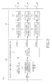
- FIG. 1 illustrates the configuration of the visible light communication system 1000 according to the embodiment of the present invention.
- the visible light communication system 1000 mainly includes a visible light transmission apparatus 100 and a visible light reception apparatus 200.
- the visible light transmission apparatus 100 mainly includes a plurality of light emitters 110 and a multiple-value modulation/emission controller 120.
- the visible light reception apparatus 200 mainly includes a plurality of light receivers 210 and a chromaticity detector/demodulator 220.
- the visible light transmission apparatus 100 may include, for example, a serial/parallel converter for converting digital values to parallel values on a bit basis and multiplexing the parallel values.
- the visible light reception apparatus 200 may include, for example, a parallel/serial converter for converting a plurality of bits to a serial digital value.
- the multi-value modulation/emission controller 120 multiplexes input digital values and maps the multiplexed digital value to a chromaticity coordinates value in a predetermined color system.
- a plurality of chromaticity points are placed in the color system according to a modulation multiplicity.
- the chromaticity points correspond accurately to signal points on a constellation used in multi-value communication of a propagation area.
- the chromaticity coordinates of the color system are obviously different from the signal points in that the chromaticity coordinates represent colors and chromas. Accordingly, the multiplicity of a digital value may be increased by as much as chroma representations.
- the multi-value modulation/emission controller 120 controls the light intensity of each of the light emitters 110. After setting the sum of light intensities of all the light emitters 110 to a predetermined value, the multi-value modulation/emission controller 120 may determine the light intensity ratio of each light emitter 110. That is, the multi-value modulation/emission controller 120 may apply the light intensity ratios of the light emitters 110 to the modulation signal corresponding to the multiplexed digital value. As a consequence, the problem of a decrease in a transmission error rate caused by a decrease in light intensity on a transmission path can be avoided.
- the plurality of light receivers 210 which have light reception sensitivities (spectral sensitivities) to different wavelengths, receive light corresponding to the chromaticity point and measure the intensity of the received light at each wavelength (color).
- the chromaticity detector/demodulator 220 calculates three stimulation values from the digitally modulated light intensity of the received light at each wavelength and detects a chromaticity point using the stimulation values using a color matching function. Also, the chromaticity detector/demodulator 220 demodulates a digital value corresponding to the chromaticity coordinates value of the chromaticity point.
- the chromaticity detector/demodulator 220 demodulates the digital value based on the same color system as used in the multi-value modulation/emission controller 120. It is assumed that the chromaticity detector/demodulator 220 already has information about the positions of color points placed in the predetermined color system.
- the configuration of the visible light communication system 1000 has been described in brief. According to the configuration, for example, as illustrated in FIG. 1 , information about a chromaticity point corresponding to multi-value signals S2, S8 and S6 can be transmitted at the ratios of the intensities of light emitted from the light emitters 110. As a result, the multiplicity may be increased to or above the number of the light emitters 110 and the problem of a decrease in a transmission error rate caused by a decrease in light intensity on a transmission path may be avoided. With reference to FIGs. 2 and 3 , functional structures of the visible light transmission apparatus 100 and the visible light reception apparatus 200 will be described below in detail.
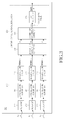
- FIG. 2 illustrates the functional structure of the visible light transmission apparatus 100 according to the embodiment of the present invention.
- the visible light transmission apparatus 100 mainly includes a chromaticity coordinates calculator 122, a light intensity controller 124, light source driving circuits 112, and light sources 114.
- the chromaticity coordinates calculator 122 and the light intensity controller 124 form the multi-value modulation/emission controller 120.
- the light source driving circuits 122 and the light sources 114 form the light emitters 110. While not shown, the visible light transmission apparatus 100 may further include the serial/parallel converter.
- the chromaticity coordinate calculator 122 maps a received digital value ⁇ to a chromaticity point. That is, the chromaticity coordinate calculator 122 maps each digital value to the chromaticity coordinates value of a chromaticity point corresponding to the digital value according to a layout of chromaticity points having predetermined multiple-value numbers.
- the chromaticity coordinate calculator 122 may use any of color systems including, for example, a Munsell color system and an Ostwald color system as well as a CIE color system (RGB, XYZ(Yxy), LxUxV, Lxaxb, etc) adopted by the Commission Internationale de l'Eclairage (CIE), as the color system having chromaticity points. This is because the visible light communication system 1000 according to the embodiment of the present invention can perform chromaticity detection by a scheme such as spectrophotometric colorimetry, as described later.
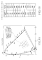
- FIG. 4 is a diagram illustrating a predetermined chromaticity point layout defined in a Yxy color system.
- a 2-degree visual field (a solid line) and a 10-degree visual field (a dotted line) are illustrated.
- a predetermined chromaticity point layout s is preliminarily set in the color system.
- Information about the type of the color system and the chromaticity point layout is shared between the visible light transmission apparatus 100 and the visible light reception apparatus 200 in advance, or notified by a predetermined method during data transmission.
- Chromaticity points S0 to S 15 are mapped to, for example, digital values illustrated in FIG. 4(B) .
- the chromaticity coordinate calculator 122 selects a chromaticity point corresponding to the input digital value ⁇ from among the chromaticity points S0 to S 15 and determines the chromaticity coordinates value (x, y) of the selected chromaticity point.
- the chromaticity coordinate calculator 122 selects the chromaticity point S7 and transmits the chromaticity coordinates value (x, y) of the chromaticity point to the light intensity controller 124.
- the multiplicity is expressed as 2 M (M is an integer)
- data transmission can be carried out by mapping an M-bit digital value to one chromaticity point.
- information about the chromaticity point layout of the color system illustrated in FIG. 4(A) may be tabulated as illustrated in FIG. 4(B) and shared between the visible light transmission apparatus 100 and the visible light reception apparatus 200.
- the light intensity controller 124 determines the light intensities of the light emitters 110 at respective wavelengths of light to emit light with the chromaticity indicated by the chromaticity coordinates value (x, y) determined by the chromaticity coordinate calculator 122. Especially, the light intensity controller 124 calculates a light intensity ratio for each wavelength to realize the chromaticity corresponding to the chromaticity coordinates value (x, y). For example, the light intensity controller 124 calculates a mixing ratio of Red (R), Green (G) and Blue (B) to realize the chromaticity corresponding to the chromaticity coordinates value (x, y) and calculates driving voltages for the light emitters 110 according to the light intensities of the colors.
- RGB Red
- G Green
- B Blue
- the light intensity controller 124 also determines the light intensity of each color so that the total light intensity of the light emitters 110 is a predetermined value and calculates a driving voltage corresponding to the light intensity of each color. This is because considering that chromaticity coordinate values are usually standardized as luminances, it is preferable to control the light intensities of the light emitters 110 according to the total light intensity.
- the light intensity controller 124 transmits a driving circuit control signal to each light source driving circuit 112 in order to emit light from each light source 114 at the driving voltage calculated for each color, as described later.
- the driving circuit control signal is used to control the light intensity of each light source 114.
- the light intensity controller 124 transmits three driving circuit control signals a, b and c to light source driving circuits (A), (B) and (C), respectively.
- the light intensity controller 124 may represent a chromaticity by controlling the total light intensity of the light sources 114 for a predetermined time. That is, the light intensity controller 124 multiplies the intensity of light that each light source 114 emits for a predetermined time, for each color and calculates a chromaticity coordinates value using the product value of each color as the received light intensity of each color. Then the light intensity controller 124 determines the driving voltage of each light source 114 as represented by the chromaticity coordinates value (x, y).
- the influence of the PWM control may be eliminated by mapping an accumulated light intensity value to a chromaticity coordinates value (x, y) according to a PWM period.
- the light intensity controller 124 controls the light intensity of each light source 114 according to a chromaticity corresponding to a predetermined chromaticity coordinates point (hereinafter, referred to as a reference point or a predetermined pattern) during initialization or periodically.
- a reference point or a predetermined pattern a predetermined chromaticity coordinates point
- the visible light reception apparatus 200 uses a linear matrix that calibrates the difference between the light emission spectrum of the transmitting side and the spectral sensitivity of the receiving side, for calibration of color reproduction.
- the visible light transmission apparatus 100 may transmit the reference signal for calibration of a linear matrix value by emitting light with a chromaticity corresponding to the reference point at a predetermined timing or periodically in order to cope with a change in the light emission spectrum of the transmitting side or a change in the spectral sensitivity of the receiving side.
- the light source circuits 112 control the light intensities of the later-described light sources 114 according to the driving circuit control signals received from the emission controller 124.
- a light source (A) driving circuit 112 connected to the light source (A) 114 receives the driving circuit control signal a and drives the light source (A) 114 to emit light at a driving voltage indicated by the driving circuit control signal a.
- a light source (B) driving circuit 112 and a light source (C) driving circuit 112 also drive the light source (B) 114 and the light source (C) 114 according to the driving circuit control signals b and c, respectively.
- the light sources 114 emit light according to the driving voltages supplied from the light source driving circuits 112.
- the light sources 114 are configured with semiconductor light emitting devices such as LEDs, LDs or SLDs, they may be configured with light emitting devices included in fluorescent lights, CRT displays, Plasma Display Panel (PDP) devices, Electro Luminescence (EL) displays, or LCDs.
- the visible light communication system 100 transmits data by mapping a digital value to chromaticity coordinates.
- the data transmission is different from data transmission based on wavelength modulation or the like and is performed to avoid influence on the spectral distribution of the light sources 114.
- peaks appear at the wavelengths of R, G and B.
- the spectrum of white light emitted by display devices described above has small peaks at the wavelengths of R, G and B and the spectrum is wide. If a structure for detecting a signal based on a spectrum shape or a signal strength is used, a difference from the spectrum shape is represented as a difference from demodulated data.
- the type of a device used as a light source needs to be limited.
- the signal may be received using the visible light reception apparatus 200 irrespective of the type of the light sources 114.
- light sources 114 having a variety of light emitting devices can be handled.
- the visible light transmission apparatus 100 has a plurality of light sources 114.
- the light sources 114 have their unique spectral distributions and may emit lights of different colors (La, Lb and Lc). Also, each light source 114 is not confined to a single-mode oscillator. It may be possible to group the plurality of light resources 114 into a plurality of groups each for emitting light of the same color and to control light intensity on a group basis.
- the light source driving circuits 112 are configured so as to supply driving voltages to the light sources 114 on a group basis or the light intensity controller 124 is configured so as to transmit the same driving circuit control signal to light source driving circuits 112 connected to the same group of light sources 114.
- the chromaticity of light may be adjusted by controlling the number of light emissions of the light sources 114 in each group through on/off control of all or part of the light sources 114 in the group.
- the chromaticity coordinates-based data transmission enables modulation of data to a multi-value number having as many values as or values more than the number of the light sources 114 in the visible light transmission apparatus 100, increases the amount of data transmittable in one pulse, and achieves higher-rate data transmission. Also, as information is carried at the light intensity ratio of each color, the resulting little influence of light intensity attenuation on the transmission path may lead to a decreased transmission error rate. Since data transmission is based on chromaticities, it is possible to achieve high speed by increasing the number of multiple values by the number of chromas included in the chromatcities and the type of the light sources 114 is not selected.
- FIG. 3 illustrates the functional configuration of the visible light reception apparatus 200 according to the embodiment of the present invention.
- the visible light reception apparatus 200 mainly includes filters 212, opto-electric converters 214, AD conversion circuits 216, a chromaticity coordinates corrector 222, a chromaticity coordinates value detector 224, and a demodulator 226.
- the filters 212, the opto-electric converters 214, and AD conversion circuits 216 form the light receivers 210.
- the chromaticity coordinates corrector 222, the chromaticity coordinates value detector 224, and the demodulator 226 form the chromaticity detector/demodulator 220.
- the filters 212 are optical filters having predetermined spectral sensitivity characteristics. To be more specific, the filters 212 are color filters for separating light of each color. When light is incident through the filters 212, the opto-electric converters 214 output power according to their received light intensities. Hence, the received light intensity of each color may be detected by combining the filters 212 and the opto-electric converters 214.
- the opto-electric converters 214 are configured with, for example, Photo Diodes (PDs) (pn-type PDs, pin-type PDs, or Avalanche Photo Diodes (APDs)) and output currents of amounts proportional to the received light intensities.
- PDs Photo Diodes
- APDs Avalanche Photo Diodes
- the opto-electric converters 214 may output signals according to the magnitudes of the output currents.
- color reproduction is calibrated using a linear matrix at a rear end in the visible light communication system 1000 according to the embodiment of the present invention, a chromaticity coordinates value can be detected even though the spectral sensitivity of the visible light reception apparatus 200 does not perfectly match to the spectral distribution of the visible light transmission apparatus 100.
- the AD conversion circuits 216 are A/D converters for converting analog signals to digital signals.
- the A/D conversion circuits 216 convert signals of respective colors (analog signals) received from the opto-electric converters 214 to digital signals. For instance, in the example of FIG. 3 , light incident on an opto-electric converter 214 through a filter (A') 212 is converted to an analog electric signal by opto-electric conversion, converted to a digital signal a' by an AD conversion circuit 216, and then provided to the chromaticity coordinates corrector 222. In the same manner, digital signals b' and c' corresponding to light incident through a filter (B') 212 and a filter (C') 212 are provided to the chromaticity coordinates corrector 222.
- the chromaticity coordinates corrector 222 calibrates color reproduction using a linear matrix scheme.
- the linear matrix scheme will be described briefly.
- a color calibration technology called a linear matrix scheme is used to calibrate color reproduction in a photographing device such as a digital camera or a video camera.
- This photographing device functions to determine components of a linear matrix by comparing the color reproduction of sample images (predetermined color patterns, etc.) captured under a predetermined condition (e.g. a constant lighting condition, etc.) with the color reproduction of sample images captured under an actual condition.
- the photographing device captures a sample image and determines matrix components that convert the RGB data (a received light intensity measured for each color) of the actually captured sample image to the RGB data of a preserved sample image.
- a linear matrix is applied to captured RGB data and the RGB data is converted to RGB data with no change in filter characteristics or received light sensitivity characteristics. Consequently, despite a change in filter characteristics or received light sensitivity characteristics, a linear matrix can be calibrated by use of a predetermined sample image. Therefore, an output result based on constant filter characteristics or received light sensitivity characteristics can be achieved.
- a decrease in the spectral sensitivity of the receiving side leads to an increase in a demodulation error rate, compared to a general wavelength multiplexing scheme in which light with a separated emission spectrum is received and demodulated.
- the spectral sensitivity of the receiving side is dependent on the spectral sensitivity of the opto-electric converters 214 and the color separation filters 212, for example, a change in the spectral sensitivities affects color reproduction.
- the linear matrix scheme used for a video camera or a digital video camera is adopted.
- reproduction-calibrated light intensities R', G' and B' of the respective colors are calculated by operating a predetermined matrix (a linear matrix) with the received light intensities of colors R, G and B, as by equation (1).
- the linear matrix scheme is used to make color reproduction approximate to an ideal color reproduction defined as a standard of a video signal.
- the elements of the matrix, a 11 ⁇ a 33 are coefficients determined according to the spectral sensitivities of the filters 212, the opto-electric converters 214, etc.
- Each coefficient of the linear matrix may be calculated using at least three sets of data with respect to the light intensities (R, G, B) and the post-calibration light intensities (R', G', B').
- the visible light transmission apparatus 100 mixes a transmission signal with a reference signal corresponding to a predetermined chromaticity coordinates value (a reference point) and transmits the mixed signal periodically or at a predetermined timing.
- the visible light reception apparatus 200 may calculate each coefficient of the linear matrix at the chromaticity coordinates corrector 222 after receiving the reference signal through the light receivers 210.
- the chromaticity coordinates corrector 222 may calculate each coefficient of the linear matrix using three or more sets of data by a least square method. According to the least square method, more reliable coefficients may be calculated.
- the chromaticity coordinates corrector 222 calculates equation (1) using the linear matrix acquired by the above method. That is, the chromaticity coordinates corrector 222 calibrates color reproduction so that the color coordinates of the transmitting side are identical to those of the receiving side. Consequently, the color coordinates of both the transmitting and receiving sides can be rendered identical through linear matrix conversion, even though the emission spectrum distribution of the visible light transmission apparatus 100 does not perfectly match to the spectral sensitivity of the visible light reception apparatus 200. For example, even though the color combination of the light sources 114 in the visible light transmission apparatus 100 is changed, a digital value corresponding to a chromaticity point can be decoded because the spacing between the chromaticity points S0 to S 15 and their relative position relationship are known.
- the chromaticity coordinates corrector 222 calculates the following equation (2).
- R ⁇ G ⁇ B ⁇ a 11 a 12 a 13 a 21 a 22 a 23 a 31 a 32 a 33 ⁇ R G B + R 0 G 0 B 0
- the chromaticity coordinates corrector 222 compensates digital signals a', b' and c' corresponding to the received light intensities of the respective colors by calculating equation (1) or equation (2) and provides the resulting compensated digital signals a, b and c to the chromaticity coordinates value detector 224.
- the chromaticity coordinates value detector 224 detects a chromaticity coordinates value (x, y) based on the digital signals a, b, and c compensated by the chromaticity coordinates corrector 222.
- the chromaticity coordinates value detector 224 detects the chromaticity coordinates value (x, y) based on the color system used in the chromaticity coordinate calculator 122 of the visible light transmission apparatus 100. For example, in case of the Yxy color system illustrated in FIG.
- the chromaticity coordinates value detector 224 calculates three stimulation values (X, Y, Z) from the digital signals (a, b, c) using a color matching function representing a spectral sensitivity corresponding to the human eye and derives the chromaticity coordinates value (x, y) from the calculation result. Meanwhile, the chromaticity coordinates value (x, y) may be derived from the digital signals (a, b, c) as done in spectrophotometric colorimetry. The chromaticity coordinates value detector 224 transmits the derived chromaticity coordinates value (x, y) to the demodulator 226.
- the chromaticity coordinates value detector 224 multiplies the digital signals (a, b, c) for the respective colors in one PWM period or over a predetermined time period and derives the chromaticity coordinates value (x, y) according to the resulting products (A, B, C).
- a light intensity perceivable to a human being can be adjusted by prolonging or shortening a light emission time through light intensity control by PWM driving of a light source.
- PWM driving of a light source since the chromaticity coordinates value (x, y) is measured using the light intensity multiplied over at least one PWM period, there is little influence of the PWM control.
- PWM periods should be synchronized among the light sources 114.
- the demodulator 226 demodulates the original digital value ⁇ based on the chromaticity coordinates value (x, y).
- the demodulator 226 may detect the digital value ⁇ corresponding to a chromaticity point at the chromaticity coordinates value (x, y) in the chromaticity point layout (refer to FIG. 4 ) of the color system used in the chromaticity coordinates calculator 122.
- the demodulator 226 preserves information about the chromaticity point layout.
- the chromaticity coordinates value corresponding to the received light intensities of the respective colors is calculated and the original digital value ⁇ is demodulated based on the chromaticity coordinates value (x, y). Therefore, an increase in a transmission error rate caused by attenuation of light intensity on a transmission path can be suppressed. Also, since color reproduction is calibrated using the linear matrix scheme, the original digital value ⁇ can be demodulated even though the emission spectrum of the transmitting side does not perfectly matches the light reception sensitivity of the receiving side. Now a detailed description will be made of effects that can be achieved from applying the visible light communication system 1000 according to the embodiment of the present invention.
- a structure for carrying out visible light communication by on/off control of three types of (R, G, B) light sources will be investigated.
- 1-bit data can be transmitted by each of R, G and B and thus 3-bit data can be transmitted by their combination. While octal numbers may be mapped to RGB combinations, for transmission, the transmission rate of data may not be increased because the number of bits of data transmittable at one time is less than that of light sources.
- the visible light communication system 1000 may offer special effects in that multiplexing of as many data as or data more than the number of light sources is possible, compared to the simple RGB on/off structure, because multiplexed digital values are mapped to multiple-value chromaticity points at chromaticity coordinates.
- a structure for mapping data to the absolute values of the intensities of light emitted from three types of (R, G, B) light sources and transmitting the absolute values will be considered.
- a structure for emitting light from light sources by controlling their light intensities in the transmitting side, and measuring the absolute values of received light intensities of R, G, and B and demodulating data corresponding to the received light intensities in the receiving side may be considered.
- This structure increases an error rate during demodulation as light intensity attenuates on a transmission path.
- the structure is applied to a lighting device or the like, the light intensity is readily attenuated due to the influence of shielding, etc. As a result, it is difficult to increase a data rate.
- the visible light communication system 1000 offers special effects in that a change in light intensity seldom affects an error rate during demodulation because a digital value is mapped to a chromaticity coordinates value, for transmission and thus the chromaticity coordinates value is detected according to a ratio (a relative value) of the received light intensity measured for each color, even though the light intensity is changed on the transmission path.
- a chrominance may be expressed as an angle of a color circle.
- a structure for defining data 1 as light emission in color corresponding to 10-degree clockwise movement of the color circle from red at the next timing after light emission in color at the position of red may be contemplated.
- the attenuation of light intensity on a transmission path does not affect a transmission error rate much as in the embodiment of the present invention.
- data 1 is mapped to the chrominance resulting from the 10-degree clockwise movement, successive transmission of data 1 changes color significantly in a particular direction.
- the color of a lighting device changes considerably and the types of available lighting devices are limited.
- the visible light communication system 1000 offers the special effects that successive transmission data are not followed, multiplexing using a predetermined color range is possible, and the colors of lighting devices are not changed much (the type and usage of a light source are not selected) because a digital value is modulated to a multiple-value number according to the chromaticity point layout of a color system. Compared to modulation to a chrominance, since as much multi-value modulation as chromas included in chromaticities is enabled, higher-rate data transmission is possible.
- the visible light communication system 1000 achieves the foregoing effects in view of the basic characteristic of mapping digital values to color coordinates, for transmission.
- the effects that the visible light communication system 1000 can achieve are not limited to the foregoing effects.
- an LCD or PDP that has a wider 3-color (R, G, B) light emission spectrum than an LED can be used as a light source.
- the chromaticity coordinates define color matching function-based responses, rather than they correspond to the spectrum of light. Therefore, the same chromaticity coordinates may result, despite different spectrums. For instance, white of a fluorescent light with a wide light emission spectrum and white having a strong peak in R, G, B (e.g. 623nm, 523nm, and 456nm) expressed as R, G, B of an LED are at the same chromaticity coordinates. Therefore, compared to a structure for identifying a signal by the shape of a spectrum, a special effect is achieved in that signal identification is possible irrespective of the spectral distribution of a light source.
- the colors of the light sources of the visible light transmission apparatus 100 are changed, data transmission is possible without changing the configuration of the visible light reception apparatus 200.
- This is based on a structure for transmitting a predetermined pattern at a chromaticity corresponding to a reference point and calibrating a linear matrix using the predetermined pattern.
- the chromaticity coordinates of the transmitting side can be matched to those of the receiving side based on the spacing between chromaticity points and the relative position relationship of the chromaticity points. Therefore, it is possible to detect a chromaticity coordinates point according to the received light intensity of each color that is converted by the linear matrix.
- a clock signal may be generated from transmitted data, many transmission rates may be handled.
- the effects of the visible light communication system 1000 according to the embodiment of the present invention have been described in detail.
- a relatively low-rate modulation is achieved in a typical lighting LED or the like.
- the use of the above-described configuration enables high-speed data transmission using a lighting device with a low modulation speed.
- the upper limit of multiplexing is determined according to the distance between chromaticities, noise, a mismatch width in light reception sensitivity, and an error correction capability, which also determine the upper limit of a data rate in the above configuration.
- the technology according to the embodiment of the present invention is applicable to an optical fiber transmission line as well as a wireless transmission line. Especially, it is possible to realize high-speed fiber optic communication using a multiplexed signal due to strong robustness against light intensity attenuation on a transmission path.
- a structure for spatially multiplexing a plurality of light sources is not described in the description of the embodiment of the present invention, it is possible to place a plurality of light source groups of the same configuration spatially (two-dimensionally), for multiplexing. In this case, data can be transmitted at as high a speed as spatial multiplexing.
- a structure for transmitting a reference signal from some light source group always enables calibration of a linear matrix using a signal corresponding to a reference point. Thus, even when light is incident from other light sources, the original state may be recovered fast.
- this structure it may be set whether to perform the linear matrix calibration always or at a predetermined timing in the receiving side.
- the spectrum decomposition of light may be carried out by using one spectral sensor or one detector, and one spectrum analyzer in combination.
- the transmitting side may be configured so as to use a DC-free coded signal and make the DC-free signal appear as a single illuminated light to the human eye.
- the DC-free code is a code including the same number of 1s and 0s.
Abstract
Description
- The present invention relates to a visible light transmission apparatus, a visible light reception apparatus, a visible light communication system, and a visible light communication method.
- Optical communication technologies using light of a visible light range have recently been attracting much interest. Along with the rapid proliferation of lighting devices using light emitting devices such as Light Emitting Diodes (LEDs) or the like, techniques for realizing more convenient, higher-rate data communication using infrastructures including indoor and outdoor lightings are under development.
- Although LEDs are most promising for light emission in high-speed optical data transmission in terms of influence on the human body and medical equipment, other semiconductor light emitting devices are also available, inclusive of Laser Diodes (LDs) or Super Luminescent Diodes (SLDs) that offer a faster response performance. Also, data rate is dependent on the response speed of a light emitting device in optical communication. In this context, a technique for transmitting a large amount of data stably in one signal of light emission of a light emitting device is needed.
- In relation to the above problem, for example, Japanese Laid-Open Patent Application Publication No.
2004-147063 2006-325085 Patent Document 2 discloses a structure for transmitting data by mapping digital values (1, 0) to phase changes at a transition timing of a Pulse Width Modulation (PWM) signal. - However, the transmission technique of
Patent Document 1 increases a transmission error rate due to a decrease in light intensity on a transmission path because multiplexed data is transmitted by modulating a light intensity. Especially in visible light communication, if a light source as a transmission apparatus is a lighting device, its light intensity is decreased due to effects of shielding. Consequently, an increased transmission error rate decreases a data rate. Even though the transmission technique ofPatent Document 1 is implemented, it is not easy to increase a data rate up to the response limit of the light source. - Meanwhile, no more than a few-fold increase in data rate is expected from the transmission technique of
Patent Document 2 because the multiplicity of data is equal to or less than the number of light sources having different emission spectrums. Moreover, the multiplicity is further decreased, except when a light source emits white light. - The present invention is intended to address the above problems. Accordingly, an object of the present invention is to provide a visible light transmission apparatus, a visible light reception apparatus, a visible light communication system, and a visible light communication method, for enabling transmission of data modulated to a multiple-value number including as many values as or values more than number of light sources and at the same time, suppressing an increase in a transmission error rate, caused by a decrease in light intensity on a transmission path.
- To achieve the above object, in one aspect of the present invention, there is provided a visible light communication system comprising a transmission apparatus and a reception apparatus that conduct visible light communication. The transmission apparatus includes a plurality of light emitters for emitting light in different colors, a chromaticity coordinates calculator for mapping a digital value to a chromaticity coordinates value, and a light intensity controller for controlling a light intensity of each of the light emitters based on the chromaticity coordinates value corresponding to the digital value. The reception apparatus includes a plurality of light receivers having different spectral characteristics, a chromaticity coordinates calculator for calculating a chromaticity coordinates value according to a received light intensity detected by each of the light receivers, and a demodulator for demodulating the digital value from the chromaticity coordinates value.
- In another aspect of the present invention, there is provided a visible light transmission apparatus including a plurality of light emitters for emitting light in different colors, a chromaticity coordinates calculator for mapping a digital value to a chromaticity coordinates value, and a light intensity controller for controlling a light intensity of each of the light emitters based on the chromaticity coordinates value corresponding to the digital value
- The plurality of light emitters may be grouped into a plurality of light emitter groups each group having a plurality of light emitters.
- The light intensity controller may control the plurality of light emitters to emit light periodically with light intensities corresponding to a predetermined chromaticity coordinates value being a reference point.
- The light intensity controller may control part of the plurality of light emitters to emit light always with light intensities corresponding to a predetermined chromaticity coordinates value being a reference point.
- The chromaticity coordinates calculator may map a DC-free encoded transmission signal to the chromaticity coordinates value.
- The light intensity controller may control the light intensity of each of the light emitters so that a total light intensity ratio of the light emitters in one PWM period correspond to the chromaticity coordinates value corresponding to the digital value.
- In another aspect of the present invention, there is provided a visible light reception apparatus for demodulating a digital value corresponding to a chromaticity coordinates value, including a plurality of light receivers having different spectral characteristics, a chromaticity coordinates calculator for calculating the chromaticity coordinates value according to a received light intensity detected by each of the light receivers, and a demodulator for demodulating the digital value from the chromaticity coordinates value.
- The visible light reception apparatus may further include a chromaticity coordinates corrector for calculating a vector having elements being the received light intensities detected by the light receivers for a linear matrix for calibrating color reproduction and compensating the received light intensities detected by the light receivers.
- The chromaticity coordinates corrector may calculate each coefficient of the linear matrix based on received light intensities of the light receivers detected from received light corresponding to a predetermined chromaticity coordinates value being a reference point and light intensities of the light receivers calculated from the predetermined chromaticity coordinates value being the reference point.
- The chromaticity coordinates calculator may calculate the chromaticity coordinates value based on a total received light intensity detected by each of the light receivers in one PWM period.
- In another aspect of the present invention, there is provided a visible light communication method in a visible light communication system having a transmission apparatus with a plurality of light emitters for emitting light in different colors and a reception apparatus with a plurality of light receivers having different spectral characteristics, including mapping a digital value to a chromaticity coordinates value by the transmission apparatus, controlling a light intensity of each of the light emitters based on the chromaticity coordinates value corresponding to the digital value by the transmission apparatus, calculating a chromaticity coordinates value according to a received light intensity detected by each of the light receivers by the reception apparatus, and demodulating the digital value from the chromaticity coordinates value by the reception apparatus.
- In another aspect of the present invention, there is provided a visible light transmission apparatus with a plurality of light emitters for emitting light in different colors, including mapping a digital value to a chromaticity coordinates value, and controlling a light intensity of each of the light emitters based on the chromaticity coordinates value corresponding to the digital value.
- In a further aspect of the present invention, there is provided a visible light communication method in a visible light reception apparatus having a plurality of light receivers having different spectral characteristics, for demodulating a digital value corresponding to a chromaticity coordinates value, including calculating the chromaticity coordinates value according to a received light intensity detected by each of the light receivers, and demodulating the digital value from the chromaticity coordinates value.
- When the above-described configuration is applied, a digital value can be mapped to a chromaticity coordinates value, for transmission. Therefore, the multi-value transmission increases a data rate. Also, since the data transmission is not affected by light intensity attenuation on a transmission path, a high data rate is realized stably.
- According to the present invention as described above, data modulated to a multiple-value number including values more than the number of light sources can be transmitted and, at the same time, an increase in a transmission error rate caused by a decreased light intensity on a transmission path can be suppressed.
- Now a detailed description will be made of preferred embodiments of the present invention with reference to the attached drawings. Through the specification and drawings, the same drawing reference numerals will be understood to refer to elements having substantially the same functions and configuration, to avoid redundancy in the description.
- A visible
light communication system 1000 according to an embodiment of the present invention will first be described below. The visiblelight communication system 1000 according to the embodiment of the present invention includes a structure for mapping a multiplexed digital value to a chromaticity coordinates value in a predetermined color system, a structure for controlling a plurality of light emitters to emit light at a chromaticity indicated by the chromaticity coordinates value, a structure for detecting the chromaticity coordinates value according to the intensity ratio of light received at each chromaticity, and a structure for demodulating an original digital value from the chromaticity coordinates. This will be described in more detail with reference to the drawings. - With reference to
FIG. 1 , the visiblelight communication system 1000 according to the embodiment of the present invention will be described.FIG. 1 illustrates the configuration of the visiblelight communication system 1000 according to the embodiment of the present invention. - As illustrated in
FIG. 1 , the visiblelight communication system 1000 mainly includes a visiblelight transmission apparatus 100 and a visiblelight reception apparatus 200. The visiblelight transmission apparatus 100 mainly includes a plurality oflight emitters 110 and a multiple-value modulation/emission controller 120. Meanwhile, the visiblelight reception apparatus 200 mainly includes a plurality oflight receivers 210 and a chromaticity detector/demodulator 220. While not shown, the visiblelight transmission apparatus 100 may include, for example, a serial/parallel converter for converting digital values to parallel values on a bit basis and multiplexing the parallel values. Meanwhile, the visiblelight reception apparatus 200 may include, for example, a parallel/serial converter for converting a plurality of bits to a serial digital value. - In the visible
light transmission apparatus 100, the multi-value modulation/emission controller 120 multiplexes input digital values and maps the multiplexed digital value to a chromaticity coordinates value in a predetermined color system. A plurality of chromaticity points are placed in the color system according to a modulation multiplicity. The chromaticity points correspond accurately to signal points on a constellation used in multi-value communication of a propagation area. Notably, the chromaticity coordinates of the color system are obviously different from the signal points in that the chromaticity coordinates represent colors and chromas. Accordingly, the multiplicity of a digital value may be increased by as much as chroma representations. - To emit light from the plurality of
light emitters 110 at the chromaticity indicated by the chromaticity point corresponding to the multiplexed digital value, the multi-value modulation/emission controller 120 controls the light intensity of each of thelight emitters 110. After setting the sum of light intensities of all thelight emitters 110 to a predetermined value, the multi-value modulation/emission controller 120 may determine the light intensity ratio of eachlight emitter 110. That is, the multi-value modulation/emission controller 120 may apply the light intensity ratios of thelight emitters 110 to the modulation signal corresponding to the multiplexed digital value. As a consequence, the problem of a decrease in a transmission error rate caused by a decrease in light intensity on a transmission path can be avoided. - In the visible
light reception apparatus 200, the plurality oflight receivers 210, which have light reception sensitivities (spectral sensitivities) to different wavelengths, receive light corresponding to the chromaticity point and measure the intensity of the received light at each wavelength (color). The chromaticity detector/demodulator 220 calculates three stimulation values from the digitally modulated light intensity of the received light at each wavelength and detects a chromaticity point using the stimulation values using a color matching function. Also, the chromaticity detector/demodulator 220 demodulates a digital value corresponding to the chromaticity coordinates value of the chromaticity point. Herein, the chromaticity detector/demodulator 220 demodulates the digital value based on the same color system as used in the multi-value modulation/emission controller 120. It is assumed that the chromaticity detector/demodulator 220 already has information about the positions of color points placed in the predetermined color system. - The configuration of the visible
light communication system 1000 has been described in brief. According to the configuration, for example, as illustrated inFIG. 1 , information about a chromaticity point corresponding to multi-value signals S2, S8 and S6 can be transmitted at the ratios of the intensities of light emitted from thelight emitters 110. As a result, the multiplicity may be increased to or above the number of thelight emitters 110 and the problem of a decrease in a transmission error rate caused by a decrease in light intensity on a transmission path may be avoided. With reference toFIGs. 2 and3 , functional structures of the visiblelight transmission apparatus 100 and the visiblelight reception apparatus 200 will be described below in detail. - Referring to
FIG. 2 , a functional structure of the visiblelight transmission apparatus 100 according to the embodiment of the present invention will be described.FIG. 2 illustrates the functional structure of the visiblelight transmission apparatus 100 according to the embodiment of the present invention. - As illustrated in
FIG. 2 , the visiblelight transmission apparatus 100 mainly includes a chromaticity coordinatescalculator 122, alight intensity controller 124, lightsource driving circuits 112, andlight sources 114. The chromaticity coordinatescalculator 122 and thelight intensity controller 124 form the multi-value modulation/emission controller 120. The lightsource driving circuits 122 and thelight sources 114 form thelight emitters 110. While not shown, the visiblelight transmission apparatus 100 may further include the serial/parallel converter. - The chromaticity coordinate
calculator 122 maps a received digital value α to a chromaticity point. That is, the chromaticity coordinatecalculator 122 maps each digital value to the chromaticity coordinates value of a chromaticity point corresponding to the digital value according to a layout of chromaticity points having predetermined multiple-value numbers. The chromaticity coordinatecalculator 122 may use any of color systems including, for example, a Munsell color system and an Ostwald color system as well as a CIE color system (RGB, XYZ(Yxy), LxUxV, Lxaxb, etc) adopted by the Commission Internationale de l'Eclairage (CIE), as the color system having chromaticity points. This is because the visiblelight communication system 1000 according to the embodiment of the present invention can perform chromaticity detection by a scheme such as spectrophotometric colorimetry, as described later. - With reference to
FIG. 4 , a specific function of the chromaticity coordinatecalculator 122 will be described in brief.FIG. 4 is a diagram illustrating a predetermined chromaticity point layout defined in a Yxy color system. InFIG. 4 , a 2-degree visual field (a solid line) and a 10-degree visual field (a dotted line) are illustrated. - As illustrated in
FIG. 4 , for example, a predetermined chromaticity point layout s is preliminarily set in the color system. Information about the type of the color system and the chromaticity point layout is shared between the visiblelight transmission apparatus 100 and the visiblelight reception apparatus 200 in advance, or notified by a predetermined method during data transmission. In the example ofFIG. 4 , the chromaticity point layout s is for the case of 4-bit multiplexing of digital values (modulation multiplicity=16). Chromaticity points S0 toS 15 are mapped to, for example, digital values illustrated inFIG. 4(B) . The chromaticity coordinatecalculator 122 selects a chromaticity point corresponding to the input digital value α from among the chromaticity points S0 toS 15 and determines the chromaticity coordinates value (x, y) of the selected chromaticity point. - For example, if the digital value α=0x7, the chromaticity coordinate
calculator 122 selects the chromaticity point S7 and transmits the chromaticity coordinates value (x, y) of the chromaticity point to thelight intensity controller 124. As noted from the above example, as the multiplicity is expressed as 2M (M is an integer), data transmission can be carried out by mapping an M-bit digital value to one chromaticity point. Also, information about the chromaticity point layout of the color system illustrated inFIG. 4(A) may be tabulated as illustrated inFIG. 4(B) and shared between the visiblelight transmission apparatus 100 and the visiblelight reception apparatus 200. -
FIG. 2 will be referred to again. Thelight intensity controller 124 determines the light intensities of thelight emitters 110 at respective wavelengths of light to emit light with the chromaticity indicated by the chromaticity coordinates value (x, y) determined by the chromaticity coordinatecalculator 122. Especially, thelight intensity controller 124 calculates a light intensity ratio for each wavelength to realize the chromaticity corresponding to the chromaticity coordinates value (x, y). For example, thelight intensity controller 124 calculates a mixing ratio of Red (R), Green (G) and Blue (B) to realize the chromaticity corresponding to the chromaticity coordinates value (x, y) and calculates driving voltages for thelight emitters 110 according to the light intensities of the colors. - The
light intensity controller 124 also determines the light intensity of each color so that the total light intensity of thelight emitters 110 is a predetermined value and calculates a driving voltage corresponding to the light intensity of each color. This is because considering that chromaticity coordinate values are usually standardized as luminances, it is preferable to control the light intensities of thelight emitters 110 according to the total light intensity. Thelight intensity controller 124 transmits a driving circuit control signal to each lightsource driving circuit 112 in order to emit light from eachlight source 114 at the driving voltage calculated for each color, as described later. The driving circuit control signal is used to control the light intensity of eachlight source 114. In the example ofFIG. 2 , thelight intensity controller 124 transmits three driving circuit control signals a, b and c to light source driving circuits (A), (B) and (C), respectively. - Also, the
light intensity controller 124 may represent a chromaticity by controlling the total light intensity of thelight sources 114 for a predetermined time. That is, thelight intensity controller 124 multiplies the intensity of light that eachlight source 114 emits for a predetermined time, for each color and calculates a chromaticity coordinates value using the product value of each color as the received light intensity of each color. Then thelight intensity controller 124 determines the driving voltage of eachlight source 114 as represented by the chromaticity coordinates value (x, y). For instance, if the visiblelight transmission apparatus 100 is a lighting device that performs PWM control, the influence of the PWM control may be eliminated by mapping an accumulated light intensity value to a chromaticity coordinates value (x, y) according to a PWM period. - Further, the
light intensity controller 124 controls the light intensity of eachlight source 114 according to a chromaticity corresponding to a predetermined chromaticity coordinates point (hereinafter, referred to as a reference point or a predetermined pattern) during initialization or periodically. As described later, the visiblelight reception apparatus 200 uses a linear matrix that calibrates the difference between the light emission spectrum of the transmitting side and the spectral sensitivity of the receiving side, for calibration of color reproduction. Accordingly, the visiblelight transmission apparatus 100 may transmit the reference signal for calibration of a linear matrix value by emitting light with a chromaticity corresponding to the reference point at a predetermined timing or periodically in order to cope with a change in the light emission spectrum of the transmitting side or a change in the spectral sensitivity of the receiving side. - The
light source circuits 112 control the light intensities of the later-describedlight sources 114 according to the driving circuit control signals received from theemission controller 124. For example, a light source (A) drivingcircuit 112 connected to the light source (A) 114 receives the driving circuit control signal a and drives the light source (A) 114 to emit light at a driving voltage indicated by the driving circuit control signal a. Similarly, a light source (B) drivingcircuit 112 and a light source (C) drivingcircuit 112 also drive the light source (B) 114 and the light source (C) 114 according to the driving circuit control signals b and c, respectively. - The
light sources 114 emit light according to the driving voltages supplied from the lightsource driving circuits 112. Although thelight sources 114 are configured with semiconductor light emitting devices such as LEDs, LDs or SLDs, they may be configured with light emitting devices included in fluorescent lights, CRT displays, Plasma Display Panel (PDP) devices, Electro Luminescence (EL) displays, or LCDs. - As described later in detail, the visible
light communication system 100 according to the embodiment of the present invention transmits data by mapping a digital value to chromaticity coordinates. The data transmission is different from data transmission based on wavelength modulation or the like and is performed to avoid influence on the spectral distribution of thelight sources 114. For example, when the spectrum of white light emitted from thelight sources 114 using LEDs is detected, peaks appear at the wavelengths of R, G and B. However, the spectrum of white light emitted by display devices described above has small peaks at the wavelengths of R, G and B and the spectrum is wide. If a structure for detecting a signal based on a spectrum shape or a signal strength is used, a difference from the spectrum shape is represented as a difference from demodulated data. Therefore, the type of a device used as a light source needs to be limited. In contrast, if data is transmitted using chromaticity coordinates as in the embodiment of the present invention, the signal may be received using the visiblelight reception apparatus 200 irrespective of the type of thelight sources 114. As a result,light sources 114 having a variety of light emitting devices can be handled. - As illustrated in
FIG. 4 , the visiblelight transmission apparatus 100 has a plurality oflight sources 114. Thelight sources 114 have their unique spectral distributions and may emit lights of different colors (La, Lb and Lc). Also, eachlight source 114 is not confined to a single-mode oscillator. It may be possible to group the plurality oflight resources 114 into a plurality of groups each for emitting light of the same color and to control light intensity on a group basis. In this case, for example, the lightsource driving circuits 112 are configured so as to supply driving voltages to thelight sources 114 on a group basis or thelight intensity controller 124 is configured so as to transmit the same driving circuit control signal to lightsource driving circuits 112 connected to the same group oflight sources 114. Alternatively, the chromaticity of light may be adjusted by controlling the number of light emissions of thelight sources 114 in each group through on/off control of all or part of thelight sources 114 in the group. - The functional configuration of the visible
light transmission apparatus 100 according to the embodiment of the present invention has been described so far. If the functional configuration is applied, the chromaticity coordinates-based data transmission enables modulation of data to a multi-value number having as many values as or values more than the number of thelight sources 114 in the visiblelight transmission apparatus 100, increases the amount of data transmittable in one pulse, and achieves higher-rate data transmission. Also, as information is carried at the light intensity ratio of each color, the resulting little influence of light intensity attenuation on the transmission path may lead to a decreased transmission error rate. Since data transmission is based on chromaticities, it is possible to achieve high speed by increasing the number of multiple values by the number of chromas included in the chromatcities and the type of thelight sources 114 is not selected. - With reference to
FIG. 3 , a functional configuration of the visiblelight reception apparatus 200 according to the embodiment of the present invention will be described.FIG. 3 illustrates the functional configuration of the visiblelight reception apparatus 200 according to the embodiment of the present invention. - As illustrated in
FIG. 3 , the visiblelight reception apparatus 200 mainly includesfilters 212, opto-electric converters 214,AD conversion circuits 216, a chromaticity coordinatescorrector 222, a chromaticity coordinates value detector 224, and ademodulator 226. Thefilters 212, the opto-electric converters 214, andAD conversion circuits 216 form thelight receivers 210. The chromaticity coordinatescorrector 222, the chromaticity coordinates value detector 224, and thedemodulator 226 form the chromaticity detector/demodulator 220. - The
filters 212 are optical filters having predetermined spectral sensitivity characteristics. To be more specific, thefilters 212 are color filters for separating light of each color. When light is incident through thefilters 212, the opto-electric converters 214 output power according to their received light intensities. Hence, the received light intensity of each color may be detected by combining thefilters 212 and the opto-electric converters 214. - The opto-
electric converters 214 are configured with, for example, Photo Diodes (PDs) (pn-type PDs, pin-type PDs, or Avalanche Photo Diodes (APDs)) and output currents of amounts proportional to the received light intensities. Thus, the opto-electric converters 214 may output signals according to the magnitudes of the output currents. Meanwhile, since color reproduction is calibrated using a linear matrix at a rear end in the visiblelight communication system 1000 according to the embodiment of the present invention, a chromaticity coordinates value can be detected even though the spectral sensitivity of the visiblelight reception apparatus 200 does not perfectly match to the spectral distribution of the visiblelight transmission apparatus 100. - The
AD conversion circuits 216 are A/D converters for converting analog signals to digital signals. The A/D conversion circuits 216 convert signals of respective colors (analog signals) received from the opto-electric converters 214 to digital signals. For instance, in the example ofFIG. 3 , light incident on an opto-electric converter 214 through a filter (A') 212 is converted to an analog electric signal by opto-electric conversion, converted to a digital signal a' by anAD conversion circuit 216, and then provided to the chromaticity coordinatescorrector 222. In the same manner, digital signals b' and c' corresponding to light incident through a filter (B') 212 and a filter (C') 212 are provided to the chromaticity coordinatescorrector 222. - The chromaticity coordinates
corrector 222 calibrates color reproduction using a linear matrix scheme. The linear matrix scheme will be described briefly. - A color calibration technology called a linear matrix scheme is used to calibrate color reproduction in a photographing device such as a digital camera or a video camera. This photographing device functions to determine components of a linear matrix by comparing the color reproduction of sample images (predetermined color patterns, etc.) captured under a predetermined condition (e.g. a constant lighting condition, etc.) with the color reproduction of sample images captured under an actual condition. Specifically, the photographing device captures a sample image and determines matrix components that convert the RGB data (a received light intensity measured for each color) of the actually captured sample image to the RGB data of a preserved sample image.
- For an image other than the sample image, a linear matrix is applied to captured RGB data and the RGB data is converted to RGB data with no change in filter characteristics or received light sensitivity characteristics. Consequently, despite a change in filter characteristics or received light sensitivity characteristics, a linear matrix can be calibrated by use of a predetermined sample image. Therefore, an output result based on constant filter characteristics or received light sensitivity characteristics can be achieved.
- As described above, when multiplexed data is optically transmitted using color coordinates, a decrease in the spectral sensitivity of the receiving side leads to an increase in a demodulation error rate, compared to a general wavelength multiplexing scheme in which light with a separated emission spectrum is received and demodulated. Moreover, since the spectral sensitivity of the receiving side is dependent on the spectral sensitivity of the opto-
electric converters 214 and the color separation filters 212, for example, a change in the spectral sensitivities affects color reproduction. - In this context, the linear matrix scheme used for a video camera or a digital video camera is adopted. According to the linear matrix scheme, reproduction-calibrated light intensities R', G' and B' of the respective colors are calculated by operating a predetermined matrix (a linear matrix) with the received light intensities of colors R, G and B, as by equation (1). For a video camera or the like, the linear matrix scheme is used to make color reproduction approximate to an ideal color reproduction defined as a standard of a video signal.

- The elements of the matrix, a11∼ a33 are coefficients determined according to the spectral sensitivities of the
filters 212, the opto-electric converters 214, etc. Each coefficient of the linear matrix may be calculated using at least three sets of data with respect to the light intensities (R, G, B) and the post-calibration light intensities (R', G', B'). Thus, the visiblelight transmission apparatus 100 mixes a transmission signal with a reference signal corresponding to a predetermined chromaticity coordinates value (a reference point) and transmits the mixed signal periodically or at a predetermined timing. The visiblelight reception apparatus 200 may calculate each coefficient of the linear matrix at the chromaticity coordinatescorrector 222 after receiving the reference signal through thelight receivers 210. Obviously, values of post-calibration received light intensities (R', G' and B') corresponding to the reference point are preserved in advance in the chromaticity coordinatescorrector 222. Also, the chromaticity coordinatescorrector 222 may calculate each coefficient of the linear matrix using three or more sets of data by a least square method. According to the least square method, more reliable coefficients may be calculated. - The chromaticity coordinates
corrector 222 calculates equation (1) using the linear matrix acquired by the above method. That is, the chromaticity coordinatescorrector 222 calibrates color reproduction so that the color coordinates of the transmitting side are identical to those of the receiving side. Consequently, the color coordinates of both the transmitting and receiving sides can be rendered identical through linear matrix conversion, even though the emission spectrum distribution of the visiblelight transmission apparatus 100 does not perfectly match to the spectral sensitivity of the visiblelight reception apparatus 200. For example, even though the color combination of thelight sources 114 in the visiblelight transmission apparatus 100 is changed, a digital value corresponding to a chromaticity point can be decoded because the spacing between the chromaticity points S0 toS 15 and their relative position relationship are known. - When there is light incident on the
light receivers 210 of the visiblelight reception apparatus 200 from a device other than the visiblelight transmission apparatus 100, an addition term is added during converting the light intensities (R, G and B) to the post-calibration light intensities (R', G' and B'). Thus, the chromaticity coordinatescorrector 222 calculates the following equation (2).
- The chromaticity coordinates
corrector 222 compensates digital signals a', b' and c' corresponding to the received light intensities of the respective colors by calculating equation (1) or equation (2) and provides the resulting compensated digital signals a, b and c to the chromaticity coordinates value detector 224. - The chromaticity coordinates value detector 224 detects a chromaticity coordinates value (x, y) based on the digital signals a, b, and c compensated by the chromaticity coordinates
corrector 222. Herein, the chromaticity coordinates value detector 224 detects the chromaticity coordinates value (x, y) based on the color system used in the chromaticity coordinatecalculator 122 of the visiblelight transmission apparatus 100. For example, in case of the Yxy color system illustrated inFIG. 4 , the chromaticity coordinates value detector 224 calculates three stimulation values (X, Y, Z) from the digital signals (a, b, c) using a color matching function representing a spectral sensitivity corresponding to the human eye and derives the chromaticity coordinates value (x, y) from the calculation result. Meanwhile, the chromaticity coordinates value (x, y) may be derived from the digital signals (a, b, c) as done in spectrophotometric colorimetry. The chromaticity coordinates value detector 224 transmits the derived chromaticity coordinates value (x, y) to thedemodulator 226. - In the case where the
light intensity controller 124 of the visiblelight transmission apparatus 100 drives thelight sources 114, taking into account PWM control, a signal is transmitted according to a PWM period. Therefore, the chromaticity coordinates value detector 224 multiplies the digital signals (a, b, c) for the respective colors in one PWM period or over a predetermined time period and derives the chromaticity coordinates value (x, y) according to the resulting products (A, B, C). - In a general lighting device, a light intensity perceivable to a human being can be adjusted by prolonging or shortening a light emission time through light intensity control by PWM driving of a light source. According to the above configuration, since the chromaticity coordinates value (x, y) is measured using the light intensity multiplied over at least one PWM period, there is little influence of the PWM control. One thing to note here is that PWM periods should be synchronized among the
light sources 114. - The
demodulator 226 demodulates the original digital value α based on the chromaticity coordinates value (x, y). Thedemodulator 226 may detect the digital value α corresponding to a chromaticity point at the chromaticity coordinates value (x, y) in the chromaticity point layout (refer toFIG. 4 ) of the color system used in the chromaticity coordinatescalculator 122. Notably, it is assumed that thedemodulator 226 preserves information about the chromaticity point layout. - The functional configuration of the visible
light reception apparatus 200 according to the embodiment of the present invention has been described above. According to the configuration, the chromaticity coordinates value corresponding to the received light intensities of the respective colors is calculated and the original digital value α is demodulated based on the chromaticity coordinates value (x, y). Therefore, an increase in a transmission error rate caused by attenuation of light intensity on a transmission path can be suppressed. Also, since color reproduction is calibrated using the linear matrix scheme, the original digital value α can be demodulated even though the emission spectrum of the transmitting side does not perfectly matches the light reception sensitivity of the receiving side. Now a detailed description will be made of effects that can be achieved from applying the visiblelight communication system 1000 according to the embodiment of the present invention. - Effects that can be achieved by applying the configuration of the visible
light communication system 1000 according to the embodiment of the present invention will be described in detail. First, a visible light communication technology is investigated from a different viewpoint from the embodiment of the present invention and then effects of the embodiment of the present invention will be described in contrast. - A structure for carrying out visible light communication by on/off control of three types of (R, G, B) light sources will be investigated. For example, in a structure for independent on/off control of a light source R, a light source G, and a light source B, 1-bit data can be transmitted by each of R, G and B and thus 3-bit data can be transmitted by their combination. While octal numbers may be mapped to RGB combinations, for transmission, the transmission rate of data may not be increased because the number of bits of data transmittable at one time is less than that of light sources. In this context, the visible
light communication system 1000 according to the embodiment of the present invention may offer special effects in that multiplexing of as many data as or data more than the number of light sources is possible, compared to the simple RGB on/off structure, because multiplexed digital values are mapped to multiple-value chromaticity points at chromaticity coordinates. - A structure for mapping data to the absolute values of the intensities of light emitted from three types of (R, G, B) light sources and transmitting the absolute values will be considered. For example, a structure for emitting light from light sources by controlling their light intensities in the transmitting side, and measuring the absolute values of received light intensities of R, G, and B and demodulating data corresponding to the received light intensities in the receiving side may be considered. This structure increases an error rate during demodulation as light intensity attenuates on a transmission path. Particularly, when the structure is applied to a lighting device or the like, the light intensity is readily attenuated due to the influence of shielding, etc. As a result, it is difficult to increase a data rate. In this respect, the visible
light communication system 1000 according to the embodiment of the present invention offers special effects in that a change in light intensity seldom affects an error rate during demodulation because a digital value is mapped to a chromaticity coordinates value, for transmission and thus the chromaticity coordinates value is detected according to a ratio (a relative value) of the received light intensity measured for each color, even though the light intensity is changed on the transmission path. - Now a structure for mapping a digital value to a chrominance, for transmission may be considered. A chrominance may be expressed as an angle of a color circle. For example, a structure for defining
data 1 as light emission in color corresponding to 10-degree clockwise movement of the color circle from red at the next timing after light emission in color at the position of red may be contemplated. With the use of chrominance, the attenuation of light intensity on a transmission path does not affect a transmission error rate much as in the embodiment of the present invention. However, ifdata 1 is mapped to the chrominance resulting from the 10-degree clockwise movement, successive transmission ofdata 1 changes color significantly in a particular direction. Hence, the color of a lighting device changes considerably and the types of available lighting devices are limited. Moreover, when data is mapped to a small chrominance, a signal identification level drops and thus a transmission error rate during demodulation is increased. Consequently, a data rate is decreased. In this respect, the visiblelight communication system 1000 according to the embodiment of the present invention offers the special effects that successive transmission data are not followed, multiplexing using a predetermined color range is possible, and the colors of lighting devices are not changed much (the type and usage of a light source are not selected) because a digital value is modulated to a multiple-value number according to the chromaticity point layout of a color system. Compared to modulation to a chrominance, since as much multi-value modulation as chromas included in chromaticities is enabled, higher-rate data transmission is possible. - As described above, the visible
light communication system 1000 according to the embodiment of the present invention achieves the foregoing effects in view of the basic characteristic of mapping digital values to color coordinates, for transmission. However, the effects that the visiblelight communication system 1000 can achieve are not limited to the foregoing effects. - For example, an LCD or PDP that has a wider 3-color (R, G, B) light emission spectrum than an LED can be used as a light source. The chromaticity coordinates define color matching function-based responses, rather than they correspond to the spectrum of light. Therefore, the same chromaticity coordinates may result, despite different spectrums. For instance, white of a fluorescent light with a wide light emission spectrum and white having a strong peak in R, G, B (e.g. 623nm, 523nm, and 456nm) expressed as R, G, B of an LED are at the same chromaticity coordinates. Therefore, compared to a structure for identifying a signal by the shape of a spectrum, a special effect is achieved in that signal identification is possible irrespective of the spectral distribution of a light source.
- In another example, there is the effect of obviating the need for using three primary R, G, B colors. Since the receiving side has only to detect the chromaticity coordinates value of a chromaticity point, if the spacing between chromaticity points is set to be larger than noise, data can be transmitted even by light other than white light. For example, multiplexing is possible using blue (B) and green (G) light sources only.
- In a further example, even though the colors of the light sources of the visible
light transmission apparatus 100 are changed, data transmission is possible without changing the configuration of the visiblelight reception apparatus 200. This is based on a structure for transmitting a predetermined pattern at a chromaticity corresponding to a reference point and calibrating a linear matrix using the predetermined pattern. With the use of the structure for calibrating the linear matrix using the reference signal transmitted at a predetermined timing or periodically, the chromaticity coordinates of the transmitting side can be matched to those of the receiving side based on the spacing between chromaticity points and the relative position relationship of the chromaticity points. Therefore, it is possible to detect a chromaticity coordinates point according to the received light intensity of each color that is converted by the linear matrix. - Further, in still another example, since a clock signal may be generated from transmitted data, many transmission rates may be handled.
- So far, the effects of the visible
light communication system 1000 according to the embodiment of the present invention have been described in detail. As stated before, only a relatively low-rate modulation is achieved in a typical lighting LED or the like. Hence, it is important to increase a data rate in optical communications based on the relatively low-rate modulation. In that aspect, the use of the above-described configuration enables high-speed data transmission using a lighting device with a low modulation speed. In the mean time, the upper limit of multiplexing is determined according to the distance between chromaticities, noise, a mismatch width in light reception sensitivity, and an error correction capability, which also determine the upper limit of a data rate in the above configuration. - While the preferred embodiment of the present invention has been described with reference to the attached drawings, it is obvious that the present invention is not limited to related examples. Those skilled in the art will understand that various modifications or changes can be made within the spirit scope of the present invention as defined by the appended claims and their equivalents and they also fall into the technical scope of the present invention.
- For example, while transmission paths have not been addressed in the above description of the embodiment of the present invention, the technology according to the embodiment of the present invention is applicable to an optical fiber transmission line as well as a wireless transmission line. Especially, it is possible to realize high-speed fiber optic communication using a multiplexed signal due to strong robustness against light intensity attenuation on a transmission path.
- While a structure for spatially multiplexing a plurality of light sources is not described in the description of the embodiment of the present invention, it is possible to place a plurality of light source groups of the same configuration spatially (two-dimensionally), for multiplexing. In this case, data can be transmitted at as high a speed as spatial multiplexing. Also, as illustrated in
FIG. 5 , a structure for transmitting a reference signal from some light source group always enables calibration of a linear matrix using a signal corresponding to a reference point. Thus, even when light is incident from other light sources, the original state may be recovered fast. When this structure is employed, it may be set whether to perform the linear matrix calibration always or at a predetermined timing in the receiving side. - While the received light intensity of each color is measured using a plurality of light receivers with different spectral characteristics at different colors in the description of the embodiment of the present invention, the spectrum decomposition of light may be carried out by using one spectral sensor or one detector, and one spectrum analyzer in combination. Also, the transmitting side may be configured so as to use a DC-free coded signal and make the DC-free signal appear as a single illuminated light to the human eye. Herein, the DC-free code is a code including the same number of 1s and 0s.
Claims (16)
- A visible light communication system comprising a transmission apparatus and a reception apparatus that conduct visible light communication,
wherein the transmission apparatus includes:
a plurality of light emitters for emitting light in different colors;
a chromaticity coordinates calculator for mapping a digital value to a chromaticity coordinates value; and
a light intensity controller for controlling a light intensity of each of the light emitters based on the chromaticity coordinates value corresponding to the digital value, and
the reception apparatus includes:
a plurality of light receivers having different spectral characteristics;
a chromaticity coordinates calculator for calculating a chromaticity coordinates value according to a received light intensity detected by each of the light receivers; and
a demodulator for demodulating the digital value from the chromaticity coordinates value. - A visible light transmission apparatus comprising:a plurality of light emitters for emitting light in different colors;a chromaticity coordinates calculator for mapping a digital value to a chromaticity coordinates value; anda light intensity controller for controlling a light intensity of each of the light emitters based on the chromaticity coordinates value corresponding to the digital value
- The visible light transmission apparatus of claim 2, wherein the plurality of light emitters are grouped into a plurality of light emitter groups each group having a plurality of light emitters.
- The visible light transmission apparatus of claim 2, wherein the light intensity controller controls the plurality of light emitters to emit light periodically with light intensities corresponding to a predetermined chromaticity coordinates value being a reference point.
- The visible light transmission apparatus of claim 3, wherein the light intensity controller controls the plurality of light emitters to emit light periodically with light intensities corresponding to a predetermined chromaticity coordinates value being a reference point.
- The visible light transmission apparatus of claim 3, wherein the light intensity controller controls part of the plurality of light emitters to emit light always with light intensities corresponding to a predetermined chromaticity coordinates value being a reference point.
- The visible light transmission apparatus of at least one of claims 2 to 6, wherein the chromaticity coordinates calculator maps a DC-free encoded transmission signal to the chromaticity coordinates value.
- The visible light transmission apparatus of at least one of claims 2 to 6, wherein the light intensity controller controls the light intensity of each of the light emitters so that a total light intensity ratio of the light emitters in one PWM period correspond to the chromaticity coordinates value corresponding to the digital value.
- The visible light transmission apparatus of 7, wherein the light intensity controller controls the light intensity of each of the light emitters so that a total light intensity ratio of the light emitters in one PWM period correspond to the chromaticity coordinates value corresponding to the digital value.
- A visible light reception apparatus for demodulating a digital value corresponding to a chromaticity coordinates value, comprising:a plurality of light receivers having different spectral characteristics;a chromaticity coordinates calculator for calculating the chromaticity coordinates value according to a received light intensity detected by each of the light receivers; anda demodulator for demodulating the digital value from the chromaticity coordinates value.
- The visible light reception apparatus of claim 10, further comprising a chromaticity coordinates corrector for calculating a vector having elements being the received light intensities detected by the light receivers for a linear matrix for calibrating color reproduction and compensating the received light intensities detected by the light receivers.
- The visible light reception apparatus of claim 11, wherein the chromaticity coordinates corrector calculates each coefficient of the linear matrix based on received light intensities of the light receivers detected from received light corresponding to a predetermined chromaticity coordinates value being a reference point and light intensities of the light receivers calculated from the predetermined chromaticity coordinates value being the reference point.
- The visible light reception apparatus of any of claims 10, 11 and 12, wherein the chromaticity coordinates calculator calculates the chromaticity coordinates value based on a total received light intensity detected by each of the light receivers in one PWM period.
- A visible light communication method in a visible light communication system comprising a transmission apparatus with a plurality of light emitters for emitting light in different colors and a reception apparatus with a plurality of light receivers having different spectral characteristics, comprising:mapping a digital value to a chromaticity coordinates value by the transmission apparatus;controlling a light intensity of each of the light emitters based on the chromaticity coordinates value corresponding to the digital value by the transmission apparatus;calculating a chromaticity coordinates value according to a received light intensity detected by each of the light receivers by the reception apparatus; anddemodulating the digital value from the chromaticity coordinates value by the reception apparatus.
- A visible light communication method in a visible light transmission apparatus with a plurality of light emitters for emitting light in different colors, comprising:mapping a digital value to a chromaticity coordinates value; andcontrolling a light intensity of each of the light emitters based on the chromaticity coordinates value corresponding to the digital value.
- A visible light communication method in a visible light reception apparatus having a plurality of light receivers having different spectral characteristics, for demodulating a digital value corresponding to a chromaticity coordinates value, comprising:calculating the chromaticity coordinates value according to a received light intensity detected by each of the light receivers; anddemodulating the digital value from the chromaticity coordinates value.
Applications Claiming Priority (2)
| Application Number | Priority Date | Filing Date | Title |
|---|---|---|---|
| JP2007091744A JP5031427B2 (en) | 2007-03-30 | 2007-03-30 | Visible light transmitter, visible light receiver, visible light communication system, and visible light communication method |
| PCT/JP2007/074907 WO2008129742A1 (en) | 2007-03-30 | 2007-12-26 | Visible light transmitter, visible light receiver, visible light communication system, and visible light communication method |
Publications (3)
| Publication Number | Publication Date |
|---|---|
| EP2136484A1 true EP2136484A1 (en) | 2009-12-23 |
| EP2136484A4 EP2136484A4 (en) | 2012-09-19 |
| EP2136484B1 EP2136484B1 (en) | 2014-04-09 |
Family
ID=39875280
Family Applications (1)
| Application Number | Title | Priority Date | Filing Date |
|---|---|---|---|
| EP07860136.6A Active EP2136484B1 (en) | 2007-03-30 | 2007-12-26 | Visible light transmitter, visible light receiver, visible light communication system, and visible light communication method |
Country Status (7)
| Country | Link |
|---|---|
| US (2) | US9232202B2 (en) |
| EP (1) | EP2136484B1 (en) |
| JP (1) | JP5031427B2 (en) |
| KR (1) | KR101403847B1 (en) |
| CN (2) | CN101682420B (en) |
| ES (1) | ES2473611T3 (en) |
| WO (1) | WO2008129742A1 (en) |
Cited By (7)
| Publication number | Priority date | Publication date | Assignee | Title |
|---|---|---|---|---|
| WO2011098425A1 (en) * | 2010-02-09 | 2011-08-18 | Siemens Aktiengesellschaft | Method and arrangement for stabilizing a color coding method for optical transmission of data |
| WO2011144607A1 (en) * | 2010-05-17 | 2011-11-24 | Siemens Aktiengesellschaft | Method and arrangement for stabilizing a colour coding method for optical transmission of data |
| EP2456100A1 (en) * | 2010-11-22 | 2012-05-23 | Pantech Co., Ltd | Apparatus and method for performing communication using chrominance information in visible light communication system |
| WO2015014504A1 (en) * | 2013-07-31 | 2015-02-05 | Gemalto Sa | Method and apparatus for data transmission using modulation of luminous signals |
| EP2874330A1 (en) * | 2013-11-13 | 2015-05-20 | Gemalto SA | System and method for providing a user interface to a device |
| EP3051717A1 (en) * | 2015-01-28 | 2016-08-03 | Casio Computer Co., Ltd. | Optical communication apparatus, wavelength band estimating apparatus, optical communication method and program |
| EP3076567A1 (en) * | 2015-04-02 | 2016-10-05 | Alcatel Lucent | Coding and encryption for wavelength division multiplexing visible light communications |
Families Citing this family (104)
| Publication number | Priority date | Publication date | Assignee | Title |
|---|---|---|---|---|
| US8594510B2 (en) | 2008-05-06 | 2013-11-26 | Koninklijke Philips N.V. | Light module, illumination system and method incorporating data in light emitted |
| JP5325526B2 (en) * | 2008-10-17 | 2013-10-23 | 三星電子株式会社 | Visible light communication system and visible light communication method |
| JP5185087B2 (en) | 2008-11-25 | 2013-04-17 | 三星電子株式会社 | Visible light communication system and signal transmission method |
| US8195054B2 (en) * | 2008-11-26 | 2012-06-05 | Samsung Electronics Co., Ltd | Apparatus and method for transmitting and receiving an information symbol in a visible light communication system for color code modulation |
| CN102349250B (en) * | 2009-03-13 | 2017-04-19 | 飞利浦灯具控股公司 | Illumination device and method for embedding data symbols in a luminance output |
| TWI401897B (en) * | 2009-04-30 | 2013-07-11 | Generalplus Technology Inc | Multipurpose infrared apparatus and display apparatus thereof |
| KR101709348B1 (en) * | 2009-05-08 | 2017-02-23 | 삼성전자주식회사 | Apparatus and method for generating visible signal according to data transmitting rate in visible light communication system |
| US9948392B2 (en) | 2009-05-08 | 2018-04-17 | Samsung Electronics Co., Ltd | Apparatus and method for generating visible signal according to amount of data transmission in visible light communication system |
| JP5394843B2 (en) * | 2009-07-24 | 2014-01-22 | 三星電子株式会社 | Transmitting apparatus, receiving apparatus, visible light communication system, and visible light communication method |
| US8950933B2 (en) | 2009-10-15 | 2015-02-10 | Samsung Electronics Co., Ltd. | Apparatus and method for channel aggregation and guard channel indication for visible light communication |
| JP5388808B2 (en) * | 2009-11-12 | 2014-01-15 | 株式会社東芝 | Visible light communication device |
| DE102010007273A1 (en) * | 2009-11-18 | 2011-06-01 | Siemens Aktiengesellschaft | Method and arrangement for stabilizing a color coding method in an optical transmission of data |
| KR101301019B1 (en) * | 2009-11-20 | 2013-08-28 | 한국전자통신연구원 | Method of receiving light data and light data receiving device for the same |
| JP5410933B2 (en) * | 2009-11-27 | 2014-02-05 | 三星電子株式会社 | Visible light communication system and visible light communication method |
| US8634725B2 (en) * | 2010-10-07 | 2014-01-21 | Electronics And Telecommunications Research Institute | Method and apparatus for transmitting data using visible light communication |
| KR101878476B1 (en) * | 2010-10-07 | 2018-08-07 | 한국전자통신연구원 | Apparatus and method for transmitting using visible light communication |
| KR101258216B1 (en) * | 2010-12-16 | 2013-04-25 | 국민대학교산학협력단 | Visible light communication system using r,g,b led |
| KR101247901B1 (en) * | 2011-04-19 | 2013-03-26 | 영남대학교 산학협력단 | Visible light transmitter, visible light receiver, visible light communication system |
| EP2538584B1 (en) * | 2011-06-23 | 2018-12-05 | Casio Computer Co., Ltd. | Information Transmission System, and Information Transmission Method |
| KR20130007825A (en) * | 2011-07-11 | 2013-01-21 | 현대모비스 주식회사 | Visible light communication system |
| CN103051381B (en) * | 2011-10-13 | 2016-08-03 | 内诺兰达公司 | The method eliminating the interference of visible ray communication ambient light |
| GB2496379A (en) | 2011-11-04 | 2013-05-15 | Univ Edinburgh | A freespace optical communication system which exploits the rolling shutter mechanism of a CMOS camera |
| WO2013074065A1 (en) | 2011-11-14 | 2013-05-23 | Intel Corporation | Methods and arrangements for frequency shift communications by undersampling |
| JP6053822B2 (en) * | 2011-12-31 | 2016-12-27 | ムン キ イ, | Flicker-free color visible light communication system |
| CN102622683A (en) * | 2012-03-09 | 2012-08-01 | 郭丰亮 | Warehouse management system based on Zigbee and light-emitting diode (LED) visible light communication |
| US9450671B2 (en) | 2012-03-20 | 2016-09-20 | Industrial Technology Research Institute | Transmitting and receiving apparatus and method for light communication, and the light communication system thereof |
| WO2013150716A1 (en) * | 2012-04-03 | 2013-10-10 | パナソニック株式会社 | Visible light reception device and visible light reception method |
| KR20130116483A (en) * | 2012-04-05 | 2013-10-24 | 한국전자통신연구원 | Apparatus and method for transmitting and receiving for visible light communication |
| JP5942900B2 (en) * | 2012-04-13 | 2016-06-29 | カシオ計算機株式会社 | Display device and program |
| EP2858269B1 (en) | 2012-05-24 | 2018-02-28 | Panasonic Intellectual Property Corporation of America | Information communication method |
| US9148250B2 (en) | 2012-06-30 | 2015-09-29 | Intel Corporation | Methods and arrangements for error correction in decoding data from an electromagnetic radiator |
| EP2882113B1 (en) * | 2012-07-30 | 2017-11-15 | Fuji Machine Mfg. Co., Ltd. | Electrical device |
| US9218532B2 (en) | 2012-09-28 | 2015-12-22 | Intel Corporation | Light ID error detection and correction for light receiver position determination |
| US9203541B2 (en) * | 2012-09-28 | 2015-12-01 | Intel Corporation | Methods and apparatus for multiphase sampling of modulated light |
| EP2909954A1 (en) * | 2012-10-16 | 2015-08-26 | Koninklijke Philips N.V. | Method, light module and receiving unit for light coding |
| US8988574B2 (en) | 2012-12-27 | 2015-03-24 | Panasonic Intellectual Property Corporation Of America | Information communication method for obtaining information using bright line image |
| US9608727B2 (en) | 2012-12-27 | 2017-03-28 | Panasonic Intellectual Property Corporation Of America | Switched pixel visible light transmitting method, apparatus and program |
| WO2014103341A1 (en) | 2012-12-27 | 2014-07-03 | パナソニック株式会社 | Information communication method |
| US9560284B2 (en) | 2012-12-27 | 2017-01-31 | Panasonic Intellectual Property Corporation Of America | Information communication method for obtaining information specified by striped pattern of bright lines |
| WO2014103329A1 (en) | 2012-12-27 | 2014-07-03 | パナソニック株式会社 | Visible-light-communication-signal display method and display device |
| MX342734B (en) | 2012-12-27 | 2016-10-07 | Panasonic Ip Corp America | Information communication method. |
| CN104871452B (en) | 2012-12-27 | 2018-04-27 | 松下电器(美国)知识产权公司 | Visual optical communication method and visual optical communication apparatus |
| US10530486B2 (en) | 2012-12-27 | 2020-01-07 | Panasonic Intellectual Property Corporation Of America | Transmitting method, transmitting apparatus, and program |
| US9087349B2 (en) | 2012-12-27 | 2015-07-21 | Panasonic Intellectual Property Corporation Of America | Information communication method |
| WO2014103157A1 (en) | 2012-12-27 | 2014-07-03 | パナソニック株式会社 | Video display method |
| US10303945B2 (en) | 2012-12-27 | 2019-05-28 | Panasonic Intellectual Property Corporation Of America | Display method and display apparatus |
| US9608725B2 (en) | 2012-12-27 | 2017-03-28 | Panasonic Intellectual Property Corporation Of America | Information processing program, reception program, and information processing apparatus |
| US10523876B2 (en) | 2012-12-27 | 2019-12-31 | Panasonic Intellectual Property Corporation Of America | Information communication method |
| US9088360B2 (en) | 2012-12-27 | 2015-07-21 | Panasonic Intellectual Property Corporation Of America | Information communication method |
| US10951310B2 (en) | 2012-12-27 | 2021-03-16 | Panasonic Intellectual Property Corporation Of America | Communication method, communication device, and transmitter |
| US8922666B2 (en) | 2012-12-27 | 2014-12-30 | Panasonic Intellectual Property Corporation Of America | Information communication method |
| US9252878B2 (en) | 2012-12-27 | 2016-02-02 | Panasonic Intellectual Property Corporation Of America | Information communication method |
| US9306667B2 (en) | 2013-02-22 | 2016-04-05 | Qualcomm Incorporated | Method and apparatus for power-efficient joint dimming and visible light communication |
| CN103248416B (en) * | 2013-04-23 | 2016-04-13 | 小米科技有限责任公司 | A kind of method and apparatus of information transmission |
| CN105474036B (en) * | 2013-08-22 | 2017-09-12 | 艾尔默斯半导体股份公司 | Method for calibrating the device for being used to measure optical signalling transmission section |
| WO2015075937A1 (en) | 2013-11-22 | 2015-05-28 | パナソニック インテレクチュアル プロパティ コーポレーション オブ アメリカ | Information processing program, receiving program, and information processing device |
| CN103763032A (en) * | 2014-02-20 | 2014-04-30 | 昆山天重星光电科技有限公司 | Mixed type multi-wavelength visible light communication system |
| JP6490481B2 (en) * | 2014-04-25 | 2019-03-27 | 学校法人東京電機大学 | Visible light communication system |
| US9374112B2 (en) * | 2014-09-02 | 2016-06-21 | Texas Instruments Incorporated | Capture selection for digital pre-distortion adaptation and capture concatenation for frequency hopping pre-distortion adaptation |
| EP3200362B1 (en) * | 2014-09-22 | 2019-08-21 | Fujitsu Ltd. | Reproduction apparatus, reproduction method, program, and system |
| WO2016060518A1 (en) | 2014-10-17 | 2016-04-21 | Samsung Electronics Co., Ltd. | Apparatus and method for transmitting and receiving visible light data |
| JP6591262B2 (en) | 2014-11-14 | 2019-10-16 | パナソニック インテレクチュアル プロパティ コーポレーション オブ アメリカPanasonic Intellectual Property Corporation of America | REPRODUCTION METHOD, REPRODUCTION DEVICE, AND PROGRAM |
| CN105740936B (en) * | 2014-12-12 | 2019-03-08 | 方俊 | A kind of method and apparatus of optical label and identification optical label |
| CN105721054A (en) * | 2014-12-23 | 2016-06-29 | 中国人民解放军装甲兵工程学院 | Information demodulation terminal used for indoor wireless optical communication |
| CN105898248B (en) * | 2014-12-23 | 2017-10-31 | 曹一宁 | Indoor electric appliance signal radio optical communication system based on optical information |
| JP6499303B2 (en) * | 2015-01-27 | 2019-04-10 | クワーン チー インテリジェント フォトニック テクノロジー リミテッド | Optical communication transmitter and receiver |
| JP6287900B2 (en) * | 2015-01-30 | 2018-03-07 | カシオ計算機株式会社 | Information transmission system, symbol sequence generation device, symbol sequence decoding device, and program |
| US20160226585A1 (en) * | 2015-02-02 | 2016-08-04 | Blackberry Limited | Computing devices and methods for data transmission |
| WO2016128967A1 (en) * | 2015-02-10 | 2016-08-18 | Darabi Amir | System and method for providing optically coded information |
| US9832338B2 (en) | 2015-03-06 | 2017-11-28 | Intel Corporation | Conveyance of hidden image data between output panel and digital camera |
| US9438338B1 (en) * | 2015-04-13 | 2016-09-06 | The Boeing Company | System for bidirectional free-space laser communication of gigabit Ethernet telemetry data |
| JP6620426B2 (en) | 2015-05-28 | 2019-12-18 | 富士通株式会社 | Information detection apparatus, information detection system, information detection program, and information detection method |
| US10348403B2 (en) * | 2015-07-27 | 2019-07-09 | Signify Holding B.V. | Light emitting device for generating light with embedded information |
| JP6122233B1 (en) | 2015-11-06 | 2017-04-26 | パナソニック インテレクチュアル プロパティ コーポレーション オブ アメリカPanasonic Intellectual Property Corporation of America | Visible light signal generation method, signal generation apparatus, and program |
| WO2017082607A1 (en) | 2015-11-09 | 2017-05-18 | Samsung Electronics Co., Ltd. | Electronic device and operating method of the same |
| WO2017081870A1 (en) | 2015-11-12 | 2017-05-18 | パナソニック インテレクチュアル プロパティ コーポレーション オブ アメリカ | Display method, program and display device |
| ES2795925T3 (en) * | 2015-11-26 | 2020-11-25 | Signify Holding Bv | Dynamic light channel assignment |
| EP3393132B1 (en) | 2015-12-17 | 2022-11-02 | Panasonic Intellectual Property Corporation of America | Display method and display device |
| JPWO2017154410A1 (en) * | 2016-03-08 | 2019-01-10 | パナソニック インテレクチュアル プロパティ コーポレーション オブ アメリカPanasonic Intellectual Property Corporation of America | Modulation system and modulation method |
| JP2018014596A (en) * | 2016-07-20 | 2018-01-25 | 株式会社東海理化電機製作所 | Rotary connector |
| JP6579069B2 (en) * | 2016-09-20 | 2019-09-25 | カシオ計算機株式会社 | Optical communication apparatus, optical communication method, and program |
| JP6729708B2 (en) * | 2016-10-12 | 2020-07-22 | 富士通株式会社 | Signal adjusting program, signal adjusting device, and signal adjusting method |
| US11075696B2 (en) * | 2017-02-08 | 2021-07-27 | Eldolab Holding B.V. | LED driver for VLC |
| JP6705411B2 (en) * | 2017-03-28 | 2020-06-03 | カシオ計算機株式会社 | Information processing apparatus, information processing method, and program |
| CN110546896B (en) * | 2017-04-28 | 2023-04-04 | 松下电器(美国)知识产权公司 | Transmission device, transmission method, reception device, and reception method |
| CN109150306B (en) * | 2017-06-16 | 2020-06-30 | 深圳清华大学研究院 | Visible light communication system and method |
| US10542221B2 (en) * | 2017-07-06 | 2020-01-21 | OSRAMS SYLVANIA Inc. | Light-based communication using camera frame-rate based light modulation |
| US20230050177A1 (en) * | 2017-09-28 | 2023-02-16 | Kyocera Sld Laser, Inc. | Laser based white light system configured for communication |
| US20190109640A1 (en) * | 2017-10-10 | 2019-04-11 | General Electric Company | Method and system for commissioning a lighting system |
| US10707966B2 (en) * | 2018-05-14 | 2020-07-07 | California Institute Of Technology | Ultrafast omnidirectional wireless data transfer apparatus and system |
| KR20200001739A (en) | 2018-06-28 | 2020-01-07 | (주) 미래테크원 | bulb type visible light transmitter for visible light communications |
| CN109067466A (en) * | 2018-09-30 | 2018-12-21 | 京东方科技集团股份有限公司 | A kind of optical communication transmission device and receiver, launching technique and method of reseptance |
| CN109730520B (en) * | 2018-11-30 | 2021-08-17 | 深圳和而泰智能控制股份有限公司 | Food heating control method and device, computer equipment and readable storage medium |
| JP7117777B2 (en) * | 2018-12-06 | 2022-08-15 | 学校法人東京電機大学 | Display system and display method |
| US11496216B2 (en) | 2019-01-11 | 2022-11-08 | Joled Inc. | Optical communication system |
| US10855371B2 (en) | 2019-03-28 | 2020-12-01 | Panasonic Intellectual Property Management Co., Ltd. | Device, system and method for visible light communication, and display device |
| EP3716502A1 (en) * | 2019-03-28 | 2020-09-30 | Panasonic Intellectual Property Management Co., Ltd. | Device, system and method for visible light communication using a display device |
| KR102649560B1 (en) | 2019-05-24 | 2024-03-19 | 삼성전자주식회사 | Optical wireless communications system |
| CN112152715B (en) * | 2019-06-28 | 2022-08-02 | Oppo广东移动通信有限公司 | Communication control method, communication control device, storage medium, and electronic apparatus |
| JP2020096365A (en) * | 2020-02-25 | 2020-06-18 | カシオ計算機株式会社 | Decoder, decoding method and program |
| US11616574B2 (en) | 2020-03-26 | 2023-03-28 | California Institute Of Technology | Optical ground terminal |
| LV15654B (en) | 2020-11-23 | 2023-03-20 | Entangle, Sia | Devices and methods for encoding and decoding a light |
| US11728897B2 (en) * | 2021-05-06 | 2023-08-15 | Kookmin University Industry Academy Cooperation Foundation | Apparatus and method for optical wireless communication based on color M-ary frequency shift keying |
| US11916591B2 (en) * | 2021-10-18 | 2024-02-27 | Saudi Arabian Oil Company | Systems and methods for securely exchanging data between computer systems using free space optical communications |
Citations (1)
| Publication number | Priority date | Publication date | Assignee | Title |
|---|---|---|---|---|
| US20070058987A1 (en) * | 2005-09-13 | 2007-03-15 | Kabushiki Kaisha Toshiba | Visible light communication system and method therefor |
Family Cites Families (22)
| Publication number | Priority date | Publication date | Assignee | Title |
|---|---|---|---|---|
| JPH06153280A (en) * | 1992-11-06 | 1994-05-31 | Fujitsu General Ltd | Remote controller |
| JP3529505B2 (en) * | 1995-08-04 | 2004-05-24 | 大日本印刷株式会社 | Display method of color image using monochromatic light |
| JPH09311641A (en) * | 1996-10-28 | 1997-12-02 | Seiko Epson Corp | Color display device |
| TW432234B (en) * | 1997-08-20 | 2001-05-01 | Advantest Corp | Optical signal transmission apparatus and method |
| JP2001189660A (en) * | 1999-12-28 | 2001-07-10 | Toshiba Corp | Device and method for transmitting information |
| US7173551B2 (en) * | 2000-12-21 | 2007-02-06 | Quellan, Inc. | Increasing data throughput in optical fiber transmission systems |
| US7215721B2 (en) * | 2001-04-04 | 2007-05-08 | Quellan, Inc. | Method and system for decoding multilevel signals |
| WO2003055273A2 (en) | 2001-12-19 | 2003-07-03 | Color Kinetics Incorporated | Controlled lighting methods and apparatus |
| US7978981B2 (en) * | 2002-02-22 | 2011-07-12 | Avago Technologies Fiber Ip (Singapore) Pte. Ltd. | Structure and apparatus for a very short haul, free space, and fiber optic interconnect and data link |
| JP3465017B2 (en) * | 2002-04-23 | 2003-11-10 | 学校法人慶應義塾 | Illumination light transmitting device, illumination light receiving device, and phosphor type illumination light communication system |
| JP3827082B2 (en) | 2002-10-24 | 2006-09-27 | 株式会社中川研究所 | Broadcast system, light bulb, lighting device |
| JP4338388B2 (en) * | 2002-12-10 | 2009-10-07 | 日本ビクター株式会社 | Visible light communication device |
| US8254791B2 (en) * | 2004-09-22 | 2012-08-28 | Kyocera Corporation | Optical transmitting apparatus and optical communication system |
| JP4501634B2 (en) * | 2004-10-29 | 2010-07-14 | 富士フイルム株式会社 | Matrix coefficient determination method and image input apparatus |
| US7689130B2 (en) * | 2005-01-25 | 2010-03-30 | Koninklijke Philips Electronics N.V. | Method and apparatus for illumination and communication |
| EP1696586A1 (en) * | 2005-02-28 | 2006-08-30 | Sony Deutschland GmbH | Method for wireless optical transmission of data and wireless optical data transmission system |
| JP2006270135A (en) * | 2005-03-22 | 2006-10-05 | Acutelogic Corp | Color reproduction compensator in electronic image pickup device |
| JP4692991B2 (en) | 2005-05-20 | 2011-06-01 | 株式会社中川研究所 | Data transmitting apparatus and data receiving apparatus |
| JP4566839B2 (en) * | 2005-06-29 | 2010-10-20 | 京セラ株式会社 | Visible light communication device, visible light communication system, and apparent illuminance changing method |
| JP4616714B2 (en) * | 2005-07-05 | 2011-01-19 | アバゴ・テクノロジーズ・ジェネラル・アイピー(シンガポール)プライベート・リミテッド | OPTICAL COMMUNICATION SYSTEM, LIGHTING DEVICE USED FOR THE SAME, AND TERMINAL DEVICE |
| WO2007027806A2 (en) * | 2005-08-29 | 2007-03-08 | Mrv Communications, Inc. | Data receiver with positive feedback |
| JP4361911B2 (en) * | 2006-03-23 | 2009-11-11 | 株式会社新陽社 | Visible light communication method and system |
-
2007
- 2007-03-30 JP JP2007091744A patent/JP5031427B2/en active Active
- 2007-12-26 WO PCT/JP2007/074907 patent/WO2008129742A1/en active Application Filing
- 2007-12-26 EP EP07860136.6A patent/EP2136484B1/en active Active
- 2007-12-26 KR KR1020097020581A patent/KR101403847B1/en active IP Right Grant
- 2007-12-26 US US12/450,592 patent/US9232202B2/en active Active
- 2007-12-26 ES ES07860136.6T patent/ES2473611T3/en active Active
- 2007-12-26 CN CN200780053176.1A patent/CN101682420B/en active Active
- 2007-12-26 CN CN201610183151.4A patent/CN105743579B/en active Active
-
2016
- 2016-01-05 US US14/988,676 patent/US9906298B2/en active Active
Patent Citations (1)
| Publication number | Priority date | Publication date | Assignee | Title |
|---|---|---|---|---|
| US20070058987A1 (en) * | 2005-09-13 | 2007-03-15 | Kabushiki Kaisha Toshiba | Visible light communication system and method therefor |
Non-Patent Citations (1)
| Title |
|---|
| See also references of WO2008129742A1 * |
Cited By (12)
| Publication number | Priority date | Publication date | Assignee | Title |
|---|---|---|---|---|
| WO2011098425A1 (en) * | 2010-02-09 | 2011-08-18 | Siemens Aktiengesellschaft | Method and arrangement for stabilizing a color coding method for optical transmission of data |
| WO2011144607A1 (en) * | 2010-05-17 | 2011-11-24 | Siemens Aktiengesellschaft | Method and arrangement for stabilizing a colour coding method for optical transmission of data |
| KR101497414B1 (en) * | 2010-05-17 | 2015-03-02 | 지멘스 악티엔게젤샤프트 | Method and arrangement for stabilizing a colour coding method for optical transmission of data |
| US9020338B2 (en) | 2010-05-17 | 2015-04-28 | Siemens Aktiengesellschaft | Method and arrangement for stabilizing a colour coding method for optical transmission of data |
| EP2456100A1 (en) * | 2010-11-22 | 2012-05-23 | Pantech Co., Ltd | Apparatus and method for performing communication using chrominance information in visible light communication system |
| WO2015014504A1 (en) * | 2013-07-31 | 2015-02-05 | Gemalto Sa | Method and apparatus for data transmission using modulation of luminous signals |
| EP2874330A1 (en) * | 2013-11-13 | 2015-05-20 | Gemalto SA | System and method for providing a user interface to a device |
| WO2015071073A1 (en) * | 2013-11-13 | 2015-05-21 | Gemalto Sa | System and method for providing a user interface to a device |
| EP3051717A1 (en) * | 2015-01-28 | 2016-08-03 | Casio Computer Co., Ltd. | Optical communication apparatus, wavelength band estimating apparatus, optical communication method and program |
| US9705596B2 (en) | 2015-01-28 | 2017-07-11 | Casio Computer Co., Ltd. | Optical communication apparatus, wavelength band estimating apparatus, optical communication method and storage medium |
| EP3076567A1 (en) * | 2015-04-02 | 2016-10-05 | Alcatel Lucent | Coding and encryption for wavelength division multiplexing visible light communications |
| WO2016155913A1 (en) * | 2015-04-02 | 2016-10-06 | Alcatel Lucent | Coding and encryption for wavelength division multiplexing visible light communications |
Also Published As
| Publication number | Publication date |
|---|---|
| US20100034540A1 (en) | 2010-02-11 |
| US9232202B2 (en) | 2016-01-05 |
| EP2136484A4 (en) | 2012-09-19 |
| US20160248504A1 (en) | 2016-08-25 |
| WO2008129742A1 (en) | 2008-10-30 |
| CN105743579B (en) | 2019-11-29 |
| KR20100014737A (en) | 2010-02-10 |
| CN105743579A (en) | 2016-07-06 |
| CN101682420A (en) | 2010-03-24 |
| EP2136484B1 (en) | 2014-04-09 |
| KR101403847B1 (en) | 2014-06-27 |
| JP5031427B2 (en) | 2012-09-19 |
| ES2473611T3 (en) | 2014-07-07 |
| CN101682420B (en) | 2016-04-20 |
| JP2008252570A (en) | 2008-10-16 |
| US9906298B2 (en) | 2018-02-27 |
Similar Documents
| Publication | Publication Date | Title |
|---|---|---|
| US9906298B2 (en) | Visible light transmitter, visible light receiver, visible light communication system, and visible light communication method | |
| KR101595601B1 (en) | Visible-light communication system and method | |
| RU2526845C2 (en) | Light module, illumination system and method of embedding data in emitted light | |
| KR101562402B1 (en) | Apparatus and method for transmiting and receiving information simbol in visible light communication system | |
| US7983568B2 (en) | Apparatus and method for visible light communication | |
| JP5394843B2 (en) | Transmitting apparatus, receiving apparatus, visible light communication system, and visible light communication method | |
| US9246585B2 (en) | System and method for visible light communication | |
| US20100247112A1 (en) | System and Method for Visible Light Communications | |
| US20090129781A1 (en) | Optical communication apparatus, optical communication method, and optical communication system | |
| Murata et al. | Digital color shift keying with multicolor LED array | |
| Igata et al. | BER performance of digital color shift keying with target color control | |
| KR101508873B1 (en) | Optical communication transmitter and receiver |
Legal Events
| Date | Code | Title | Description |
|---|---|---|---|
| PUAI | Public reference made under article 153(3) epc to a published international application that has entered the european phase |
Free format text: ORIGINAL CODE: 0009012 |
|
| 17P | Request for examination filed |
Effective date: 20090930 |
|
| AK | Designated contracting states |
Kind code of ref document: A1 Designated state(s): AT BE BG CH CY CZ DE DK EE ES FI FR GB GR HU IE IS IT LI LT LU LV MC MT NL PL PT RO SE SI SK TR |
|
| DAX | Request for extension of the european patent (deleted) | ||
| A4 | Supplementary search report drawn up and despatched |
Effective date: 20120822 |
|
| RIC1 | Information provided on ipc code assigned before grant |
Ipc: H04N 9/64 20060101ALI20120816BHEP Ipc: H04B 10/04 20060101AFI20120816BHEP Ipc: H04B 10/152 20060101ALI20120816BHEP Ipc: H04B 10/06 20060101ALI20120816BHEP Ipc: H04N 11/24 20060101ALI20120816BHEP Ipc: H04N 11/00 20060101ALI20120816BHEP Ipc: H04B 10/142 20060101ALI20120816BHEP |
|
| RAP1 | Party data changed (applicant data changed or rights of an application transferred) |
Owner name: SAMSUNG ELECTRONICS CO., LTD. |
|
| REG | Reference to a national code |
Ref country code: DE Ref legal event code: R079 Ref document number: 602007036068 Country of ref document: DE Free format text: PREVIOUS MAIN CLASS: H04B0010040000 Ipc: H04B0010116000 |
|
| RIC1 | Information provided on ipc code assigned before grant |
Ipc: H04B 10/116 20130101AFI20130903BHEP |
|
| GRAP | Despatch of communication of intention to grant a patent |
Free format text: ORIGINAL CODE: EPIDOSNIGR1 |
|
| INTG | Intention to grant announced |
Effective date: 20131206 |
|
| GRAS | Grant fee paid |
Free format text: ORIGINAL CODE: EPIDOSNIGR3 |
|
| GRAA | (expected) grant |
Free format text: ORIGINAL CODE: 0009210 |
|
| AK | Designated contracting states |
Kind code of ref document: B1 Designated state(s): AT BE BG CH CY CZ DE DK EE ES FI FR GB GR HU IE IS IT LI LT LU LV MC MT NL PL PT RO SE SI SK TR |
|
| REG | Reference to a national code |
Ref country code: GB Ref legal event code: FG4D |
|
| REG | Reference to a national code |
Ref country code: AT Ref legal event code: REF Ref document number: 661827 Country of ref document: AT Kind code of ref document: T Effective date: 20140415 Ref country code: CH Ref legal event code: EP |
|
| REG | Reference to a national code |
Ref country code: DE Ref legal event code: R096 Ref document number: 602007036068 Country of ref document: DE Effective date: 20140515 |
|
| REG | Reference to a national code |
Ref country code: IE Ref legal event code: FG4D |
|
| REG | Reference to a national code |
Ref country code: ES Ref legal event code: FG2A Ref document number: 2473611 Country of ref document: ES Kind code of ref document: T3 Effective date: 20140707 |
|
| REG | Reference to a national code |
Ref country code: SE Ref legal event code: TRGR |
|
| REG | Reference to a national code |
Ref country code: NL Ref legal event code: T3 |
|
| REG | Reference to a national code |
Ref country code: AT Ref legal event code: MK05 Ref document number: 661827 Country of ref document: AT Kind code of ref document: T Effective date: 20140409 |
|
| REG | Reference to a national code |
Ref country code: LT Ref legal event code: MG4D |
|
| PG25 | Lapsed in a contracting state [announced via postgrant information from national office to epo] |
Ref country code: IS Free format text: LAPSE BECAUSE OF FAILURE TO SUBMIT A TRANSLATION OF THE DESCRIPTION OR TO PAY THE FEE WITHIN THE PRESCRIBED TIME-LIMIT Effective date: 20140809 Ref country code: BG Free format text: LAPSE BECAUSE OF FAILURE TO SUBMIT A TRANSLATION OF THE DESCRIPTION OR TO PAY THE FEE WITHIN THE PRESCRIBED TIME-LIMIT Effective date: 20140709 Ref country code: GR Free format text: LAPSE BECAUSE OF FAILURE TO SUBMIT A TRANSLATION OF THE DESCRIPTION OR TO PAY THE FEE WITHIN THE PRESCRIBED TIME-LIMIT Effective date: 20140710 Ref country code: LT Free format text: LAPSE BECAUSE OF FAILURE TO SUBMIT A TRANSLATION OF THE DESCRIPTION OR TO PAY THE FEE WITHIN THE PRESCRIBED TIME-LIMIT Effective date: 20140409 |
|
| PG25 | Lapsed in a contracting state [announced via postgrant information from national office to epo] |
Ref country code: AT Free format text: LAPSE BECAUSE OF FAILURE TO SUBMIT A TRANSLATION OF THE DESCRIPTION OR TO PAY THE FEE WITHIN THE PRESCRIBED TIME-LIMIT Effective date: 20140409 Ref country code: LV Free format text: LAPSE BECAUSE OF FAILURE TO SUBMIT A TRANSLATION OF THE DESCRIPTION OR TO PAY THE FEE WITHIN THE PRESCRIBED TIME-LIMIT Effective date: 20140409 Ref country code: PL Free format text: LAPSE BECAUSE OF FAILURE TO SUBMIT A TRANSLATION OF THE DESCRIPTION OR TO PAY THE FEE WITHIN THE PRESCRIBED TIME-LIMIT Effective date: 20140409 |
|
| PG25 | Lapsed in a contracting state [announced via postgrant information from national office to epo] |
Ref country code: PT Free format text: LAPSE BECAUSE OF FAILURE TO SUBMIT A TRANSLATION OF THE DESCRIPTION OR TO PAY THE FEE WITHIN THE PRESCRIBED TIME-LIMIT Effective date: 20140811 |
|
| REG | Reference to a national code |
Ref country code: DE Ref legal event code: R097 Ref document number: 602007036068 Country of ref document: DE |
|
| PG25 | Lapsed in a contracting state [announced via postgrant information from national office to epo] |
Ref country code: CZ Free format text: LAPSE BECAUSE OF FAILURE TO SUBMIT A TRANSLATION OF THE DESCRIPTION OR TO PAY THE FEE WITHIN THE PRESCRIBED TIME-LIMIT Effective date: 20140409 Ref country code: DK Free format text: LAPSE BECAUSE OF FAILURE TO SUBMIT A TRANSLATION OF THE DESCRIPTION OR TO PAY THE FEE WITHIN THE PRESCRIBED TIME-LIMIT Effective date: 20140409 Ref country code: SK Free format text: LAPSE BECAUSE OF FAILURE TO SUBMIT A TRANSLATION OF THE DESCRIPTION OR TO PAY THE FEE WITHIN THE PRESCRIBED TIME-LIMIT Effective date: 20140409 Ref country code: EE Free format text: LAPSE BECAUSE OF FAILURE TO SUBMIT A TRANSLATION OF THE DESCRIPTION OR TO PAY THE FEE WITHIN THE PRESCRIBED TIME-LIMIT Effective date: 20140409 Ref country code: RO Free format text: LAPSE BECAUSE OF FAILURE TO SUBMIT A TRANSLATION OF THE DESCRIPTION OR TO PAY THE FEE WITHIN THE PRESCRIBED TIME-LIMIT Effective date: 20140409 Ref country code: BE Free format text: LAPSE BECAUSE OF FAILURE TO SUBMIT A TRANSLATION OF THE DESCRIPTION OR TO PAY THE FEE WITHIN THE PRESCRIBED TIME-LIMIT Effective date: 20140409 |
|
| PLBE | No opposition filed within time limit |
Free format text: ORIGINAL CODE: 0009261 |
|
| STAA | Information on the status of an ep patent application or granted ep patent |
Free format text: STATUS: NO OPPOSITION FILED WITHIN TIME LIMIT |
|
| 26N | No opposition filed |
Effective date: 20150112 |
|
| REG | Reference to a national code |
Ref country code: DE Ref legal event code: R097 Ref document number: 602007036068 Country of ref document: DE Effective date: 20150112 |
|
| PG25 | Lapsed in a contracting state [announced via postgrant information from national office to epo] |
Ref country code: LU Free format text: LAPSE BECAUSE OF FAILURE TO SUBMIT A TRANSLATION OF THE DESCRIPTION OR TO PAY THE FEE WITHIN THE PRESCRIBED TIME-LIMIT Effective date: 20141226 Ref country code: SI Free format text: LAPSE BECAUSE OF FAILURE TO SUBMIT A TRANSLATION OF THE DESCRIPTION OR TO PAY THE FEE WITHIN THE PRESCRIBED TIME-LIMIT Effective date: 20140409 |
|
| REG | Reference to a national code |
Ref country code: CH Ref legal event code: PL |
|
| REG | Reference to a national code |
Ref country code: IE Ref legal event code: MM4A |
|
| PG25 | Lapsed in a contracting state [announced via postgrant information from national office to epo] |
Ref country code: CH Free format text: LAPSE BECAUSE OF NON-PAYMENT OF DUE FEES Effective date: 20141231 Ref country code: LI Free format text: LAPSE BECAUSE OF NON-PAYMENT OF DUE FEES Effective date: 20141231 Ref country code: IE Free format text: LAPSE BECAUSE OF NON-PAYMENT OF DUE FEES Effective date: 20141226 |
|
| REG | Reference to a national code |
Ref country code: FR Ref legal event code: PLFP Year of fee payment: 9 |
|
| PG25 | Lapsed in a contracting state [announced via postgrant information from national office to epo] |
Ref country code: MC Free format text: LAPSE BECAUSE OF FAILURE TO SUBMIT A TRANSLATION OF THE DESCRIPTION OR TO PAY THE FEE WITHIN THE PRESCRIBED TIME-LIMIT Effective date: 20140409 |
|
| PG25 | Lapsed in a contracting state [announced via postgrant information from national office to epo] |
Ref country code: CY Free format text: LAPSE BECAUSE OF FAILURE TO SUBMIT A TRANSLATION OF THE DESCRIPTION OR TO PAY THE FEE WITHIN THE PRESCRIBED TIME-LIMIT Effective date: 20140409 |
|
| PG25 | Lapsed in a contracting state [announced via postgrant information from national office to epo] |
Ref country code: TR Free format text: LAPSE BECAUSE OF FAILURE TO SUBMIT A TRANSLATION OF THE DESCRIPTION OR TO PAY THE FEE WITHIN THE PRESCRIBED TIME-LIMIT Effective date: 20140409 Ref country code: HU Free format text: LAPSE BECAUSE OF FAILURE TO SUBMIT A TRANSLATION OF THE DESCRIPTION OR TO PAY THE FEE WITHIN THE PRESCRIBED TIME-LIMIT; INVALID AB INITIO Effective date: 20071226 Ref country code: MT Free format text: LAPSE BECAUSE OF FAILURE TO SUBMIT A TRANSLATION OF THE DESCRIPTION OR TO PAY THE FEE WITHIN THE PRESCRIBED TIME-LIMIT Effective date: 20140409 |
|
| REG | Reference to a national code |
Ref country code: FR Ref legal event code: PLFP Year of fee payment: 10 |
|
| REG | Reference to a national code |
Ref country code: FR Ref legal event code: PLFP Year of fee payment: 11 |
|
| PGFP | Annual fee paid to national office [announced via postgrant information from national office to epo] |
Ref country code: SE Payment date: 20221122 Year of fee payment: 16 Ref country code: IT Payment date: 20221125 Year of fee payment: 16 Ref country code: FR Payment date: 20221121 Year of fee payment: 16 Ref country code: FI Payment date: 20221121 Year of fee payment: 16 |
|
| PGFP | Annual fee paid to national office [announced via postgrant information from national office to epo] |
Ref country code: ES Payment date: 20230113 Year of fee payment: 16 |
|
| PGFP | Annual fee paid to national office [announced via postgrant information from national office to epo] |
Ref country code: NL Payment date: 20231121 Year of fee payment: 17 |
|
| PGFP | Annual fee paid to national office [announced via postgrant information from national office to epo] |
Ref country code: GB Payment date: 20231120 Year of fee payment: 17 |
|
| PGFP | Annual fee paid to national office [announced via postgrant information from national office to epo] |
Ref country code: DE Payment date: 20231120 Year of fee payment: 17 |