EP2136454A1 - Rotor, its manufacturing method, and electric vehicle - Google Patents
Rotor, its manufacturing method, and electric vehicle Download PDFInfo
- Publication number
- EP2136454A1 EP2136454A1 EP08751826A EP08751826A EP2136454A1 EP 2136454 A1 EP2136454 A1 EP 2136454A1 EP 08751826 A EP08751826 A EP 08751826A EP 08751826 A EP08751826 A EP 08751826A EP 2136454 A1 EP2136454 A1 EP 2136454A1
- Authority
- EP
- European Patent Office
- Prior art keywords
- magnet
- hole
- sheet member
- rotor
- holes
- Prior art date
- Legal status (The legal status is an assumption and is not a legal conclusion. Google has not performed a legal analysis and makes no representation as to the accuracy of the status listed.)
- Granted
Links
Images

Classifications
-
- H—ELECTRICITY
- H02—GENERATION; CONVERSION OR DISTRIBUTION OF ELECTRIC POWER
- H02K—DYNAMO-ELECTRIC MACHINES
- H02K1/00—Details of the magnetic circuit
- H02K1/06—Details of the magnetic circuit characterised by the shape, form or construction
- H02K1/22—Rotating parts of the magnetic circuit
- H02K1/27—Rotor cores with permanent magnets
- H02K1/2706—Inner rotors
- H02K1/272—Inner rotors the magnetisation axis of the magnets being perpendicular to the rotor axis
- H02K1/274—Inner rotors the magnetisation axis of the magnets being perpendicular to the rotor axis the rotor consisting of two or more circumferentially positioned magnets
- H02K1/2753—Inner rotors the magnetisation axis of the magnets being perpendicular to the rotor axis the rotor consisting of two or more circumferentially positioned magnets the rotor consisting of magnets or groups of magnets arranged with alternating polarity
- H02K1/276—Magnets embedded in the magnetic core, e.g. interior permanent magnets [IPM]
- H02K1/2766—Magnets embedded in the magnetic core, e.g. interior permanent magnets [IPM] having a flux concentration effect
-
- B—PERFORMING OPERATIONS; TRANSPORTING
- B60—VEHICLES IN GENERAL
- B60L—PROPULSION OF ELECTRICALLY-PROPELLED VEHICLES; SUPPLYING ELECTRIC POWER FOR AUXILIARY EQUIPMENT OF ELECTRICALLY-PROPELLED VEHICLES; ELECTRODYNAMIC BRAKE SYSTEMS FOR VEHICLES IN GENERAL; MAGNETIC SUSPENSION OR LEVITATION FOR VEHICLES; MONITORING OPERATING VARIABLES OF ELECTRICALLY-PROPELLED VEHICLES; ELECTRIC SAFETY DEVICES FOR ELECTRICALLY-PROPELLED VEHICLES
- B60L50/00—Electric propulsion with power supplied within the vehicle
- B60L50/50—Electric propulsion with power supplied within the vehicle using propulsion power supplied by batteries or fuel cells
- B60L50/51—Electric propulsion with power supplied within the vehicle using propulsion power supplied by batteries or fuel cells characterised by AC-motors
-
- H—ELECTRICITY
- H02—GENERATION; CONVERSION OR DISTRIBUTION OF ELECTRIC POWER
- H02K—DYNAMO-ELECTRIC MACHINES
- H02K15/00—Processes or apparatus specially adapted for manufacturing, assembling, maintaining or repairing of dynamo-electric machines
- H02K15/02—Processes or apparatus specially adapted for manufacturing, assembling, maintaining or repairing of dynamo-electric machines of stator or rotor bodies
- H02K15/03—Processes or apparatus specially adapted for manufacturing, assembling, maintaining or repairing of dynamo-electric machines of stator or rotor bodies having permanent magnets
-
- B—PERFORMING OPERATIONS; TRANSPORTING
- B60—VEHICLES IN GENERAL
- B60L—PROPULSION OF ELECTRICALLY-PROPELLED VEHICLES; SUPPLYING ELECTRIC POWER FOR AUXILIARY EQUIPMENT OF ELECTRICALLY-PROPELLED VEHICLES; ELECTRODYNAMIC BRAKE SYSTEMS FOR VEHICLES IN GENERAL; MAGNETIC SUSPENSION OR LEVITATION FOR VEHICLES; MONITORING OPERATING VARIABLES OF ELECTRICALLY-PROPELLED VEHICLES; ELECTRIC SAFETY DEVICES FOR ELECTRICALLY-PROPELLED VEHICLES
- B60L2220/00—Electrical machine types; Structures or applications thereof
- B60L2220/10—Electrical machine types
- B60L2220/14—Synchronous machines
-
- B—PERFORMING OPERATIONS; TRANSPORTING
- B60—VEHICLES IN GENERAL
- B60L—PROPULSION OF ELECTRICALLY-PROPELLED VEHICLES; SUPPLYING ELECTRIC POWER FOR AUXILIARY EQUIPMENT OF ELECTRICALLY-PROPELLED VEHICLES; ELECTRODYNAMIC BRAKE SYSTEMS FOR VEHICLES IN GENERAL; MAGNETIC SUSPENSION OR LEVITATION FOR VEHICLES; MONITORING OPERATING VARIABLES OF ELECTRICALLY-PROPELLED VEHICLES; ELECTRIC SAFETY DEVICES FOR ELECTRICALLY-PROPELLED VEHICLES
- B60L2220/00—Electrical machine types; Structures or applications thereof
- B60L2220/50—Structural details of electrical machines
-
- Y—GENERAL TAGGING OF NEW TECHNOLOGICAL DEVELOPMENTS; GENERAL TAGGING OF CROSS-SECTIONAL TECHNOLOGIES SPANNING OVER SEVERAL SECTIONS OF THE IPC; TECHNICAL SUBJECTS COVERED BY FORMER USPC CROSS-REFERENCE ART COLLECTIONS [XRACs] AND DIGESTS
- Y02—TECHNOLOGIES OR APPLICATIONS FOR MITIGATION OR ADAPTATION AGAINST CLIMATE CHANGE
- Y02T—CLIMATE CHANGE MITIGATION TECHNOLOGIES RELATED TO TRANSPORTATION
- Y02T10/00—Road transport of goods or passengers
- Y02T10/60—Other road transportation technologies with climate change mitigation effect
- Y02T10/64—Electric machine technologies in electromobility
-
- Y—GENERAL TAGGING OF NEW TECHNOLOGICAL DEVELOPMENTS; GENERAL TAGGING OF CROSS-SECTIONAL TECHNOLOGIES SPANNING OVER SEVERAL SECTIONS OF THE IPC; TECHNICAL SUBJECTS COVERED BY FORMER USPC CROSS-REFERENCE ART COLLECTIONS [XRACs] AND DIGESTS
- Y02—TECHNOLOGIES OR APPLICATIONS FOR MITIGATION OR ADAPTATION AGAINST CLIMATE CHANGE
- Y02T—CLIMATE CHANGE MITIGATION TECHNOLOGIES RELATED TO TRANSPORTATION
- Y02T10/00—Road transport of goods or passengers
- Y02T10/60—Other road transportation technologies with climate change mitigation effect
- Y02T10/70—Energy storage systems for electromobility, e.g. batteries
-
- Y—GENERAL TAGGING OF NEW TECHNOLOGICAL DEVELOPMENTS; GENERAL TAGGING OF CROSS-SECTIONAL TECHNOLOGIES SPANNING OVER SEVERAL SECTIONS OF THE IPC; TECHNICAL SUBJECTS COVERED BY FORMER USPC CROSS-REFERENCE ART COLLECTIONS [XRACs] AND DIGESTS
- Y10—TECHNICAL SUBJECTS COVERED BY FORMER USPC
- Y10T—TECHNICAL SUBJECTS COVERED BY FORMER US CLASSIFICATION
- Y10T29/00—Metal working
- Y10T29/49—Method of mechanical manufacture
- Y10T29/49002—Electrical device making
- Y10T29/49009—Dynamoelectric machine
- Y10T29/49012—Rotor
Definitions
- the present invention relates to a rotor and a method of manufacturing the rotor as well as an electric vehicle, and particularly to a rotor included in a rotating electric machine and a method of manufacturing the rotor as well as an electric vehicle including the rotor.
- Patent Document 1 discloses a rotor having a rotor core constituted of a plurality of electromagnetic steel sheets.
- at least one endmost steel sheet is a first steel sheet
- the remaining steel sheets are second steel sheets.
- the electromagnetic steel sheets each have a magnet hole provided to form a hole where a magnet is attached.
- the magnet hole in the first steel sheet is made smaller in size than the magnet hole in the second steel sheet.
- Patent Document 1 discloses no structure or feature with which this problem can be solved.
- An object of the present invention is to provide a rotor in which a channel where a filler is carried to be injected into a magnet-inserted hole can be easily secured, and a method of manufacturing the rotor, as well as an electric vehicle including the rotor.
- a rotor according to the present invention includes: a rotor core formed of a plurality of sheet members stacked on each other, the rotor core having a first magnet-inserted hole and a second magnet-inserted hole located radially outward relative to the first magnet-inserted hole; magnets inserted into the first and second magnet-inserted holes, respectively; and a filling portion injected into the first and second magnet-inserted holes.
- the plurality of sheet members include a first sheet member having first and second holes constituting the first and second magnet-inserted holes, respectively, and a second sheet member located at at least one axial end of the rotor core and having a portion covering a part of the first hole.
- the second sheet member located at an axial end of the rotor core covers a part of the first hole formed in the first sheet member, and thus a channel where a filler is carried to be fed into the second magnet-inserted hole located radially outward can be easily secured.
- filling portion refers to a portion intended to secure the magnet to the rotor core chiefly by filling the inside of the hole
- filling portion refers to a material constituting "filling portion.”
- located radially outward herein includes the state where a part of the second magnet-inserted hole overlaps the first magnet-inserted hole in the radial direction of the rotor core.
- the first hole includes two holes disposed in a substantially V-shaped arrangement such that a distance between the two holes increases in a radially outward direction of the rotor core, the second hole is provided at a position sandwiched between the two holes disposed in the substantially V-shaped arrangement, and the filling portion is injected from radially inside relative to the first hole into the first and second holes.
- the channel where the filler is carried to be fed into the second magnet-inserted hole located radially outward can be easily secured.
- the second sheet member covers an axial end portion of the two holes, the axial end portion being located at a bottom of the substantially V-shaped arrangement.
- a channel where the filler is carried to be fed into the second magnet-inserted hole can be easily secured at the bottom portion of the substantially V-shaped arrangement.
- the first sheet member has a third hole different from the first and second holes, and the second sheet member has a portion covering at least a part of the third hole.
- the third hole is provided in the first sheet member and thus the weight of the rotor core can be reduced.
- the second sheet member covers the third hole and thus a channel where the filler is carried to be fed into the magnet-inserted hole can be easily secured while the weight of the rotor core is reduced.
- a method of manufacturing a rotor includes the steps of: forming a first sheet member having first and second holes constituting a first magnet-inserted hole and a second magnet-inserted hole located radially outward relative to the first magnet-inserted hole, respectively, and forming a second sheet member having a portion covering a part of the first hole when laid on the first sheet member; stacking the first sheet members; inserting magnets respectively into the first and second magnet-inserted holes formed in a stack of the first sheet members; laying the second sheet member on the stack of the first sheet members with the magnets inserted in the stack; and forming a filling portion by injecting a filler into the first and second magnet-inserted holes from above the second sheet member.
- the first sheet member located at an axial end of the rotor core covers a part of the first hole constituting the first magnet-inserted hole, and thus a channel where the filler is carried to be fed into the second magnet-inserted hole located radially outward can be easily secured.
- the filler flows from radially inside relative to the first magnet-inserted hole in the second sheet member toward the second magnet-inserted hole.
- the area of the axial end face of the rotor core extended by the second sheet member can be effectively used.
- An electric vehicle according to the present invention includes the above-described rotor, or the rotor manufactured according to the above-described method of manufacturing a rotor.
- a rotor in which a channel where a filler is carried to be injected into the magnet-inserted hole can be easily secured and a method of manufacturing the rotor can be achieved.
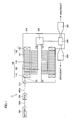
- Fig. 1 is a diagram schematically showing a structure of a drive unit to which a rotor is applied according to an embodiment of the present invention.
- drive unit 1 refers to a drive unit mounted on a hybrid vehicle that is "electric vehicle" and is configured to include a motor generator 100, a housing 200, a reduction mechanism 300, a differential mechanism 400, and a driveshaft receiving portion 500.
- Motor generator 100 is a rotating electric machine having the function of an electric motor or electric generator, and includes a rotational shaft 120 rotatably attached to housing 200 via a bearing 110, a rotor 130 attached to rotational shaft 120, and a stator 140.
- Stator 140 includes a stator core 141, and a coil 142 is wound around stator core 141.
- Coil 142 is electrically connected to a feed cable 600A via a terminal block 210 provided to housing 200.
- Feed cable 600A has another end connected to a PCU 600.
- PCU 600 is electrically connected to a battery 700 via a feed cable 700A. Accordingly, battery 700 and coil 142 are electrically connected.
- the motive energy that is output from motor generator 100 is transmitted from reduction mechanism 300 via differential mechanism 400 to driveshaft receiving portion 500.
- the drive force transmitted to driveshaft receiving portion 500 is transmitted in the form of a rotational force via a driveshaft (not shown) to wheels (not shown) to cause the vehicle to run.
- motor generator 100 driveshaft receiving portion 500, differential mechanism 400 and reduction mechanism 300.
- motor generator 100 operates as an electric generator.
- the electric power generated by motor generator 100 is stored in battery 700 via an inverter in PCU 600.
- Feed cables 600A, 700A are each a three-phase cable formed of a U phase cable, a V phase cable and a W phase cable.
- Coil 142 is formed of a U phase coil, a V phase coil and a W phase coil, and respective terminals of these three coils are connected to feed cables 600A, 700A that are each the three-phase cable.
- motor generator 100 is not limited to a hybrid vehicle (HV) and may be mounted on other "electric vehicles” (such as fuel cell vehicle and electric car for example).
- HV hybrid vehicle
- electric vehicles such as fuel cell vehicle and electric car for example.
- Fig. 2 is a longitudinal cross section of rotor 130.
- rotor 130 includes a rotor core 131 fixedly attached to rotational shaft 120 and having a magnet-inserted hole 1310 for inserting a magnet therein, a magnet 132 inserted into magnet-inserted hole 1310 to be embedded in rotor core 131, a resin portion 133 filling a clearance between the side surface of magnet-inserted hole 1310 and magnet 132, and end plates 134, 135 provided on axial end surfaces respectively of rotor core 131.
- Resin portion 133 that is "molded resin portion” is formed including an epoxy-based resin for example. Resin portion 133 is provided and accordingly magnet 132 is secured to rotor core 131. Resin portion 133 secures magnet 132 to rotor core 131 chiefly by filling the inside of magnet-inserted hole 1310. In this way, magnet 132 can be precisely fixed in magnet-inserted hole 1310.
- Magnet-inserted hole 1310 includes a first magnet-inserted hole 1311 and a second magnet-inserted hole 1312 located radially outward of rotor core 131 relative to first magnet-inserted hole 1311.
- first and second magnet-inserted holes 1311, 1312 magnets 132 are inserted respectively.
- Rotor core 131 of rotor 130 in the present embodiment is formed by stacking a plurality of electromagnetic steel sheets on each other.
- an electromagnetic steel sheet located at a position other than the axial ends and an electromagnetic steel sheet located at an axial end have respective magnet-inserted holes with respective shapes different from each other.
- Fig. 3 is a diagram showing a first sheet member 131A that is an electromagnetic steel sheet located at a position other than the axial ends of rotor core 131.
- first sheet member 131A includes first and second holes 1311A, 1312A constituting magnet-inserted hole 1310, and a third hole 1313A for reducing the weight of rotor core 131.
- first hole 1311A is constituted of two holes disposed in a substantially V-shaped arrangement.
- Second hole 1312A is provided radially outward of rotor core 131 relative to first hole 1311A in such a manner that second hole 1312A is sandwiched between first holes 1311A disposed in a substantially V-shaped arrangement.
- Second hole 1312A is formed in such a manner that a part of the second hole overlaps first holes 1311A in the radial direction of rotor core 131.
- Eight sets of first and second holes 1311A, 1312A are arranged in the circumferential direction of rotor core 131.
- rotor 130 is an eight-pole rotor having three magnets inserted per pole.
- third hole 1313A a plurality of (eight) third holes 1313A are formed in such a manner that each third hole is located between two poles.
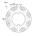
- Fig. 4 is a diagram showing second sheet member 131B that is an electromagnetic steel sheet located at an axial end of rotor core 131.
- Second sheet members 131B may be located at the two opposing ends, respectively, of rotor core 131, or second sheet member 131B may be located at one axial end only. Further, only one second sheet member 131B, or two or more second sheet members 131B laid on each other may be provided at an axial end of rotor core 131.
- second sheet member 131B includes first and second holes 1311B, 1312B constituting magnet-inserted hole 1310. More specifically, first and second holes 1311B, 1312B are formed at respective positions corresponding to respective positions of first and second holes 1311A, 1311B formed in first sheet member 131A.
- Second sheet member 131B does not have third hole 1313A as formed in first sheet member 131A.
- First hole 1311B formed in second sheet member 131B is smaller in size than first hole 1311A formed in first sheet member 131A (in Fig. 4 , respective shapes of first holes 1311A and third hole 1313A formed in first sheet member 131 A are indicated by broken lines for convenience of description).
- a part of second sheet member 131B covers first holes 1311A and third hole 1313A formed in first sheet member 131A.
- second sheet member 131B is formed to cover a radially inside axial end portion of first hole 1311A formed in first sheet member 131A and cover the whole of third hole 1313A formed in first sheet member 131A.
- Second sheet member 131B may be formed to cover a different portion of first hole 1311A formed in first sheet member 131A, and/or cover only a part of third hole 1313A formed in first sheet member 131 A.
- first sheet members 131A are stacked, and magnets 132 are inserted into first and second holes 1311A, 1312A, respectively.
- Second sheet member 131B is thereafter laid on the first sheet members.
- a resin pot that is a material for resin portion 133 is disposed on second sheet member 131B, and a resin material is caused to flow into magnet-inserted hole 1310 by a resin seal apparatus described hereinlater.
- Fig. 4 the position where this resin pot 133A is provided is drawn by a dashed-dotted line. As shown in Fig.
- resin pot 133A is provided radially inward of rotor core 131 relative to hole 1310.
- the resin material flows in the direction of arrow DR133. Since first holes 1311B on second sheet member 131B are formed relatively smaller so that a part of first holes 1311A formed in first sheet member 131A is covered. Thus, a relatively large channel is secured for the resin material carried from resin pot 133A toward second hole 1311B.
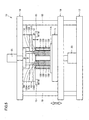
- Fig. 5 is a diagram showing a resin seal apparatus for forming resin portion 133 in rotor 130.
- resin seal apparatus 10 is configured to include a lower mold 11 on which a carry tray 11A with rotor core 131 placed thereon is mounted and which is configured to be capable of ascending and descending, and an upper mold 12 placed on rotor core 131 and configured to ascend as lower mold 11 ascends.
- Upper mold 12 includes, in a region located radially inward relative to magnet-inserted hole 1310 of rotor core 131, a plurality of resin pots 133A containing a material (referred to as tablet in some cases) for resin portion 133, and includes, in its bottom portion, a resin path 12A (referred to as runner in some cases) directing a molten liquid resin material to magnet-inserted hole 1310.
- Resin seal apparatus 10 further includes a fixed base 13 fixedly placed so that a gap serving as a working space for inserting a resin material forming resin portion 133 is formed relative to upper mold 12 located at its lower limit position, a plurality of plungers 14 passing through fixed base 13 for pressurizing the resin material fed into resin pot 133A of ascended upper mold 12, and a stopper 15 holding ascending upper mold 12 at its upper limit position.
- Fixed base 13 is attached to an upper fixed plate 16, while lower mold 11 is mounted on an ascending/descending plate 19 that moves up and down along four guide posts 18 coupling upper fixed plate 16 and a lower fixed plate 17.
- heating means (not shown) is provided to heat plunger 14 in advance and thereby facilitate extrusion of the resin material, and nullify a difference in thermal expansion between fixed base 13 and upper mold 12 and thereby eliminate displacement of the abutment between plunger 14 and resin pot 133A.
- Ascending/descending plate 19 is configured to be ascended and descended by a lower mold ascending/descending means 20 (jack for example) provided to lower fixed plate 17.
- a plurality of plungers 14 inserted into respective resin pots 133A are configured to ascend and descend in resin pot 133A at the same timing by plunger drive means 21 provided to upper fixed plate 16.
- first hole 1311A formed in first sheet member 131A is covered with second sheet member 131B located at an axial end of rotor core 131, and thus a channel where the resin material is carried to be supplied to second magnet-inserted hole 1312 located radially outward can be easily secured. More specifically, in the bottom portion of the substantially V-shaped arrangement of two first magnet-inserted holes 1311, the channel where the resin material is carried to be fed to second magnet-inserted hole 1312 can be easily secured.
- third hole 1313A is provided in first sheet member 131A, and thus the weight of rotor core 131 can be reduced.
- second sheet member 131B covers third hole 1313A, and thus the channel for supplying the resin material to magnet-inserted hole 1310 can be easily secured while the weight of rotor core 131 is reduced.
- a rotor according to the present embodiment includes: rotor core 131 formed of first sheet member 131A and second sheet member 131B corresponding to a plurality of "sheet members" stacked on each other, the rotor core having first magnet-inserted hole 1311 and second magnet-inserted hole 1312 located radially outward relative to first magnet-inserted hole 1311; magnets 132 inserted into the first and second magnet-inserted holes 1311, 1312, respectively; and resin portion 133 corresponding to "filling portion" injected into first and second magnet-inserted holes 1311, 1312.
- First sheet member 131A has first and second holes 1311A, 1312A constituting first and second magnet-inserted holes 1311, 1312, respectively.
- Second sheet member 131B is located at at least one axial end of rotor core 131 and has a portion covering a part of first hole 1311A.
- First hole 1311A includes two holes disposed in a substantially V-shaped arrangement such that the distance between the two holes increases in a radially outward direction of rotor core 131.
- Second hole 1312A is provided at a position sandwiched between the two holes disposed in the substantially V-shaped arrangement. Resin portion 133 is injected from radially inside relative to first hole 1311A into first and second holes 1311A, 1312A.
- Second sheet member 131B has a portion covering an axial end portion of the two holes, the axial end portion being located at a bottom of the substantially V-shaped arrangement.
- First sheet member 131A has third hole 1313A different from first and second holes 1311A, 1312A, and second sheet member 131B has a portion covering at least a part of third hole 1313A.
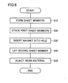
- a method of manufacturing a rotor according to the present embodiment as shown in Fig. 6 includes the steps of: forming first sheet member 131 A having first and second holes 1311 A, 1312A constituting first magnet-inserted hole 1311 and second magnet-inserted hole 1312 located radially outward relative to first magnet-inserted hole 1311, respectively, and forming second sheet member 131B having a portion covering a part of first hole 1311A when laid on first sheet member 131A (S10); stacking first sheet members 131A (S20); inserting magnets 132 respectively into first and second magnet-inserted holes 1311, 1312 formed in a stack of first sheet members 131A (S30); laying second sheet member 131B on the stack of first sheet members 131A with magnets 132 inserted in the stack (S40); and forming resin portion 133 corresponding to "filling portion” by injecting a resin material corresponding to "filler" into first and second magnet-inserted holes 1311, 1312 from above second sheet member 131B (S50).
- the present invention is applicable, for example, to a rotor included in a rotating electric machine, a method of manufacturing the rotor, and an electric vehicle including the rotor.
Landscapes
- Engineering & Computer Science (AREA)
- Power Engineering (AREA)
- Manufacturing & Machinery (AREA)
- Life Sciences & Earth Sciences (AREA)
- Sustainable Development (AREA)
- Sustainable Energy (AREA)
- Transportation (AREA)
- Mechanical Engineering (AREA)
- Permanent Field Magnets Of Synchronous Machinery (AREA)
- Manufacture Of Motors, Generators (AREA)
Abstract
Description
- The present invention relates to a rotor and a method of manufacturing the rotor as well as an electric vehicle, and particularly to a rotor included in a rotating electric machine and a method of manufacturing the rotor as well as an electric vehicle including the rotor.
- Japanese Patent Laying-Open No.
2005-184968
Here, among these electromagnetic steel sheets, at least one endmost steel sheet is a first steel sheet, and the remaining steel sheets are second steel sheets. The electromagnetic steel sheets each have a magnet hole provided to form a hole where a magnet is attached. The magnet hole in the first steel sheet is made smaller in size than the magnet hole in the second steel sheet. - When a magnet is to be embedded in the rotor core, the magnet is inserted into a magnet-inserted hole provided in the rotor core, and a filler is injected into the hole. The filler flows from above an axial end face of the rotor core into the hole. In the case where a plurality of magnets are embedded in the rotor core, a channel where the filler is carried to be fed into one magnet-inserted hole could be narrowed due to the presence of another magnet-inserted hole.
Patent Document 1 discloses no structure or feature with which this problem can be solved. - An object of the present invention is to provide a rotor in which a channel where a filler is carried to be injected into a magnet-inserted hole can be easily secured, and a method of manufacturing the rotor, as well as an electric vehicle including the rotor.
- A rotor according to the present invention includes: a rotor core formed of a plurality of sheet members stacked on each other, the rotor core having a first magnet-inserted hole and a second magnet-inserted hole located radially outward relative to the first magnet-inserted hole; magnets inserted into the first and second magnet-inserted holes, respectively; and a filling portion injected into the first and second magnet-inserted holes. The plurality of sheet members include a first sheet member having first and second holes constituting the first and second magnet-inserted holes, respectively, and a second sheet member located at at least one axial end of the rotor core and having a portion covering a part of the first hole.
- In the above-described structure, the second sheet member located at an axial end of the rotor core covers a part of the first hole formed in the first sheet member, and thus a channel where a filler is carried to be fed into the second magnet-inserted hole located radially outward can be easily secured.
- Regarding the rotor according to the present invention, "filling portion" refers to a portion intended to secure the magnet to the rotor core chiefly by filling the inside of the hole, and "filler" refers to a material constituting "filling portion."
- Further, "located radially outward" herein includes the state where a part of the second magnet-inserted hole overlaps the first magnet-inserted hole in the radial direction of the rotor core.
- According to an aspect, in the above-described rotor, the first hole includes two holes disposed in a substantially V-shaped arrangement such that a distance between the two holes increases in a radially outward direction of the rotor core, the second hole is provided at a position sandwiched between the two holes disposed in the substantially V-shaped arrangement, and the filling portion is injected from radially inside relative to the first hole into the first and second holes.
- In the above-described structure, for the rotor having three magnets per pole, the channel where the filler is carried to be fed into the second magnet-inserted hole located radially outward can be easily secured.
- In the above-described rotor, preferably the second sheet member covers an axial end portion of the two holes, the axial end portion being located at a bottom of the substantially V-shaped arrangement.
- In the above-described structure, a channel where the filler is carried to be fed into the second magnet-inserted hole can be easily secured at the bottom portion of the substantially V-shaped arrangement.
- Regarding the above-described rotor, preferably the first sheet member has a third hole different from the first and second holes, and the second sheet member has a portion covering at least a part of the third hole.
- In the above-described structure, the third hole is provided in the first sheet member and thus the weight of the rotor core can be reduced. Here, the second sheet member covers the third hole and thus a channel where the filler is carried to be fed into the magnet-inserted hole can be easily secured while the weight of the rotor core is reduced.
- By way of example, the filling portion of the above-described rotor includes resin. According to the present invention, a method of manufacturing a rotor includes the steps of: forming a first sheet member having first and second holes constituting a first magnet-inserted hole and a second magnet-inserted hole located radially outward relative to the first magnet-inserted hole, respectively, and forming a second sheet member having a portion covering a part of the first hole when laid on the first sheet member; stacking the first sheet members; inserting magnets respectively into the first and second magnet-inserted holes formed in a stack of the first sheet members; laying the second sheet member on the stack of the first sheet members with the magnets inserted in the stack; and forming a filling portion by injecting a filler into the first and second magnet-inserted holes from above the second sheet member.
- According to the above-described method, the first sheet member located at an axial end of the rotor core covers a part of the first hole constituting the first magnet-inserted hole, and thus a channel where the filler is carried to be fed into the second magnet-inserted hole located radially outward can be easily secured.
- In an aspect, according to the above-described method of manufacturing a rotor core, the filler flows from radially inside relative to the first magnet-inserted hole in the second sheet member toward the second magnet-inserted hole.
- Accordingly, the area of the axial end face of the rotor core extended by the second sheet member can be effectively used.
- An electric vehicle according to the present invention includes the above-described rotor, or the rotor manufactured according to the above-described method of manufacturing a rotor.
- According to the present invention as described above, a rotor in which a channel where a filler is carried to be injected into the magnet-inserted hole can be easily secured and a method of manufacturing the rotor can be achieved.
- It should be noted that two or more of the above-described features may be appropriately combined.
-
-
Fig. 1 is a diagram schematically showing a structure of a drive unit to which a rotor is applied according to an embodiment of the present invention. -
Fig. 2 is a longitudinal cross section showing a rotor according to an embodiment of the present invention. -
Fig. 3 is a diagram showing a first electromagnetic steel sheet that is a constituent of a rotor according to an embodiment of the present invention. -
Fig. 4 is a diagram showing a second electromagnetic steel sheet that is a constituent of a rotor according to an embodiment of the present invention. -
Fig. 5 is a diagram showing a resin seal apparatus for forming a resin portion of a rotor according to an embodiment of the present invention. -
Fig. 6 is a flowchart illustrating a method of manufacturing a rotor according to an embodiment of the present invention. - In the following, embodiments of the present invention will be described. Here, like or corresponding components are denoted by like reference characters and a description thereof may not be repeated in some cases.
- Regarding the embodiments described below, in the case where reference is made to the number of pieces, amount or the like, the scope of the present invention is not necessarily limited to the number, amount or the like unless otherwise specified. Further, in the following embodiments, each component is not necessarily a requisite component of the present invention unless otherwise specified. Furthermore, in the case where a plurality of embodiments are provided below, it is originally intended that some features of the embodiments may be appropriately combined unless otherwise specified.
-
Fig. 1 is a diagram schematically showing a structure of a drive unit to which a rotor is applied according to an embodiment of the present invention. In the example shown inFig. 1 ,drive unit 1 refers to a drive unit mounted on a hybrid vehicle that is "electric vehicle" and is configured to include amotor generator 100, ahousing 200, areduction mechanism 300, adifferential mechanism 400, and adriveshaft receiving portion 500. -
Motor generator 100 is a rotating electric machine having the function of an electric motor or electric generator, and includes arotational shaft 120 rotatably attached tohousing 200 via abearing 110, arotor 130 attached torotational shaft 120, and astator 140. Stator 140 includes astator core 141, and acoil 142 is wound aroundstator core 141.Coil 142 is electrically connected to afeed cable 600A via aterminal block 210 provided tohousing 200.Feed cable 600A has another end connected to a PCU 600. PCU 600 is electrically connected to abattery 700 via afeed cable 700A. Accordingly,battery 700 andcoil 142 are electrically connected. - The motive energy that is output from
motor generator 100 is transmitted fromreduction mechanism 300 viadifferential mechanism 400 todriveshaft receiving portion 500. The drive force transmitted todriveshaft receiving portion 500 is transmitted in the form of a rotational force via a driveshaft (not shown) to wheels (not shown) to cause the vehicle to run. - In contrast, when the hybrid vehicle is regeneratively braked, the wheels are rotated by an inertial force of the vehicle body. The rotational force from the wheels drives
motor generator 100 viadriveshaft receiving portion 500,differential mechanism 400 andreduction mechanism 300. At this time,motor generator 100 operates as an electric generator. The electric power generated bymotor generator 100 is stored inbattery 700 via an inverter in PCU 600. -
Feed cables Coil 142 is formed of a U phase coil, a V phase coil and a W phase coil, and respective terminals of these three coils are connected tofeed cables - The use of
motor generator 100 is not limited to a hybrid vehicle (HV) and may be mounted on other "electric vehicles" (such as fuel cell vehicle and electric car for example). -
Fig. 2 is a longitudinal cross section ofrotor 130. Referring toFig. 2 ,rotor 130 includes arotor core 131 fixedly attached torotational shaft 120 and having a magnet-insertedhole 1310 for inserting a magnet therein, amagnet 132 inserted into magnet-insertedhole 1310 to be embedded inrotor core 131, aresin portion 133 filling a clearance between the side surface of magnet-insertedhole 1310 andmagnet 132, andend plates rotor core 131. -
Resin portion 133 that is "molded resin portion" is formed including an epoxy-based resin for example.Resin portion 133 is provided and accordinglymagnet 132 is secured torotor core 131.Resin portion 133 securesmagnet 132 torotor core 131 chiefly by filling the inside of magnet-insertedhole 1310. In this way,magnet 132 can be precisely fixed in magnet-insertedhole 1310. - Magnet-inserted
hole 1310 includes a first magnet-insertedhole 1311 and a second magnet-insertedhole 1312 located radially outward ofrotor core 131 relative to first magnet-insertedhole 1311. In first and second magnet-insertedholes magnets 132 are inserted respectively. - First and second magnet-inserted
holes Figs. 3 and4 .Rotor core 131 ofrotor 130 in the present embodiment is formed by stacking a plurality of electromagnetic steel sheets on each other. Inrotor core 131, an electromagnetic steel sheet located at a position other than the axial ends and an electromagnetic steel sheet located at an axial end have respective magnet-inserted holes with respective shapes different from each other. -
Fig. 3 is a diagram showing afirst sheet member 131A that is an electromagnetic steel sheet located at a position other than the axial ends ofrotor core 131. Referring toFig. 3 ,first sheet member 131A includes first andsecond holes hole 1310, and athird hole 1313A for reducing the weight ofrotor core 131. More specifically,first hole 1311A is constituted of two holes disposed in a substantially V-shaped arrangement.Second hole 1312A is provided radially outward ofrotor core 131 relative tofirst hole 1311A in such a manner thatsecond hole 1312A is sandwiched betweenfirst holes 1311A disposed in a substantially V-shaped arrangement.Second hole 1312A is formed in such a manner that a part of the second hole overlapsfirst holes 1311A in the radial direction ofrotor core 131. Eight sets of first andsecond holes rotor core 131. In other words,rotor 130 is an eight-pole rotor having three magnets inserted per pole. As forthird hole 1313A, a plurality of (eight)third holes 1313A are formed in such a manner that each third hole is located between two poles. -
Fig. 4 is a diagram showingsecond sheet member 131B that is an electromagnetic steel sheet located at an axial end ofrotor core 131.Second sheet members 131B may be located at the two opposing ends, respectively, ofrotor core 131, orsecond sheet member 131B may be located at one axial end only. Further, only onesecond sheet member 131B, or two or moresecond sheet members 131B laid on each other may be provided at an axial end ofrotor core 131. - Referring to
Fig. 4 ,second sheet member 131B includes first andsecond holes hole 1310. More specifically, first andsecond holes second holes first sheet member 131A. -
Second sheet member 131B does not havethird hole 1313A as formed infirst sheet member 131A.First hole 1311B formed insecond sheet member 131B is smaller in size thanfirst hole 1311A formed infirst sheet member 131A (inFig. 4 , respective shapes offirst holes 1311A andthird hole 1313A formed infirst sheet member 131 A are indicated by broken lines for convenience of description). In other words, a part ofsecond sheet member 131B coversfirst holes 1311A andthird hole 1313A formed infirst sheet member 131A. More specifically,second sheet member 131B is formed to cover a radially inside axial end portion offirst hole 1311A formed infirst sheet member 131A and cover the whole ofthird hole 1313A formed infirst sheet member 131A.Second sheet member 131B may be formed to cover a different portion offirst hole 1311A formed infirst sheet member 131A, and/or cover only a part ofthird hole 1313A formed infirst sheet member 131 A. - In an actual process of forming
rotor core 131,first sheet members 131A are stacked, andmagnets 132 are inserted into first andsecond holes Second sheet member 131B is thereafter laid on the first sheet members. Then, a resin pot that is a material forresin portion 133 is disposed onsecond sheet member 131B, and a resin material is caused to flow into magnet-insertedhole 1310 by a resin seal apparatus described hereinlater. InFig. 4 , the position where thisresin pot 133A is provided is drawn by a dashed-dotted line. As shown inFig. 4 , for each magnet-insertedhole 1310 constituting each pole,resin pot 133A is provided radially inward ofrotor core 131 relative tohole 1310. Here, fromresin pot 133A tosecond hole 1312B constituting second magnet-insertedhole 1312, the resin material flows in the direction of arrow DR133. Sincefirst holes 1311B onsecond sheet member 131B are formed relatively smaller so that a part offirst holes 1311A formed infirst sheet member 131A is covered. Thus, a relatively large channel is secured for the resin material carried fromresin pot 133A towardsecond hole 1311B. -
Fig. 5 is a diagram showing a resin seal apparatus for formingresin portion 133 inrotor 130. Referring toFig. 5 ,resin seal apparatus 10 is configured to include alower mold 11 on which acarry tray 11A withrotor core 131 placed thereon is mounted and which is configured to be capable of ascending and descending, and anupper mold 12 placed onrotor core 131 and configured to ascend aslower mold 11 ascends.Upper mold 12 includes, in a region located radially inward relative to magnet-insertedhole 1310 ofrotor core 131, a plurality ofresin pots 133A containing a material (referred to as tablet in some cases) forresin portion 133, and includes, in its bottom portion, aresin path 12A (referred to as runner in some cases) directing a molten liquid resin material to magnet-insertedhole 1310.Resin seal apparatus 10 further includes a fixedbase 13 fixedly placed so that a gap serving as a working space for inserting a resin material formingresin portion 133 is formed relative toupper mold 12 located at its lower limit position, a plurality ofplungers 14 passing through fixedbase 13 for pressurizing the resin material fed intoresin pot 133A of ascendedupper mold 12, and astopper 15 holding ascendingupper mold 12 at its upper limit position. Fixedbase 13 is attached to an upper fixedplate 16, whilelower mold 11 is mounted on an ascending/descendingplate 19 that moves up and down along fourguide posts 18 coupling upper fixedplate 16 and a lower fixedplate 17. In fixedbase 13, heating means (not shown) is provided to heatplunger 14 in advance and thereby facilitate extrusion of the resin material, and nullify a difference in thermal expansion between fixedbase 13 andupper mold 12 and thereby eliminate displacement of the abutment betweenplunger 14 andresin pot 133A. Ascending/descendingplate 19 is configured to be ascended and descended by a lower mold ascending/descending means 20 (jack for example) provided to lower fixedplate 17. A plurality ofplungers 14 inserted intorespective resin pots 133A are configured to ascend and descend inresin pot 133A at the same timing by plunger drive means 21 provided to upper fixedplate 16. - Regarding the rotor according to the present embodiment, a part of
first hole 1311A formed infirst sheet member 131A is covered withsecond sheet member 131B located at an axial end ofrotor core 131, and thus a channel where the resin material is carried to be supplied to second magnet-insertedhole 1312 located radially outward can be easily secured. More specifically, in the bottom portion of the substantially V-shaped arrangement of two first magnet-insertedholes 1311, the channel where the resin material is carried to be fed to second magnet-insertedhole 1312 can be easily secured. - Further,
third hole 1313A is provided infirst sheet member 131A, and thus the weight ofrotor core 131 can be reduced. Here,second sheet member 131B coversthird hole 1313A, and thus the channel for supplying the resin material to magnet-insertedhole 1310 can be easily secured while the weight ofrotor core 131 is reduced. - A summary of the above-described structure is as follows. A rotor according to the present embodiment includes:
rotor core 131 formed offirst sheet member 131A andsecond sheet member 131B corresponding to a plurality of "sheet members" stacked on each other, the rotor core having first magnet-insertedhole 1311 and second magnet-insertedhole 1312 located radially outward relative to first magnet-insertedhole 1311;magnets 132 inserted into the first and second magnet-insertedholes resin portion 133 corresponding to "filling portion" injected into first and second magnet-insertedholes First sheet member 131A has first andsecond holes holes Second sheet member 131B is located at at least one axial end ofrotor core 131 and has a portion covering a part offirst hole 1311A. -
First hole 1311A includes two holes disposed in a substantially V-shaped arrangement such that the distance between the two holes increases in a radially outward direction ofrotor core 131.Second hole 1312A is provided at a position sandwiched between the two holes disposed in the substantially V-shaped arrangement.Resin portion 133 is injected from radially inside relative tofirst hole 1311A into first andsecond holes Second sheet member 131B has a portion covering an axial end portion of the two holes, the axial end portion being located at a bottom of the substantially V-shaped arrangement. -
First sheet member 131A hasthird hole 1313A different from first andsecond holes second sheet member 131B has a portion covering at least a part ofthird hole 1313A. - A method of manufacturing a rotor according to the present embodiment as shown in
Fig. 6 includes the steps of: formingfirst sheet member 131 A having first andsecond holes hole 1311 and second magnet-insertedhole 1312 located radially outward relative to first magnet-insertedhole 1311, respectively, and formingsecond sheet member 131B having a portion covering a part offirst hole 1311A when laid onfirst sheet member 131A (S10); stackingfirst sheet members 131A (S20); insertingmagnets 132 respectively into first and second magnet-insertedholes first sheet members 131A (S30); layingsecond sheet member 131B on the stack offirst sheet members 131A withmagnets 132 inserted in the stack (S40); and formingresin portion 133 corresponding to "filling portion" by injecting a resin material corresponding to "filler" into first and second magnet-insertedholes second sheet member 131B (S50). Here, the resin material flows from radially inside ofsecond sheet member 131B relative to first magnet-insertedhole 1311 toward second magnet-insertedhole 1312. - While a resin material is used as "filler" in the above-described example of the present embodiment, an adhesive, instead of the resin material, may be used as "filler" as well.
- Embodiments of the present invention have been described. It should be construed that the embodiments disclosed herein are given by way of illustration in all respects, not by way of limitation. It is intended that the scope of the present invention is defined by claims, and includes all modifications and variations equivalent in meaning and scope to the claims.
- The present invention is applicable, for example, to a rotor included in a rotating electric machine, a method of manufacturing the rotor, and an electric vehicle including the rotor.
Claims (9)
- A rotor comprising:a rotor core (131) formed of a plurality of sheet members (131A, 131B) stacked on each other, said rotor core having a first magnet-inserted hole (1311) and a second magnet-inserted hole (1312) located radially outward relative to said first magnet-inserted hole (1311);magnets (132) inserted into said first and second magnet-inserted holes (1311, 1312), respectively; anda filling portion (133) injected into said first and second magnet-inserted holes (1311, 1312),said plurality of sheet members (131A, 131B) includinga first sheet member (131A) having first and second holes (1311A, 1312A) constituting said first and second magnet-inserted holes (1311, 1312), respectively, anda second sheet member (131B) located at at least one axial end of said rotor core (131) and having a portion covering a part of said first hole (1311A).
- The rotor according to claim 1, wherein
said first hole (1311A) includes two holes disposed in a substantially V-shaped arrangement such that a distance between the two holes increases in a radially outward direction of said rotor core (131),
said second hole (1312A) is provided at a position sandwiched between said two holes disposed in the substantially V-shaped arrangement, and
said filling portion (133) is injected from radially inside relative to said first hole (1311A) into said first and second holes (1311A, 1312A). - The rotor according to claim 2, wherein
said second sheet member (131B) covers an axial end portion of said two holes, said axial end portion being located at a bottom of said substantially V-shaped arrangement. - The rotor according to claim 1, wherein
said first sheet member (131A) has a third hole (1313A) different from said first and second holes (1311A, 1312A), and
said second sheet member (131B) has a portion covering at least a part of said third hole (1313A). - The rotor according to claim 1, wherein
said filling portion (133) includes resin. - An electric vehicle including a rotor (130) as recited in claim 1.
- A method of manufacturing a rotor comprising the steps of:forming a first sheet member (131A) having first and second holes (1311A, 1312A) constituting a first magnet-inserted hole (1311) and a second magnet-inserted hole (1312) located radially outward relative to said first magnet-inserted hole (1311), respectively, and forming a second sheet member (131B) having a portion covering a part of said first hole (1311A) when laid on said first sheet member (131A);stacking said first sheet members (131A);inserting magnets (132) respectively into said first and second magnet-inserted holes (1311, 1312) formed in a stack of said first sheet members (131A);laying said second sheet member (131B) on the stack of said first sheet members (131A) with said magnets (132) inserted in said stack; andforming a filling portion (133) by injecting a filler into said first and second magnet-inserted holes (1312) from above said second sheet member (131B).
- The method of manufacturing a rotor according to claim 7, wherein
said filler flows from radially inside relative to said first magnet-inserted hole (1311) in said second sheet member (131B) toward said second magnet-inserted hole (1312). - An electric vehicle including a rotor (130) manufactured according to a method of manufacturing a rotor as recited in claim 7.
Applications Claiming Priority (2)
| Application Number | Priority Date | Filing Date | Title |
|---|---|---|---|
| JP2007104749A JP4893435B2 (en) | 2007-04-12 | 2007-04-12 | Rotor, method for manufacturing the same, and electric vehicle |
| PCT/JP2008/056530 WO2008132938A1 (en) | 2007-04-12 | 2008-03-26 | Rotor, its manufacturing method, and electric vehicle |
Publications (3)
| Publication Number | Publication Date |
|---|---|
| EP2136454A1 true EP2136454A1 (en) | 2009-12-23 |
| EP2136454A4 EP2136454A4 (en) | 2017-11-01 |
| EP2136454B1 EP2136454B1 (en) | 2022-04-13 |
Family
ID=39925398
Family Applications (1)
| Application Number | Title | Priority Date | Filing Date |
|---|---|---|---|
| EP08751826.2A Active EP2136454B1 (en) | 2007-04-12 | 2008-03-26 | Rotor, its manufacturing method, and electric vehicle |
Country Status (5)
| Country | Link |
|---|---|
| US (1) | US7960885B2 (en) |
| EP (1) | EP2136454B1 (en) |
| JP (1) | JP4893435B2 (en) |
| CN (1) | CN101657950B (en) |
| WO (1) | WO2008132938A1 (en) |
Cited By (2)
| Publication number | Priority date | Publication date | Assignee | Title |
|---|---|---|---|---|
| EP3349333A1 (en) * | 2017-01-11 | 2018-07-18 | Toyota Jidosha Kabushiki Kaisha | Rotary electric-machine rotor |
| EP4572096A1 (en) * | 2023-12-12 | 2025-06-18 | Valeo eAutomotive Germany GmbH | Rotor laminated core for an electric machine with end plates to retain a magnet |
Families Citing this family (25)
| Publication number | Priority date | Publication date | Assignee | Title |
|---|---|---|---|---|
| CN102015830B (en) | 2008-05-08 | 2013-11-13 | 东洋纺织株式会社 | Novel sulfonic acid group-containing segmentalized block copolymer, use thereof, and method for producing novel block copolymer |
| KR20110138266A (en) | 2009-04-03 | 2011-12-26 | 바스프 에스이 | Method for producing chlorine-containing polybiphenyl sulfone polymer |
| JP5748465B2 (en) * | 2010-12-07 | 2015-07-15 | 株式会社三井ハイテック | Manufacturing method of laminated iron core |
| JP5805385B2 (en) | 2010-12-14 | 2015-11-04 | 株式会社三井ハイテック | Manufacturing method of laminated iron core |
| JP2012213310A (en) * | 2011-03-18 | 2012-11-01 | Toyota Industries Corp | Electric compressor |
| JP5681027B2 (en) * | 2011-04-12 | 2015-03-04 | 株式会社三井ハイテック | Manufacturing method of laminated iron core |
| JP5799759B2 (en) * | 2011-11-09 | 2015-10-28 | 日産自動車株式会社 | Heat treatment method and heat treatment apparatus for rotor core |
| JP5981295B2 (en) | 2012-10-12 | 2016-08-31 | 株式会社三井ハイテック | Resin sealing method for laminated core |
| JP6355886B2 (en) * | 2012-11-02 | 2018-07-11 | 株式会社三井ハイテック | Resin sealing method for laminated core |
| JP5451934B1 (en) | 2012-11-06 | 2014-03-26 | 株式会社三井ハイテック | Manufacturing method of laminated iron core |
| JP5968761B2 (en) * | 2012-11-09 | 2016-08-10 | 株式会社三井ハイテック | Resin sealing method for laminated core |
| JP2015089178A (en) * | 2013-10-29 | 2015-05-07 | 三菱電機株式会社 | Permanent magnet embedded rotary electric machine |
| DE102013019318A1 (en) * | 2013-11-20 | 2015-05-21 | Brose Fahrzeugteile GmbH & Co. Kommanditgesellschaft, Würzburg | Method for producing a rotor |
| JP2015104244A (en) * | 2013-11-26 | 2015-06-04 | ファナック株式会社 | Rotor having resin hole for filling resin, and method of manufacturing rotor |
| CN103659231A (en) * | 2013-12-31 | 2014-03-26 | 泰信电机(苏州)有限公司 | Installing and reinforcing device for rotor iron core and revolving shaft |
| JP6076288B2 (en) * | 2014-03-28 | 2017-02-08 | 本田技研工業株式会社 | Rotor manufacturing method, rotor and motor |
| CN104638863B (en) * | 2015-01-23 | 2016-07-06 | 浙江迈雷科技有限公司 | A kind of permagnetic synchronous motor |
| JP6668014B2 (en) * | 2015-08-17 | 2020-03-18 | 株式会社三井ハイテック | Laminated core manufacturing equipment |
| JP6827799B2 (en) * | 2016-12-22 | 2021-02-10 | 株式会社三井ハイテック | Armature manufacturing method |
| JP6968581B2 (en) * | 2017-06-12 | 2021-11-17 | 株式会社マキタ | Electric tool |
| JP6874630B2 (en) * | 2017-10-05 | 2021-05-19 | トヨタ自動車株式会社 | Rotating electric rotor and its manufacturing method |
| CN107516953A (en) * | 2017-10-23 | 2017-12-26 | 安徽栋霖电气有限公司 | A kind of mixed type permanent-magnet pole rotor |
| JP7833268B2 (en) * | 2021-08-24 | 2026-03-19 | ニデック株式会社 | Rotors, rotating electric machines, and drive systems |
| KR102667594B1 (en) * | 2022-10-11 | 2024-05-20 | 허계용 | Rotor core for motor and method of molding magnets into rotor core |
| CN117833573A (en) * | 2023-03-29 | 2024-04-05 | 纪成伟 | Preparation method of composite permanent magnet material |
Family Cites Families (13)
| Publication number | Priority date | Publication date | Assignee | Title |
|---|---|---|---|---|
| JPH11243653A (en) * | 1998-02-23 | 1999-09-07 | Fujitsu General Ltd | Permanent magnet motor |
| JP3585814B2 (en) * | 2000-07-13 | 2004-11-04 | 三菱電機株式会社 | Recessed magnet rotor |
| JP2002136013A (en) * | 2000-10-27 | 2002-05-10 | Nissan Motor Co Ltd | Magnet motor |
| KR20020075649A (en) * | 2001-03-27 | 2002-10-05 | 삼성광주전자 주식회사 | Rotor of synchronous motor |
| JP2005184968A (en) * | 2003-12-18 | 2005-07-07 | Toyota Motor Corp | Rotating electrical machine rotor |
| JP2005184698A (en) * | 2003-12-22 | 2005-07-07 | Ngk Spark Plug Co Ltd | Laminated antenna and manufacturing method thereof |
| JP4862106B2 (en) * | 2004-09-07 | 2012-01-25 | トヨタ自動車株式会社 | Manufacturing method of motor rotor |
| JP4688505B2 (en) | 2005-01-12 | 2011-05-25 | 株式会社三井ハイテック | Rotor laminated iron core manufacturing apparatus and manufacturing method |
| JP2006314152A (en) * | 2005-05-06 | 2006-11-16 | Nissan Motor Co Ltd | Permanent magnet type motor |
| JP2007049805A (en) * | 2005-08-09 | 2007-02-22 | Honda Motor Co Ltd | Permanent magnet rotor |
| WO2007007420A1 (en) * | 2005-09-28 | 2007-01-18 | Toyota Jidosha Kabushiki Kaisha | Rotor for rotary electric machine |
| JP4856990B2 (en) * | 2006-03-13 | 2012-01-18 | トヨタ自動車株式会社 | Rotor, method for manufacturing the same, and electric vehicle |
| JP4372798B2 (en) * | 2007-02-13 | 2009-11-25 | アスモ株式会社 | Embedded magnet type motor |
-
2007
- 2007-04-12 JP JP2007104749A patent/JP4893435B2/en active Active
-
2008
- 2008-03-26 WO PCT/JP2008/056530 patent/WO2008132938A1/en not_active Ceased
- 2008-03-26 US US12/450,176 patent/US7960885B2/en active Active
- 2008-03-26 CN CN2008800117889A patent/CN101657950B/en active Active
- 2008-03-26 EP EP08751826.2A patent/EP2136454B1/en active Active
Non-Patent Citations (1)
| Title |
|---|
| See references of WO2008132938A1 * |
Cited By (4)
| Publication number | Priority date | Publication date | Assignee | Title |
|---|---|---|---|---|
| EP3349333A1 (en) * | 2017-01-11 | 2018-07-18 | Toyota Jidosha Kabushiki Kaisha | Rotary electric-machine rotor |
| AU2018200028B2 (en) * | 2017-01-11 | 2019-06-06 | Toyota Jidosha Kabushiki Kaisha | Rotary electric-machine rotor |
| US10658893B2 (en) | 2017-01-11 | 2020-05-19 | Toyota Jidosha Kabushiki Kaisha | Rotary electric-machine rotor |
| EP4572096A1 (en) * | 2023-12-12 | 2025-06-18 | Valeo eAutomotive Germany GmbH | Rotor laminated core for an electric machine with end plates to retain a magnet |
Also Published As
| Publication number | Publication date |
|---|---|
| WO2008132938A1 (en) | 2008-11-06 |
| US20100026127A1 (en) | 2010-02-04 |
| CN101657950B (en) | 2012-07-18 |
| JP2008263722A (en) | 2008-10-30 |
| US7960885B2 (en) | 2011-06-14 |
| EP2136454A4 (en) | 2017-11-01 |
| EP2136454B1 (en) | 2022-04-13 |
| JP4893435B2 (en) | 2012-03-07 |
| CN101657950A (en) | 2010-02-24 |
Similar Documents
| Publication | Publication Date | Title |
|---|---|---|
| EP2136454B1 (en) | Rotor, its manufacturing method, and electric vehicle | |
| US8058767B2 (en) | Rotor and method of manufacturing the same and electric vehicle | |
| US8492947B2 (en) | Terminal module for rotating electric machine having a guide portion, rotating electric machine, and manufacturing method thereof | |
| EP1643619B1 (en) | Coil for rotating electrical machine | |
| EP3095176B1 (en) | Rotary electric machine stator | |
| US9431860B2 (en) | Rotor and method of manufacturing rotor | |
| EP2963778B1 (en) | Stator for a rotary electric machine | |
| US20140184011A1 (en) | Stator for Rotating Electrical Machine and Rotating Electrical Machine | |
| EP2660956A1 (en) | Rotating electrical machine | |
| JP2011182552A (en) | Rotor core and rotating electrical machine core | |
| EP3116103A1 (en) | Method for manufacturing a rotary electric machine rotor and rotary electric machine rotor | |
| EP2677641A1 (en) | Rotor magnet, rotor, and rotor manufacturing method | |
| CN108696024A (en) | Winding winds parts and electric rotating machine | |
| JP4442587B2 (en) | Stator for rotating electric machine and method for manufacturing the same | |
| JP2022150091A (en) | Rotor, rotary electric machine, driving device, and moving body | |
| JP5387604B2 (en) | Terminal module for rotating electric machine and rotating electric machine | |
| JP2008271714A (en) | Manufacturing method of rotating electrical machine | |
| JP5109260B2 (en) | Rotor, method for manufacturing the same, and electric vehicle | |
| JP4775020B2 (en) | Stator fixing structure and electric vehicle | |
| US20160315509A1 (en) | Electric Machine for a Vehicle | |
| US20240356393A1 (en) | Rotor with an end plate with a curvature | |
| US20230026066A1 (en) | Rotor for an electric machine having a widened filling or venting opening | |
| CN113228467B (en) | Electric Motor | |
| JP2008043101A (en) | Rotating motor manufacturing apparatus and rotating motor manufacturing method |
Legal Events
| Date | Code | Title | Description |
|---|---|---|---|
| PUAI | Public reference made under article 153(3) epc to a published international application that has entered the european phase |
Free format text: ORIGINAL CODE: 0009012 |
|
| 17P | Request for examination filed |
Effective date: 20090923 |
|
| AK | Designated contracting states |
Kind code of ref document: A1 Designated state(s): AT BE BG CH CY CZ DE DK EE ES FI FR GB GR HR HU IE IS IT LI LT LU LV MC MT NL NO PL PT RO SE SI SK TR |
|
| DAX | Request for extension of the european patent (deleted) | ||
| RAP1 | Party data changed (applicant data changed or rights of an application transferred) |
Owner name: TOYOTA JIDOSHA KABUSHIKI KAISHA |
|
| RA4 | Supplementary search report drawn up and despatched (corrected) |
Effective date: 20171004 |
|
| RIC1 | Information provided on ipc code assigned before grant |
Ipc: H02K 15/02 20060101ALI20170926BHEP Ipc: H02K 1/27 20060101AFI20170926BHEP |
|
| STAA | Information on the status of an ep patent application or granted ep patent |
Free format text: STATUS: EXAMINATION IS IN PROGRESS |
|
| 17Q | First examination report despatched |
Effective date: 20210113 |
|
| GRAP | Despatch of communication of intention to grant a patent |
Free format text: ORIGINAL CODE: EPIDOSNIGR1 |
|
| STAA | Information on the status of an ep patent application or granted ep patent |
Free format text: STATUS: GRANT OF PATENT IS INTENDED |
|
| RIC1 | Information provided on ipc code assigned before grant |
Ipc: B60L 50/51 20190101ALI20211026BHEP Ipc: H02K 15/03 20060101ALI20211026BHEP Ipc: H02K 15/02 20060101ALI20211026BHEP Ipc: H02K 1/27 20060101AFI20211026BHEP |
|
| INTG | Intention to grant announced |
Effective date: 20211123 |
|
| GRAS | Grant fee paid |
Free format text: ORIGINAL CODE: EPIDOSNIGR3 |
|
| GRAA | (expected) grant |
Free format text: ORIGINAL CODE: 0009210 |
|
| STAA | Information on the status of an ep patent application or granted ep patent |
Free format text: STATUS: THE PATENT HAS BEEN GRANTED |
|
| AK | Designated contracting states |
Kind code of ref document: B1 Designated state(s): AT BE BG CH CY CZ DE DK EE ES FI FR GB GR HR HU IE IS IT LI LT LU LV MC MT NL NO PL PT RO SE SI SK TR |
|
| REG | Reference to a national code |
Ref country code: GB Ref legal event code: FG4D |
|
| REG | Reference to a national code |
Ref country code: CH Ref legal event code: EP |
|
| REG | Reference to a national code |
Ref country code: DE Ref legal event code: R096 Ref document number: 602008064467 Country of ref document: DE |
|
| REG | Reference to a national code |
Ref country code: IE Ref legal event code: FG4D |
|
| REG | Reference to a national code |
Ref country code: AT Ref legal event code: REF Ref document number: 1484169 Country of ref document: AT Kind code of ref document: T Effective date: 20220515 |
|
| REG | Reference to a national code |
Ref country code: LT Ref legal event code: MG9D |
|
| REG | Reference to a national code |
Ref country code: NL Ref legal event code: MP Effective date: 20220413 |
|
| REG | Reference to a national code |
Ref country code: AT Ref legal event code: MK05 Ref document number: 1484169 Country of ref document: AT Kind code of ref document: T Effective date: 20220413 |
|
| PG25 | Lapsed in a contracting state [announced via postgrant information from national office to epo] |
Ref country code: NL Free format text: LAPSE BECAUSE OF FAILURE TO SUBMIT A TRANSLATION OF THE DESCRIPTION OR TO PAY THE FEE WITHIN THE PRESCRIBED TIME-LIMIT Effective date: 20220413 |
|
| PG25 | Lapsed in a contracting state [announced via postgrant information from national office to epo] |
Ref country code: SE Free format text: LAPSE BECAUSE OF FAILURE TO SUBMIT A TRANSLATION OF THE DESCRIPTION OR TO PAY THE FEE WITHIN THE PRESCRIBED TIME-LIMIT Effective date: 20220413 Ref country code: PT Free format text: LAPSE BECAUSE OF FAILURE TO SUBMIT A TRANSLATION OF THE DESCRIPTION OR TO PAY THE FEE WITHIN THE PRESCRIBED TIME-LIMIT Effective date: 20220816 Ref country code: NO Free format text: LAPSE BECAUSE OF FAILURE TO SUBMIT A TRANSLATION OF THE DESCRIPTION OR TO PAY THE FEE WITHIN THE PRESCRIBED TIME-LIMIT Effective date: 20220713 Ref country code: LT Free format text: LAPSE BECAUSE OF FAILURE TO SUBMIT A TRANSLATION OF THE DESCRIPTION OR TO PAY THE FEE WITHIN THE PRESCRIBED TIME-LIMIT Effective date: 20220413 Ref country code: HR Free format text: LAPSE BECAUSE OF FAILURE TO SUBMIT A TRANSLATION OF THE DESCRIPTION OR TO PAY THE FEE WITHIN THE PRESCRIBED TIME-LIMIT Effective date: 20220413 Ref country code: GR Free format text: LAPSE BECAUSE OF FAILURE TO SUBMIT A TRANSLATION OF THE DESCRIPTION OR TO PAY THE FEE WITHIN THE PRESCRIBED TIME-LIMIT Effective date: 20220714 Ref country code: FI Free format text: LAPSE BECAUSE OF FAILURE TO SUBMIT A TRANSLATION OF THE DESCRIPTION OR TO PAY THE FEE WITHIN THE PRESCRIBED TIME-LIMIT Effective date: 20220413 Ref country code: ES Free format text: LAPSE BECAUSE OF FAILURE TO SUBMIT A TRANSLATION OF THE DESCRIPTION OR TO PAY THE FEE WITHIN THE PRESCRIBED TIME-LIMIT Effective date: 20220413 Ref country code: BG Free format text: LAPSE BECAUSE OF FAILURE TO SUBMIT A TRANSLATION OF THE DESCRIPTION OR TO PAY THE FEE WITHIN THE PRESCRIBED TIME-LIMIT Effective date: 20220713 Ref country code: AT Free format text: LAPSE BECAUSE OF FAILURE TO SUBMIT A TRANSLATION OF THE DESCRIPTION OR TO PAY THE FEE WITHIN THE PRESCRIBED TIME-LIMIT Effective date: 20220413 |
|
| PG25 | Lapsed in a contracting state [announced via postgrant information from national office to epo] |
Ref country code: PL Free format text: LAPSE BECAUSE OF FAILURE TO SUBMIT A TRANSLATION OF THE DESCRIPTION OR TO PAY THE FEE WITHIN THE PRESCRIBED TIME-LIMIT Effective date: 20220413 Ref country code: LV Free format text: LAPSE BECAUSE OF FAILURE TO SUBMIT A TRANSLATION OF THE DESCRIPTION OR TO PAY THE FEE WITHIN THE PRESCRIBED TIME-LIMIT Effective date: 20220413 Ref country code: IS Free format text: LAPSE BECAUSE OF FAILURE TO SUBMIT A TRANSLATION OF THE DESCRIPTION OR TO PAY THE FEE WITHIN THE PRESCRIBED TIME-LIMIT Effective date: 20220813 |
|
| REG | Reference to a national code |
Ref country code: DE Ref legal event code: R097 Ref document number: 602008064467 Country of ref document: DE |
|
| PG25 | Lapsed in a contracting state [announced via postgrant information from national office to epo] |
Ref country code: SK Free format text: LAPSE BECAUSE OF FAILURE TO SUBMIT A TRANSLATION OF THE DESCRIPTION OR TO PAY THE FEE WITHIN THE PRESCRIBED TIME-LIMIT Effective date: 20220413 Ref country code: RO Free format text: LAPSE BECAUSE OF FAILURE TO SUBMIT A TRANSLATION OF THE DESCRIPTION OR TO PAY THE FEE WITHIN THE PRESCRIBED TIME-LIMIT Effective date: 20220413 Ref country code: EE Free format text: LAPSE BECAUSE OF FAILURE TO SUBMIT A TRANSLATION OF THE DESCRIPTION OR TO PAY THE FEE WITHIN THE PRESCRIBED TIME-LIMIT Effective date: 20220413 Ref country code: DK Free format text: LAPSE BECAUSE OF FAILURE TO SUBMIT A TRANSLATION OF THE DESCRIPTION OR TO PAY THE FEE WITHIN THE PRESCRIBED TIME-LIMIT Effective date: 20220413 Ref country code: CZ Free format text: LAPSE BECAUSE OF FAILURE TO SUBMIT A TRANSLATION OF THE DESCRIPTION OR TO PAY THE FEE WITHIN THE PRESCRIBED TIME-LIMIT Effective date: 20220413 |
|
| PLBE | No opposition filed within time limit |
Free format text: ORIGINAL CODE: 0009261 |
|
| STAA | Information on the status of an ep patent application or granted ep patent |
Free format text: STATUS: NO OPPOSITION FILED WITHIN TIME LIMIT |
|
| 26N | No opposition filed |
Effective date: 20230116 |
|
| PG25 | Lapsed in a contracting state [announced via postgrant information from national office to epo] |
Ref country code: SI Free format text: LAPSE BECAUSE OF FAILURE TO SUBMIT A TRANSLATION OF THE DESCRIPTION OR TO PAY THE FEE WITHIN THE PRESCRIBED TIME-LIMIT Effective date: 20220413 |
|
| P01 | Opt-out of the competence of the unified patent court (upc) registered |
Effective date: 20230427 |
|
| REG | Reference to a national code |
Ref country code: DE Ref legal event code: R084 Ref document number: 602008064467 Country of ref document: DE |
|
| PG25 | Lapsed in a contracting state [announced via postgrant information from national office to epo] |
Ref country code: MC Free format text: LAPSE BECAUSE OF FAILURE TO SUBMIT A TRANSLATION OF THE DESCRIPTION OR TO PAY THE FEE WITHIN THE PRESCRIBED TIME-LIMIT Effective date: 20220413 |
|
| REG | Reference to a national code |
Ref country code: CH Ref legal event code: PL |
|
| GBPC | Gb: european patent ceased through non-payment of renewal fee |
Effective date: 20230326 |
|
| REG | Reference to a national code |
Ref country code: BE Ref legal event code: MM Effective date: 20230331 |
|
| PG25 | Lapsed in a contracting state [announced via postgrant information from national office to epo] |
Ref country code: LU Free format text: LAPSE BECAUSE OF NON-PAYMENT OF DUE FEES Effective date: 20230326 |
|
| REG | Reference to a national code |
Ref country code: IE Ref legal event code: MM4A |
|
| PG25 | Lapsed in a contracting state [announced via postgrant information from national office to epo] |
Ref country code: GB Free format text: LAPSE BECAUSE OF NON-PAYMENT OF DUE FEES Effective date: 20230326 |
|
| PG25 | Lapsed in a contracting state [announced via postgrant information from national office to epo] |
Ref country code: LI Free format text: LAPSE BECAUSE OF NON-PAYMENT OF DUE FEES Effective date: 20230331 Ref country code: IT Free format text: LAPSE BECAUSE OF FAILURE TO SUBMIT A TRANSLATION OF THE DESCRIPTION OR TO PAY THE FEE WITHIN THE PRESCRIBED TIME-LIMIT Effective date: 20220413 Ref country code: IE Free format text: LAPSE BECAUSE OF NON-PAYMENT OF DUE FEES Effective date: 20230326 Ref country code: GB Free format text: LAPSE BECAUSE OF NON-PAYMENT OF DUE FEES Effective date: 20230326 Ref country code: FR Free format text: LAPSE BECAUSE OF NON-PAYMENT OF DUE FEES Effective date: 20230331 Ref country code: CH Free format text: LAPSE BECAUSE OF NON-PAYMENT OF DUE FEES Effective date: 20230331 |
|
| PG25 | Lapsed in a contracting state [announced via postgrant information from national office to epo] |
Ref country code: BE Free format text: LAPSE BECAUSE OF NON-PAYMENT OF DUE FEES Effective date: 20230331 |
|
| PG25 | Lapsed in a contracting state [announced via postgrant information from national office to epo] |
Ref country code: BG Free format text: LAPSE BECAUSE OF FAILURE TO SUBMIT A TRANSLATION OF THE DESCRIPTION OR TO PAY THE FEE WITHIN THE PRESCRIBED TIME-LIMIT Effective date: 20220413 |
|
| PG25 | Lapsed in a contracting state [announced via postgrant information from national office to epo] |
Ref country code: BG Free format text: LAPSE BECAUSE OF FAILURE TO SUBMIT A TRANSLATION OF THE DESCRIPTION OR TO PAY THE FEE WITHIN THE PRESCRIBED TIME-LIMIT Effective date: 20220413 |
|
| PG25 | Lapsed in a contracting state [announced via postgrant information from national office to epo] |
Ref country code: CY Free format text: LAPSE BECAUSE OF FAILURE TO SUBMIT A TRANSLATION OF THE DESCRIPTION OR TO PAY THE FEE WITHIN THE PRESCRIBED TIME-LIMIT; INVALID AB INITIO Effective date: 20080326 |
|
| PG25 | Lapsed in a contracting state [announced via postgrant information from national office to epo] |
Ref country code: HU Free format text: LAPSE BECAUSE OF FAILURE TO SUBMIT A TRANSLATION OF THE DESCRIPTION OR TO PAY THE FEE WITHIN THE PRESCRIBED TIME-LIMIT; INVALID AB INITIO Effective date: 20080326 |
|
| PG25 | Lapsed in a contracting state [announced via postgrant information from national office to epo] |
Ref country code: TR Free format text: LAPSE BECAUSE OF FAILURE TO SUBMIT A TRANSLATION OF THE DESCRIPTION OR TO PAY THE FEE WITHIN THE PRESCRIBED TIME-LIMIT Effective date: 20220413 |
|
| PGFP | Annual fee paid to national office [announced via postgrant information from national office to epo] |
Ref country code: DE Payment date: 20260128 Year of fee payment: 19 |