EP2136172A1 - Four à arc - Google Patents
Four à arc Download PDFInfo
- Publication number
- EP2136172A1 EP2136172A1 EP08010980A EP08010980A EP2136172A1 EP 2136172 A1 EP2136172 A1 EP 2136172A1 EP 08010980 A EP08010980 A EP 08010980A EP 08010980 A EP08010980 A EP 08010980A EP 2136172 A1 EP2136172 A1 EP 2136172A1
- Authority
- EP
- European Patent Office
- Prior art keywords
- measuring
- arc furnace
- furnace
- electric arc
- bay
- Prior art date
- Legal status (The legal status is an assumption and is not a legal conclusion. Google has not performed a legal analysis and makes no representation as to the accuracy of the status listed.)
- Withdrawn
Links
Images
Classifications
-
- F—MECHANICAL ENGINEERING; LIGHTING; HEATING; WEAPONS; BLASTING
- F27—FURNACES; KILNS; OVENS; RETORTS
- F27B—FURNACES, KILNS, OVENS, OR RETORTS IN GENERAL; OPEN SINTERING OR LIKE APPARATUS
- F27B3/00—Hearth-type furnaces, e.g. of reverberatory type; Tank furnaces
- F27B3/08—Hearth-type furnaces, e.g. of reverberatory type; Tank furnaces heated electrically, with or without any other source of heat
- F27B3/085—Arc furnaces
-
- C—CHEMISTRY; METALLURGY
- C21—METALLURGY OF IRON
- C21C—PROCESSING OF PIG-IRON, e.g. REFINING, MANUFACTURE OF WROUGHT-IRON OR STEEL; TREATMENT IN MOLTEN STATE OF FERROUS ALLOYS
- C21C5/00—Manufacture of carbon-steel, e.g. plain mild steel, medium carbon steel or cast steel or stainless steel
- C21C5/52—Manufacture of steel in electric furnaces
- C21C5/5211—Manufacture of steel in electric furnaces in an alternating current [AC] electric arc furnace
-
- C—CHEMISTRY; METALLURGY
- C21—METALLURGY OF IRON
- C21C—PROCESSING OF PIG-IRON, e.g. REFINING, MANUFACTURE OF WROUGHT-IRON OR STEEL; TREATMENT IN MOLTEN STATE OF FERROUS ALLOYS
- C21C5/00—Manufacture of carbon-steel, e.g. plain mild steel, medium carbon steel or cast steel or stainless steel
- C21C5/52—Manufacture of steel in electric furnaces
- C21C5/527—Charging of the electric furnace
-
- F—MECHANICAL ENGINEERING; LIGHTING; HEATING; WEAPONS; BLASTING
- F27—FURNACES; KILNS; OVENS; RETORTS
- F27B—FURNACES, KILNS, OVENS, OR RETORTS IN GENERAL; OPEN SINTERING OR LIKE APPARATUS
- F27B3/00—Hearth-type furnaces, e.g. of reverberatory type; Tank furnaces
- F27B3/10—Details, accessories, or equipment peculiar to hearth-type furnaces
- F27B3/28—Arrangement of controlling, monitoring, alarm or the like devices
-
- C—CHEMISTRY; METALLURGY
- C21—METALLURGY OF IRON
- C21C—PROCESSING OF PIG-IRON, e.g. REFINING, MANUFACTURE OF WROUGHT-IRON OR STEEL; TREATMENT IN MOLTEN STATE OF FERROUS ALLOYS
- C21C5/00—Manufacture of carbon-steel, e.g. plain mild steel, medium carbon steel or cast steel or stainless steel
- C21C5/52—Manufacture of steel in electric furnaces
- C21C2005/5288—Measuring or sampling devices
-
- Y—GENERAL TAGGING OF NEW TECHNOLOGICAL DEVELOPMENTS; GENERAL TAGGING OF CROSS-SECTIONAL TECHNOLOGIES SPANNING OVER SEVERAL SECTIONS OF THE IPC; TECHNICAL SUBJECTS COVERED BY FORMER USPC CROSS-REFERENCE ART COLLECTIONS [XRACs] AND DIGESTS
- Y02—TECHNOLOGIES OR APPLICATIONS FOR MITIGATION OR ADAPTATION AGAINST CLIMATE CHANGE
- Y02P—CLIMATE CHANGE MITIGATION TECHNOLOGIES IN THE PRODUCTION OR PROCESSING OF GOODS
- Y02P10/00—Technologies related to metal processing
- Y02P10/20—Recycling
Definitions
- the invention relates to an electric arc furnace with a bay panel and a lower vessel, which has an eccentrically arranged tap hole.
- arc furnaces which are also referred to as electric arc furnaces.
- the starting material ie the steel scrap serving as starting material
- the steel scrap is heated with the aid of an arc burning between an electrode and the latter and finally melted.
- the steel scrap can be additionally heated with burners.
- the monitoring of the melting process is carried out by means of a measuring device having a probe head with lances attached to it extendably attached. At the tip of the lances are, for example, a temperature probe or a sampling probe.
- the measurements are carried out with the work door or slag door open due to the slag-door flare.
- the measurement can be done through a special opening in the lid of the arc furnace.
- the measuring devices are mounted near the work door on the furnace, and have a robotic arm or manipulator, which with the lances equipped equipped measuring head.
- there are mobile measuring systems that can be moved in front of the slag door opening in order to immerse a measuring lance in the melt when the door is open.
- a temperature measuring probe typically consists of a cardboard tube, which is fitted onto the lance tube, at the end of which a ceramic head with a thermocouple arranged in a quartz glass attachment is located.
- the temperature measuring probe which is suitable for single use only, is immersed in the liquid melt for a few seconds with the aid of the lance for the purpose of the measurement.
- a sampling probe also has a cardboard tube, at the end of which a mold for receiving penetrating into the probe and there solidifying material is present.
- a sampling probe is also suitable for single use only.
- the known measuring systems which predominantly determine the temperature of the melt through the slag door opening or remove a sample from the melt, are predominantly hand-guided, so that for the purpose of the measurement a person must be in the danger zone of the arc furnace. There is also the problem that slag or scrap residues may be in the slag door area, making measurement difficult or even impossible.
- the object of the present invention is to specify an electric arc furnace with a measuring device which is improved with regard to the problems existing in the prior art and in particular enables a simple and reliable measurement or sampling on the melt.
- the electric arc furnace according to the invention has a bay panel, a lower vessel which has an eccentrically arranged tapping opening, and a measuring device.
- the measuring device In turn, at least one measuring lance, which can be extended and attached to a measuring head, can be positioned above the bay panel in a working position such that the measuring lance can be inserted into the melting chamber of the arc furnace through an opening provided in the bay panel.
- the measuring lance Since the measuring lance is introduced into the melting space through an opening provided in the bay panel, a probe arranged at the tip of the measuring lance can be immersed in the molten space in the molten space by a short path. It is also possible to insert the measuring lance both straight and diagonally into the melting chamber. If the measuring lance is inserted in a straight line into the melting chamber, the probe can penetrate particularly deeply into the interior of the furnace, making the measurement more accurate. If the measuring lance is introduced obliquely into the melting chamber, a large distance between the Ofenausmautation and the probe is maintained. The likelihood of the probe colliding with the lining or any slag caking thereon may be reduced.
- electric arc furnaces used for scrap treatment have various openings in the area of their bay stage, more precisely, in the bay window, which terminates the melting space in relation to the environment and which can also be designed as a cooling panel.
- this will be retrofitted with a corresponding measuring device.
- known measuring methods in which a probe is introduced into the melt through the slag door opening, the problem often arises that the slag door opening is blocked by scrap residues or slag accumulations. A measurement is difficult or even impossible.
- the lying below the bay panel area of the melting space is largely protected from slag contamination, so that a measurement in this area is particularly reliable feasible.
- the area of the bay is easily accessible for maintenance through the Erkekühne, so if necessary At the measuring device occurring disturbance the service staff has easy access. In the event of a serious disturbance, in which the access opening in the area of the bay panel is blocked by the measuring device, the slag door opening remains accessible, so that in case of doubt, a measurement can be carried out in a conventional manner.
- the electric arc furnace has a positioning device provided for positioning the measuring head, which is set up on a furnace platform of the electric arc furnace.
- a furnace platform is a platform surrounding the bottom of the arc furnace, which extends slightly below the bay panel.
- the positioning device can be easily installed because this is easy to reach, for example, for the hall crane.
- the measuring device does not hinder the charging of scrap in the arc furnace nor the addition of alloy materials in the pan. In addition, it is easy to reach for the service staff at this point.
- the positioning device is placed according to an embodiment on that side of the furnace platform, which is the pivoting device for the lid of the arc furnace opposite.
- the probes for electric arc furnaces in scrap recycling are typically usable only once. After measurement or sampling, the replacement of the probe requires therefore the stay of a technician in the danger area of the electric arc furnace.
- This can be prevented in an electric arc furnace according to an embodiment in which the probes are automatically recharged from a magazine.
- the measuring head of the measuring device can be positioned between a rest and the working position and comprises a probe magazine which is suitable for the automatic recording of probes by the measuring lance - in the rest position of the measuring head.
- the control of various process parameters during the reflow process is of interest.
- the arc furnace according to a further embodiment, a measuring device whose measuring lance is suitable for receiving a plurality of probes. With the aid of such a measuring device, it is possible to carry out several measurements with different probes simultaneously or in short time intervals. The positioning of the measuring head only has to be done once. Within a short time, a large number of parameters can be measured with little effort.
- An important process variable is the temperature of the melt.
- the arc furnace comprises a measuring device having a measuring lance, which is suitable for receiving a temperature probe.
- the composition of the melt is another important parameter that has a decisive effect on the quality of the steel.
- An arc furnace according to a further embodiment therefore comprises a measuring device with a measuring lance which is suitable for receiving a sampling probe.
- the positioning device is a multi-joint arm manipulator. This allows a flexible movement of the measuring head; it is in particular possible to avoid obstacles in the area of the bay panel, and thus to ensure a reliable positioning of the measuring lance.
- the articulated arm manipulator is a Viergelenkarmmanipulator.
- a Gelenkarmmanipulator In such a manipulator, only one drive member is needed to move all the members.
- a Gelenkarmmanipulator also has only rotary joints between the individual members of the articulated arm, which are less susceptible to dirt. It is also advantageous that the measuring head held on the manipulator is always held in the same orientation and does not pitch. This allows a simple and precise positioning of the measuring head.
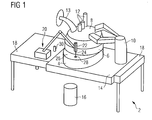
- FIG. 1 An electric arc furnace 2 (also called an electic arc furnance) for reprocessing steel scrap is known in FIG. 1 shown.
- This consists of a lower vessel 4 and an adjoining upper vessel 6.
- the surrounded by the lower and upper vessel 4,6 melting chamber of the arc furnace 2 is closed to the top through a lid 8.
- This can be pivoted to fill the arc furnace 2 with starting material / steel scrap by means of a pivoting device 10 (also referred to as portal) to the side.
- a pivoting device 10 also referred to as portal
- the arc furnace 2 is held on its lower vessel 4 in a cradle 14, which can be tilted so that the molten steel can be poured into a pan 16 for emptying the melting space.
- a cradle 14 On both sides of the cradle 14 is the oven platform 18, which in contrast to this is not tiltable.
- the pivoting device 10 for the lid 8 is placed on the cradle 14.
- a measuring device 20 is placed on the furnace platform 18, which is attached to a measuring head 22 measuring lance 24 can be inserted through a present in a bay 26 opening 28 into the melting chamber of the arc furnace arc 2.
- the bay panel 26 extends in a plane between the lower and upper vessel 4, 6 of the arc furnace 2, and closes this off from its outer space.
- the bay panel 26 may also be configured as a cooling panel.
- the bay panel 26 is located in front of an existing in the lower vessel 2, eccentrically arranged tap hole in the vertical direction. The bay panel 26 is thus located substantially above the existing in the lower vessel 2 tap hole.
- the bay panel 26 is particularly accessible for maintenance on a bay window.
- the bay panel 26 has an opening which is used to fill the tapping opening after emptying the arc furnace 2.
- a bay burner for additional heating of the melt can in the area of the bay of the arc furnace 2, which the bay panel 26 terminates to its upper side, a bay burner.
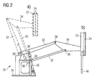
- measuring device 20 is in the FIG. 2a, b shown in detail.
- the measuring device 20 is pivotable between a rest and a working position; FIG. 2a shows the rest, FIG. 2b the working position of the measuring device 20.
- the measuring device 20 is in connection with the FIG. 2a, b explained in more detail.
- the arc furnace 2 will be explained with reference to FIG FIG. 1 further explained.
- the measuring device 20 can record using the measuring lance 24 in its rest position from a probe magazine 30 different measuring probes or sampling probes.
- the change of the measuring probes can be done automatically.
- Typical probes are temperature probes, sampling probes or oxygen activity measuring probes which, for example, allow the possibility of rapid melt melt analysis.
- the measuring device 20 positions the measuring head 22 above the bay 26, so that the measuring lance 24 can be immersed in the melt by the opening 28 present in the bay 26.
- the measuring head 22 can be tilted in such a way so that the measuring lance 24 can be introduced at different angles into the melting space.
- bay window burner In many arc furnaces, there is a not in the area of the bay FIG. 1 illustrated bay window burner.
- the bay 26 is a usually closed with a copper plate opening which - after emptying of the arc furnace 2 - is used to fill the tap hole. This very opening is well suited to introduce the measuring lance 24 of a measuring device 20, as described above, into the melting space.
- the measuring device 20 is placed on the pivoting device 10 for the lid 8 of the arc furnace 2 opposite side of the arc furnace 2 on the furnace platform 18. At this location, the measuring device 20 hinders the pivotal movement of the lid 8 when opening the arc furnace 2 least.
- the measuring device 20 can also be set up at another suitable location. The decisive factor is that it is possible to position the measuring head 22 over the bay 26.
- FIG. 2a, b they already show FIG. 1 known measuring device 20 each in a detailed side view.
- the measuring device 20, which is set up on the oven platform 18, has a positioning device comprising a plurality of articulated rods 32 and a head part 34, which is movable via a hydraulic cylinder 36. Joint rods 32, head portion 34 and the hydraulic cylinder 36 are interconnected by hinges 38.
- the measuring head 22, which according to the illustrated embodiment is suitable for receiving two measuring lances 24, is supported by the head part 34. Due to the construction of the positioning device as Viergelenkarmmanipulator the measuring head 22 can be moved without pitching movement between the rest and the working position.
- the measuring head 22 comprises a lifting device for the measuring lances 24, and with respect to the pivot plane of the joint rods 32 is rotated by 90 ° attached to the head part 34.
- the measuring lances 24 can be immersed by the existing in the bay 26 panel opening 28 in the present in the melting chamber of the arc furnace 2 melt.
- the probe 40 located at the tip of the measuring lance 24 is immersed in the melt at about 400 mm.
Priority Applications (5)
| Application Number | Priority Date | Filing Date | Title |
|---|---|---|---|
| EP08010980A EP2136172A1 (fr) | 2008-06-17 | 2008-06-17 | Four à arc |
| MX2010013585A MX340009B (es) | 2008-06-17 | 2009-04-01 | Horno de arco. |
| RU2011101398/02A RU2473030C2 (ru) | 2008-06-17 | 2009-04-01 | Дуговая электрическая печь |
| DE112009001123T DE112009001123A5 (de) | 2008-06-17 | 2009-04-01 | Lichtbogenofen |
| PCT/EP2009/053863 WO2009153075A1 (fr) | 2008-06-17 | 2009-04-01 | Four à arc |
Applications Claiming Priority (1)
| Application Number | Priority Date | Filing Date | Title |
|---|---|---|---|
| EP08010980A EP2136172A1 (fr) | 2008-06-17 | 2008-06-17 | Four à arc |
Publications (1)
| Publication Number | Publication Date |
|---|---|
| EP2136172A1 true EP2136172A1 (fr) | 2009-12-23 |
Family
ID=39955566
Family Applications (1)
| Application Number | Title | Priority Date | Filing Date |
|---|---|---|---|
| EP08010980A Withdrawn EP2136172A1 (fr) | 2008-06-17 | 2008-06-17 | Four à arc |
Country Status (5)
| Country | Link |
|---|---|
| EP (1) | EP2136172A1 (fr) |
| DE (1) | DE112009001123A5 (fr) |
| MX (1) | MX340009B (fr) |
| RU (1) | RU2473030C2 (fr) |
| WO (1) | WO2009153075A1 (fr) |
Cited By (1)
| Publication number | Priority date | Publication date | Assignee | Title |
|---|---|---|---|---|
| WO2023224496A1 (fr) | 2022-05-20 | 2023-11-23 | Momek Tappingmate As | Système de piquage robotique pour four à arc électrique |
Families Citing this family (1)
| Publication number | Priority date | Publication date | Assignee | Title |
|---|---|---|---|---|
| WO2021133189A1 (fr) * | 2019-12-25 | 2021-07-01 | Schlumberger Technology Corporation | Échantillonneurs de gaz et procédés associés |
Citations (8)
| Publication number | Priority date | Publication date | Assignee | Title |
|---|---|---|---|---|
| US4965813A (en) * | 1989-07-25 | 1990-10-23 | Nikko Industry Co., Ltd. | Combustion aiding apparatus for steel-making electric-arc-furnace |
| JPH05181544A (ja) * | 1991-12-27 | 1993-07-23 | Kurosaki Refract Co Ltd | 電気炉精錬における溶鋼温度のコントロール方法 |
| JPH0873920A (ja) * | 1994-09-01 | 1996-03-19 | Nisshin Steel Co Ltd | 電気炉用酸素吹込み装置 |
| JPH08320181A (ja) * | 1995-05-26 | 1996-12-03 | Nikko:Kk | 炉底出鋼型電気炉のランス駆動装置 |
| DE19820589A1 (de) * | 1998-05-08 | 1999-11-11 | Wilfried Stein | Elektrolichtbogenofen |
| WO2000012767A1 (fr) * | 1998-08-28 | 2000-03-09 | Voest-Alpine Industrieanlagenbau Gmbh | Procede de production d'une masse metallique en fusion et lance multifonction utilisee |
| WO2000053987A1 (fr) * | 1999-03-09 | 2000-09-14 | Paul Wurth S.A. | Procede de declenchement de la coulee dans un four a arc et dispositif de mesure et d'echantillonnage |
| JP2002080910A (ja) * | 2000-09-11 | 2002-03-22 | Topy Ind Ltd | プローブの自動回収装置 |
Family Cites Families (5)
| Publication number | Priority date | Publication date | Assignee | Title |
|---|---|---|---|---|
| SU611936A1 (ru) * | 1976-12-06 | 1978-06-25 | Институт черной металлургии | Устройство дл ввода зонда в конвертер |
| SU800690A1 (ru) * | 1978-02-16 | 1981-01-30 | Криворожский Филиал Киевского Институтаавтоматики Им. Хху Съезда Кпсс | Устройство дл измерени температурыжидКОгО МЕТАллА |
| RU2078459C1 (ru) * | 1994-09-15 | 1997-04-27 | Малое коллективное научно-исследовательское предприятие "Алкор" | Способ измерений температуры жидких металлов и неметаллических высокотемпературных сред |
| US6499777B1 (en) * | 1999-05-11 | 2002-12-31 | Matrix Integrated Systems, Inc. | End-effector with integrated cooling mechanism |
| ES2265539T3 (es) * | 2002-08-20 | 2007-02-16 | Sms Demag Aktiengesellschaft | Instalacion de doble horno para la produccion de materiales de acero. |
-
2008
- 2008-06-17 EP EP08010980A patent/EP2136172A1/fr not_active Withdrawn
-
2009
- 2009-04-01 RU RU2011101398/02A patent/RU2473030C2/ru not_active IP Right Cessation
- 2009-04-01 WO PCT/EP2009/053863 patent/WO2009153075A1/fr active Application Filing
- 2009-04-01 MX MX2010013585A patent/MX340009B/es active IP Right Grant
- 2009-04-01 DE DE112009001123T patent/DE112009001123A5/de not_active Withdrawn
Patent Citations (8)
| Publication number | Priority date | Publication date | Assignee | Title |
|---|---|---|---|---|
| US4965813A (en) * | 1989-07-25 | 1990-10-23 | Nikko Industry Co., Ltd. | Combustion aiding apparatus for steel-making electric-arc-furnace |
| JPH05181544A (ja) * | 1991-12-27 | 1993-07-23 | Kurosaki Refract Co Ltd | 電気炉精錬における溶鋼温度のコントロール方法 |
| JPH0873920A (ja) * | 1994-09-01 | 1996-03-19 | Nisshin Steel Co Ltd | 電気炉用酸素吹込み装置 |
| JPH08320181A (ja) * | 1995-05-26 | 1996-12-03 | Nikko:Kk | 炉底出鋼型電気炉のランス駆動装置 |
| DE19820589A1 (de) * | 1998-05-08 | 1999-11-11 | Wilfried Stein | Elektrolichtbogenofen |
| WO2000012767A1 (fr) * | 1998-08-28 | 2000-03-09 | Voest-Alpine Industrieanlagenbau Gmbh | Procede de production d'une masse metallique en fusion et lance multifonction utilisee |
| WO2000053987A1 (fr) * | 1999-03-09 | 2000-09-14 | Paul Wurth S.A. | Procede de declenchement de la coulee dans un four a arc et dispositif de mesure et d'echantillonnage |
| JP2002080910A (ja) * | 2000-09-11 | 2002-03-22 | Topy Ind Ltd | プローブの自動回収装置 |
Cited By (1)
| Publication number | Priority date | Publication date | Assignee | Title |
|---|---|---|---|---|
| WO2023224496A1 (fr) | 2022-05-20 | 2023-11-23 | Momek Tappingmate As | Système de piquage robotique pour four à arc électrique |
Also Published As
| Publication number | Publication date |
|---|---|
| DE112009001123A5 (de) | 2011-06-16 |
| MX2010013585A (es) | 2011-01-21 |
| WO2009153075A1 (fr) | 2009-12-23 |
| MX340009B (es) | 2016-06-17 |
| RU2473030C2 (ru) | 2013-01-20 |
| RU2011101398A (ru) | 2012-07-27 |
Similar Documents
| Publication | Publication Date | Title |
|---|---|---|
| AT502058B1 (de) | Stranggiessanlage mit mindestens einem multifunktions-roboter | |
| EP2056983B1 (fr) | Procédé de maintenance d'une fermeture coulissante montée au niveau du bec d'un récipient pour bain de fusion | |
| EP3892947B1 (fr) | Dispositif et méthode d'entretien du trou de coulée d'un four à arc électrique | |
| EP2255905B1 (fr) | Appareil pour effectuer des travaux à l'intérieur d'un récipient métallurgique | |
| WO2009138297A1 (fr) | Installation de four | |
| EP2992287B1 (fr) | Four de fusion et joint cardanique pour le support de la barre porte-électrode d'un four de fusion | |
| DE10223284A1 (de) | Verfahren zum Reparieren einer Schutzauskleidung eines Industriellen Reaktions- oder Transportgefäßes | |
| WO2011095377A1 (fr) | Dispositif de détection d'au moins une valeur de mesure sur un four, et four | |
| WO2011012595A1 (fr) | Dispositif pour basculer un récipient de fusion métallurgique, agencement de fusion métallurgique et procédé avec l'utilisation d'un tel agencement de fusion | |
| EP0321443B1 (fr) | Procédé et installation pour la fusion continue de déchets | |
| EP2136172A1 (fr) | Four à arc | |
| EP0892236B1 (fr) | Couvercle refroidi pour poche de coulée | |
| EP0164331B1 (fr) | Dispositif pour nettoyer la tête d'une lance à introduire dans un récipient métallurgique | |
| DE3834245C2 (fr) | ||
| DE202018004004U1 (de) | Mobile Überwachungseinrichtung zur Verwendung bei einer hüttentechnischen Anlage, und Steuerungsanlage zum Betrieb einer hüttentechnischen Anlage | |
| EP0216187B1 (fr) | Conteneur de four métallurgique, en particulier d'un four à arc | |
| DE202013103865U1 (de) | Entfernvorrichtung für Schlacke | |
| EP0223169B1 (fr) | Dispositif pour prévoir des sondes accouplées à une lance à hauteur réglable, en particulier sonde de mesure et sonde d'échantillonnage | |
| DE3437417C2 (fr) | ||
| DE202023106984U1 (de) | Anlage, Roboter und Kopf zum Zerstäuben eines Produkts in einem Innenraum eines Behälters, der zum Enthalten von geschmolzenem Metall geeignet ist | |
| EP3274641B1 (fr) | Dispositif de remplissage contrôlé d'un orifice de coulée... | |
| DE2839921C2 (fr) | ||
| EP3957939A1 (fr) | Installation de recyclage de ferraille contaminée | |
| DE10111273A1 (de) | Verfahren und Einrichtung zum Auswechseln einer Schieberbaugruppe an einem metallurgischen Gefäß, insbesondere an einem Elektroschmelzofen | |
| EP3649418A1 (fr) | Guide de sonde |
Legal Events
| Date | Code | Title | Description |
|---|---|---|---|
| PUAI | Public reference made under article 153(3) epc to a published international application that has entered the european phase |
Free format text: ORIGINAL CODE: 0009012 |
|
| AK | Designated contracting states |
Kind code of ref document: A1 Designated state(s): AT BE BG CH CY CZ DE DK EE ES FI FR GB GR HR HU IE IS IT LI LT LU LV MC MT NL NO PL PT RO SE SI SK TR |
|
| AX | Request for extension of the european patent |
Extension state: AL BA MK RS |
|
| AKY | No designation fees paid | ||
| STAA | Information on the status of an ep patent application or granted ep patent |
Free format text: STATUS: THE APPLICATION IS DEEMED TO BE WITHDRAWN |
|
| 18D | Application deemed to be withdrawn |
Effective date: 20100624 |
|
| REG | Reference to a national code |
Ref country code: DE Ref legal event code: 8566 |