EP2136163A1 - Kältemittelsammler mit Flüssigkeitsabscheider - Google Patents
Kältemittelsammler mit Flüssigkeitsabscheider Download PDFInfo
- Publication number
- EP2136163A1 EP2136163A1 EP09007514A EP09007514A EP2136163A1 EP 2136163 A1 EP2136163 A1 EP 2136163A1 EP 09007514 A EP09007514 A EP 09007514A EP 09007514 A EP09007514 A EP 09007514A EP 2136163 A1 EP2136163 A1 EP 2136163A1
- Authority
- EP
- European Patent Office
- Prior art keywords
- refrigerant
- collector according
- guide surfaces
- range
- annular gap
- Prior art date
- Legal status (The legal status is an assumption and is not a legal conclusion. Google has not performed a legal analysis and makes no representation as to the accuracy of the status listed.)
- Granted
Links
Images

Classifications
-
- F—MECHANICAL ENGINEERING; LIGHTING; HEATING; WEAPONS; BLASTING
- F25—REFRIGERATION OR COOLING; COMBINED HEATING AND REFRIGERATION SYSTEMS; HEAT PUMP SYSTEMS; MANUFACTURE OR STORAGE OF ICE; LIQUEFACTION SOLIDIFICATION OF GASES
- F25B—REFRIGERATION MACHINES, PLANTS OR SYSTEMS; COMBINED HEATING AND REFRIGERATION SYSTEMS; HEAT PUMP SYSTEMS
- F25B43/00—Arrangements for separating or purifying gases or liquids; Arrangements for vaporising the residuum of liquid refrigerant, e.g. by heat
- F25B43/006—Accumulators
-
- F—MECHANICAL ENGINEERING; LIGHTING; HEATING; WEAPONS; BLASTING
- F25—REFRIGERATION OR COOLING; COMBINED HEATING AND REFRIGERATION SYSTEMS; HEAT PUMP SYSTEMS; MANUFACTURE OR STORAGE OF ICE; LIQUEFACTION SOLIDIFICATION OF GASES
- F25B—REFRIGERATION MACHINES, PLANTS OR SYSTEMS; COMBINED HEATING AND REFRIGERATION SYSTEMS; HEAT PUMP SYSTEMS
- F25B2400/00—Component parts or details not otherwise provided for in this subclass
- F25B2400/02—Centrifugal separation of gas, liquid or oil
-
- F—MECHANICAL ENGINEERING; LIGHTING; HEATING; WEAPONS; BLASTING
- F25—REFRIGERATION OR COOLING; COMBINED HEATING AND REFRIGERATION SYSTEMS; HEAT PUMP SYSTEMS; MANUFACTURE OR STORAGE OF ICE; LIQUEFACTION SOLIDIFICATION OF GASES
- F25B—REFRIGERATION MACHINES, PLANTS OR SYSTEMS; COMBINED HEATING AND REFRIGERATION SYSTEMS; HEAT PUMP SYSTEMS
- F25B2400/00—Component parts or details not otherwise provided for in this subclass
- F25B2400/03—Suction accumulators with deflectors
-
- F—MECHANICAL ENGINEERING; LIGHTING; HEATING; WEAPONS; BLASTING
- F25—REFRIGERATION OR COOLING; COMBINED HEATING AND REFRIGERATION SYSTEMS; HEAT PUMP SYSTEMS; MANUFACTURE OR STORAGE OF ICE; LIQUEFACTION SOLIDIFICATION OF GASES
- F25B—REFRIGERATION MACHINES, PLANTS OR SYSTEMS; COMBINED HEATING AND REFRIGERATION SYSTEMS; HEAT PUMP SYSTEMS
- F25B2500/00—Problems to be solved
- F25B2500/01—Geometry problems, e.g. for reducing size
Definitions
- the invention relates to a refrigerant collector with liquid separator according to the preamble of claim 1.
- Refrigerant collectors also called refrigerant accumulators, for refrigerant circuits are known:
- the refrigerant collector hereinafter also referred to collectors, is arranged behind an evaporator of the refrigerant circuit and has the task of separating the gaseous and the liquid phase of the incoming refrigerant from each other and the liquid refrigerant to save.
- the collector thus also serves as a volume buffer.
- the refrigerant extracted from the collector which is supplied to a downstream compressor of the refrigerant circuit, is intended to have the highest possible vapor capacity, ie. H. have a high proportion of gaseous phase.
- the collector has the task of compressor introduced into the refrigerant circuit from the compressor or refrigerant oil, which is inevitably separated together with the refrigerant, due to the compressor.
- a refrigerant collector with a liquid separator which is formed as a bell-shaped baffle plate and is arranged above the inlet of a suction tube.
- the baffle thus shields the inlet of the suction pipe from the refrigerant flowing into the collector and prevents a "short-circuit flow" to the outlet of the collector.
- a refrigerant collector has been known with a liquid separator, which has on its upper side a spiral-shaped channel through which the incoming refrigerant flow is given a tangential flow direction. After emerging from the spiral channel, the refrigerant flow hits the container inner wall and flows through an annular gap in the lower region of the container, where the liquid phase of the refrigerant collects.
- the liquid separator adjacent to a chaff surface, has a jacket surface on which helically extending guide surfaces are arranged.
- the guide surfaces are at least two-speed, preferably free-moving - arranged on the lateral surface - in the manner of a movement thread.
- the refrigerant impinges on the helical vanes, thereby imparting a swirling flow to the refrigerant, with the result that the liquid particles in the refrigerant are forced outwards due to centrifugal forces, ie, to the inner wall of the container.
- an annular gap is left between the lateral surface with guide surfaces and the inner wall of the container, d. H. the outer edges of the helically extending baffles do not abut the inner wall of the container, rather the overall passage cross-sectional area is widened, thereby reducing the flow velocity, thereby calming the flow, i. H. there is less turbulence.
- a bypass flow is formed, which is oriented predominantly vertically or in the axial direction of the container.
- the bypass flow thus forms a "liquid curtain" between the baffles and the container inner wall, which has the advantage that the liquid particles conveyed outwards due to the swirl flow are immediately entrained by the downward bypass flow. This decisively improves the separation of the liquid phase of the refrigerant.
- the annular gap has a gap width of 0.5 to 3 mm. It is also advantageous if the annular gap has a cross-sectional or passage area in the range of 100 to 400 mm 2 , preferably in the range of 200 to 300 mm 2 .
- the mode of operation of the liquid separator according to the invention if a defined ratio between the bypass cross-section, i. H. the annular gap cross-sectional area and the total channel cross section, which is composed of the sum of the individual channel cross sections, is maintained.
- This ratio is in the range of 2 to 4 and is preferably 3, d. H. the annular gap area in the preferred case is three times the total channel cross-sectional area of the separator.
- a suction tube is arranged in the container, which is preferably U-shaped and the output side is guided by the baffle of the liquid separator, while the input of the suction tube is shielded by the baffle surface relative to the container inlet. This prevents a short-circuit flow between the refrigerant inlet and outlet.
- the refrigerant collector with inventive liquid separator with an internal heat exchanger of the refrigerant circuit is integrated into a structural unit, a so-called combination unit. This results in a compact design of two components of the refrigerant circuit, associated with a thermal coupling between the low pressure side and the high pressure side of the refrigerant circuit.
- Fig. 1 shows a refrigerant collector 1, also called refrigerant accumulator or short collector, for a refrigerant circuit, not shown, preferably operated with CO 2 or R744 Käfteschniklauf for a motor vehicle air conditioning.
- the collector 1 has a circular cylindrical container 2, which is closed by a lid 3 refrigerant tight and flameproof.
- the cover 3 is formed as a refrigerant connection flange and has an input port 4, which is arranged downstream of an evaporator of the refrigerant circuit, not shown, and an output port 5, which is arranged upstream in the direction of a compressor, not shown.
- a U-shaped suction tube 6 is arranged, which has an input-side end 6a, an output-side end 6b and an arcuate portion 6c.
- a liquid separator 7 is arranged, which is approximately pot-shaped and has helically shaped guide surfaces 8 on its periphery. Between the liquid separator 7, also referred to below as a short spin separator 7, an annular gap 9 is left, which will be discussed in more detail below.
- the input-side end 6a is arranged inside the cup-shaped swirl separator 7 and is enclosed by a gas filter 10.
- the input-side end 6a of the suction pipe 6 is thus shielded by the swirl separator 7 with respect to the refrigerant flowing in through the inlet opening 4.
- the output-side end 6b is pressure and refrigerant tightly connected to the lid 3 in the region of the outlet opening 5, preferably by rolling into the wall of the bore 5.
- an oil filter 11 is arranged, via which separated from the refrigerant Suction of compressor lubricant and retention of dirt particles.
- Fig. 2 shows the cut-open collector 1 in a perspective view with an outside view of the swirl body 7, which has a flat swirl surface 7a and a cylindrical surface 7b, from which protrude three helically shaped guide surfaces 8a, 8b, 8c.
- the guide surfaces 3a form quasi a three-speed movement thread, wherein the arrangement of the guide surfaces can also be formed two or four-way.
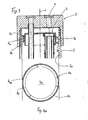
- Fig. 3 shows an enlarged partial section of the swirl separator 7 and its arrangement in the container 2, which has a cylindrical inner wall 2a and a cylinder axis a.
- the outer edges of the guide surfaces 8a, 8b, 8c have no contact with the inner wall 2a, but between them an annular gap 9 is left, which in Fig.
- baffles 8 may have a circumferential or coverage angle in the range of 180 ° to 400 °, preferably 270 ° to 360 °.
- the choice of this ratio V is decisive for the formation of the flow at the swirl separator 7 and thus for the separation of gaseous and liquid phase of the refrigerant, ie ultimately for the steam quality of the exiting refrigerant.
- the function of the liquid separator 7 according to the invention or of the so-called swirl separator 7 is described below:
- the refrigerant which is in the vaporous and liquid phase, enters the collector 1 through the inlet 4 and then strikes the impact surface 7a of the swirl separator 7, where liquid portions adhere to the baffle surface 7a and flow outward in a radially directed flow until they strike the baffles 8a, 8b, 8c.
- the helically arranged guide surfaces 8a, 8b, 8c impose a swirling flow on the refrigerant flow, which exerts a centrifugal force effect on the liquid portions and urges them outward into the annular gap 9.
- a bypass flow of the refrigerant which is oriented essentially in the direction of the cylinder axis a, is formed, which receives the liquid portions thrown outward from the guide surfaces 8a, 8b, 8c and transports them to the lower region of the container.
- the characteristic of the swirl separator 7 is that on the one hand a swirl flow in the channel cross-sections between the guide surfaces 8a, 8b, 8c and on the other hand form a bypass flow in the annular gap 9.
- the centrifugal force is used for the separation of liquid components of the refrigerant and, on the other hand, the bypass flow achieves a faster effective removal with a low pressure drop.
Landscapes
- Engineering & Computer Science (AREA)
- Chemical & Material Sciences (AREA)
- Analytical Chemistry (AREA)
- Power Engineering (AREA)
- Physics & Mathematics (AREA)
- Mechanical Engineering (AREA)
- Thermal Sciences (AREA)
- General Engineering & Computer Science (AREA)
- Air-Conditioning For Vehicles (AREA)
- Cyclones (AREA)
Abstract
Description
- Die Erfindung betrifft einen Kältemittelsammler mit Flüssigkeitsabscheider nach dem Oberbegriff des Patentanspruches 1.
- Kältemittelsammler, auch Kältemittelakkumulatoren genannt, für Kältemittelkreisläufe sind bekannt: Der Kältemittelsammler, im Folgenden auch kurz Sammler genannt, ist hinter einem Verdampfer des Kältemittelkreislaufes angeordnet und hat die Aufgabe, die gasförmige und die flüssige Phase des eintretenden Kältemittels voneinander zu trennen und das flüssige Kältemittel zu speichern. Der Sammler dient somit auch als Volumenpuffer- Das aus dem Sammler abgesaugte Kältemittel, welches einem nachgeschalteten Kompressor des Kältemittelkreislaufes zugeführt wird, soll einen möglichst hohen Dampfgehaft, d. h. einen hohen Anteil an gasförmiger Phase aufweisen. Ferner hat der Sammler die Aufgabe, vom Verdichter in den Kältemittelkreislauf eingebrachtes Verdichterschmier- bzw. Kältemittelöl, welches zwangsläufig zusammen mit dem Kältemittel abgeschieden wird, zum Verdichter zurückzuführen.
- Durch die
DE 10 2005 059 482 A1 wurde ein Kältemittelsammler mit einem Flüssigkeitsabscheider bekannt, welcher als glockenförmiges Prallblech ausgebildet und oberhalb des Eintrittes eines Saugrohres angeordnet ist. Das Prallblech schirmt somit den Eintritt des Saugrohres gegenüber dem in den Sammler einströmenden Kältemittel ab und verhindert eine "Kurzschlussströmung" zum Auslass des Sammlers. - Bekannt ist es auch, einen Kältemittelsammler mit einem inneren Wärmeübertrager zu einer Baueinheit zu integrieren, welche in der
DE 10 2006 031 197 A1 offenbart ist. - Durch die
US 4,651,540 A wurde ein Kältemittelsammler mit einem Flüssigkeitsabscheider bekannt, welcher auf seiner Oberseite einen spiralförmig ausgebildeten Kanal aufweist, durch welchen der eintretenden Kältemittelströmung eine tangentiale Strömungsrichtung erteilt wird. Nach Austritt aus dem spiralförmigen Kanal trifft die Kältemittelströmung auf die Behälterinnenwand und strömt über einen Ringspalt in den unteren Bereich des Behälters, wo sich die flüssige Phase des Kältemittels sammelt. - Durch die
DE 103 00 801 B3 wurde ein Kältemittelsammler mit einem Flüssigkeitsabscheider bekannt, welcher eine spiralige Führungsfläche aufweist, welche dem zuströmenden Kältemittel eine Wirbel-Strömungskomponente, d. h. einen Drall erteilt, wodurch das Kältemittel aufgrund von Zentrifugalkräften in flüssige und gasförmige Phasen getrennt werden soll. Nach Austritt aus dem umfangssetiig geschlossenen spiralförmigen Kanal trifft das flüssige Kältemittel auf die Innenwand des Behälters, an welcher es nach unten abläuft. - Es ist Aufgabe der vorliegenden Erfindung, einen Kältemittelsammler der eingangs genannten Art derart zu gestalten, dass ein möglichst hoher Abscheidegrad, d. h. ein möglichst hoher dampfförmiger Anteil für das aus dem Sammler austretende Kältemittel erreicht wird.
- Die Aufgabe der Erfindung wird durch die Merkmale des Patentanspruches 1 gelöst. Vorteilhafte Ausgestaltungen ergeben sich aus den Unteransprüchen.
- Erfindungsgemäß weist der Flüssigkeitsabscheider, angrenzend an eine Pralffläche, eine Mantelfläche auf, auf der schraubenlinienförmig verlaufende Leitflächen angeordnet sind. Dabei sind die Leitflächen mindestens zweigängig, vorzugsweise freigängig - nach Art eines Bewegungsgewindes - auf der Mantelfläche angeordnet. Die in den Sammler eintretende, in flüssiger und gasförmiger Phase vorliegende Kältemittelströmung trifft zunächst auf die Prallfläche des Flüssigkeitsabscheiders, wo ein Anhaften der Flüssiganteile des Kältemittels und ein radial gerichtetes Abströmen bis zur Kante des Flüssigkeitsabscheiders erfolgen. Danach trifft das Kältemittel auf die schraubenförmigen Leitflächen, wodurch dem Kältemittel eine Drallströmung aufgezwungen wird, mit der Folge, dass die Flüssigkeitsteilchen im Kältemittel aufgrund von Zentrifugalkräften nach außen, d. h. an die Behälterinnenwand gedrängt werden. Damit wird der Vorteil einer wirksamen Trennung von flüssiger und gasförmiger Phase des Kältemittels erreicht, was zu einem hohen Dampfgehalt für das austretende Kältemittel führt.
- Nach einer besonders vorteilhaften Ausführungsform ist zwischen der Mantelfläche mit Leitflächen und der Innenwand des Behälters ein Ringspalt belassen, d. h. die Außenkanten der schraubenlinienförmig verlaufenden Leitflächen liegen nicht an der Innenwandung des Behälters an, vielmehr wird die Gesamtdurchtrittsquerschnittfläche erweitert und damit die Strömungsgeschwindigkeit reduziert, wodurch die Strömung beruhigt wird, d. h. es tritt weniger Turbulenz auf. Damit wird der Vorteil erreicht, dass sich zusätzlich zu der durch die Leitflächen erzeugten drallförmigen Kanalströmung eine Bypassströmung ausbildet, welche vorwiegend vertikal bzw. in Axialrichtung des Behälters ausgerichtet ist. Die Bypassströmung bildet somit einen "Flüssigkeits-Vorhang" zwischen den Leitflächen und der Behälterinnenwand, was den Vorteil mit sich bringt, dass die aufgrund der Drallströmung nach außen geförderten Flüssigkeitsteilchen sofort von der nach unten gerichteten Bypassströmung mitgerissen werden. Damit wird die Abscheidung der flüssigen Phase des Kältemittels entscheidend verbessert. Darüber hinaus ergibt sich als Vorteil ein relativ geringer Druckabfall für das durch den Sammler strömende Kältemittel, was sich günstig auf die Antriebsleistung des Kompressors auswirkt. Ferner wird ein stabilerer Dampfgehalt am Kältemittelauslass, d. h. mit geringeren Schwankungen erreicht, wodurch auch der Wirkungsgrad der Anlage geringeren Schwankungen unterworfen ist.
- Nach einer weiteren vorteilhaften Ausführungsform ist vorgesehen, dass der Ringspalt eine Spaltweite von 0.5 bis 3 mm aufweist. Vorteilhaft ist ferner, wenn der Ringspalt eine Querschnitts- oder Durchtrittsfläche im Bereich von 100 bis 400 mm2, vorzugsweise im Bereich von 200 bis 300 mm2 aufweist.
- Damit wird der Vorteil erreicht, dass zusätzlich zu der über die Leitflächen erzeugten Drallströmung eine deutliche Bypassströmung ermöglicht wird, welche die nach außen gedrängten Flüssigkeitsteilchen mitnimmt und am Boden des Behälters abscheidet.
- Besonders vorteilhaft für die Wirkungsweise des erfindungsgemäßen Flüssigkeitsabscheiders ist es, wenn ein definiertes Verhältnis zwischen dem Bypassquerschnitt, d. h. der Ringspaltquerschnittsfläche und dem Gesamtkanalquerschnitt, der sich aus der Summe der Einzelkanalquerschnitte zusammensetzt, eingehalten wird. Dieses Verhältnis liegt im Bereich von 2 bis 4 und beträgt vorzugsweise 3, d. h. die Ringspaltfläche beträgt im bevorzugten Fall das Dreifache der Gesamtkanalquerschnittsfläche des Abscheiders. Damit werden eine besonders wirksame Flüssigkeitsabscheidung bei relativ geringem Druckabfall für das Kältemittel und eine hohe Dampfqualität erreicht.
- In weiterer vorteilhafter Ausgestaltung ist im Behälter ein Saugrohr angeordnet, welches vorzugsweise U-förmig ausgebildet ist und ausgangsseitig durch die Prallfläche des Flüssigkeitsabscheiders geführt ist, während der Eingang des Saugrohres durch die Prallfläche gegenüber dem Behältereinlass abgeschirmt ist. Damit wird eine Kurzschlussströmung zwischen Kältemitteleinlass und -auslass verhindert.
- Nach einer weiteren bevorzugten Ausführungsform ist der Kältemittelsammler mit erfindungsgemäßem Flüssigkeitsabscheider mit einem inneren Wärmeübertrager des Kältemittelkreislaufes zu einer Baueinheit, einer so genannten Kombieinheit integriert. Damit ergibt sich eine kompakte Bauweise von zwei Komponenten des Kältemittelkreislaufes, verbunden mit einer thermischen Kopplung zwischen der Niederdruckseite und der Hochdruckseite des Kältemittelkreislaufes.
- Ein Ausführungsbeispiel der Erfindung ist in der Zeichnung dargestellt und wird im Folgenden näher beschrieben, wobei sich auch weitere Merkmale und Vorteile ergeben. Es zeigen
- Fig. 1
- einen Längsschnitt durch einen Kältemittelsammler mit erfindungs-gemäßem Flüssigkeitsabscheider,
- Fig. 2
- einen Längsschnitt des Behälters gemäß
Fig. 1 in perspektivischer Darstellung, - Fig. 3
- die Anordnung des erfindungsgemäßen Flüssigkeitsabscheiders in einem vergrößerten Teilschnitt und
- Fig. 3a
- eine Ansicht von oben auf den Flüssigkeitsabscheider.
-
Fig. 1 zeigt einen Kältemittelsammler 1, auch Kältemittelakkumulator oder kurz Sammler genannt, für einen nicht dargestellten Kältemittelkreislauf, vorzugsweise einen mit CO2 bzw. R744 betriebenen Käftemittelkreislauf für eine Kraftfahrzeugklimaanlage. Der Sammler 1 weist einen kreiszylindrischen Behälter 2 auf, der durch einen Deckel 3 kältemitteldicht und druckfest verschlossen ist. Der Deckel 3 ist als Kältemittelanschlussflansch ausgebildet und weist eine Eingangsöffnung 4, welche stromabwärts von einem nicht dargestellten Verdampfer des Kältemittelkreislaufes angeordnet ist, und eine Ausgangsöffnung 5 auf, welche stromaufwärts in Richtung eines nicht dargestellten Kompressors angeordnet ist. Innerhalb des Behälters 2 ist ein U-förmig ausgebildetes Saugrohr 6 angeordnet, welches ein eingangsseitiges Ende 6a, ein ausgangsseitiges Ende 6b sowie einen bogenförmigen Bereich 6c aufweist. Im oberen Bereich des Behälters 2 und unterhalb der Eingangsöffnung 4 ist ein Flüssigkeitsabscheider 7 angeordnet, welcher etwa topfförmig ausgebildet ist und auf seinem Umfang schraubenlinienförmig ausgebildete Leitflächen 8 aufweist. Zwischen dem Flüssigkeitsabscheider 7, im Folgenden auch kurz Drallabscheider 7 genannt, ist ein Ringspalt 9 belassen, auf welchen unten genauer eingegangen wird. Das eingangsseitige Ende 6a ist innerhalb des topfförmigen Drallabscheiders 7 angeordnet und wird von einem Gasfilter 10 umschlossen. Das eingangsseitige Ende 6a des Saugrohres 6 ist somit durch den Drallabscheider 7 gegenüber dem durch die Eingangsöffnung 4 einströmenden Kältemittel abgeschirmt. Das ausgangsseitige Ende 6b ist druck- und kältemitteldicht mit dem Deckel 3 im Bereich der Austrittsöffnung 5 verbunden, vorzugsweise durch Einwalzen in die Wandung der Bohrung 5. Im bogenförmigen Bereich 6c des Saugrohres 6 ist ein Ölfilter 11 angeordnet, über welches aus dem Kältemittel abgeschiedenes Verdichterschmiermittel abgesaugt und Schmutzpartikel zurückgehalten werden. -
Fig. 2 zeigt den aufgeschnittenen Sammler 1 in einer perspektivischen Darstellung mit einer Außenansicht des Drallkörpers 7, welcher eine eben ausgebildete Drallfläche 7a und eine zylindrische Mantelfläche 7b aufweist, von welcher drei schraubenlinienförmig ausgebildete Leitflächen 8a, 8b, 8c abragen. Die Leitflächen 3a bilden quasi ein dreigängiges Bewegungsgewinde, wobei die Anordnung der Leitflächen auch zwei oder viergängig ausgebildet sein kann. -
Fig. 3 zeigt einen vergrößerten Teilschnitt des Drallabscheiders 7 und seine Anordnung im Behälter 2, welcher eine zylindrische Innenwand 2a und eine Zylinderachse a aufweist. Zwischen zwei benachbarten Leitflächen 8a, 8b, welche senkrecht von der Mantelfläche 7b abragen, ist ein schraffiert dargestellter Einzelkanalquerschnitt mit der Durchtrittsfläche AK gebildet. Da die Leitflächen 8a, 8b, 8c dreigängig angeordnet sind, ergibt sich ein Gesamtkanalquerschnitt AKges = 3 AK. Wie aus der Zeichnung ersichtlich, haben die Außenkanten der Leitflächen 8a, 8b, 8c keinen Kontakt mit der Innenwand 2a, vielmehr ist zwischen diesen ein Ringspalt 9 belassen, welcher inFig. 3a , d. h. in einer Ansicht von oben als schraffierte Kreisringfläche ARS dargestellt ist. Man erkennt ferner ausFig. 3a die in Umfangsrichtung versetzte Anordnung der drei Leitflächen 8a, 8b, 8c, welche jeweils um 120° gegeneinander versetzt sind. Die Leitflächen 8 können einen Umfangs- oder Überdeckungswinkel im Bereich von 180° bis 400°, vorzugsweise von 270° bis 360° aufweisen. - Nach einer bevorzugten Ausführungsform ist ein Verhältnis V von Ringspaltfläche ARS zu Gesamtkanalfläche AKges definiert, welches in einem Bereich von 2 ≤ V ≤ 4 gewählt ist, vorzugsweise ist ein Wert von V = 3 vorgesehen. Die Wahl dieses Verhältnisses V ist maßgebend für die Ausbildung der Strömung am Drallabscheider 7 und damit für die Trennung von gasförmiger und flüssiger Phase des Kältemittels, d. h. letztendlich für die Dampfqualität des austretenden Kältemittels.
- Die Funktion des erfindungsgemäßen Flüssigkeitsabscheiders 7 oder des so genannten Drallabscheiders 7 wird im Folgenden beschrieben: Das Kältemittel, welches in dampfförmiger und flüssiger Phase vorliegt, tritt durch den Eingang 4 in den Sammler 1 ein und trifft dann zunächst auf die Prallfläche 7a des Drallabscheiders 7, wo flüssige Anteile an der Prallfläche 7a anhaften und in einer radial gerichteten Strömung nach außen fließen, bis sie auf die Leitflächen 8a, 8b, 8c treffen. Die schraubenförmig angeordneten Leitflächen 8a, 8b, 8c prägen der Kältemittelströmung eine Drallströmung auf, welche eine Fliehkraftwirkung auf die Flüssiganteile ausübt und diese nach außen in den Ringspalt 9 drängt. Im Ringspalt 9 bildet sich eine im Wesentlichen in Richtung der Zylinderachse a ausgerichtete Bypassströmung des Kältemittels aus, welche die von den Leitflächen 8a, 8b, 8c nach außen geschleuderten Flüssiganteile aufnimmt und in den unteren Bereich des Behälters transportiert. Das Charakteristische des Drallabscheiders 7 besteht darin, dass sich einerseits eine Drallströmung in den Kanalquerschnitten zwischen den Leitflächen 8a, 8b, 8c und andererseits eine Bypassströmung im Ringspalt 9 ausbilden. Damit wird einerseits die Fliehkraft zur Abscheidung von Flüssiganteilen des Kältemittel genutzt und andererseits durch die Bypassströmung ein schneller wirksamer Abtransport bei geringem Druckabfall erzielt. Maßgeblich für die Wirksamkeit ist die Einstellung der Strömungsverhältnisse in den Kanalquerschnitten und in dem Ringspaltquerschnitt, wobei sich die oben erwähnten Verhältnisse aufgrund von Messungen der Anmelderin als vorteilhaft erwiesen haben. Darüber hinaus erfolgt durch die Querschnittserweiterung infolge des Ringspaltes eine Beruhigung der Kältemittelströmung, die zu geringeren Turbulenzen führt, wodurch .der Abscheidewirkungsgrad erhöht wird. Das flüssige Kältemittel sinkt im Behälter 2 nach unten und sammelt sich im unteren Bereich. Über dem Kältemittelspiegel befindet sich die gasförmige Phase, welche über das eingangsseitige Ende 6a, vgl. insbesondere
Fig. 1 mit Pfeil, nach Filterung durch den Gasfilter 10 angesaugt und über das ausgangsseitige Ende 6b des Saugrohres 6 am Ausgang 5 abgesaugt wird. - Messungen der Anmelderin haben gezeigt, dass sich mit dem erfindungsgemäßen Drallabscheider 7 hohe Dampfqualitäten, d. h. Gasanteile von über 90 % dauerhaft, d. h. bei unterschiedlichen Betriebszuständen der Klimaanlage im Kraftfahrzeug erreichen lassen. Insbesondere haben diese Messungen annähernd konstante, d. h. stabile Dampfgehalte von Ober 90 % bei unterschiedlichen flüssigen Kältemittelmengen im Sammler 1 ergeben. Beim Stand der Technik besteht dagegen das Problem, dass die Dampfqualität mit zunehmendem Füllstand des flüssigen Kältemittels im Sammler abnimmt. Dieser Nachteil wird durch die Erfindung vermieden.
Claims (10)
- Kältemittelsammler (1) mit Flüssigkeitsabscheider (7) für einen Kältemittelkreislauf, insbesondere für Kraftfahrzeugklimaanlagen, wobei der Käitemittelsammler (1) einen Behälter (2) zur Aufnahme des Kältemittels sowie einen Kältemitteleinlass (4) und einen Kältemittelauslass (5) aufweist, dadurch gekennzeichnet, dass der Flüssigkeitsabscheider (7) eine Prallfläche (7a) und eine Mantelfläche (7b) aufweist, auf welcher mindestens zwei schraubenlinienförmig verlaufende Leitflächen (8) angeordnet sind.
- Kältemittelsammler nach Anspruch 1, dadurch gekennzeichnet, dass die Leitflächen (8) als dreigängige Schraubenflächen (8a, 8b, 8c) ausgebildet sind.
- Kältemittelsammler nach Anspruch 1 oder 2, dadurch gekennzeichnet, dass die Leitflächen (8a, 8b, 8c) radial von der Mantelfläche (7b) abragen und einen Außendurchmesser aufweisen, dass der Behälter (2) eine zylindrische Innenwand (2a) mit einem Innendurchmesser aufweist und dass zwischen dem Innen- und dem Außendurchmesser ein Ringspalt (9) belassen ist.
- Kältemittelsammler nach Anspruch 1, 2 oder 3, dadurch gekennzeichnet, dass sich die Leitflächen (8a, 8b, 8c) über einen Umfangswinkel im Bereich von 180° bis 400°, vorzugsweise in einem Bereich von 270° bis 360° erstrecken.
- Kältemittelsammler nach Anspruch 3, dadurch gekennzeichnet, dass der Ringspalt (9) eine Spaltbreite aufweist, die im Bereich von 0,5 bis 3 mm liegt.
- Kältemittelsammler nach Anspruch 3, 4 oder 5, dadurch gekennzeichnet, dass der Ringspalt (9) eine Querschnitts- oder Durchtrittsfläche (ARS) im Bereich von 100 bis 400 mm2, vorzugsweise im Bereich von 200 bis 300 mm2 aufweist.
- Kältemittelsammler nach Anspruch 6, dadurch gekennzeichnet, dass die Leitflächen (8a, 8b, 8c) einen Einzelkanalquerschnitt mit der Durchtrittsfläche (AK) und einen Gesamtkanalquerschnitt mit der Durchtrittsfläche (AKges) bilden, und dass das Verhältnis V von Ringspaltquerschnittsfiäche (ARS) zu Gesamtkanalquerschnittsfläche (AK- ges) im Bereich von 2 ≤ V ≤ 4, insbesondere bei V = 3 liegt.
- Kältemittelsammler nach einem der vorhergehenden Ansprüche, dadurch gekennzeichnet, dass innerhalb des Sammlers (1) ein Saugrohr (6) angeordnet ist, dessen ausgangsseitiges Ende (6b) mit dem Kältemittelauslass (5) verbunden ist.
- Kältemittelsammler nach Anspruch 8, dadurch gekennzeichnet, dass das Saugrohr (6) U-förmig ausgebildet ist und ein einlassseitiges Ende (6a) aufweist, welches durch die Prallfläche (7a) abgedeckt ist.
- Kältemittelsammler nach einem der vorhergehenden Ansprüche, dadurch gekennzeichnet dass er mit einem inneren Wärmeübertrager des Kältemittelkreislaufes zu einer Baueinheit, einer so genannten Kombieinheit integriert ist.
Applications Claiming Priority (1)
| Application Number | Priority Date | Filing Date | Title |
|---|---|---|---|
| DE102008028852A DE102008028852A1 (de) | 2008-06-19 | 2008-06-19 | Kältemittelsammler mit Flüssigkeitsabscheider |
Publications (2)
| Publication Number | Publication Date |
|---|---|
| EP2136163A1 true EP2136163A1 (de) | 2009-12-23 |
| EP2136163B1 EP2136163B1 (de) | 2012-08-15 |
Family
ID=41055238
Family Applications (1)
| Application Number | Title | Priority Date | Filing Date |
|---|---|---|---|
| EP20090007514 Active EP2136163B1 (de) | 2008-06-19 | 2009-06-08 | Kältemittelsammler mit Flüssigkeitsabscheider |
Country Status (2)
| Country | Link |
|---|---|
| EP (1) | EP2136163B1 (de) |
| DE (1) | DE102008028852A1 (de) |
Cited By (5)
| Publication number | Priority date | Publication date | Assignee | Title |
|---|---|---|---|---|
| JP2012132608A (ja) * | 2010-12-21 | 2012-07-12 | Calsonic Kansei Corp | アキュムレータ |
| JP2012233664A (ja) * | 2011-05-09 | 2012-11-29 | Calsonic Kansei Corp | アキュムレータ |
| CN108759203A (zh) * | 2018-08-03 | 2018-11-06 | 蚌埠市昊源压缩机制造有限公司 | 一种用于压缩机的气液分离器 |
| WO2019107011A1 (ja) * | 2017-12-01 | 2019-06-06 | 株式会社不二工機 | アキュームレータ |
| CN111442581A (zh) * | 2020-05-14 | 2020-07-24 | 和龙双昊高新技术有限公司 | 一种带余热回收功能的汽车空调用气液分离器 |
Families Citing this family (4)
| Publication number | Priority date | Publication date | Assignee | Title |
|---|---|---|---|---|
| DE102015207808A1 (de) | 2014-04-29 | 2015-10-29 | Mahle International Gmbh | Volumenausgleichsvorrichtung |
| DE102014220401A1 (de) | 2014-10-08 | 2016-04-14 | Mahle International Gmbh | Kältemittelbehälter für eine Kälteanlage |
| IT201900003469A1 (it) * | 2019-03-12 | 2020-09-12 | Techinvest S R L | Ciclocondensatore |
| WO2023128458A1 (ko) * | 2021-12-31 | 2023-07-06 | 한온시스템 주식회사 | 차량용 어큐뮬레이터 |
Citations (8)
| Publication number | Priority date | Publication date | Assignee | Title |
|---|---|---|---|---|
| US4182136A (en) * | 1977-12-22 | 1980-01-08 | Tecumseh Products Company | Suction accumulator |
| US4651540A (en) | 1986-03-21 | 1987-03-24 | Tecumseh Products Company | Suction accumulator including an entrance baffle |
| JPH04366377A (ja) * | 1991-06-11 | 1992-12-18 | Daikin Ind Ltd | 気液分離器 |
| US6167720B1 (en) * | 1999-10-19 | 2001-01-02 | Automotive Fluid Systems, Inc. | Accumulator baffle molded from desiccant |
| US20020095948A1 (en) * | 2001-01-22 | 2002-07-25 | Corrigan Daniel Leonard | Suction accumulator for air conditioning systems |
| DE10300801B3 (de) | 2003-01-13 | 2004-06-24 | Hansa Metallwerke Ag | Akkumulator für eine Klimaanlage, insbesondere Fahrzeugklimaanlage |
| DE102005059482A1 (de) | 2005-12-07 | 2007-06-14 | Visteon Global Technologies, Inc., Van Buren | Kältemittelakkumulator mit Flüssigkeitsabscheider |
| US20080000261A1 (en) * | 2006-07-03 | 2008-01-03 | Thomas Klotten | Internal heat exchanger |
Family Cites Families (4)
| Publication number | Priority date | Publication date | Assignee | Title |
|---|---|---|---|---|
| US5746065A (en) * | 1996-08-21 | 1998-05-05 | Automotive Fluid Systems, Inc. | Accumulator deflector connection and method |
| DE19808893A1 (de) * | 1998-03-03 | 1999-09-09 | Behr Gmbh & Co | Wärmeübertragereinheit und diese enthaltende Sammler-Wärmeübertrager-Baueinheit |
| IT1312193B1 (it) * | 1999-04-20 | 2002-04-09 | Bundy Kmp S R L | Accumulatore disidratatore per circuiti di refrigerazione e suoprocedimento di assiemaggio |
| US6523365B2 (en) * | 2000-12-29 | 2003-02-25 | Visteon Global Technologies, Inc. | Accumulator with internal heat exchanger |
-
2008
- 2008-06-19 DE DE102008028852A patent/DE102008028852A1/de not_active Withdrawn
-
2009
- 2009-06-08 EP EP20090007514 patent/EP2136163B1/de active Active
Patent Citations (10)
| Publication number | Priority date | Publication date | Assignee | Title |
|---|---|---|---|---|
| US4182136A (en) * | 1977-12-22 | 1980-01-08 | Tecumseh Products Company | Suction accumulator |
| US4651540A (en) | 1986-03-21 | 1987-03-24 | Tecumseh Products Company | Suction accumulator including an entrance baffle |
| JPH04366377A (ja) * | 1991-06-11 | 1992-12-18 | Daikin Ind Ltd | 気液分離器 |
| US6167720B1 (en) * | 1999-10-19 | 2001-01-02 | Automotive Fluid Systems, Inc. | Accumulator baffle molded from desiccant |
| US20020095948A1 (en) * | 2001-01-22 | 2002-07-25 | Corrigan Daniel Leonard | Suction accumulator for air conditioning systems |
| DE10300801B3 (de) | 2003-01-13 | 2004-06-24 | Hansa Metallwerke Ag | Akkumulator für eine Klimaanlage, insbesondere Fahrzeugklimaanlage |
| EP1437563A2 (de) * | 2003-01-13 | 2004-07-14 | Hansa Metallwerke Ag | Akkumulator für eine Klimaanlage, insbesondere Fahrzeugklimaanlage |
| DE102005059482A1 (de) | 2005-12-07 | 2007-06-14 | Visteon Global Technologies, Inc., Van Buren | Kältemittelakkumulator mit Flüssigkeitsabscheider |
| US20080000261A1 (en) * | 2006-07-03 | 2008-01-03 | Thomas Klotten | Internal heat exchanger |
| DE102006031197A1 (de) | 2006-07-03 | 2008-01-10 | Visteon Global Technologies Inc., Van Buren | Innerer Wärmeübertrager mit Akkumulator |
Cited By (6)
| Publication number | Priority date | Publication date | Assignee | Title |
|---|---|---|---|---|
| JP2012132608A (ja) * | 2010-12-21 | 2012-07-12 | Calsonic Kansei Corp | アキュムレータ |
| JP2012233664A (ja) * | 2011-05-09 | 2012-11-29 | Calsonic Kansei Corp | アキュムレータ |
| WO2019107011A1 (ja) * | 2017-12-01 | 2019-06-06 | 株式会社不二工機 | アキュームレータ |
| JP2019100624A (ja) * | 2017-12-01 | 2019-06-24 | 株式会社不二工機 | アキュームレータ |
| CN108759203A (zh) * | 2018-08-03 | 2018-11-06 | 蚌埠市昊源压缩机制造有限公司 | 一种用于压缩机的气液分离器 |
| CN111442581A (zh) * | 2020-05-14 | 2020-07-24 | 和龙双昊高新技术有限公司 | 一种带余热回收功能的汽车空调用气液分离器 |
Also Published As
| Publication number | Publication date |
|---|---|
| DE102008028852A1 (de) | 2009-12-24 |
| EP2136163B1 (de) | 2012-08-15 |
Similar Documents
| Publication | Publication Date | Title |
|---|---|---|
| EP2136163B1 (de) | Kältemittelsammler mit Flüssigkeitsabscheider | |
| EP2276577B1 (de) | Abscheider für eine kurbelgehäuseentlüftung einer brennkraftmaschine | |
| EP1167743B1 (de) | Ansaugsystem mit Wasserabscheider | |
| DE102011122322A1 (de) | Fliehkraftabscheider und Filteranordnung | |
| DE2818791A1 (de) | Wirbelrohr fuer zyklonabscheider | |
| DE10335194A1 (de) | Staub-Vorabscheider für einen Kraftfahrzeugmotor | |
| EP2378225B1 (de) | Kondensator für eine Klimaanlage, insbesondere eines Kraftfahrzeuges | |
| DE102014113128A1 (de) | Tankvorrichtung eines Flugtriebwerks mit einer Einrichtung zum Einleiten von Öl | |
| DE69006551T2 (de) | Auf einen Verdichter befestigter, mit diesem eine bauliche Einheit bildender Ölabscheider. | |
| DE102018211300A1 (de) | Kondensatabscheider | |
| DE202020005600U1 (de) | Zyklonabscheider | |
| CH470637A (de) | Gerät zum Abscheiden eines flüssigen und/oder dampfförmigen Mediums aus einem Trägergas und dessen Verwendung in Flugzeugen | |
| DE4040142C2 (de) | ||
| WO2007110284A1 (de) | Abscheidevorrichtung zum abscheiden von teilchen | |
| DE19650359A1 (de) | Abscheider zum Abscheiden von Flüssigkeiten, insbesondere von Schadstoffen, aus einem Gasstrom | |
| WO2019145133A1 (de) | Filtergehäuse für eine filtereinrichtung | |
| EP2423496B1 (de) | Zyklonabscheider mit horizontaler Zyklonachse | |
| DE202017007339U1 (de) | Abscheidesystem | |
| WO2006077021A1 (de) | Abscheidevorrichtung zum abscheiden von flüssigkeitspartikeln aus einem gasförmigen medium | |
| DE3107607A1 (de) | Filter mit feststehendem siebeinsatz insbesondere fuer industriewasser | |
| DE102011056903B4 (de) | Hubkolbenverdichter und Verfahren zum Abscheiden von Flüssigkeiten, insbesondere Öl | |
| DE102019109302A1 (de) | Verdichter | |
| DE102010037206A1 (de) | Wärmetauscher | |
| DE2856002C2 (de) | ||
| DE10300801B3 (de) | Akkumulator für eine Klimaanlage, insbesondere Fahrzeugklimaanlage |
Legal Events
| Date | Code | Title | Description |
|---|---|---|---|
| PUAI | Public reference made under article 153(3) epc to a published international application that has entered the european phase |
Free format text: ORIGINAL CODE: 0009012 |
|
| AK | Designated contracting states |
Kind code of ref document: A1 Designated state(s): AT BE BG CH CY CZ DE DK EE ES FI FR GB GR HR HU IE IS IT LI LT LU LV MC MK MT NL NO PL PT RO SE SI SK TR |
|
| 17P | Request for examination filed |
Effective date: 20100420 |
|
| 17Q | First examination report despatched |
Effective date: 20100803 |
|
| GRAP | Despatch of communication of intention to grant a patent |
Free format text: ORIGINAL CODE: EPIDOSNIGR1 |
|
| GRAS | Grant fee paid |
Free format text: ORIGINAL CODE: EPIDOSNIGR3 |
|
| GRAA | (expected) grant |
Free format text: ORIGINAL CODE: 0009210 |
|
| AK | Designated contracting states |
Kind code of ref document: B1 Designated state(s): AT BE BG CH CY CZ DE DK EE ES FI FR GB GR HR HU IE IS IT LI LT LU LV MC MK MT NL NO PL PT RO SE SI SK TR |
|
| REG | Reference to a national code |
Ref country code: GB Ref legal event code: FG4D Free format text: NOT ENGLISH Ref country code: CH Ref legal event code: EP Ref country code: AT Ref legal event code: REF Ref document number: 571056 Country of ref document: AT Kind code of ref document: T Effective date: 20120815 |
|
| REG | Reference to a national code |
Ref country code: IE Ref legal event code: FG4D Free format text: LANGUAGE OF EP DOCUMENT: GERMAN |
|
| REG | Reference to a national code |
Ref country code: DE Ref legal event code: R096 Ref document number: 502009004375 Country of ref document: DE Effective date: 20121011 |
|
| REG | Reference to a national code |
Ref country code: NL Ref legal event code: VDEP Effective date: 20120815 |
|
| PG25 | Lapsed in a contracting state [announced via postgrant information from national office to epo] |
Ref country code: LT Free format text: LAPSE BECAUSE OF FAILURE TO SUBMIT A TRANSLATION OF THE DESCRIPTION OR TO PAY THE FEE WITHIN THE PRESCRIBED TIME-LIMIT Effective date: 20120815 Ref country code: CY Free format text: LAPSE BECAUSE OF FAILURE TO SUBMIT A TRANSLATION OF THE DESCRIPTION OR TO PAY THE FEE WITHIN THE PRESCRIBED TIME-LIMIT Effective date: 20120815 Ref country code: IS Free format text: LAPSE BECAUSE OF FAILURE TO SUBMIT A TRANSLATION OF THE DESCRIPTION OR TO PAY THE FEE WITHIN THE PRESCRIBED TIME-LIMIT Effective date: 20121215 Ref country code: FI Free format text: LAPSE BECAUSE OF FAILURE TO SUBMIT A TRANSLATION OF THE DESCRIPTION OR TO PAY THE FEE WITHIN THE PRESCRIBED TIME-LIMIT Effective date: 20120815 Ref country code: NO Free format text: LAPSE BECAUSE OF FAILURE TO SUBMIT A TRANSLATION OF THE DESCRIPTION OR TO PAY THE FEE WITHIN THE PRESCRIBED TIME-LIMIT Effective date: 20121115 Ref country code: HR Free format text: LAPSE BECAUSE OF FAILURE TO SUBMIT A TRANSLATION OF THE DESCRIPTION OR TO PAY THE FEE WITHIN THE PRESCRIBED TIME-LIMIT Effective date: 20120815 |
|
| PG25 | Lapsed in a contracting state [announced via postgrant information from national office to epo] |
Ref country code: GR Free format text: LAPSE BECAUSE OF FAILURE TO SUBMIT A TRANSLATION OF THE DESCRIPTION OR TO PAY THE FEE WITHIN THE PRESCRIBED TIME-LIMIT Effective date: 20121116 Ref country code: PL Free format text: LAPSE BECAUSE OF FAILURE TO SUBMIT A TRANSLATION OF THE DESCRIPTION OR TO PAY THE FEE WITHIN THE PRESCRIBED TIME-LIMIT Effective date: 20120815 Ref country code: LV Free format text: LAPSE BECAUSE OF FAILURE TO SUBMIT A TRANSLATION OF THE DESCRIPTION OR TO PAY THE FEE WITHIN THE PRESCRIBED TIME-LIMIT Effective date: 20120815 Ref country code: PT Free format text: LAPSE BECAUSE OF FAILURE TO SUBMIT A TRANSLATION OF THE DESCRIPTION OR TO PAY THE FEE WITHIN THE PRESCRIBED TIME-LIMIT Effective date: 20121217 Ref country code: SE Free format text: LAPSE BECAUSE OF FAILURE TO SUBMIT A TRANSLATION OF THE DESCRIPTION OR TO PAY THE FEE WITHIN THE PRESCRIBED TIME-LIMIT Effective date: 20120815 Ref country code: SI Free format text: LAPSE BECAUSE OF FAILURE TO SUBMIT A TRANSLATION OF THE DESCRIPTION OR TO PAY THE FEE WITHIN THE PRESCRIBED TIME-LIMIT Effective date: 20120815 |
|
| PG25 | Lapsed in a contracting state [announced via postgrant information from national office to epo] |
Ref country code: NL Free format text: LAPSE BECAUSE OF FAILURE TO SUBMIT A TRANSLATION OF THE DESCRIPTION OR TO PAY THE FEE WITHIN THE PRESCRIBED TIME-LIMIT Effective date: 20120815 |
|
| PG25 | Lapsed in a contracting state [announced via postgrant information from national office to epo] |
Ref country code: ES Free format text: LAPSE BECAUSE OF FAILURE TO SUBMIT A TRANSLATION OF THE DESCRIPTION OR TO PAY THE FEE WITHIN THE PRESCRIBED TIME-LIMIT Effective date: 20121126 Ref country code: CZ Free format text: LAPSE BECAUSE OF FAILURE TO SUBMIT A TRANSLATION OF THE DESCRIPTION OR TO PAY THE FEE WITHIN THE PRESCRIBED TIME-LIMIT Effective date: 20120815 Ref country code: RO Free format text: LAPSE BECAUSE OF FAILURE TO SUBMIT A TRANSLATION OF THE DESCRIPTION OR TO PAY THE FEE WITHIN THE PRESCRIBED TIME-LIMIT Effective date: 20120815 Ref country code: DK Free format text: LAPSE BECAUSE OF FAILURE TO SUBMIT A TRANSLATION OF THE DESCRIPTION OR TO PAY THE FEE WITHIN THE PRESCRIBED TIME-LIMIT Effective date: 20120815 Ref country code: EE Free format text: LAPSE BECAUSE OF FAILURE TO SUBMIT A TRANSLATION OF THE DESCRIPTION OR TO PAY THE FEE WITHIN THE PRESCRIBED TIME-LIMIT Effective date: 20120815 |
|
| PG25 | Lapsed in a contracting state [announced via postgrant information from national office to epo] |
Ref country code: SK Free format text: LAPSE BECAUSE OF FAILURE TO SUBMIT A TRANSLATION OF THE DESCRIPTION OR TO PAY THE FEE WITHIN THE PRESCRIBED TIME-LIMIT Effective date: 20120815 Ref country code: IT Free format text: LAPSE BECAUSE OF FAILURE TO SUBMIT A TRANSLATION OF THE DESCRIPTION OR TO PAY THE FEE WITHIN THE PRESCRIBED TIME-LIMIT Effective date: 20120815 |
|
| PLBE | No opposition filed within time limit |
Free format text: ORIGINAL CODE: 0009261 |
|
| STAA | Information on the status of an ep patent application or granted ep patent |
Free format text: STATUS: NO OPPOSITION FILED WITHIN TIME LIMIT |
|
| 26N | No opposition filed |
Effective date: 20130516 |
|
| PG25 | Lapsed in a contracting state [announced via postgrant information from national office to epo] |
Ref country code: BG Free format text: LAPSE BECAUSE OF FAILURE TO SUBMIT A TRANSLATION OF THE DESCRIPTION OR TO PAY THE FEE WITHIN THE PRESCRIBED TIME-LIMIT Effective date: 20121115 |
|
| REG | Reference to a national code |
Ref country code: DE Ref legal event code: R097 Ref document number: 502009004375 Country of ref document: DE Effective date: 20130516 |
|
| BERE | Be: lapsed |
Owner name: BEHR G.M.B.H. & CO. KG Effective date: 20130630 |
|
| PG25 | Lapsed in a contracting state [announced via postgrant information from national office to epo] |
Ref country code: MC Free format text: LAPSE BECAUSE OF FAILURE TO SUBMIT A TRANSLATION OF THE DESCRIPTION OR TO PAY THE FEE WITHIN THE PRESCRIBED TIME-LIMIT Effective date: 20120815 |
|
| REG | Reference to a national code |
Ref country code: CH Ref legal event code: PL |
|
| GBPC | Gb: european patent ceased through non-payment of renewal fee |
Effective date: 20130608 |
|
| REG | Reference to a national code |
Ref country code: IE Ref legal event code: MM4A |
|
| REG | Reference to a national code |
Ref country code: FR Ref legal event code: ST Effective date: 20140228 |
|
| PG25 | Lapsed in a contracting state [announced via postgrant information from national office to epo] |
Ref country code: BE Free format text: LAPSE BECAUSE OF NON-PAYMENT OF DUE FEES Effective date: 20130630 |
|
| PG25 | Lapsed in a contracting state [announced via postgrant information from national office to epo] |
Ref country code: LI Free format text: LAPSE BECAUSE OF NON-PAYMENT OF DUE FEES Effective date: 20130630 Ref country code: CH Free format text: LAPSE BECAUSE OF NON-PAYMENT OF DUE FEES Effective date: 20130630 Ref country code: IE Free format text: LAPSE BECAUSE OF NON-PAYMENT OF DUE FEES Effective date: 20130608 Ref country code: GB Free format text: LAPSE BECAUSE OF NON-PAYMENT OF DUE FEES Effective date: 20130608 |
|
| PG25 | Lapsed in a contracting state [announced via postgrant information from national office to epo] |
Ref country code: FR Free format text: LAPSE BECAUSE OF NON-PAYMENT OF DUE FEES Effective date: 20130701 |
|
| PG25 | Lapsed in a contracting state [announced via postgrant information from national office to epo] |
Ref country code: MT Free format text: LAPSE BECAUSE OF FAILURE TO SUBMIT A TRANSLATION OF THE DESCRIPTION OR TO PAY THE FEE WITHIN THE PRESCRIBED TIME-LIMIT Effective date: 20120815 |
|
| REG | Reference to a national code |
Ref country code: DE Ref legal event code: R082 Ref document number: 502009004375 Country of ref document: DE Representative=s name: GRAUEL, ANDREAS, DIPL.-PHYS. DR. RER. NAT., DE |
|
| REG | Reference to a national code |
Ref country code: DE Ref legal event code: R081 Ref document number: 502009004375 Country of ref document: DE Owner name: MAHLE INTERNATIONAL GMBH, DE Free format text: FORMER OWNER: BEHR GMBH & CO. KG, 70469 STUTTGART, DE Effective date: 20150317 Ref country code: DE Ref legal event code: R082 Ref document number: 502009004375 Country of ref document: DE Representative=s name: GRAUEL, ANDREAS, DIPL.-PHYS. DR. RER. NAT., DE Effective date: 20150317 |
|
| PG25 | Lapsed in a contracting state [announced via postgrant information from national office to epo] |
Ref country code: TR Free format text: LAPSE BECAUSE OF FAILURE TO SUBMIT A TRANSLATION OF THE DESCRIPTION OR TO PAY THE FEE WITHIN THE PRESCRIBED TIME-LIMIT Effective date: 20120815 |
|
| PG25 | Lapsed in a contracting state [announced via postgrant information from national office to epo] |
Ref country code: LU Free format text: LAPSE BECAUSE OF NON-PAYMENT OF DUE FEES Effective date: 20130608 Ref country code: MK Free format text: LAPSE BECAUSE OF FAILURE TO SUBMIT A TRANSLATION OF THE DESCRIPTION OR TO PAY THE FEE WITHIN THE PRESCRIBED TIME-LIMIT Effective date: 20120815 Ref country code: HU Free format text: LAPSE BECAUSE OF FAILURE TO SUBMIT A TRANSLATION OF THE DESCRIPTION OR TO PAY THE FEE WITHIN THE PRESCRIBED TIME-LIMIT; INVALID AB INITIO Effective date: 20090608 |
|
| REG | Reference to a national code |
Ref country code: AT Ref legal event code: MM01 Ref document number: 571056 Country of ref document: AT Kind code of ref document: T Effective date: 20140608 |
|
| PG25 | Lapsed in a contracting state [announced via postgrant information from national office to epo] |
Ref country code: AT Free format text: LAPSE BECAUSE OF NON-PAYMENT OF DUE FEES Effective date: 20140608 |
|
| P01 | Opt-out of the competence of the unified patent court (upc) registered |
Effective date: 20240527 |
|
| PGFP | Annual fee paid to national office [announced via postgrant information from national office to epo] |
Ref country code: DE Payment date: 20250618 Year of fee payment: 17 |