EP2136162B1 - Steuerungsverfahren fur Kühlanlage mit hoher Kühlkapazität, insbesondere zur Verarbeitung von Lebensmittelmischungen - Google Patents
Steuerungsverfahren fur Kühlanlage mit hoher Kühlkapazität, insbesondere zur Verarbeitung von Lebensmittelmischungen Download PDFInfo
- Publication number
- EP2136162B1 EP2136162B1 EP09160603.8A EP09160603A EP2136162B1 EP 2136162 B1 EP2136162 B1 EP 2136162B1 EP 09160603 A EP09160603 A EP 09160603A EP 2136162 B1 EP2136162 B1 EP 2136162B1
- Authority
- EP
- European Patent Office
- Prior art keywords
- valve
- cooling
- lamination
- regulation
- value
- Prior art date
- Legal status (The legal status is an assumption and is not a legal conclusion. Google has not performed a legal analysis and makes no representation as to the accuracy of the status listed.)
- Not-in-force
Links
Images




Classifications
-
- F—MECHANICAL ENGINEERING; LIGHTING; HEATING; WEAPONS; BLASTING
- F25—REFRIGERATION OR COOLING; COMBINED HEATING AND REFRIGERATION SYSTEMS; HEAT PUMP SYSTEMS; MANUFACTURE OR STORAGE OF ICE; LIQUEFACTION SOLIDIFICATION OF GASES
- F25B—REFRIGERATION MACHINES, PLANTS OR SYSTEMS; COMBINED HEATING AND REFRIGERATION SYSTEMS; HEAT PUMP SYSTEMS
- F25B41/00—Fluid-circulation arrangements
- F25B41/30—Expansion means; Dispositions thereof
- F25B41/31—Expansion valves
- F25B41/34—Expansion valves with the valve member being actuated by electric means, e.g. by piezoelectric actuators
-
- F—MECHANICAL ENGINEERING; LIGHTING; HEATING; WEAPONS; BLASTING
- F25—REFRIGERATION OR COOLING; COMBINED HEATING AND REFRIGERATION SYSTEMS; HEAT PUMP SYSTEMS; MANUFACTURE OR STORAGE OF ICE; LIQUEFACTION SOLIDIFICATION OF GASES
- F25B—REFRIGERATION MACHINES, PLANTS OR SYSTEMS; COMBINED HEATING AND REFRIGERATION SYSTEMS; HEAT PUMP SYSTEMS
- F25B41/00—Fluid-circulation arrangements
- F25B41/30—Expansion means; Dispositions thereof
- F25B41/31—Expansion valves
- F25B41/34—Expansion valves with the valve member being actuated by electric means, e.g. by piezoelectric actuators
- F25B41/345—Expansion valves with the valve member being actuated by electric means, e.g. by piezoelectric actuators by solenoids
-
- F—MECHANICAL ENGINEERING; LIGHTING; HEATING; WEAPONS; BLASTING
- F25—REFRIGERATION OR COOLING; COMBINED HEATING AND REFRIGERATION SYSTEMS; HEAT PUMP SYSTEMS; MANUFACTURE OR STORAGE OF ICE; LIQUEFACTION SOLIDIFICATION OF GASES
- F25B—REFRIGERATION MACHINES, PLANTS OR SYSTEMS; COMBINED HEATING AND REFRIGERATION SYSTEMS; HEAT PUMP SYSTEMS
- F25B41/00—Fluid-circulation arrangements
- F25B41/30—Expansion means; Dispositions thereof
- F25B41/31—Expansion valves
- F25B41/34—Expansion valves with the valve member being actuated by electric means, e.g. by piezoelectric actuators
- F25B41/35—Expansion valves with the valve member being actuated by electric means, e.g. by piezoelectric actuators by rotary motors, e.g. by stepping motors
-
- F—MECHANICAL ENGINEERING; LIGHTING; HEATING; WEAPONS; BLASTING
- F25—REFRIGERATION OR COOLING; COMBINED HEATING AND REFRIGERATION SYSTEMS; HEAT PUMP SYSTEMS; MANUFACTURE OR STORAGE OF ICE; LIQUEFACTION SOLIDIFICATION OF GASES
- F25B—REFRIGERATION MACHINES, PLANTS OR SYSTEMS; COMBINED HEATING AND REFRIGERATION SYSTEMS; HEAT PUMP SYSTEMS
- F25B2600/00—Control issues
- F25B2600/25—Control of valves
- F25B2600/2513—Expansion valves
-
- F—MECHANICAL ENGINEERING; LIGHTING; HEATING; WEAPONS; BLASTING
- F25—REFRIGERATION OR COOLING; COMBINED HEATING AND REFRIGERATION SYSTEMS; HEAT PUMP SYSTEMS; MANUFACTURE OR STORAGE OF ICE; LIQUEFACTION SOLIDIFICATION OF GASES
- F25B—REFRIGERATION MACHINES, PLANTS OR SYSTEMS; COMBINED HEATING AND REFRIGERATION SYSTEMS; HEAT PUMP SYSTEMS
- F25B2700/00—Sensing or detecting of parameters; Sensors therefor
- F25B2700/19—Pressures
- F25B2700/197—Pressures of the evaporator
-
- F—MECHANICAL ENGINEERING; LIGHTING; HEATING; WEAPONS; BLASTING
- F25—REFRIGERATION OR COOLING; COMBINED HEATING AND REFRIGERATION SYSTEMS; HEAT PUMP SYSTEMS; MANUFACTURE OR STORAGE OF ICE; LIQUEFACTION SOLIDIFICATION OF GASES
- F25B—REFRIGERATION MACHINES, PLANTS OR SYSTEMS; COMBINED HEATING AND REFRIGERATION SYSTEMS; HEAT PUMP SYSTEMS
- F25B2700/00—Sensing or detecting of parameters; Sensors therefor
- F25B2700/21—Temperatures
- F25B2700/2115—Temperatures of a compressor or the drive means therefor
- F25B2700/21151—Temperatures of a compressor or the drive means therefor at the suction side of the compressor
-
- F—MECHANICAL ENGINEERING; LIGHTING; HEATING; WEAPONS; BLASTING
- F25—REFRIGERATION OR COOLING; COMBINED HEATING AND REFRIGERATION SYSTEMS; HEAT PUMP SYSTEMS; MANUFACTURE OR STORAGE OF ICE; LIQUEFACTION SOLIDIFICATION OF GASES
- F25D—REFRIGERATORS; COLD ROOMS; ICE-BOXES; COOLING OR FREEZING APPARATUS NOT OTHERWISE PROVIDED FOR
- F25D2700/00—Means for sensing or measuring; Sensors therefor
- F25D2700/16—Sensors measuring the temperature of products
-
- Y—GENERAL TAGGING OF NEW TECHNOLOGICAL DEVELOPMENTS; GENERAL TAGGING OF CROSS-SECTIONAL TECHNOLOGIES SPANNING OVER SEVERAL SECTIONS OF THE IPC; TECHNICAL SUBJECTS COVERED BY FORMER USPC CROSS-REFERENCE ART COLLECTIONS [XRACs] AND DIGESTS
- Y02—TECHNOLOGIES OR APPLICATIONS FOR MITIGATION OR ADAPTATION AGAINST CLIMATE CHANGE
- Y02B—CLIMATE CHANGE MITIGATION TECHNOLOGIES RELATED TO BUILDINGS, e.g. HOUSING, HOUSE APPLIANCES OR RELATED END-USER APPLICATIONS
- Y02B30/00—Energy efficient heating, ventilation or air conditioning [HVAC]
- Y02B30/70—Efficient control or regulation technologies, e.g. for control of refrigerant flow, motor or heating
Definitions
- the present invention relates to a method for the regulation of a cooling plant with a high cooling capacity, in particular for the processing of food mixtures of a liquid or pasty nature.
- High-capacity plants are generally assembled on non-removable machines and have a reduced volume and length of the pipes and therefore a rapid recirculation of the cooling liquid which allows reasonable and well-defined quantities of food mixtures having high temperatures, such as for example 90°C, to be brought, in semi-continuous cycles, to their freezing point in extremely rapid times, even less than 10 minutes.
- JP H08 327163 A and EP 0 448 345 A1 disclose cooling plants with a high cooling capacity, comprising a closed circuit in which a cooling fluid flows, which connects an evaporator, a compressor, a condenser and a lamination valve in succession.
- a high-capacity cooling plant 10 comprises four main components: a compressor 11, an evaporator 12, a condenser 13 and a lamination valve 14 of the mechanical type.
- this plant is divided into two parts 10a, 10b, of which in a first part 10a, the cooling fluid is in the gaseous or overheated vapour state, and in a second part 10b, the same fluid is in the liquid state or subcooled liquid state.
- the first part 10a comprises a portion of the evaporator 12 and condenser 13 and the whole compressor 11, whereas the second part comprises the remaining parts of the evaporator 12 and condenser 13 and the whole part of the lamination valve 14.
- a compression of the cooling fluid in an overheated vapour state takes place in the compressor 11, which increases both the pressure and the temperature.
- the area downstream of the compressor 11 is therefore defined as high pressure and high temperature.
- the fluid which in this section is in the gaseous state, is then pushed out of the compressor 11 and is directed towards the condenser 13 where it is cooled through suitable cooling means (not shown) keeping the pressure unvaried and in particular coinciding with that at which it left the compressor 11.
- the fluid As it passes through this component 13, the fluid is cooled releasing heat to the cooling means and, due to the constant pressure, begins to condense becoming completely liquid.
- the completely liquid fluid which now has a lower temperature but still the same pressure as when it left the compressor 11, is directed towards the lamination valve 14 where it undergoes nebulization, thus obtaining a vertical pressure drop.
- the area downstream of the lamination valve 14 is therefore defined as low pressure and low temperature.
- the low-pressure nebulized liquid thus enters the last component i.e. the evaporator 12 where, at low pressure, it begins to absorb heat from the surrounding environment and once again change state slowly passing to the gaseous phase. In this way, there is an increase in the temperature of the fluid which is finally sent to the compressor 11 for restarting the same cycle.
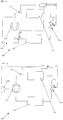
- FIG. 2 schematically illustrates a lamination valve 14 of the mechanical type currently widely used in known cooling plants.
- This valve 14 situated between the condenser 13 and the evaporator 12, receives the high-pressure gas from an inlet tube 16 where it enters into a first sealed chamber 17 separated from the rest of the valve body 23 through a septum 18 having a hole 19.
- the mechanical organs 20, 21 which regulate the passage of the fluid from the first sealed chamber 17 to the remaining part 23 of the valve body.
- Said mechanical organs 20, 21 generally comprise a shutter 21 integrally fixed to a spring 20.
- the shutter 21 has the function of opening or closing the hole 19 present on the septum 18.
- the nebulized fluid then leaves the outlet tube 27 situated in the remaining part 23 of the valve body and is directed towards the evaporator 12 where it cools the food mixture and is in turn heated.
- the regulation of the entity of the cooling effect of the cooling plant 10 is generally effected by acting on the lamination valve 14.
- thermostat-regulated bulb 15 is currently envisaged, downstream of the evaporator 12, which reveals the temperature of the fluid at the outlet of the evaporator 12.
- the bulb 15 is connected through a connection tube 22 to a second sealed chamber 24 situated above a piston 25 which separates the lamination valve 14 from said second chamber 24.
- the piston 25 is integrally fixed to the mechanical means 20, 21 of the lamination valve 14 by suitable device, such as for example a rod 26.
- the bulb 15 and the connection tube 22 contain a fluid which expands when the temperature revealed by the bulb 15 is higher than room temperature, whereas it contracts if the temperature revealed is lower.
- the fluid At the outlet of the evaporator 12, the fluid is completely gaseous and the bulb 15 absorbs its temperature, which, at the beginning of the cooling process, is generally relatively high as the cooling liquid has absorbed a great deal of heat from the food mixture to be cooled.
- the high temperature of the cooling fluid heats the fluid present in the bulb 15 which expands in the second sealed chamber 24 acting on the piston 25 which in turn compresses the spring 20 of the lamination valve 14.
- the shutter 21 thus partially frees the hole 19 situated on the septum 18.
- This larger opening causes a greater presence of nebulized liquid in the evaporator 12 and therefore a greater removal of heat from the food mixture.
- This regulation is in fact relatively slow, as the bulb 15 is not capable of reacting in rapid times with a variation in temperature of the cooling fluid leaving the evaporator 12.
- the slow reaction of the bulb 15 with this rapid variation in temperature leads to an excessive decrease in the temperature of the fluid downstream of the evaporator 12 which generally undergoes a drastic collapse to an extent of as much as 50%.
- connection tube 22 between the bulb 15 and the chamber 24 is also another weak point of the mechanical lamination valve, this point is specifically the connection tube 22 between the bulb 15 and the chamber 24.
- This bulb is very thin (to reduce the thermal exchanges with the surrounding environment to the maximum) but is parellelly also extremely fragile, should said duct 22 in fact undergo breakage with a loss of the gas contained in it, the lamination valve 14 would no longer be able to react to the changes in temperature at the outlet of the evaporator 12, completely closing the laminating mouth 19 and causing a pressure drop inside the evaporator 12 which would reach excessively low levels in very rapid times forcing the compressor 11 to bring the whole plant 10 to vacuum conditions.
- a low-pressure safety manostat (not illustrated) would intervene which, by blocking the compressor 11, also blocks the whole processing. This creates considerable productive delays and requires the intervention of specialized staff to be able to restart the processing.
- a general objective of the present invention is to solve the drawbacks of the known art described above in an extremely simple, economical and particularly functional manner.
- a further objective of the present invention is to create a method for a cooling plant which is capable of rapidly reaching the desired entity of the cooling effect and does not have the phenomenon of swinging during the phase when this cooling effect is reached.
- Another objective of the present invention is to create a method for a cooling plant which does not encounter stoppage conditions caused by an excessively low pressure inside the plant.
- Yet another objective of the present invention is to provide a method for a cooling plant which is capable of maintaining minimum consumption regimes without encountering excessively low pressure conditions inside the plant.
- a further objective of the present invention is to create a regulation method of a cooling plant which allows it to reach a cooling effect of a desired entity avoiding swinging phenomena.
- the cooling plant 100 comprises a closed circuit in which a cooling fluid flows and which connects an evaporator 112, a compressor 111, a condenser 113 and a lamination valve 114 in succession.
- the lamination valve 114 used in the cooling plant 100 is of the electromechanical type and is electronically driven by a processing unit 120 such as for example an electronic centre.
- the lamination valve 114 of the electromechanical type comprises a servomechanism consisting of an electric motor 116 of the stepper type which, by means of a worm screw 117 entrusted to the same, drives the translation of a plug 118 thus modifying the engagement degree of the same with a gas outlet mouth 119.
- the electromechanical lamination valve 114 can be of the solenoid type which raises and lowers a drum which in turn closes or opens the mouth.
- an electromechanical lamination valve 114 consisting of two superimposed plates, of which one is perforated for a part of the circumference whereas the other is in the shape of a half-moon and is moveable under the action of an electric motor so as to uncover a variable number of holes depending on the lamination degree necessary.
- valves all have the same capacity of opening and closing the mouth in rapid times and also allow, if suitably driven, extremely rapid reaction times to be obtained with negligible variations with a good precision level.
- the opening and/or closing of the lamination valve 114 is piloted by a timed processing unit 120, or on the basis of the values revealed by at least one probe 115 suitable for measuring a significant parameter of the flow-rate of cold cooling fluid necessary for obtaining the particular cooling action desired.
- This parameter for example can be the temperature.
- one or more probes 115 are used, which reveal the temperature of the cooling fluid.
- Said probes 115 are preferably positioned downstream the evaporator 112 in order to determine the temperature of the cooling fluid immediately after the heat exchange which takes place in the evaporator 112 with the food mixture to be cooled. It is thus possible to obtain a measurement which indicates the state of the mixture itself and determine whether the cooling effect of the plant 100 is sufficient.
- a temperature which is indicated as being greater than the desired value implies an insufficient opening of the lamination valve 114 and therefore an insufficient flow-rate of the cold cooling fluid towards the food mixture.
- probes 115 for determining the pressure of the cooling fluid also preferably situated downstream of the evaporator 112.
- These probes 115 are also capable of indirectly providing an index measurement of the instantaneous state of the food mixture and thus determining if the cooling effect of the plant 100 is sufficient.
- a pressure which is indicated as being greater than the desired value implies an insufficient opening of the lamination valve 114 and therefore an insufficient flow-rate of the cold cooling fluid towards the food mixture.
- temperature probes in contact with the mixture to be cooled are used, or ionic or tension probes, for example such as those described in Italian patent IT 1 301 892 owned by the Applicant, capable of determining the creaming degree of the food mixture.
- Said probes 115 are preferably immersed in the food mixture to be cooled.
- the cooling plant 100 additionally comprises a second valve 123, preferably of the electromechanical solenoid type, situated downstream of the compressor 111 and which controls the opening of a bypass tube 124 capable of short-circuiting the supply of the compressor 111 to the low-pressure area.
- a second valve 123 preferably of the electromechanical solenoid type
- the second valve 123 is controlled by the processing unit 120 which receives an activation signal at the inlet from a safety manometer (not illustrated) when the same reveals an excessively low pressure value upstream of the compressor 111.
- the processing unit 120 pilots the second valve 123 which is opening, allowing the excess gas to flow through the bypass tube 124.
- Said bypass tube 124 is suitably dimensioned so that not all the gas flows through it. The suction pressure is therefore kept high avoiding the intervention of the safety manometer.
- the use of a bypass tube 124 piloted in the opening by a second valve 123 prevents the compressor 111 from bringing the whole plant 110 to vacuum conditions by the intervention of the low-pressure safety manometer, which would block the compressor and therefore the whole processing.
- the third embodiment illustrated in figure 9 differs in the fact that the compressor 111' is of the type comprising an electric motor (not illustrated) which regulates the functioning rate of the compression chamber, modulating the cooling capacity of the same 111'.
- the electric motor of the compressor 111' is driven by an inverter 125 in turn piloted by means of the processing unit 120.
- the processing unit 120 is based on the signal which it receives at the inlet from the probe 115.
- the functioning of the cooling plant 100 is the following.
- the processing unit 120 commands the opening of the lamination valve 114 i.e., in the specific case of the embodiment illustrated, it drives the electric motor 116 so as to lift the plug 118 by a predetermined number of pitches, thus nebulizing a greater quantity of cooling liquid.
- the processing unit 120 commands the closing of the lamination valve 114 reducing the presence of cooling fluid in the evaporator 112.
- the processing unit 120 receives at the inlet the values revealed by the probes 115 and suitably processes them through the software means 122 in order to determine the required opening degree of the lamination valve 114 and consequently the commands to be given to the servomechanism present in the same 114.
- the software means implement a method 200 ( figure 10 ) for determining the optimum opening of the lamination valve 114 comprising the following phases.
- phase 210 First of all the instantaneous values of the parameters measured T s by the at least one probe 115 are acquired (phase 210). For each reading more sampling values are acquired and processes, for example through mean values and the elimination of spurious values, in order to obtain a significant datum of the parameter revealed.
- the initial opening X of the valve 114 is subsequently established (phase 220).
- the values of the parameters T s revealed and, depending on the case, suitably processed, are compared (phase 230) with a limit value T l known from the projecting and below which a loss in efficiency of the cooling plant 100 is obtained.
- the opening of a first incremental value Y is modified, depending on the particular value of the parameter measured T s according to a logarithmic law whose argument is given by the sum of the parameter measured T s and a limit value T 0 of said parameter, corresponding to a limit value X 0 of the opening of the valve known from the project characteristics of the lamination organ 118 below which the lamination is ineffective.
- the corresponding incremental value Y for the opening of the valve 114 is read (phase 235) in the memory means and subtracted (phase 240) from the opening value X previously known, obtaining the corresponding trace value of the function described above.
- this operation is interrupted if the verification phase 250 reveals that the opening limit value X 0 has been reached corresponding to the annulment limit value T 0 of the argument of the logarithm.
- phase 260 the limit value T l relating to the reference parameter revealed by the probes 115 is updated (phase 260) on the basis of the variation in the lamination of the cooling fluid and therefore depending on the opening degree X of the valve 114.
- a second incremental value T t is added to the limit value T l , which can have a positive or negative value, depending on the opening degree X of the valve according to a trigonometric law inverse to the tangent having an argument proportional to the opening degree X.
- the processing unit 120 therefore pilots the electric motor 116 of the lamination valve 114 to allow the laminating passage 119 to be freed or blocked in negligible reaction times.
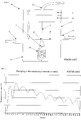
- This control effected on a parameter of the food mixture (temperature and/or creaming degree) or cooling means (temperature and/or pressure) also effectively prevents swinging as shown in figure 5 .
- the processing unit 120 pilots the opening of lamination valve 114, the feeding frequency of the compressor 111' imposed by the inverter 125 is contemporaneously increased, adapting it to the opening degree of the lamination valve 114.
- the processing unit 120 commands the closing of the lamination valve 114 reducing the presence of cooling fluid in the evaporator 112.
- the processing unit 120 imposes a decrease in the frequency generated by the inverter 125 thus reducing the rate of the compressor 111', and therefore of the recirculation of the cooling fluid, still maintaining however the suction pressure supplied to the compressor 111' at values higher than the limit value above which the low-pressure safety manometer intervenes.
- Figure 6 compares the abatement curves of the temperature in a plant of the state of the art (curve L1) and a plant according to the present disclosure (curve L2) used for the production of a same quantity of the same type of ice-cream.
- the opening of the nozzle is regulated in closure so as to have a correct quantity of cooling fluid inside the evaporator, in this way using the whole evaporating capacity of the cooling fluid.
- This quantity must be finely regulated, above all during the change in state of the mixture in which there are no sudden temperature changes.
- the energy balance of the cooling machine is improved by about 20% as only the quantity of cooling fluid strictly necessary, is used.
- the energy balance of the cycle is worse, specifically as a result of the swinging which prevents there from being a desired quantity of cooling liquid in the evaporator. If, in fact, on an average, the quantity of fluid which circulates within the time unit is the same, this is not the case for the energy which, if there is an excessive quantity of fluid, is not fully exploited and, in the case of an insufficient quantity of fluid, is not available so that not all the heat which could be ideally removed in that instant is absorbed by the cooling fluid.
Landscapes
- Engineering & Computer Science (AREA)
- Physics & Mathematics (AREA)
- Mechanical Engineering (AREA)
- Thermal Sciences (AREA)
- General Engineering & Computer Science (AREA)
- Confectionery (AREA)
- Processes Of Treating Macromolecular Substances (AREA)
- Devices That Are Associated With Refrigeration Equipment (AREA)
Claims (7)
- Verfahren zum Regulieren einer Kühlanlage (100) mit einer hohen Kühlkapazität, insbesondere für ein Nahrungsmittelgemisch, wobei die Kühlanlage einen geschlossenen Kreislauf, in welchem ein Kühlfluid strömt, der einen Verdampfer (112), einen Verdichter (111), einen Kondensator (113) sowie ein Laminierungsventil (114) in Folge verbindet, wobei das Laminierungsventil (114) vom elektromechanischen Typ ist, eine Verarbeitungseinheit (120) umfasst, die mit zumindest einer Sonde (115) verbunden ist, die zum Messen eines Parameters abhängig von dem Durchfluss des Kühlfluides geeignet ist, das in dem Verdampfer (112) zirkuliert, wobei die Verarbeitungseinheit (120) mit dem Laminierungsventil (114) zum Steuern des Öffnens und/oder Schließens des Laminierungsventils (114) auf der Basis zumindest einer Messung verbunden ist, die durch die zumindest eine Sonde (115) erhalten wird, wobei das Verfahren Phasen enthält, die umfassen, dass:- zumindest ein Wert (TS) erlangt (210) wird, der von der zumindest einen Sonde (115) erlangt wird;- das Öffnen des Laminierungsventils (114) bis zu einem vorher eingerichteten Öffnungsgrad (X) gesteuert (220) wird;- das Öffnen des Laminierungsventils (114) mit einem ersten Differenzwert (Y) abhängig von dem Wert, der von der zumindest einen Sonde (115) erhalten (TS) wird, gemäß einem logarithmischen Variabilitätsgesetz modifiziert (235) wird,dadurch gekennzeichnet, dass
das Argument des logarithmischen Variabilitätsgesetzes durch die Summe des gemessenen Wertes (TS) und eines Grenzwertes (T0) gegeben ist, der einem Grenzwert des Öffnens des Ventils entspricht, das aus Projektcharakteristiken des Laminierungsorganes bekannt ist, unterhalb dem die Laminierung ineffektiv ist. - Verfahren für die Regulierung einer Kühlanlage (100) nach Anspruch 1, dadurch gekennzeichnet, dass sie auch eine Phase umfasst, die daraus besteht, dass der zumindest eine Wert (TS), der von der zumindest einen Sonde (115) erhalten wird, mit einem Grenzwert (T1) verglichen (230) wird und nur dann mit der Modifikationsphase (235) fortgefahren wird, wenn der zumindest eine Wert (TS), der beobachtet wurde, geringer als der Grenzwert (T1) ist.
- Verfahren für die Regulierung einer Kühlanlage (100) nach Anspruch 2, dadurch gekennzeichnet, dass es auch eine Phase umfasst, die daraus besteht, den Grenzwert (T1) abhängig von dem Öffnungsgrad (X) des Ventils (114) gemäß einem trigonometrischen Variabilitätsgesetz invers zu der Tangente zu aktualisieren (260).
- Verfahren für die Regulierung einer Kühlanlage (100) nach einem der Ansprüche 1 bis 3, dadurch gekennzeichnet, dass sie auch eine Phase umfasst, die daraus besteht, den Öffnungsgrad (X) des Laminierungsventils (114) mit einem Grenzschließwert (X0) zu vergleichen (250) und die Schließphase des Ventils (114) zu beenden, wenn der Öffnungsgrad (X) gleich dem Grenzwert (X0) ist.
- Verfahren für die Regulierung einer Kühlanlage (100) nach einem der Ansprüche 1 bis 4, dadurch gekennzeichnet, dass die Aufnahmephase (210) aus einem Erlangen einer Reihe von Abtastwerten (TS) und einem Verarbeiten der Reihe von Werten (TS) durch Mittelwert- und Eliminierungsarbeitsgänge falscher Werte besteht.
- Verfahren für die Regulierung einer Kühlanlage (100) nach einem der Ansprüche 1 bis 5, dadurch gekennzeichnet, dass die Modifizierungsphase (235) des Öffnens des Laminierungsventils (114) aus einem Steuern eines Elektromotors (116) besteht, um so das Laminierungsorgan (118) anzuheben oder abzusenken, um den einen Laminierungsdurchgang (119) freizumachen oder zu behindern.
- Verfahren für die Regulierung einer Kühlanlage (100) nach einem der Ansprüche 1 bis 6, dadurch gekennzeichnet, dass sie auch eine Phase umfasst, die daraus besteht, dass die Frequenz, die durch einen Umrichter (125) erzeugt wird, abhängig von dem Öffnungsgrad (X) des Laminierungsventils (114) modifiziert wird.
Priority Applications (1)
| Application Number | Priority Date | Filing Date | Title |
|---|---|---|---|
| SI200931903T SI2136162T1 (sl) | 2008-06-19 | 2009-05-19 | Metoda za regulacijo hladilne naprave z visoko hladilno zmogljivostjo, še posebej za procesiranje prehranskih mešanic |
Applications Claiming Priority (1)
| Application Number | Priority Date | Filing Date | Title |
|---|---|---|---|
| IT001118A ITMI20081118A1 (it) | 2008-06-19 | 2008-06-19 | Impianto frigorifero ad elevata capacita frigorigena, in particolare per la lavorazione di miscele alimentari, e metodo di regolazione dello stesso |
Publications (3)
| Publication Number | Publication Date |
|---|---|
| EP2136162A2 EP2136162A2 (de) | 2009-12-23 |
| EP2136162A3 EP2136162A3 (de) | 2015-04-29 |
| EP2136162B1 true EP2136162B1 (de) | 2018-10-17 |
Family
ID=40301827
Family Applications (1)
| Application Number | Title | Priority Date | Filing Date |
|---|---|---|---|
| EP09160603.8A Not-in-force EP2136162B1 (de) | 2008-06-19 | 2009-05-19 | Steuerungsverfahren fur Kühlanlage mit hoher Kühlkapazität, insbesondere zur Verarbeitung von Lebensmittelmischungen |
Country Status (3)
| Country | Link |
|---|---|
| EP (1) | EP2136162B1 (de) |
| IT (1) | ITMI20081118A1 (de) |
| SI (1) | SI2136162T1 (de) |
Families Citing this family (1)
| Publication number | Priority date | Publication date | Assignee | Title |
|---|---|---|---|---|
| WO2021239760A1 (fr) * | 2020-05-27 | 2021-12-02 | Valeo Systemes Thermiques | Dispositif de detente et un procede de controle du dispositif de detente |
Family Cites Families (7)
| Publication number | Priority date | Publication date | Assignee | Title |
|---|---|---|---|---|
| AU636726B2 (en) * | 1990-03-19 | 1993-05-06 | Mitsubishi Denki Kabushiki Kaisha | Air conditioning system |
| JPH0462358A (ja) * | 1990-06-29 | 1992-02-27 | Toshiba Corp | 空気調和装置 |
| JP2853976B2 (ja) * | 1995-06-01 | 1999-02-03 | オリオン機械株式会社 | 冷凍サイクルにおける運転開始時制御装置 |
| JPH0949662A (ja) * | 1995-08-09 | 1997-02-18 | Aisin Seiki Co Ltd | 圧縮式空調機 |
| IT1301892B1 (it) * | 1998-07-31 | 2000-07-07 | Bravo Spa | Sistema elettronico di controllo della mantecazione di una miscela inlavorazione in una macchina per la produzione di gelato. |
| US6711906B2 (en) * | 2001-04-20 | 2004-03-30 | Hankison International | Variable evaporator control for a gas dryer |
| JP2007127518A (ja) * | 2005-11-04 | 2007-05-24 | Alps Electric Co Ltd | 角度検出装置 |
-
2008
- 2008-06-19 IT IT001118A patent/ITMI20081118A1/it unknown
-
2009
- 2009-05-19 EP EP09160603.8A patent/EP2136162B1/de not_active Not-in-force
- 2009-05-19 SI SI200931903T patent/SI2136162T1/sl unknown
Non-Patent Citations (1)
| Title |
|---|
| None * |
Also Published As
| Publication number | Publication date |
|---|---|
| SI2136162T1 (sl) | 2019-02-28 |
| ITMI20081118A1 (it) | 2009-12-20 |
| EP2136162A2 (de) | 2009-12-23 |
| EP2136162A3 (de) | 2015-04-29 |
Similar Documents
| Publication | Publication Date | Title |
|---|---|---|
| CA2798399C (en) | Method to control electronic expansion valve | |
| CA2147065C (en) | Method of refrigeration case control | |
| EP1874127B1 (de) | Kühlsystem und verfahren für getränkespender | |
| US7784296B2 (en) | System and method for controlling an air conditioner or heat pump | |
| US7353659B2 (en) | System and method for controlling an economizer circuit | |
| JP2011122756A (ja) | 空気調和機、膨張弁の開度制御方法およびプログラム | |
| WO2005052468A1 (ja) | 冷蔵庫 | |
| JP2001518601A (ja) | パルス幅調整負荷サイクル・スクロール圧縮機を用いる冷却システム用の適応制御装置 | |
| CN101978227A (zh) | 制冷装置 | |
| CN103913024B (zh) | 用于控制变速压缩机的速度的方法 | |
| JP2004028555A (ja) | アイスクリーム製造機における冷媒の流量制御方法および流量制御装置 | |
| JPH06185815A (ja) | ヒートポンプ系統の制御方法と制御装置 | |
| CN103608630A (zh) | 制冷装置 | |
| WO2004088220A1 (en) | Refrigeration system and method for beverage dispenser | |
| CN104583691A (zh) | 用于控制冷却器系统的方法 | |
| EP2136162B1 (de) | Steuerungsverfahren fur Kühlanlage mit hoher Kühlkapazität, insbesondere zur Verarbeitung von Lebensmittelmischungen | |
| Tassou et al. | Investigation of the effects of thermostatic and electronic expansion valves on the steady-state and transient performance of commercial chillers | |
| JP5052173B2 (ja) | 自動製氷機の運転方法 | |
| JPH07229655A (ja) | 蒸気圧縮式冷凍機の冷媒流量制御装置 | |
| US20220053710A1 (en) | Refrigeration system with hot gas by-pass | |
| JP5504211B2 (ja) | 環境制御装置、並びに環境制御方法 | |
| WO2013007627A1 (en) | Humidity control in a refrigerated transport container with an intermittently operated compressor | |
| KR20200082221A (ko) | 냉장고 및 그의 제어방법 | |
| Tassou et al. | Investigation of the steady state and transient performance of a reciprocating chiller equipped with an electronic expansion valve | |
| US6629421B1 (en) | Method of and an apparatus for a self-governing pulse feeding refrigerant |
Legal Events
| Date | Code | Title | Description |
|---|---|---|---|
| PUAI | Public reference made under article 153(3) epc to a published international application that has entered the european phase |
Free format text: ORIGINAL CODE: 0009012 |
|
| AK | Designated contracting states |
Kind code of ref document: A2 Designated state(s): AT BE BG CH CY CZ DE DK EE ES FI FR GB GR HR HU IE IS IT LI LT LU LV MC MK MT NL NO PL PT RO SE SI SK TR |
|
| RIC1 | Information provided on ipc code assigned before grant |
Ipc: F25B 41/06 20060101AFI20141121BHEP |
|
| PUAL | Search report despatched |
Free format text: ORIGINAL CODE: 0009013 |
|
| AK | Designated contracting states |
Kind code of ref document: A3 Designated state(s): AT BE BG CH CY CZ DE DK EE ES FI FR GB GR HR HU IE IS IT LI LT LU LV MC MK MT NL NO PL PT RO SE SI SK TR |
|
| AX | Request for extension of the european patent |
Extension state: AL BA RS |
|
| RIC1 | Information provided on ipc code assigned before grant |
Ipc: F25B 41/06 20060101AFI20150320BHEP |
|
| 17P | Request for examination filed |
Effective date: 20151026 |
|
| RBV | Designated contracting states (corrected) |
Designated state(s): AT BE BG CH CY CZ DE DK EE ES FI FR GB GR HR HU IE IS IT LI LT LU LV MC MK MT NL NO PL PT RO SE SI SK TR |
|
| 17Q | First examination report despatched |
Effective date: 20160307 |
|
| STAA | Information on the status of an ep patent application or granted ep patent |
Free format text: STATUS: EXAMINATION IS IN PROGRESS |
|
| RAP1 | Party data changed (applicant data changed or rights of an application transferred) |
Owner name: BRAVO S.P.A. |
|
| GRAP | Despatch of communication of intention to grant a patent |
Free format text: ORIGINAL CODE: EPIDOSNIGR1 |
|
| STAA | Information on the status of an ep patent application or granted ep patent |
Free format text: STATUS: GRANT OF PATENT IS INTENDED |
|
| INTG | Intention to grant announced |
Effective date: 20180524 |
|
| GRAS | Grant fee paid |
Free format text: ORIGINAL CODE: EPIDOSNIGR3 |
|
| GRAA | (expected) grant |
Free format text: ORIGINAL CODE: 0009210 |
|
| STAA | Information on the status of an ep patent application or granted ep patent |
Free format text: STATUS: THE PATENT HAS BEEN GRANTED |
|
| AK | Designated contracting states |
Kind code of ref document: B1 Designated state(s): AT BE BG CH CY CZ DE DK EE ES FI FR GB GR HR HU IE IS IT LI LT LU LV MC MK MT NL NO PL PT RO SE SI SK TR |
|
| REG | Reference to a national code |
Ref country code: GB Ref legal event code: FG4D |
|
| REG | Reference to a national code |
Ref country code: CH Ref legal event code: EP |
|
| REG | Reference to a national code |
Ref country code: IE Ref legal event code: FG4D |
|
| REG | Reference to a national code |
Ref country code: DE Ref legal event code: R096 Ref document number: 602009055074 Country of ref document: DE Ref country code: AT Ref legal event code: REF Ref document number: 1054536 Country of ref document: AT Kind code of ref document: T Effective date: 20181115 |
|
| REG | Reference to a national code |
Ref country code: NL Ref legal event code: MP Effective date: 20181017 |
|
| REG | Reference to a national code |
Ref country code: LT Ref legal event code: MG4D |
|
| REG | Reference to a national code |
Ref country code: AT Ref legal event code: MK05 Ref document number: 1054536 Country of ref document: AT Kind code of ref document: T Effective date: 20181017 |
|
| PG25 | Lapsed in a contracting state [announced via postgrant information from national office to epo] |
Ref country code: NL Free format text: LAPSE BECAUSE OF FAILURE TO SUBMIT A TRANSLATION OF THE DESCRIPTION OR TO PAY THE FEE WITHIN THE PRESCRIBED TIME-LIMIT Effective date: 20181017 |
|
| PG25 | Lapsed in a contracting state [announced via postgrant information from national office to epo] |
Ref country code: HR Free format text: LAPSE BECAUSE OF FAILURE TO SUBMIT A TRANSLATION OF THE DESCRIPTION OR TO PAY THE FEE WITHIN THE PRESCRIBED TIME-LIMIT Effective date: 20181017 Ref country code: AT Free format text: LAPSE BECAUSE OF FAILURE TO SUBMIT A TRANSLATION OF THE DESCRIPTION OR TO PAY THE FEE WITHIN THE PRESCRIBED TIME-LIMIT Effective date: 20181017 Ref country code: LT Free format text: LAPSE BECAUSE OF FAILURE TO SUBMIT A TRANSLATION OF THE DESCRIPTION OR TO PAY THE FEE WITHIN THE PRESCRIBED TIME-LIMIT Effective date: 20181017 Ref country code: LV Free format text: LAPSE BECAUSE OF FAILURE TO SUBMIT A TRANSLATION OF THE DESCRIPTION OR TO PAY THE FEE WITHIN THE PRESCRIBED TIME-LIMIT Effective date: 20181017 Ref country code: NO Free format text: LAPSE BECAUSE OF FAILURE TO SUBMIT A TRANSLATION OF THE DESCRIPTION OR TO PAY THE FEE WITHIN THE PRESCRIBED TIME-LIMIT Effective date: 20190117 Ref country code: ES Free format text: LAPSE BECAUSE OF FAILURE TO SUBMIT A TRANSLATION OF THE DESCRIPTION OR TO PAY THE FEE WITHIN THE PRESCRIBED TIME-LIMIT Effective date: 20181017 Ref country code: PL Free format text: LAPSE BECAUSE OF FAILURE TO SUBMIT A TRANSLATION OF THE DESCRIPTION OR TO PAY THE FEE WITHIN THE PRESCRIBED TIME-LIMIT Effective date: 20181017 Ref country code: BG Free format text: LAPSE BECAUSE OF FAILURE TO SUBMIT A TRANSLATION OF THE DESCRIPTION OR TO PAY THE FEE WITHIN THE PRESCRIBED TIME-LIMIT Effective date: 20190117 Ref country code: IS Free format text: LAPSE BECAUSE OF FAILURE TO SUBMIT A TRANSLATION OF THE DESCRIPTION OR TO PAY THE FEE WITHIN THE PRESCRIBED TIME-LIMIT Effective date: 20190217 Ref country code: FI Free format text: LAPSE BECAUSE OF FAILURE TO SUBMIT A TRANSLATION OF THE DESCRIPTION OR TO PAY THE FEE WITHIN THE PRESCRIBED TIME-LIMIT Effective date: 20181017 |
|
| PG25 | Lapsed in a contracting state [announced via postgrant information from national office to epo] |
Ref country code: GR Free format text: LAPSE BECAUSE OF FAILURE TO SUBMIT A TRANSLATION OF THE DESCRIPTION OR TO PAY THE FEE WITHIN THE PRESCRIBED TIME-LIMIT Effective date: 20190118 Ref country code: PT Free format text: LAPSE BECAUSE OF FAILURE TO SUBMIT A TRANSLATION OF THE DESCRIPTION OR TO PAY THE FEE WITHIN THE PRESCRIBED TIME-LIMIT Effective date: 20190217 Ref country code: SE Free format text: LAPSE BECAUSE OF FAILURE TO SUBMIT A TRANSLATION OF THE DESCRIPTION OR TO PAY THE FEE WITHIN THE PRESCRIBED TIME-LIMIT Effective date: 20181017 |
|
| REG | Reference to a national code |
Ref country code: DE Ref legal event code: R097 Ref document number: 602009055074 Country of ref document: DE |
|
| PG25 | Lapsed in a contracting state [announced via postgrant information from national office to epo] |
Ref country code: DK Free format text: LAPSE BECAUSE OF FAILURE TO SUBMIT A TRANSLATION OF THE DESCRIPTION OR TO PAY THE FEE WITHIN THE PRESCRIBED TIME-LIMIT Effective date: 20181017 Ref country code: CZ Free format text: LAPSE BECAUSE OF FAILURE TO SUBMIT A TRANSLATION OF THE DESCRIPTION OR TO PAY THE FEE WITHIN THE PRESCRIBED TIME-LIMIT Effective date: 20181017 |
|
| PLBE | No opposition filed within time limit |
Free format text: ORIGINAL CODE: 0009261 |
|
| STAA | Information on the status of an ep patent application or granted ep patent |
Free format text: STATUS: NO OPPOSITION FILED WITHIN TIME LIMIT |
|
| PG25 | Lapsed in a contracting state [announced via postgrant information from national office to epo] |
Ref country code: SK Free format text: LAPSE BECAUSE OF FAILURE TO SUBMIT A TRANSLATION OF THE DESCRIPTION OR TO PAY THE FEE WITHIN THE PRESCRIBED TIME-LIMIT Effective date: 20181017 Ref country code: EE Free format text: LAPSE BECAUSE OF FAILURE TO SUBMIT A TRANSLATION OF THE DESCRIPTION OR TO PAY THE FEE WITHIN THE PRESCRIBED TIME-LIMIT Effective date: 20181017 Ref country code: RO Free format text: LAPSE BECAUSE OF FAILURE TO SUBMIT A TRANSLATION OF THE DESCRIPTION OR TO PAY THE FEE WITHIN THE PRESCRIBED TIME-LIMIT Effective date: 20181017 |
|
| 26N | No opposition filed |
Effective date: 20190718 |
|
| REG | Reference to a national code |
Ref country code: DE Ref legal event code: R119 Ref document number: 602009055074 Country of ref document: DE |
|
| REG | Reference to a national code |
Ref country code: CH Ref legal event code: PL |
|
| GBPC | Gb: european patent ceased through non-payment of renewal fee |
Effective date: 20190519 |
|
| PG25 | Lapsed in a contracting state [announced via postgrant information from national office to epo] |
Ref country code: MC Free format text: LAPSE BECAUSE OF FAILURE TO SUBMIT A TRANSLATION OF THE DESCRIPTION OR TO PAY THE FEE WITHIN THE PRESCRIBED TIME-LIMIT Effective date: 20181017 Ref country code: CH Free format text: LAPSE BECAUSE OF NON-PAYMENT OF DUE FEES Effective date: 20190531 Ref country code: LI Free format text: LAPSE BECAUSE OF NON-PAYMENT OF DUE FEES Effective date: 20190531 |
|
| REG | Reference to a national code |
Ref country code: BE Ref legal event code: MM Effective date: 20190531 |
|
| PG25 | Lapsed in a contracting state [announced via postgrant information from national office to epo] |
Ref country code: LU Free format text: LAPSE BECAUSE OF NON-PAYMENT OF DUE FEES Effective date: 20190519 |
|
| PG25 | Lapsed in a contracting state [announced via postgrant information from national office to epo] |
Ref country code: DE Free format text: LAPSE BECAUSE OF NON-PAYMENT OF DUE FEES Effective date: 20191203 Ref country code: GB Free format text: LAPSE BECAUSE OF NON-PAYMENT OF DUE FEES Effective date: 20190519 Ref country code: IE Free format text: LAPSE BECAUSE OF NON-PAYMENT OF DUE FEES Effective date: 20190519 |
|
| PG25 | Lapsed in a contracting state [announced via postgrant information from national office to epo] |
Ref country code: BE Free format text: LAPSE BECAUSE OF NON-PAYMENT OF DUE FEES Effective date: 20190531 |
|
| PG25 | Lapsed in a contracting state [announced via postgrant information from national office to epo] |
Ref country code: FR Free format text: LAPSE BECAUSE OF NON-PAYMENT OF DUE FEES Effective date: 20190531 |
|
| PGFP | Annual fee paid to national office [announced via postgrant information from national office to epo] |
Ref country code: IT Payment date: 20200522 Year of fee payment: 12 |
|
| PG25 | Lapsed in a contracting state [announced via postgrant information from national office to epo] |
Ref country code: CY Free format text: LAPSE BECAUSE OF FAILURE TO SUBMIT A TRANSLATION OF THE DESCRIPTION OR TO PAY THE FEE WITHIN THE PRESCRIBED TIME-LIMIT Effective date: 20181017 |
|
| PG25 | Lapsed in a contracting state [announced via postgrant information from national office to epo] |
Ref country code: HU Free format text: LAPSE BECAUSE OF FAILURE TO SUBMIT A TRANSLATION OF THE DESCRIPTION OR TO PAY THE FEE WITHIN THE PRESCRIBED TIME-LIMIT; INVALID AB INITIO Effective date: 20090519 Ref country code: MT Free format text: LAPSE BECAUSE OF FAILURE TO SUBMIT A TRANSLATION OF THE DESCRIPTION OR TO PAY THE FEE WITHIN THE PRESCRIBED TIME-LIMIT Effective date: 20181017 |
|
| PG25 | Lapsed in a contracting state [announced via postgrant information from national office to epo] |
Ref country code: MK Free format text: LAPSE BECAUSE OF FAILURE TO SUBMIT A TRANSLATION OF THE DESCRIPTION OR TO PAY THE FEE WITHIN THE PRESCRIBED TIME-LIMIT Effective date: 20181017 |
|
| PG25 | Lapsed in a contracting state [announced via postgrant information from national office to epo] |
Ref country code: IT Free format text: LAPSE BECAUSE OF NON-PAYMENT OF DUE FEES Effective date: 20200519 |
|
| P01 | Opt-out of the competence of the unified patent court (upc) registered |
Effective date: 20230610 |
|
| PGFP | Annual fee paid to national office [announced via postgrant information from national office to epo] |
Ref country code: SI Payment date: 20230504 Year of fee payment: 15 |
|
| PG25 | Lapsed in a contracting state [announced via postgrant information from national office to epo] |
Ref country code: TR Free format text: LAPSE BECAUSE OF NON-PAYMENT OF DUE FEES Effective date: 20190519 |
|
| REG | Reference to a national code |
Ref country code: SI Ref legal event code: KO00 Effective date: 20240520 |
|
| PG25 | Lapsed in a contracting state [announced via postgrant information from national office to epo] |
Ref country code: IT Free format text: LAPSE BECAUSE OF NON-PAYMENT OF DUE FEES Effective date: 20210519 |