EP2136119B1 - Screwing element and pipe connection device for attaching pipes - Google Patents
Screwing element and pipe connection device for attaching pipes Download PDFInfo
- Publication number
- EP2136119B1 EP2136119B1 EP08010964A EP08010964A EP2136119B1 EP 2136119 B1 EP2136119 B1 EP 2136119B1 EP 08010964 A EP08010964 A EP 08010964A EP 08010964 A EP08010964 A EP 08010964A EP 2136119 B1 EP2136119 B1 EP 2136119B1
- Authority
- EP
- European Patent Office
- Prior art keywords
- screw
- coating
- pipe
- thread
- friction
- Prior art date
- Legal status (The legal status is an assumption and is not a legal conclusion. Google has not performed a legal analysis and makes no representation as to the accuracy of the status listed.)
- Active
Links
- 238000000576 coating method Methods 0.000 claims description 125
- 239000011248 coating agent Substances 0.000 claims description 122
- 238000005260 corrosion Methods 0.000 description 13
- 230000007797 corrosion Effects 0.000 description 10
- 239000000314 lubricant Substances 0.000 description 8
- 229920001343 polytetrafluoroethylene Polymers 0.000 description 8
- 239000004810 polytetrafluoroethylene Substances 0.000 description 8
- -1 polytetrafluoroethylene Polymers 0.000 description 6
- 238000000034 method Methods 0.000 description 5
- XAGFODPZIPBFFR-UHFFFAOYSA-N aluminium Chemical compound [Al] XAGFODPZIPBFFR-UHFFFAOYSA-N 0.000 description 4
- 229910052782 aluminium Inorganic materials 0.000 description 4
- CWQXQMHSOZUFJS-UHFFFAOYSA-N molybdenum disulfide Chemical compound S=[Mo]=S CWQXQMHSOZUFJS-UHFFFAOYSA-N 0.000 description 4
- 229910052982 molybdenum disulfide Inorganic materials 0.000 description 4
- 238000005507 spraying Methods 0.000 description 4
- 239000000853 adhesive Substances 0.000 description 3
- 230000001070 adhesive effect Effects 0.000 description 3
- 238000007598 dipping method Methods 0.000 description 3
- 238000009957 hemming Methods 0.000 description 3
- 239000011324 bead Substances 0.000 description 2
- 230000000295 complement effect Effects 0.000 description 2
- QELJHCBNGDEXLD-UHFFFAOYSA-N nickel zinc Chemical compound [Ni].[Zn] QELJHCBNGDEXLD-UHFFFAOYSA-N 0.000 description 2
- 239000004411 aluminium Substances 0.000 description 1
- 230000005540 biological transmission Effects 0.000 description 1
- 239000012530 fluid Substances 0.000 description 1
- 239000000446 fuel Substances 0.000 description 1
- 238000007789 sealing Methods 0.000 description 1
Images
Classifications
-
- F—MECHANICAL ENGINEERING; LIGHTING; HEATING; WEAPONS; BLASTING
- F16—ENGINEERING ELEMENTS AND UNITS; GENERAL MEASURES FOR PRODUCING AND MAINTAINING EFFECTIVE FUNCTIONING OF MACHINES OR INSTALLATIONS; THERMAL INSULATION IN GENERAL
- F16B—DEVICES FOR FASTENING OR SECURING CONSTRUCTIONAL ELEMENTS OR MACHINE PARTS TOGETHER, e.g. NAILS, BOLTS, CIRCLIPS, CLAMPS, CLIPS OR WEDGES; JOINTS OR JOINTING
- F16B37/00—Nuts or like thread-engaging members
-
- F—MECHANICAL ENGINEERING; LIGHTING; HEATING; WEAPONS; BLASTING
- F16—ENGINEERING ELEMENTS AND UNITS; GENERAL MEASURES FOR PRODUCING AND MAINTAINING EFFECTIVE FUNCTIONING OF MACHINES OR INSTALLATIONS; THERMAL INSULATION IN GENERAL
- F16L—PIPES; JOINTS OR FITTINGS FOR PIPES; SUPPORTS FOR PIPES, CABLES OR PROTECTIVE TUBING; MEANS FOR THERMAL INSULATION IN GENERAL
- F16L19/00—Joints in which sealing surfaces are pressed together by means of a member, e.g. a swivel nut, screwed on or into one of the joint parts
- F16L19/02—Pipe ends provided with collars or flanges, integral with the pipe or not, pressed together by a screwed member
- F16L19/025—Pipe ends provided with collars or flanges, integral with the pipe or not, pressed together by a screwed member the pipe ends having integral collars or flanges
- F16L19/028—Pipe ends provided with collars or flanges, integral with the pipe or not, pressed together by a screwed member the pipe ends having integral collars or flanges the collars or flanges being obtained by deformation of the pipe wall
- F16L19/0286—Pipe ends provided with collars or flanges, integral with the pipe or not, pressed together by a screwed member the pipe ends having integral collars or flanges the collars or flanges being obtained by deformation of the pipe wall and being formed as a flange
-
- B—PERFORMING OPERATIONS; TRANSPORTING
- B60—VEHICLES IN GENERAL
- B60T—VEHICLE BRAKE CONTROL SYSTEMS OR PARTS THEREOF; BRAKE CONTROL SYSTEMS OR PARTS THEREOF, IN GENERAL; ARRANGEMENT OF BRAKING ELEMENTS ON VEHICLES IN GENERAL; PORTABLE DEVICES FOR PREVENTING UNWANTED MOVEMENT OF VEHICLES; VEHICLE MODIFICATIONS TO FACILITATE COOLING OF BRAKES
- B60T17/00—Component parts, details, or accessories of power brake systems not covered by groups B60T8/00, B60T13/00 or B60T15/00, or presenting other characteristic features
- B60T17/04—Arrangements of piping, valves in the piping, e.g. cut-off valves, couplings or air hoses
- B60T17/043—Brake line couplings, air hoses and stopcocks
-
- F—MECHANICAL ENGINEERING; LIGHTING; HEATING; WEAPONS; BLASTING
- F02—COMBUSTION ENGINES; HOT-GAS OR COMBUSTION-PRODUCT ENGINE PLANTS
- F02B—INTERNAL-COMBUSTION PISTON ENGINES; COMBUSTION ENGINES IN GENERAL
- F02B77/00—Component parts, details or accessories, not otherwise provided for
-
- F—MECHANICAL ENGINEERING; LIGHTING; HEATING; WEAPONS; BLASTING
- F16—ENGINEERING ELEMENTS AND UNITS; GENERAL MEASURES FOR PRODUCING AND MAINTAINING EFFECTIVE FUNCTIONING OF MACHINES OR INSTALLATIONS; THERMAL INSULATION IN GENERAL
- F16B—DEVICES FOR FASTENING OR SECURING CONSTRUCTIONAL ELEMENTS OR MACHINE PARTS TOGETHER, e.g. NAILS, BOLTS, CIRCLIPS, CLAMPS, CLIPS OR WEDGES; JOINTS OR JOINTING
- F16B7/00—Connections of rods or tubes, e.g. of non-circular section, mutually, including resilient connections
-
- F—MECHANICAL ENGINEERING; LIGHTING; HEATING; WEAPONS; BLASTING
- F16—ENGINEERING ELEMENTS AND UNITS; GENERAL MEASURES FOR PRODUCING AND MAINTAINING EFFECTIVE FUNCTIONING OF MACHINES OR INSTALLATIONS; THERMAL INSULATION IN GENERAL
- F16L—PIPES; JOINTS OR FITTINGS FOR PIPES; SUPPORTS FOR PIPES, CABLES OR PROTECTIVE TUBING; MEANS FOR THERMAL INSULATION IN GENERAL
- F16L19/00—Joints in which sealing surfaces are pressed together by means of a member, e.g. a swivel nut, screwed on or into one of the joint parts
- F16L19/02—Pipe ends provided with collars or flanges, integral with the pipe or not, pressed together by a screwed member
- F16L19/0243—Pipe ends provided with collars or flanges, integral with the pipe or not, pressed together by a screwed member specially adapted for use with coated pipes
-
- F—MECHANICAL ENGINEERING; LIGHTING; HEATING; WEAPONS; BLASTING
- F16—ENGINEERING ELEMENTS AND UNITS; GENERAL MEASURES FOR PRODUCING AND MAINTAINING EFFECTIVE FUNCTIONING OF MACHINES OR INSTALLATIONS; THERMAL INSULATION IN GENERAL
- F16L—PIPES; JOINTS OR FITTINGS FOR PIPES; SUPPORTS FOR PIPES, CABLES OR PROTECTIVE TUBING; MEANS FOR THERMAL INSULATION IN GENERAL
- F16L33/00—Arrangements for connecting hoses to rigid members; Rigid hose connectors, i.e. single members engaging both hoses
- F16L33/02—Hose-clips
- F16L33/04—Hose-clips tightened by tangentially-arranged threaded pin and nut
- F16L33/06—Hose-clips tightened by tangentially-arranged threaded pin and nut in which the threaded pin is rigid with the hose-encircling member
-
- F—MECHANICAL ENGINEERING; LIGHTING; HEATING; WEAPONS; BLASTING
- F02—COMBUSTION ENGINES; HOT-GAS OR COMBUSTION-PRODUCT ENGINE PLANTS
- F02M—SUPPLYING COMBUSTION ENGINES IN GENERAL WITH COMBUSTIBLE MIXTURES OR CONSTITUENTS THEREOF
- F02M55/00—Fuel-injection apparatus characterised by their fuel conduits or their venting means; Arrangements of conduits between fuel tank and pump F02M37/00
- F02M55/004—Joints; Sealings
-
- Y—GENERAL TAGGING OF NEW TECHNOLOGICAL DEVELOPMENTS; GENERAL TAGGING OF CROSS-SECTIONAL TECHNOLOGIES SPANNING OVER SEVERAL SECTIONS OF THE IPC; TECHNICAL SUBJECTS COVERED BY FORMER USPC CROSS-REFERENCE ART COLLECTIONS [XRACs] AND DIGESTS
- Y10—TECHNICAL SUBJECTS COVERED BY FORMER USPC
- Y10T—TECHNICAL SUBJECTS COVERED BY FORMER US CLASSIFICATION
- Y10T29/00—Metal working
- Y10T29/49—Method of mechanical manufacture
- Y10T29/49826—Assembling or joining
- Y10T29/49947—Assembling or joining by applying separate fastener
- Y10T29/49963—Threaded fastener
Definitions
- the invention relates to a screw, in particular for the connection or for the connection of pipes, preferably of motor vehicle piping, wherein a thread is provided, as well as at least one thread-free contact surface.
- the invention further relates to a pipe connection device for the connection of pipes, in particular motor vehicle piping with such a screw.
- Screw elements or pipe connection devices of the type described above are known from practice in various embodiments.
- screw elements are known, with which a pipe, in particular a motor vehicle pipeline can be connected to a connection element.
- These known erfittings are usually provided with a coating, in particular with an anti-corrosion coating, which normally covers the entire fitting. The coating is applied, for example, by dipping or spraying.
- the coating is applied, for example, by dipping or spraying.
- the torsion of the pipe generates a return torque, which can lead to an unwanted or uncontrolled loosening or loosening of the screw connection.
- An undesirable loosening or loosening of the screw connection can in particular also be caused by vibrations, as occur, for example, in motor vehicles.
- EP-A-0 997 677 describes a screw element for the connection of pipelines.
- the invention is based on the technical problem of specifying a screw of the type described above, with an unwanted loosening or loosening of the associated screw can be avoided in a simple, effective and reliable manner.
- the invention is further based on the technical problem of specifying a corresponding pipe connection device.
- the invention teaches a screw, in particular for the connection or for the connection of pipe lines, preferably of motor vehicle piping, wherein a thread is provided and at least one thread-free contact surface is present, wherein the thread is at least partially provided with a first coating having a first coefficient of friction ⁇ 1 , wherein the contact surface is at least partially provided with a second coating having a second coefficient of friction ⁇ 2 and wherein the first coefficient of friction ⁇ 1 is greater, in particular significantly greater than the second coefficient of friction ⁇ 2 .
- the first coating on the thread forms the outer surface in the region of the thread or is the outermost coating of the thread.
- the second coating on the at least one contact surface forms the outer surface in the region of the contact surface or the outermost coating of the contact surface is.
- the thread is completely or substantially completely provided with the first coating.
- the contact surface is completely or substantially completely provided with the second coating.
- the first coating is not an adhesive coating.
- the screw is a bolt or a screw fitting having a thread formed as an external thread. Then this external thread of the screw bolt or screw fitting is at least partially and preferably completely or substantially completely provided with the first coating.
- the screw element is a screw fitting to which a pipeline is connected.
- the pipe passes through the screw fitting in the axial direction and engages behind the end of the screw fitting with a pipe end. The end of the pipe is recommended designed as a crimp.
- the at least one unthreaded contact surface or the unthreaded contact surfaces of the screw are oriented perpendicular or transversely or substantially perpendicular or substantially transversely to the screwing of the screw.
- the recommended embodiment has the Stimende of the bolt or screw fitting on a thread-free contact surface, which is at least partially coated with the second coating with the second coefficient of friction ⁇ 2 .
- this thread-free contact surface is completely provided or coated at the end of the screw or rantfittings with the second coating.
- the screw or screw fitting has a screw head and that the thread-side underside of the screw head has a thread-free contact surface which is at least partially coated with the second coating with the second coefficient of friction ⁇ 2 .
- this thread-free contact surface on the underside of the screw head is completely or substantially completely provided with the second coating.
- the screw is a nut having a thread formed as an internal thread. Then this internal thread is at least partially and preferably completely or substantially completely coated with the first coating.
- the nut serves to receive a bolt or fferfittings and recommended for receiving a coated according to the invention bolt or sterfittings.
- the nut may be an internally threaded connection sleeve for connecting two pipes or an internally threaded blind hole in a connection block for a pipe to be connected. It is within the scope of the invention that a contact flange of the connection sleeve has a thread-free contact surface, which is then at least partially and preferably completely or substantially completely provided with the second coating.
- both a screw bolt or screw fitting is coated according to the invention as well as a screw bolt associated nut according to the invention coated.
- the first coefficient of friction ⁇ 1 is at least twice, preferably at least three times and particularly preferably at least four times the second coefficient of friction ⁇ 2 .
- the first coefficient of friction ⁇ 1 is at least five times the second coefficient of friction ⁇ 2 .
- a variant of the screw element according to the invention is characterized in that the first coating with the first coefficient of friction ⁇ 1 is applied to both the thread and the at least one thread-free contact surface and that the second coating with the second coefficient of friction ⁇ 2 on the at least one thread-free contact surface - the first coating covering there - is applied.
- the entire screw element or at least the thread and the unthreaded contact surfaces of the screw is provided with the first coating and then the second coating is applied to the first coating in the area of the unthreaded contact surface or in the area of the unthreaded contact surfaces, so that the second coating the outer surface forms at the thread-free contact surfaces.
- the first coating is suitably applied in this embodiment by a dipping process.
- the second coating can be applied as part of a spraying process.
- Another embodiment of the invention is characterized in that the first coating with the first coefficient of friction ⁇ 1 is applied at least partially to the thread and that the second coating with the second coefficient of friction ⁇ 2 is applied only to the at least one thread-free contact surface.
- the first Coating applied only to the thread and not on the at least one thread-free contact surface and the second coating is applied to the at least one thread-free contact surface without interposition of the first coating.
- the first and the second coating for example, each be applied in the course of a spraying process.
- the first coating is an aluminum-containing corrosion protection coating which has or contains at least one lubricant which increases the coefficient of friction of the coating.
- the second coating has at least one lubricant which reduces the coefficient of friction of the coating, and this lubricant is expediently polytetrafluoroethylene (PTFE) and / or molybdenum disulfide (MoS 2 ).
- the coefficient of friction ⁇ 1 of the first coating is preferably 0.15 to 0.5, preferably 0.2 to 0.45 and preferably 0.25 to 0.4.
- a coefficient of friction ⁇ 1 between 0.3 and 0.4, for example 0.35, has proven itself.
- the coefficient of friction ⁇ 2 of the second coating is 0.02 to 0.2, preferably 0.02 to 0.15 and preferably 0.03 to 0.1. It has been proven that the coefficient of friction ⁇ 2 of the second coating is between 0.03 and 0.08 and, for example, is 0.05.
- the layer thickness of the first coating is expediently from 2 ⁇ m to 25 ⁇ m and preferably from 3 ⁇ m to 20 ⁇ m.
- the layer thickness of the second coating is 5 microns to 25 microns and preferably 5 microns to 20 microns.
- the invention also relates to a pipe connection device for the connection of pipelines, in particular of motor vehicle pipelines, wherein the pipe connection device has a screw element according to the invention and wherein a pipe is connected to this screw element.
- the screw with the connected pipe can be connected to a connection element by screwing.
- the aforementioned screw element is a screw bolt or a screw fitting with a connected pipe.
- the connection element can then be a connection sleeve with a connected second pipeline.
- the screw connection then serves to connect two pipes, in particular motor vehicle pipelines.
- the connecting element can also be a blind bore in a connection block, into which the screw bolt or the screw fitting with the connected pipeline can be screwed.
- a particularly preferred embodiment of the invention is characterized in that the screw is a screw with an axial bore, which axial bore is penetrated by the pipe, wherein the pipe has a flange at its pipe end and wherein the provided with the second coating Stimende the SSfittings on the Bördel Wegseite of the flange is applied. It is also within the scope of the invention that the crimp back of the pipe end is provided with the second coating. It is also within the scope of the invention that the thread of the screw fitting is provided with the first coating. Appropriately, the Stimende of the screw fitting is at least partially positively against the crimp back.
- the flare at the end of the pipe is an F-flare
- the flare back is oriented perpendicular or substantially perpendicular to the pipe longitudinal axis and the Stimende of synchronfittings then has at least one perpendicular or substantially perpendicular to the pipe longitudinal axis oriented surface portion of the form-fitting manner the crimp back rests.
- the surface section runs around the circumference of the screw fitting.
- the flare at the end of the pipe is an E-flare whose flare back is conical or substantially cone-shaped and the end of the ringfittings has at least one conical or substantially conical surface portion which rests positively on the flare back.
- this surface section runs around the circumference of the screw fitting.
- the flare at the end of the pipe can also have other shapes.
- the butt end of the screw fitting rests at least partially and recommended over the entire circumference of the screw fitting positively against the crimp back of the pipe end.
- the screw is a nut with an axial bore, which axial bore is penetrated by the pipeline, wherein the pipe has a flange at its pipe end, wherein the nut has a provided with the second coating, inside contact flange and wherein the Bördel the pipe rests with its bead back on the contact flange.
- the contact flange is at least partially and preferably over the entire circumference of the crimp on a form-fitting on the hemming back.
- the flare is an F flare whose flanged rear side is oriented perpendicularly or substantially perpendicular to the longitudinal axis of the pipe, and the contact flange of the screw nut has at least one surface section oriented perpendicularly or substantially perpendicular to the pipe longitudinal axis, which bears against the flare back side in a form-fitting manner.
- the flare is an E-flare
- the flare rear side is conical or substantially cone-shaped and the contact flange of the nut has at least one cone-shaped or substantially cone-shaped surface portion, which rests positively on the crimp back.
- the nut has an internal thread for receiving a connection element and this internal thread is provided with the first coating.
- the screw element is a screw fitting, and that the end of the screw fitting rests on the crimp back of the flare at the pipe end in the mounted state of the pipe connection device.
- F ax axial contact force
- F ax axial contact force
- M torque M
- the purpose of the second coating at the front end of the screw fitting is to minimize the transmitted torque M.
- a torque of 0.2 to 2, 5 Nm, preferably from 0.2 to 2.2 Nm, preferably from 0.2 to 2.0 Nm and very preferably from 0.2 to 1.5 Nm is transmitted.
- a corrosion protection coating is first applied to a bolt or screw fitting.
- this corrosion protection coating on the applied entire surface of the screw fitting and preferably electrolytically.
- the anti-corrosion coating is recommended to be a zinc-nickel coating.
- the layer thickness of this corrosion protection coating is preferably 4 to 12 .mu.m, preferably 6 to 10 .mu.m and for example 8 .mu.m.
- the first coating with the high first coefficient of friction ⁇ 1 is selectively applied to this anticorrosion coating in the region of the thread of the screw fitting.
- the layer thickness of this first coating is recommended to be 2 to 8 ⁇ m, preferably 3 to 7 ⁇ m and for example 5 ⁇ m.
- this first coating has or contains at least one lubricant which influences the coefficient of friction of the coating.
- the second coating with the second lower coefficient of friction ⁇ 2 is applied to the unthreaded contact surfaces, namely at the Stimend Touch the SSfittings and at the bottom of the screw head of the screw fitting.
- the second coating contains polytetrafluoroethylene (PTFE) and molybdenum disulfide (MoS 2 ) to reduce the coefficient of friction.
- the layer thickness of this second coating is suitably 10 to 20 microns, for example 15 microns.
- the aforementioned second coating can also be applied selectively first, and then the aforementioned first coating can be applied selectively.
- the invention is based on the finding that due to the teaching of the invention or due to the inventive coating of the screw unintentional loosening or loosening of the associated screw in a simple manner and can be effectively and reliably avoided.
- the inventive application of different coatings the technical problem of the invention can be solved surprisingly effective.
- the invention is based on the finding that the coating with a high coefficient of friction in the region of the thread effectively prevents inadvertent loosening of the screw connection difficult.
- the coating with a lower coefficient of friction in the area of the contact surfaces reduces or prevents the transmission of torsional forces to the parts or pipe ends to be joined. As a result, an initially explained return torque is significantly reduced or even completely avoided.
- the targeted coatings in different areas of the screw can be made in a simple and precise manner, so that the inventive success is easily achieved.
- the screw elements according to the invention are particularly suitable for the connection of pipelines, in particular of motor vehicle pipelines.
- Motor vehicle piping means above all piping for fuels or brake fluid.
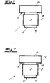
- the figures show a screw element 1 designed as a screw according to the invention, which is preferably and provided in the embodiment for the connection of a pipe 2.
- the pipeline 2 may be a motor vehicle pipeline.
- the screw fitting 1 has a Thread 3 and thread-free contact surfaces 4, 5 on.
- the unthreaded contact surface 4 is arranged at the end of the fferfittings 1 and the thread-free contact surface 5 is disposed on the threaded side underside of the screw head 6.
- the thread 3 or external thread of the screw fitting 1 is preferably and in the exemplary embodiment completely provided with a first coating 7, which has a first higher coefficient of friction ⁇ 1 .
- the two thread-free contact surfaces 4, 5 are preferably and in the exemplary embodiment completely provided with a second coating 8, which has a second lower coefficient of friction ⁇ 2 .
- the first coefficient of friction ⁇ 1 is at least five times, preferably at least six times the coefficient of friction ⁇ 2 .
- the Fig. 1 1 shows a first embodiment of a screw fitting 1 according to the invention.
- the first coating 7 with the first coefficient of friction ⁇ 1 was applied to the entire surface of the screw fitting 1. This first coating was thus applied to the thread-free contact surfaces 4, 5 in a first step.
- the first coating 7 can be applied in particular in the course of a dipping process.
- the first coating 7 is an aluminum-containing corrosion protection coating, to which at least one lubricant influencing the coefficient of friction of the coating 7 is added.
- the coefficient of friction ⁇ 1 of the first coating 7 is expediently and in this exemplary embodiment 0.33 to 0.37, for example 0.35.
- the second coating 8 with the second lower coefficient of friction ⁇ 2 is applied only to the unthreaded contact surfaces 4, 5, with the interposition of the first coating 7.
- This second coating 8 can be applied, for example, as part of a spraying process.
- the coefficient of friction of second coating 8 may preferably and in this embodiment 0.03 to 0.07 and, for example 0.05.
- a (separate) corrosion protection coating 9 is applied to the entire surface of the screw fitting 1.
- This corrosion protection coating is expediently and in the exemplary embodiment an electrolytically applied zinc-nickel corrosion protection coating.
- the first coating 7 with the first higher coefficient of friction ⁇ 1 in the region of the thread 3 is applied to the anti-corrosion coating 9.
- the first coating 7 then forms the outer surface of the screw fitting 1 in the region of the thread 3.
- the second coating 8 with the second lower coefficient of friction ⁇ 2 is applied to the corrosion protection coating 9 in the area of the unthreaded contact surfaces 4, 5.
- the second coating 8 then forms the outer surface of the screw fitting 1 in the area of the unthreaded contact surfaces 4, 5.
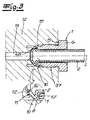
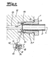
- the Figures 3 and 4 show a screw according to the invention 1 in the operating condition or a pipe connection device according to the invention with a screw according to the invention 1.
- a pipe 2 passes through the screw 1 in the axial direction.
- the pipe 2 has at one end a front element, which is formed in the embodiment as a flange 10. It is within the scope of the invention that it is a metallic bead 10, which is preferably integrally formed in the embodiment of the pipe end.
- the screw fitting 1 is in the embodiment of the Fig. 3 and 4 screwed into a formed as a terminal block 12 connecting element, which terminal block 12 has an integrated second pipe 13.
- the screw fitting 1 presses the flange 10 with its front-side sealing surface 11 against a connection surface 14 of the connection block 12.
- the screw fitting 1 is used with its thread 3 or external thread screwed into the blind bore 15 of the terminal block 12. It is understood that the blind bore 15 has a corresponding complementary internal thread.
- the thread 3 or external thread of the screw fitting 1 is provided with the first coating 7.
- the thread-free contact surface 4 at the end of the sterfittings 1 has the second coating 8.
- the flare 10 of the pipe end is an F-flare whose flare back is arranged transversely or perpendicular to the pipe longitudinal axis.
- the provided with the second coating 8 Stimende the SSfittings 1 has a complementary perpendicular to the pipe longitudinal axis L arranged surface portion 17 which rests positively against the crimp back of the F-flare.
- the flare 10 of the pipe end is an E-flare
- the flare back is cone-shaped.
- the Stimende of the associated screw fitting 1 has a conical surface portion 18 which rests positively against the crimp back of the E-flare.
- the second coating 8 is provided in the area of the positive engagement of the flange 10 in both the embodiment according to Fig. 3 as well as in the embodiment Fig. 4 .
Description
Die Erfindung betrifft ein Schraubelement, insbesondere für den Anschluss bzw. für die Verbindung von Rohrleitungen, vorzugsweise von Kraftfahrzeugrohrleitungen, wobei ein Gewinde vorgesehen ist, sowie zumindest eine gewindefreie Kontaktfläche. Die Erfindung betrifft fernerhin eine Rohranschlusseinrichtung für den Anschluss von Rohrleitungen, insbesondere von Kraftfahrzeugrohrleitungen mit einem solchen Schraubelement.The invention relates to a screw, in particular for the connection or for the connection of pipes, preferably of motor vehicle piping, wherein a thread is provided, as well as at least one thread-free contact surface. The invention further relates to a pipe connection device for the connection of pipes, in particular motor vehicle piping with such a screw.
Schraubelemente bzw. Rohranschlusseinrichtungen der vorstehend beschriebenen Art sind aus der Praxis in verschiedenen Ausführungsformen bekannt. Insbesondere sind als Schraubfittings ausgebildete Schraubelemente bekannt, mit denen eine Rohrleitung, insbesondere eine Kraftfahrzeugrohrleitung an ein Anschlusselement anschließbar ist. Diese bekannten Schraubfittings sind in der Regel mit einer Beschichtung, insbesondere mit einer Korrosionsschutzbeschichtung versehen, die normalerweise den gesamten Fitting bedeckt. Die Beschichtung wird beispielsweise im Tauchverfahren oder Sprühverfahren aufgebracht. Bei Schraubverbindungen mit diesen bekannten Schraubfittings kann es zu einem unerwünschten Lockern oder sogar Lösen der Schraubverbindung kommen. Das gilt insbesondere für Schraubfittings mit angeschlossenen Rohrleitungen. Beim Verschrauben solcher Schraubfittings kann es zu einem Mitdrehen der Rohrleitung kommen und durch eine Torsion der Rohrleitung wird Federkraft gleichsam in der Rohrleitung gespeichert. Die Torsion der Rohrleitung erzeugt ein Rückdrehmoment, das zu einem unerwünschten bzw. unkontrollierten Lockern bzw. Lösen der Schraubverbindung führen kann. Ein unerwünschtes Lockern oder Lösen der Schraubverbindung kann insbesondere auch durch Vibrationen hervorgerufen werden, wie sie beispielsweise in Kraftfahrzeugen auftreten.Screw elements or pipe connection devices of the type described above are known from practice in various embodiments. In particular, designed as a screw fittings screw elements are known, with which a pipe, in particular a motor vehicle pipeline can be connected to a connection element. These known Schraubfittings are usually provided with a coating, in particular with an anti-corrosion coating, which normally covers the entire fitting. The coating is applied, for example, by dipping or spraying. With screwed connections with these known screwed fittings, unwanted loosening or even loosening of the screw connection can occur. This applies in particular to screw fittings with connected pipelines. When screwing such screw fittings may lead to co-rotation of the pipeline and by a twist of the pipeline spring force is stored as it were in the pipeline. The torsion of the pipe generates a return torque, which can lead to an unwanted or uncontrolled loosening or loosening of the screw connection. An undesirable loosening or loosening of the screw connection can in particular also be caused by vibrations, as occur, for example, in motor vehicles.
Es sind auch Schraubelemente bzw. Schraubfittings bekannt, die im Bereich ihres Gewindes mit einer Adhäsivbeschichtung versehen sind. Dadurch wird der Schraubfitting nach dem Verschrauben fixiert und ein unerwünschtes Lockern bzw. Lösen der Schraubverbindung kann zumindest weitgehend vermieden werden. Solche Adhäsivbeschichtungen sind aber vor allem dann nicht zweckmäßig, wenn Schraubverbindungen zu einem späteren Zeitpunkt beabsichtigt wieder gelöst werden sollen.There are also known screw or screw fittings, which are provided in the region of their thread with an adhesive coating. As a result, the screw is fixed after screwing and unwanted loosening or loosening of the screw can be at least largely avoided. However, such adhesive coatings are not particularly useful when screwed at a later time intended to be solved again.
EP-A0 997 677 beschreibt ein Schraubelement für den Anschluss von Rohrleitungen.EP-A-0 997 677 describes a screw element for the connection of pipelines.
Der Erfindung liegt das technische Problem zugrunde, ein Schraubelement der eingangs beschriebenen Art anzugeben, mit dem ein unerwünschtes Lockern oder Lösen der zugeordneten Schraubverbindung auf einfache, effektive und funktionssichere Weise vermieden werden kann. Der Erfindung liegt weiterhin das technische Problem zugrunde, eine entsprechende Rohranschlusseinrichtung anzugeben.The invention is based on the technical problem of specifying a screw of the type described above, with an unwanted loosening or loosening of the associated screw can be avoided in a simple, effective and reliable manner. The invention is further based on the technical problem of specifying a corresponding pipe connection device.
Zur Lösung dieses technischen Problems lehrt die Erfindung ein Schraubelement, insbesondere für den Anschluss bzw. für die Verbindung von Rohr leitungen, vorzugsweise von Kraftfahrzeugrohrleitungen, wobei ein Gewinde vorgesehen ist sowie zumindest eine gewindefreie Kontaktfläche vorhanden ist,
wobei das Gewinde zumindest bereichsweise mit einer ersten Beschichtung versehen ist, die einen ersten Reibwert µ1 aufweist,
wobei die Kontaktfläche zumindest bereichsweise mit einer zweiten Beschichtung versehen ist, die einen zweiten Reibwert µ2 aufweist
und wobei der erste Reibwert µ1 größer ist, insbesondere deutlich größer ist als der zweite Reibwert µ2.To solve this technical problem, the invention teaches a screw, in particular for the connection or for the connection of pipe lines, preferably of motor vehicle piping, wherein a thread is provided and at least one thread-free contact surface is present,
wherein the thread is at least partially provided with a first coating having a first coefficient of friction μ 1 ,
wherein the contact surface is at least partially provided with a second coating having a second coefficient of friction μ 2
and wherein the first coefficient of friction μ 1 is greater, in particular significantly greater than the second coefficient of friction μ 2 .
Es liegt im Rahmen der Erfindung, dass die erste Beschichtung auf dem Gewinde die Außenoberfläche im Bereich des Gewindes bildet bzw. die äußerste Beschichtung des Gewindes ist. Es liegt weiterhin im Rahmen der Erfindung, dass die zweite Beschichtung auf der zumindest einen Kontaktfläche die Außenoberfläche im Bereich der Kontaktfläche bildet bzw. die äußerste Beschichtung der Kontaktfläche ist. Zweckmäßigerweise ist das Gewinde vollständig bzw. im Wesentlichen vollständig mit der ersten Beschichtung versehen. Vorzugsweise ist die Kontaktfläche vollständig bzw. im Wesentlichen vollständig mit der zweiten Beschichtung versehen. Es liegt im Übrigen im Rahmen der Erfindung, dass die erste Beschichtung keine Adhäsivbeschichtung ist.It is within the scope of the invention that the first coating on the thread forms the outer surface in the region of the thread or is the outermost coating of the thread. It is also within the scope of the invention that the second coating on the at least one contact surface forms the outer surface in the region of the contact surface or the outermost coating of the contact surface is. Conveniently, the thread is completely or substantially completely provided with the first coating. Preferably, the contact surface is completely or substantially completely provided with the second coating. Incidentally, it is within the scope of the invention that the first coating is not an adhesive coating.
Nach sehr bevorzugter Ausführungsform, der im Rahmen der Erfindung besondere Bedeutung zukommt, ist das Schraubelement ein Schraubenbolzen bzw. ein Schraubfitting, der ein als Außengewinde ausgebildetes Gewinde aufweist. Dann ist dieses Außengewinde des Schraubenbolzens bzw. Schraubfittings zumindest bereichsweise und vorzugsweise vollständig bzw. im Wesentlichen vollständig mit der ersten Beschichtung versehen. Nach einer empfohlenen Ausführungsform handelt es sich bei dem Schraubelement um einen Schraubfitting, an den eine Rohrleitung angeschlossen ist. Gemäß bevorzugter Ausführungsform durchgreift die Rohrleitung den Schraubfitting in Axialrichtung und hintergreift das Stimende des Schraubfittings mit einem Rohrleitungsende. Das Rohrleitungsende ist dabei empfohlenermaßen als Bördel ausgebildet. Die Ausführungsform mit dem Schraubfitting bzw. weitere diesbezügliche Ausführungsvarianten werden weiter unten noch näher erläutert.After a very preferred embodiment, which is of particular importance in the context of the invention, the screw is a bolt or a screw fitting having a thread formed as an external thread. Then this external thread of the screw bolt or screw fitting is at least partially and preferably completely or substantially completely provided with the first coating. According to a recommended embodiment, the screw element is a screw fitting to which a pipeline is connected. According to a preferred embodiment, the pipe passes through the screw fitting in the axial direction and engages behind the end of the screw fitting with a pipe end. The end of the pipe is recommended designed as a crimp. The embodiment with the screw fitting or other related embodiments will be explained in more detail below.
Es empfiehlt sich, dass die zumindest eine gewindefreie Kontaktfläche bzw. die gewindefreien Kontaktflächen des Schraubelementes senkrecht bzw. quer oder im Wesentlichen senkrecht bzw. im Wesentlichen quer zur Einschraubrichtung des Schraubelementes orientiert sind. Gemäß empfohlener Ausführungsform weist das Stimende des Schraubenbolzens bzw. Schraubfittings eine gewindefreie Kontaktfläche auf, die zumindest bereichsweise mit der zweiten Beschichtung mit dem zweiten Reibwert µ2 beschichtet ist. Zweckmäßigerweise ist diese gewindefreie Kontaktfläche am Stimende des Schraubenbolzens bzw. Schraubfittings vollständig mit der zweiten Beschichtung versehen bzw. beschichtet.It is recommended that the at least one unthreaded contact surface or the unthreaded contact surfaces of the screw are oriented perpendicular or transversely or substantially perpendicular or substantially transversely to the screwing of the screw. According to the recommended embodiment has the Stimende of the bolt or screw fitting on a thread-free contact surface, which is at least partially coated with the second coating with the second coefficient of friction μ 2 . Conveniently, this thread-free contact surface is completely provided or coated at the end of the screw or Schraubfittings with the second coating.
Es liegt weiterhin im Rahmen der Erfindung, dass der Schraubenbolzen bzw. Schraubfitting einen Schraubenkopf aufweist und dass die gewindeseitige Unterseite des Schraubenkopfs eine gewindefreie Kontaktfläche aufweist, die zumindest bereichsweise mit der zweiten Beschichtung mit dem zweiten Reibwert µ2 beschichtet ist. Zweckmäßigerweise ist diese gewindefreie Kontaktfläche an der Unterseite des Schraubenkopfes vollständig bzw. im Wesentlichen vollständig mit der zweiten Beschichtung versehen.It is also within the scope of the invention that the screw or screw fitting has a screw head and that the thread-side underside of the screw head has a thread-free contact surface which is at least partially coated with the second coating with the second coefficient of friction μ 2 . Appropriately, this thread-free contact surface on the underside of the screw head is completely or substantially completely provided with the second coating.
Nach einer Ausführungsform der Erfindung ist das Schraubelement eine Schraubenmutter, die ein als Innengewinde ausgebildetes Gewinde aufweist. Dann ist dieses Innengewinde zumindest bereichsweise und vorzugsweise vollständig bzw. im Wesentlichen vollständig mit der ersten Beschichtung beschichtet. Die Schraubenmutter dient zur Aufnahme eines Schraubenbolzens bzw. Schraubfittings und empfohlenermaßen zur Aufnahme eines erfindungsgemäß beschichteten Schraubenbolzens bzw. Schraubfittings. Bei der Schraubenmutter kann es sich um eine Anschlussmuffe mit Innengewinde zur Verbindung zweier Rohrleitungen handeln oder um eine Sackbohrung mit Innengewinde in einem Anschlussblock für eine anzuschließende Rohrleitung. Es liegt im Rahmen der Erfindung, dass ein Kontaktflansch der Anschlussmuffe eine gewindefreie Kontaktfläche aufweist/ist, die dann zumindest bereichsweise und vorzugsweise vollständig bzw. im Wesentlichen vollständig mit der zweiten Beschichtung versehen ist. Gemäß einer Ausführungsform der Erfindung ist sowohl ein Schraubenbolzen bzw. Schraubfitting erfindungsgemäß beschichtet als auch eine dem Schraubenbolzen zugeordnete Schraubenmutter erfindungsgemäß beschichtet.According to one embodiment of the invention, the screw is a nut having a thread formed as an internal thread. Then this internal thread is at least partially and preferably completely or substantially completely coated with the first coating. The nut serves to receive a bolt or Schraubfittings and recommended for receiving a coated according to the invention bolt or Schraubfittings. The nut may be an internally threaded connection sleeve for connecting two pipes or an internally threaded blind hole in a connection block for a pipe to be connected. It is within the scope of the invention that a contact flange of the connection sleeve has a thread-free contact surface, which is then at least partially and preferably completely or substantially completely provided with the second coating. According to one embodiment of the invention, both a screw bolt or screw fitting is coated according to the invention as well as a screw bolt associated nut according to the invention coated.
Vorteilhafterweise beträgt der erste Reibwert µ1 zumindest das Doppelte, vorzugsweise zumindest das Dreifache und besonders bevorzugt zumindest das Vierfache des zweiten Reibwertes µ2. Gemäß einer Ausführungsform beträgt der erste Reibwert µ1 zumindest das Fünffache des zweiten Reibwertes µ2.Advantageously, the first coefficient of friction μ 1 is at least twice, preferably at least three times and particularly preferably at least four times the second coefficient of friction μ 2 . According to one embodiment, the first coefficient of friction μ 1 is at least five times the second coefficient of friction μ 2 .
Eine Ausführungsvariante des erfindungsgemäßen Schraubelementes ist dadurch gekennzeichnet, dass die erste Beschichtung mit dem ersten Reibwert µ1 sowohl auf das Gewinde als auch auf die zumindest eine gewindefreie Kontaktfläche aufgebracht ist und dass die zweite Beschichtung mit dem zweiten Reibwert µ2 auf die zumindest eine gewindefreie Kontaktfläche - die erste Beschichtung dort überdeckend - aufgebracht ist. Zunächst wird also das gesamte Schraubelement oder zumindest das Gewinde und die gewindefreien Kontaktflächen des Schraubelementes mit der ersten Beschichtung versehen und dann wird die zweite Beschichtung im Bereich der gewindefreien Kontaktfläche bzw. im Bereich der gewindefreien Kontaktflächen auf die erste Beschichtung aufgebracht, so dass die zweite Beschichtung die Außenoberfläche an den gewindefreien Kontaktflächen bildet. Die erste Beschichtung wird bei dieser Ausführungsform zweckmäßigerweise durch ein Tauchverfahren aufgebracht. Die zweite Beschichtung kann im Zuge eines Sprühverfahrens aufgebracht werden.A variant of the screw element according to the invention is characterized in that the first coating with the first coefficient of friction μ 1 is applied to both the thread and the at least one thread-free contact surface and that the second coating with the second coefficient of friction μ 2 on the at least one thread-free contact surface - the first coating covering there - is applied. First, therefore, the entire screw element or at least the thread and the unthreaded contact surfaces of the screw is provided with the first coating and then the second coating is applied to the first coating in the area of the unthreaded contact surface or in the area of the unthreaded contact surfaces, so that the second coating the outer surface forms at the thread-free contact surfaces. The first coating is suitably applied in this embodiment by a dipping process. The second coating can be applied as part of a spraying process.
Eine andere Ausführungsform der Erfindung ist dadurch gekennzeichnet, dass die erste Beschichtung mit dem ersten Reibwert µ1 lediglich auf das Gewinde zumindest bereichsweise aufgebracht ist und dass die zweite Beschichtung mit dem zweiten Reibwert µ2 lediglich auf die zumindest eine gewindefreie Kontaktfläche aufgebracht ist. Bei dieser Ausführungsform wird also die erste Beschichtung lediglich auf das Gewinde und nicht auf die zumindest eine gewindefreie Kontaktfläche aufgebracht und die zweite Beschichtung wird auf die zumindest eine gewindefreie Kontaktfläche ohne Zwischenschaltung der ersten Beschichtung aufgebracht. Bei dieser Ausführungsform können die erste und die zweite Beschichtung beispielsweise jeweils im Zuge eines Sprühverfahrens aufgebracht werden.Another embodiment of the invention is characterized in that the first coating with the first coefficient of friction μ 1 is applied at least partially to the thread and that the second coating with the second coefficient of friction μ 2 is applied only to the at least one thread-free contact surface. In this embodiment, therefore, the first Coating applied only to the thread and not on the at least one thread-free contact surface and the second coating is applied to the at least one thread-free contact surface without interposition of the first coating. In this embodiment, the first and the second coating, for example, each be applied in the course of a spraying process.
Gemäß einer empfohlenen Ausführungsvariante handelt es sich bei der ersten Beschichtung um eine aluminiumhaltige Korrosionsschutzbeschichtung, die zumindest ein den Reibwert der Beschichtung erhöhendes Gleitmittel aufweist bzw. enthält. - Vorzugsweise weist die zweite Beschichtung zumindest ein den Reibwert der Beschichtung erniedrigendes Gleitmittel auf und dieses Gleitmittel ist zweckmäßigerweise Polytetrafluorethylen (PTFE) und/oder Molybdändisulfid (MoS2).According to a recommended embodiment variant, the first coating is an aluminum-containing corrosion protection coating which has or contains at least one lubricant which increases the coefficient of friction of the coating. Preferably, the second coating has at least one lubricant which reduces the coefficient of friction of the coating, and this lubricant is expediently polytetrafluoroethylene (PTFE) and / or molybdenum disulfide (MoS 2 ).
Empfohlenermaßen beträgt der Reibwert µ1 der ersten Beschichtung 0,15 bis 0,5, vorzugsweise 0,2 bis 0,45 und bevorzugt 0,25 bis 0,4. Ein Reibwert µ1 zwischen 0,3 und 0,4, beispielsweise 0,35 hat sich bewährt. - Es empfiehlt sich, dass der Reibwert µ2 der zweiten Beschichtung 0,02 bis 0,2, vorzugsweise 0,02 bis 0,15 und bevorzugt 0,03 bis 0,1 beträgt. Es hat sich bewährt, dass der Reibwert µ2 der zweiten Beschichtung zwischen 0,03 und 0,08 liegt und beispielsweise 0,05 beträgt.The coefficient of friction μ 1 of the first coating is preferably 0.15 to 0.5, preferably 0.2 to 0.45 and preferably 0.25 to 0.4. A coefficient of friction μ 1 between 0.3 and 0.4, for example 0.35, has proven itself. It is recommended that the coefficient of friction μ 2 of the second coating is 0.02 to 0.2, preferably 0.02 to 0.15 and preferably 0.03 to 0.1. It has been proven that the coefficient of friction μ 2 of the second coating is between 0.03 and 0.08 and, for example, is 0.05.
Zweckmäßigerweise beträgt die Schichtdicke der ersten Beschichtung 2 µm bis 25 µm und vorzugsweise 3 µm bis 20 µm. - Empfohlenermaßen beträgt die Schichtdicke der zweiten Beschichtung 5 µm bis 25 µm und bevorzugt 5 µm bis 20 µm.The layer thickness of the first coating is expediently from 2 μm to 25 μm and preferably from 3 μm to 20 μm. - Empfohlenermaßen the layer thickness of the second coating is 5 microns to 25 microns and preferably 5 microns to 20 microns.
Gegenstand der Erfindung ist auch eine Rohranschlusseinrichtung für den Anschluss von Rohrleitungen, insbesondere von Kraftfahrzeugrohrleitungen, wobei die Rohranschlusseinrichtung ein erfindungsgemäßes Schraubelement aufweist und wobei an dieses Schraubelement eine Rohrleitung angeschlossen ist. Das Schraubelement mit der angeschlossenen Rohrleitung ist an ein Anschlusselement durch Verschraubung anschließbar. Gemäß einer bevorzugten Ausführungsform handelt es sich bei dem vorgenannten Schraubelement um einen Schraubenbolzen oder um einen Schraubfitting mit angeschlossener Rohrleitung. Das Anschlusselement kann dann eine Anschlussmuffe mit angeschlossener zweiter Rohrleitung sein. Die Schraubverbindung dient dann also zur Verbindung zweier Rohrleitungen, insbesondere Kraftfahrzeugrohrleitungen. Wie oben bereits dargelegt, kann es sich bei dem Anschlusselement auch um eine Sackbohrung in einem Anschlussblock handeln, in die der Schraubenbolzen bzw. der Schraubfitting mit der angeschlossenen Rohrleitung einschraubbar ist.The invention also relates to a pipe connection device for the connection of pipelines, in particular of motor vehicle pipelines, wherein the pipe connection device has a screw element according to the invention and wherein a pipe is connected to this screw element. The screw with the connected pipe can be connected to a connection element by screwing. According to a preferred embodiment, the aforementioned screw element is a screw bolt or a screw fitting with a connected pipe. The connection element can then be a connection sleeve with a connected second pipeline. The screw connection then serves to connect two pipes, in particular motor vehicle pipelines. As already explained above, the connecting element can also be a blind bore in a connection block, into which the screw bolt or the screw fitting with the connected pipeline can be screwed.
Eine besonders bevorzugte Ausführungsform der Erfindung ist dadurch gekennzeichnet, dass das Schraubelement ein Schraubfitting mit einer Axialbohrung ist, welche Axialbohrung von der Rohrleitung durchfasst wird, wobei die Rohrleitung an ihrem Rohrleitungsende einen Bördel aufweist und wobei das mit der zweiten Beschichtung versehene Stimende des Schraubfittings an der Bördelrückseite des Bördels anliegt. Es liegt auch im Rahmen der Erfindung, dass die Bördelrückseite des Rohrleitungsendes mit der zweiten Beschichtung versehen ist. Es liegt weiterhin im Rahmen der Erfindung, dass das Gewinde des Schraubfittings mit der ersten Beschichtung versehen ist. Zweckmäßigerweise liegt das Stimende des Schraubfittings zumindest bereichsweise formschlüssig an der Bördelrückseite an. Nach einer Ausführungsform der Erfindung ist der Bördel am Rohrleitungsende ein F-Bördel, dessen Bördelrückseite senkrecht bzw. im Wesentlichen senkrecht zur Rohrleitungslängsachse orientiert ist und das Stimende des Schraubfittings weist dann zumindest einen senkrecht oder im Wesentlichen senkrecht zur Rohrleitungslängsachse orientierten Flächenabschnitt auf, der formschlüssig an der Bördelrückseite anliegt. Zweckmäßigerweise läuft der Flächenabschnitt über den Umfang des Schraubfittings um. Nach einer anderen Ausführungsform der Erfindung ist der Bördel am Rohrleitungsende ein E-Bördel, dessen Bördelrückseite konusförmig bzw. im Wesentlichen konusförmig ausgebildet ist und das Stimende des Schraubfittings weist zumindest einen konusförmigen oder im Wesentlichen konusförmig ausgebildeten Flächenabschnitt auf, der formschlüssig an der Bördelrückseite anliegt. Zweckmäßigerweise läuft dieser Flächenabschnitt über den Umfang des Schraubfittings um. Grundsätzlich kann der Bördel am Rohrleitungsende auch andere Formen aufweisen. In jedem Fall wird bevorzugt, dass das Stimende des Schraubfittings zumindest bereichsweise und empfohlenermaßen über den gesamten Umfang des Schraubfittings formschlüssig an der Bördelrückseite des Rohrleitungsendes anliegt.A particularly preferred embodiment of the invention is characterized in that the screw is a screw with an axial bore, which axial bore is penetrated by the pipe, wherein the pipe has a flange at its pipe end and wherein the provided with the second coating Stimende the Schraubfittings on the Bördelrückseite of the flange is applied. It is also within the scope of the invention that the crimp back of the pipe end is provided with the second coating. It is also within the scope of the invention that the thread of the screw fitting is provided with the first coating. Appropriately, the Stimende of the screw fitting is at least partially positively against the crimp back. According to one embodiment of the invention, the flare at the end of the pipe is an F-flare, the flare back is oriented perpendicular or substantially perpendicular to the pipe longitudinal axis and the Stimende of Schraubfittings then has at least one perpendicular or substantially perpendicular to the pipe longitudinal axis oriented surface portion of the form-fitting manner the crimp back rests. Conveniently, the surface section runs around the circumference of the screw fitting. According to another embodiment of the invention, the flare at the end of the pipe is an E-flare whose flare back is conical or substantially cone-shaped and the end of the Schraubfittings has at least one conical or substantially conical surface portion which rests positively on the flare back. Conveniently, this surface section runs around the circumference of the screw fitting. In principle, the flare at the end of the pipe can also have other shapes. In any case, it is preferred that the butt end of the screw fitting rests at least partially and recommended over the entire circumference of the screw fitting positively against the crimp back of the pipe end.
Gemäß einer weiteren empfohlenen Ausführungsform der Erfindung ist das Schraubelement eine Schraubenmutter mit einer Axialbohrung, welche Axialbohrung von der Rohrleitung durchfasst wird, wobei die Rohrleitung an ihrem Rohrleitungsende einen Bördel aufweist, wobei die Schraubenmutter einen mit der zweiten Beschichtung versehenen, innenseitigen Kontaktflansch aufweist und wobei der Bördel der Rohrleitung mit seiner Bördelrückseite an dem Kontaktflansch anliegt. Vorzugsweise liegt der Kontaktflansch zumindest bereichsweise und bevorzugt über den gesamten Umfang des Bördels formschlüssig an der Bördelrückseite an. Gemäß einer Ausführungsvariante ist der Bördel ein F-Bördel, dessen Bördelrückseite senkrecht oder im Wesentlichen senkrecht zur Rohrleitungslängsachse orientiert ist und der Kontaktflansch der Schraubenmutter weist zumindest einen senkrecht oder im Wesentlichen senkrecht zur Rohrleitungslängsachse orientierten Flächenabschnitt auf, der formschlüssig an der Bördelrückseite anliegt. Gemäß einer weiteren Ausführungsvariante ist der Bördel ein E-Bördel, dessen Bördelrückseite konusförmig bzw. im Wesentlichen konusförmig ausgebildet ist und der Kontaktflansch der Schraubenmutter weist zumindest einen konusförmigen oder im Wesentlichen konusförmig ausgebildeten Flächenabschnitt auf, der formschlüssig an der Bördelrückseite anliegt. Es liegt im Rahmen der Erfindung, dass die Schraubenmutter ein Innengewinde zur Aufnahme eines Anschlusselementes aufweist und dieses Innengewinde ist mit der ersten Beschichtung versehen.According to a further recommended embodiment of the invention, the screw is a nut with an axial bore, which axial bore is penetrated by the pipeline, wherein the pipe has a flange at its pipe end, wherein the nut has a provided with the second coating, inside contact flange and wherein the Bördel the pipe rests with its bead back on the contact flange. Preferably, the contact flange is at least partially and preferably over the entire circumference of the crimp on a form-fitting on the hemming back. According to one embodiment variant, the flare is an F flare whose flanged rear side is oriented perpendicularly or substantially perpendicular to the longitudinal axis of the pipe, and the contact flange of the screw nut has at least one surface section oriented perpendicularly or substantially perpendicular to the pipe longitudinal axis, which bears against the flare back side in a form-fitting manner. According to a further embodiment, the flare is an E-flare, the flare rear side is conical or substantially cone-shaped and the contact flange of the nut has at least one cone-shaped or substantially cone-shaped surface portion, which rests positively on the crimp back. It is within the scope of the invention that the nut has an internal thread for receiving a connection element and this internal thread is provided with the first coating.
Oben wurde dargelegt, dass nach einer bevorzugten Ausführungsform der Erfindung das Schraubelement ein Schraubfitting ist, und dass das Stimende des Schraubfittings im montierten Zustand der Rohranschlusseinrichtung an der Bördelrückseite des Bördels am Rohrleitungsende anliegt. Beim Anziehen des Schraubfittings übt dieser eine axiale Anpresskraft Fax auf die Bördelrückseite aus und überträgt ein Drehmoment M auf die Bördelrückseite und damit auf die Rohrleitung. Dieses Drehmoment M ist messbar. Sinn der zweiten Beschichtung am Stimende des Schraubfittings ist die Minimierung des übertragenen Drehmomentes M. Es liegt im Rahmen der Erfindung, dass mit der zweiten Beschichtung am Stimende des Schraubfittings bei einer Axialkraft von Fax = 11 kN ein Drehmoment von 0,2 bis 2,5 Nm, vorzugsweise von 0,2 bis 2,2 Nm, bevorzugt von 0,2 bis 2,0 Nm und sehr bevorzugt von 0,2 bis 1,5 Nm übertragen wird. Ohne zweite Beschichtung am Stimende des Schraubfittings wird bei einer Axialkraft von Fax = 11 kN ein Drehmoment von größer als 3 Nm bzw. deutlich größer als 3 Nm übertragen. Es versteht sich, dass das übertragene Drehmoment mit der jeweiligen Kontaktfläche zwischen Schraubfitting und Bördel zunimmt. Die vorstehend angegebenen Werte gelten insbesondere für erfindungsgemäß beschichtete metallische Schraubfittings und metallische Bördel und insbesondere für Schraubfittings mit Gewindedurchmessem zwischen 8 und 16 mm, vorzugsweise zwischen 10 und 14 mm. Die Durchmesser der zugeordneten Bördel liegen in der Größenordnung der Gewindedurchmesser.It has been explained above that according to a preferred embodiment of the invention, the screw element is a screw fitting, and that the end of the screw fitting rests on the crimp back of the flare at the pipe end in the mounted state of the pipe connection device. When tightening the screw this exerts an axial contact force F ax on the hemming back and transmits a torque M on the hemming back and thus on the pipeline. This torque M is measurable. The purpose of the second coating at the front end of the screw fitting is to minimize the transmitted torque M. It is within the scope of the invention that with the second coating at the end of the screw fitting at an axial force of F ax = 11 kN a torque of 0.2 to 2, 5 Nm, preferably from 0.2 to 2.2 Nm, preferably from 0.2 to 2.0 Nm and very preferably from 0.2 to 1.5 Nm is transmitted. Without a second coating on the end of the screw fitting, a torque of greater than 3 Nm or significantly greater than 3 Nm is transmitted at an axial force of F ax = 11 kN. It is understood that the transmitted torque increases with the respective contact surface between screw fitting and flare. The values given above apply in particular to metallic screw fittings coated according to the invention and metallic flanges and in particular to screw fittings with thread diameters between 8 and 16 mm, preferably between 10 and 14 mm. The diameters of the associated flare are in the order of the thread diameter.
Die Erfindung wird nachfolgend anhand von zwei Ausführungsbeispielen näher erläutert:
- Nach einem ersten Ausführungsbeispiel wird ein Schraubenbolzen bzw. ein Schraubfitting zunächst vollständig bzw. im Wesentlichen vollständig mit der ersten Beschichtung versehen, bei der es sich um eine Korrosionsschutzbeschichtung handelt, die empfohlenermaßen Aluminium enthält. Fernerhin enthält diese erste Beschichtung zumindest ein den Reibwert der ersten Beschichtung beeinflussendes Gleitmittel. Es empfiehlt sich, die erste Beschichtung mit einer
Schichtdicke von 10 bis 20 µm, beispielsweise 15 µm aufzubringen. Der Reibwert µ1 dieser ersten Beschichtung beträgt vorzugsweise 0,25 bis 0,45,bevorzugt 0,3bis 0,4 und beispielsweise 0,35. Anschließend wird dann die zweite Beschichtung mit dem zweiten Reibwert µ2 lediglich im Bereich der gewindefreien Kontaktflächen aufgebracht, nämlich an der Stirnendfläche des Schraubenbolzens bzw. Schraubfittings und an der gewindeseitigen Unterseite des Schraubenkopfs des Schraubenbolzens bzw. Schraubfittings. - Die zweite Beschichtung überdeckt im Bereich der gewindefreien Kontaktflächen also die erste Beschichtung. Es liegt im Rahmen der Erfindung, dass die zweite Beschichtung zumindest ein den Reibwert der Beschichtung erniedrigendes Gleitmittel aufweist. Zweckmäßigerweise handelt es sich bei diesem Gleitmittel um Polytetrafluorethylen (PTFE) und/oder Molybdändisulfid (MoS2). Empfohlenermaßen enthält die zweite Beschichtung sowohl Polytetrafluorethylen als auch Molybdändisulfid. Die zweite Beschichtung wird vorzugsweise in
einer Schichtdicke von 5bis 15 µm, beispielsweise 10 µm aufgebracht. - Der Reibwert µ2 der zweiten Beschichtung beträgt zweckmäßigerweise 0,02 bis 0.08, bevorzugt 0,03 bis 0,07 und beispielsweise 0,05.
- According to a first embodiment, a bolt or a screw fitting is first completely or substantially completely provided with the first coating, which is a corrosion protection coating, which is recommended contains aluminum. Furthermore, this first coating contains at least one lubricant which influences the coefficient of friction of the first coating. It is recommended to apply the first coating with a layer thickness of 10 to 20 μm, for example 15 μm. The coefficient of friction μ 1 of this first coating is preferably 0.25 to 0.45, preferably 0.3 to 0.4 and for example 0.35. Subsequently, the second coating with the second coefficient of friction μ 2 is then applied only in the area of the unthreaded contact surfaces, namely on the front end face of the bolt or Schraubfittings and on the threaded side underside of the screw head of the bolt or Schraubfittings.
- The second coating thus covers the first coating in the area of the unthreaded contact surfaces. It is within the scope of the invention that the second coating has at least one lubricant which reduces the coefficient of friction of the coating. Conveniently, this lubricant is polytetrafluoroethylene (PTFE) and / or molybdenum disulfide (MoS 2 ). It is recommended that the second coating contain both polytetrafluoroethylene and molybdenum disulfide. The second coating is preferably applied in a layer thickness of 5 to 15 μm, for example 10 μm.
- The coefficient of friction μ 2 of the second coating is expediently 0.02 to 0.08, preferably 0.03 to 0.07 and for example 0.05.
Im Rahmen eines zweiten Ausführungsbeispiels wird auf einen Schraubenbolzen bzw. Schraubfitting zunächst eine Korrosionsschutzbeschichtung aufgebracht. Zweckmäßigerweise wird diese Korrosionsschutzbeschichtung auf die gesamte Oberfläche des Schraubfittings aufgebracht und zwar vorzugsweise elektrolytisch. Bei der Korrosionsschutzbeschichtung handelt es sich empfohlenermaßen um eine Zink-Nickel-Beschichtung. Die Schichtdicke dieser Korrosionsschutzbeschichtung beträgt vorzugsweise 4 bis 12 µm, bevorzugt 6 bis 10 µm und beispielsweise 8 µm. Anschließend wird auf diese Korrosionsschutzbeschichtung selektiv im Bereich des Gewindes des Schraubfittings die erste Beschichtung mit dem hohen ersten Reibwert µ1 aufgebracht. Die Schichtdicke dieser ersten Beschichtung beträgt empfohlenermaßen 2 bis 8 µm, vorzugsweise 3 bis 7 µm und beispielsweise 5 µm. Es liegt im Rahmen der Erfindung, dass diese erste Beschichtung zumindest ein den Reibwert der Beschichtung beeinflussendes Gleitmittel aufweist bzw. enthält. Daraufhin wird die zweite Beschichtung mit dem zweiten niedrigeren Reibwert µ2 auf den gewindefreien Kontaktflächen aufgebracht, nämlich an der Stimendfläche des Schraubfittings und an der Unterseite des Schraubenkopfes des Schraubfittings. Die zweite Beschichtung enthält zur Herabsetzung des Reibwertes Polytetrafluorethylen (PTFE) und Molybdändisulfid (MoS2). Die Schichtdicke dieser zweiten Beschichtung beträgt zweckmäßigerweise 10 bis 20 µm, beispielsweise 15 µm. Bei diesem zweiten Ausführungsbeispiel kann auch zuerst die vorgenannte zweite Beschichtung selektiv aufgebracht werden und anschließend die vorgenannte erste Beschichtung selektiv aufgebracht werden.As part of a second embodiment, a corrosion protection coating is first applied to a bolt or screw fitting. Conveniently, this corrosion protection coating on the applied entire surface of the screw fitting and preferably electrolytically. The anti-corrosion coating is recommended to be a zinc-nickel coating. The layer thickness of this corrosion protection coating is preferably 4 to 12 .mu.m, preferably 6 to 10 .mu.m and for example 8 .mu.m. Subsequently, the first coating with the high first coefficient of friction μ 1 is selectively applied to this anticorrosion coating in the region of the thread of the screw fitting. The layer thickness of this first coating is recommended to be 2 to 8 μm, preferably 3 to 7 μm and for example 5 μm. It is within the scope of the invention that this first coating has or contains at least one lubricant which influences the coefficient of friction of the coating. Then, the second coating with the second lower coefficient of friction μ 2 is applied to the unthreaded contact surfaces, namely at the Stimendfläche the Schraubfittings and at the bottom of the screw head of the screw fitting. The second coating contains polytetrafluoroethylene (PTFE) and molybdenum disulfide (MoS 2 ) to reduce the coefficient of friction. The layer thickness of this second coating is suitably 10 to 20 microns, for example 15 microns. In this second embodiment, the aforementioned second coating can also be applied selectively first, and then the aforementioned first coating can be applied selectively.
Der Erfindung liegt die Erkenntnis zugrunde, dass aufgrund der erfindungsgemäßen Lehre bzw. aufgrund der erfindungsgemäßen Beschichtung des Schraubelementes ein unbeabsichtigtes Lockern oder Lösen der zugeordneten Schraubverbindung auf einfache Weise sowie effektiv und funktionssicher vermieden werden kann. Durch die erfindungsgemäße Aufbringung verschiedener Beschichtungen kann das erfindungsgemäße technische Problem überraschend wirksam gelöst werden. Der Erfindung liegt insoweit die Erkenntnis zugrunde, dass die Beschichtung mit hohem Reibwert im Bereich des Gewindes ein unbeabsichtigtes Lösen der Schraubverbindung effektiv erschwert. Die Beschichtung mit niedrigerem Reibwert im Bereich der Kontaktflächen verringert bzw. verhindert dagegen die Übertragung von Torsionskräften auf die zu verbindenden Teile bzw. Rohrenden. Dadurch wird also ein eingangs erläutertes Rückdrehmoment deutlich verringert oder sogar vollständig vermieden. Die gezielten Beschichtungen in verschiedenen Bereichen des Schraubelementes können auf einfache und präzise Weise vorgenommen werden, so dass der erfindungsgemäße Erfolg problemlos erzielbar ist. Die erfindungsgemäßen Schraubelemente eignen sich vor allem für die Verbindung von Rohrleitungen, insbesondere von Kraftfahrzeugrohrleitungen. Kraftfahrzeugrohrleitungen meint dabei vor allem Rohrleitungen für Kraftstoffe oder Bremsflüssigkeit.The invention is based on the finding that due to the teaching of the invention or due to the inventive coating of the screw unintentional loosening or loosening of the associated screw in a simple manner and can be effectively and reliably avoided. The inventive application of different coatings, the technical problem of the invention can be solved surprisingly effective. Insofar, the invention is based on the finding that the coating with a high coefficient of friction in the region of the thread effectively prevents inadvertent loosening of the screw connection difficult. The coating with a lower coefficient of friction in the area of the contact surfaces, on the other hand, reduces or prevents the transmission of torsional forces to the parts or pipe ends to be joined. As a result, an initially explained return torque is significantly reduced or even completely avoided. The targeted coatings in different areas of the screw can be made in a simple and precise manner, so that the inventive success is easily achieved. The screw elements according to the invention are particularly suitable for the connection of pipelines, in particular of motor vehicle pipelines. Motor vehicle piping means above all piping for fuels or brake fluid.
Nachfolgend wird die Erfindung anhand einer lediglich ein Ausführungsbeispiel darstellenden Zeichnung näher erläutert. Es zeigen in schematischer Darstellung:
- Fig. 1
- eine Ansicht eines als Schraubfitting ausgebildeten erfindungs- gemäßen Schraubelementes,
- Fig. 2
- den Gegenstand gemäß
Fig. 1 in einer anderen Ausführungsform, - Fig. 3
- eine erste Ausführungsform einer erfindungsgemäßen Rohran- schlusseinrichtung und
- Fig. 4
- den Gegenstand nach
Fig. 3 in einer zweiten Ausführungsform.
- Fig. 1
- a view of a screw according to the invention designed as a screw,
- Fig. 2
- the object according to
Fig. 1 in another embodiment, - Fig. 3
- a first embodiment of a pipe connection device according to the invention and
- Fig. 4
- the object after
Fig. 3 in a second embodiment.
Die Figuren zeigen ein als Schraubfitting 1 ausgebildetes erfindungsgemäßes Schraubelement, das vorzugsweise und im Ausführungsbeispiel für den Anschluss einer Rohrleitung 2 vorgesehen ist. Bei der Rohrleitung 2 mag es sich um eine Kraftfahrzeugrohrleitung handeln. Der Schraubfitting 1 weist ein Gewinde 3 sowie gewindefreie Kontaktflächen 4, 5 auf. Die gewindefreie Kontaktfläche 4 ist am Stimende des Schraubfittings 1 angeordnet und die gewindefreie Kontaktfläche 5 ist an der gewindeseitigen Unterseite des Schraubenkopfes 6 angeordnet. Das Gewinde 3 bzw. Außengewinde des Schraubfittings 1 ist vorzugsweise und im Ausführungsbeispiel vollständig mit einer ersten Beschichtung 7 versehen, die einen ersten höheren Reibwert µ1 aufweist. Die beiden gewindefreien Kontaktflächen 4, 5 sind vorzugsweise und im Ausführungsbeispiel vollständig mit einer zweiten Beschichtung 8 versehen, die einen zweiten niedrigeren Reibwert µ2 aufweist. Nach bevorzugter Ausführungsform und im Ausführungsbeispiel beträgt der erste Reibwert µ1 zumindest das Fünffache, vorzugsweise zumindest das Sechsfache des Reibwertes µ2.The figures show a
Die
Bei der Ausführungsform gemäß
Die
Im Ausführungsbeispiel nach
Im Ausführungsbeispiel nach
Claims (15)
- Screw element for connecting pipes (2), preferably motor vehicle pipes, a thread (3) being provided and at least one thread-free contact surface (4, 5) being present,
the thread (3) being provided at least partially with a first coating (7), which has a first coefficient of friction (µ1),
characterised in that the contact surface (4, 5) is provided at least partially with a second coating (8), which has a second coefficient of friction (µ2),
and in that the first coefficient of friction (µ1) is greater, in particular considerably greater, than the second coefficient of friction (µ2). - Screw element according to Claim 1, the screw element being a screw bolt and/or screw fitting, which has a thread (3) configured as an external thread.
- Screw element according to Claim 2, the front end of the screw bolt and/or screw fitting (1) comprising a thread-free contact surface (4, 5), which is coated at least partially with the second coating (8) having the second coefficient of friction (µ2).
- Screw element according to one of Claims 2 or 3, the screw bolt and/or screw fitting (1) comprising a screw head (6), and the underside of the screw head (6) on the thread side comprising a thread-free contact surface (4, 5) which is at least partially coated with the second coating (8) having the second coefficient of friction (µ2).
- Screw element according to Claim 1, the screw element being a screw nut, which has a thread (3) configured as an internal thread.
- Screw element according to one of Claims 1 to 5, the first coefficient of friction (µ1) being at least twice, preferably being at least three times, and particularly preferably at least four times, the second coefficient of friction (µ2).
- Screw element according to one of Claims 1 to 6, the coefficient of friction (µ1) of the first coating being 0.15 to 0.5, preferably 0.2 to 0.45 and preferably 0.25 to 0.4.
- Screw element according to one of Claims 1 to 7, the coefficient of friction (µ2) of the second coating (8) being 0.02 to 0.2, preferably 0.02 to 0.15 and preferably 0.03 to 0.1.
- Screw element according to one of Claims 1 to 8, the layer thickness of the first coating (7) being 2 µm to 25 µm and preferably 3 µm to 20 µm.
- Screw element according to one of Claims 1 to 9, the layer thickness of the second coating (8) being 5 µm to 25 µm and preferably 5 µm to 20 µm.
- Pipe connection device for connecting pipes (2), in particular motor vehicle pipes, comprising a screw element, according to one of Claims 1 to 10, a pipe (2) being connected to the screw element and the screw element being able to be connected to a connector element by a screw connection.
- Pipe connection device according to Claim 11, the screw element being a screw fitting (1) having an axial bore, which axial bore is penetrated by a pipe (2), the pipe (2) at the pipe end thereof comprising a flare (10) and the front end of the screw fitting (1) provided with the second coating (8) bearing against the rear side of the flare (10).
- Pipe connection device according to one of Claims 11 or 12, the screw element being a screw nut with an axial bore, which axial bore is penetrated by a pipe (2), the pipe (2) at the pipe end thereof comprising a flare (10), the screw nut comprising a contact flange on the inside provided with the second coating (8), and the flare (10) of the pipe (2) bearing against the contact flange with the rear flare side thereof.
- Pipe connection device according to one of Claims 11 to 13, the flare (10) being an F-flare, the rear flare side thereof being arranged perpendicular and/or substantially perpendicular to the pipe longitudinal axis (L), and the front end of the screw fitting (1) and/or the contact flange of the screw nut having at least one surface portion (17) which is oriented perpendicular and/or substantially perpendicular to the pipe longitudinal axis (L), and which bears positively against the rear flare side.
- Pipe connection device according to one of Claims 11 to 13, the flare (10) being an E-flare, the rear flare side thereof being of conical and/or substantially conical configuration, and the front end of the screw fitting (1) and/or the contact flange of the screw nut comprising at least one conically configured and/or substantially conically configured surface portion (18) which bears positively against the rear flare side.
Priority Applications (7)
| Application Number | Priority Date | Filing Date | Title |
|---|---|---|---|
| EP08010964.8A EP2136119B2 (en) | 2008-06-17 | 2008-06-17 | Pipe connection device for attaching pipes |
| DE502008001944T DE502008001944D1 (en) | 2008-06-17 | 2008-06-17 | Screw element and pipe connection device for connecting pipes |
| CN200910135140.9A CN101608722B (en) | 2008-06-17 | 2009-04-22 | Pipe connection device for attaching pipes |
| JP2009138804A JP5438387B2 (en) | 2008-06-17 | 2009-06-10 | Screw elements and devices for connecting pipes |
| BRPI0901773-9 BRPI0901773B1 (en) | 2008-06-17 | 2009-06-16 | device for connecting pipes |
| US12/486,163 US8172278B2 (en) | 2008-06-17 | 2009-06-17 | Threaded component and device for connecting piping |
| KR20090054042A KR101479351B1 (en) | 2008-06-17 | 2009-06-17 | Threaded component and device for connecting piping |
Applications Claiming Priority (1)
| Application Number | Priority Date | Filing Date | Title |
|---|---|---|---|
| EP08010964.8A EP2136119B2 (en) | 2008-06-17 | 2008-06-17 | Pipe connection device for attaching pipes |
Publications (3)
| Publication Number | Publication Date |
|---|---|
| EP2136119A1 EP2136119A1 (en) | 2009-12-23 |
| EP2136119B1 true EP2136119B1 (en) | 2010-12-01 |
| EP2136119B2 EP2136119B2 (en) | 2018-09-12 |
Family
ID=39942921
Family Applications (1)
| Application Number | Title | Priority Date | Filing Date |
|---|---|---|---|
| EP08010964.8A Active EP2136119B2 (en) | 2008-06-17 | 2008-06-17 | Pipe connection device for attaching pipes |
Country Status (7)
| Country | Link |
|---|---|
| US (1) | US8172278B2 (en) |
| EP (1) | EP2136119B2 (en) |
| JP (1) | JP5438387B2 (en) |
| KR (1) | KR101479351B1 (en) |
| CN (1) | CN101608722B (en) |
| BR (1) | BRPI0901773B1 (en) |
| DE (1) | DE502008001944D1 (en) |
Cited By (2)
| Publication number | Priority date | Publication date | Assignee | Title |
|---|---|---|---|---|
| EP2706277A2 (en) | 2012-09-10 | 2014-03-12 | Cooper-Standard Automotive (Deutschland) GmbH | Tubular screw for fixing a pipe and a method for producing such a tubular screw |
| DE202017104112U1 (en) | 2017-07-11 | 2017-07-30 | Ti Automotive (Heidelberg) Gmbh | Screw element for connection of piping and pipe connection device |
Families Citing this family (26)
| Publication number | Priority date | Publication date | Assignee | Title |
|---|---|---|---|---|
| FR2956893A1 (en) * | 2010-02-26 | 2011-09-02 | Peugeot Citroen Automobiles Sa | Device for connecting fluid pipe on case of hydraulic or pneumatic system, has fixation unit whose adapted teeth permit screwing of fixation unit by toothed wheel, where teeth form toothed wheel for engaging wheel with teeth |
| DE102010044763A1 (en) * | 2010-09-08 | 2012-03-08 | Gm Global Technology Operations Llc (N.D.Ges.D. Staates Delaware) | Pipe connection for connecting pipes of a motor vehicle, exhaust system, air intake system and motor vehicle |
| US9057397B2 (en) * | 2010-09-22 | 2015-06-16 | Mcgard Llc | Chrome-plated fastener with organic coating |
| DE202011104255U1 (en) * | 2011-08-11 | 2011-11-15 | Voswinkel Entwicklungs- Und Verwaltungs-Gmbh & Co. Kg | Screw coupling for releasably connecting high pressure hydraulic lines |
| JP5722752B2 (en) * | 2011-11-18 | 2015-05-27 | 新日鐵住金株式会社 | Tubular threaded joint with excellent high-torque fastening performance |
| JP5677635B1 (en) | 2012-05-23 | 2015-02-25 | 新日鐵住金株式会社 | Tubular threaded joint with excellent high-torque fastening performance |
| EP2679873B1 (en) * | 2012-06-29 | 2017-05-31 | TI Automotive (Heidelberg) GmbH | Connection device comprising a motor vehicle pipe and a connection fitting |
| US9291291B2 (en) | 2013-05-23 | 2016-03-22 | Ti Group Automotive Systems, Llc | Tube fitting with integrated seal |
| DE202013012239U1 (en) | 2013-10-14 | 2015-10-19 | Bant Boru Sanayi Ve Ticaret Anonim Sirketi | Expanded pipe for pipe connections and device with it |
| EP2860433B1 (en) | 2013-10-14 | 2018-12-12 | Bant Boru Sanayi Ve Ticaret Anonim Sirketi | Flared pipe connection arrangement |
| DE202014102663U1 (en) | 2014-06-06 | 2014-06-24 | Ti Automotive (Heidelberg) Gmbh | Screw element for connecting pipes and pipe connection device with this screw |
| US10072778B2 (en) * | 2015-01-08 | 2018-09-11 | Toyota Motor Engineering & Manufacturing North America, Inc. | Tube nut assembly |
| DE102015105798B4 (en) | 2015-01-23 | 2016-12-08 | Cooper-Standard Automotive (Deutschland) Gmbh | Method for producing a pipeline, in particular a brake pipe or fuel pipe for a motor vehicle, and such a pipeline |
| CN105065392A (en) * | 2015-07-23 | 2015-11-18 | 苏州纽东精密制造科技有限公司 | Elastic fastener |
| US10479339B2 (en) | 2016-01-19 | 2019-11-19 | Ford Global Technologies, Llc | Flare-type brake line assembly and method of making the same |
| DE102016210887A1 (en) | 2016-06-17 | 2017-12-21 | Cooper-Standard Automotive (Deutschland) Gmbh | Method for producing a pipeline, in particular brake pipe or fuel pipe for a motor vehicle, and such a pipeline |
| BR112018077229B1 (en) * | 2016-06-30 | 2022-06-14 | Total Sa | SYSTEM FOR CONNECTING A FIRST PIPE AND A SECOND PIPE |
| DE102017113195A1 (en) | 2017-06-14 | 2018-12-20 | Bantboru Sanayi Ve Ticaret Anonim Sirketi | Rohrverbindungsvorichtung |
| FR3069614B1 (en) * | 2017-07-28 | 2020-05-29 | Akwel Sweden Ab | THIN WALL PIPE AND ASSOCIATED MANUFACTURE |
| EP3546082B1 (en) * | 2018-03-26 | 2020-05-13 | O.N. Industries Ltd. | Pipe expanding apparatus for thin stainless steel pipe |
| JP6566376B1 (en) | 2019-02-22 | 2019-08-28 | 三桜工業株式会社 | Pipe joint, tube with pipe joint, and method of manufacturing pipe joint |
| JP7221486B2 (en) * | 2019-06-20 | 2023-02-14 | 三桜工業株式会社 | Fittings and tubes with fittings |
| JP7127760B2 (en) * | 2019-06-20 | 2022-08-30 | 三桜工業株式会社 | Pipe joint axial force measuring device and axial force measuring method |
| JP2021028535A (en) | 2019-08-09 | 2021-02-25 | 三桜工業株式会社 | Pipe joint and tube with pipe joint |
| DE102019135827A1 (en) | 2019-12-27 | 2021-07-01 | Cooper-Standard Automotive (Deutschland) Gmbh | Union screw for pipelines provided with at least one flange, in particular brake pipes |
| DE202022104716U1 (en) * | 2022-08-19 | 2022-09-05 | Ti Automotive Technology Center Gmbh | connection arrangement |
Family Cites Families (45)
| Publication number | Priority date | Publication date | Assignee | Title |
|---|---|---|---|---|
| US2518468A (en) | 1947-05-26 | 1950-08-15 | Harry E Karr | Lubricated lock nut |
| US2741288A (en) | 1950-04-15 | 1956-04-10 | Kenneth L Johnson | Thread root elastic lock means |
| US3494243A (en) † | 1967-06-28 | 1970-02-10 | Standard Pressed Steel Co | Sealing fastener |
| US3675950A (en) | 1969-11-21 | 1972-07-11 | Schlumberger Technology Corp | Articles of manufacture including cylindrical members having specially-terminated protective coatings |
| US3818525A (en) † | 1971-03-08 | 1974-06-25 | Eaton Corp | Self-locking fastener |
| DE2733802A1 (en) | 1977-07-27 | 1979-02-15 | Wuerth Adolf Schrauben | Easily fixed screw for installing chipboards - is galvanised and has thread portion coated with PTFE for good slip |
| US4268544A (en) | 1978-04-03 | 1981-05-19 | The Oakland Corporation | Method of applying friction materials to threaded article |
| US4206060A (en) | 1978-10-23 | 1980-06-03 | Sumitomo Kinzoku Kogyo Kabushiki Kaisha | Bolt and nut unit coated with lubricant |
| DE3165930D1 (en) | 1981-03-30 | 1984-10-18 | Mannesmann Ag | Method for the surface treatment of screw threads |
| JPS5921185U (en) * | 1982-07-30 | 1984-02-08 | 豊田工機株式会社 | pipe connection device |
| US4468309A (en) * | 1983-04-22 | 1984-08-28 | White Engineering Corporation | Method for resisting galling |
| DE3432001C1 (en) | 1984-08-31 | 1985-10-17 | Daimler-Benz Ag, 7000 Stuttgart | Screw having defined coefficients of friction |
| US4692988A (en) | 1986-08-19 | 1987-09-15 | Nowsco Well Service (U.K.) Limited | Screw thread protection |
| US5221170B1 (en) | 1986-09-15 | 1995-08-01 | Nylok Fastener Corp | Coated threaded fasteners |
| US4835819A (en) | 1986-09-15 | 1989-06-06 | Nylok Fastener Corporation | Coated fasteners and process for making the same |
| US5427698A (en) | 1988-12-09 | 1995-06-27 | Takata Corporation | Coating composition for lubrication |
| US5066051A (en) * | 1990-01-23 | 1991-11-19 | Cajon Company | Anti-twist coupling assembly with biasing means |
| JP2529032Y2 (en) * | 1990-05-22 | 1997-03-12 | 臼井国際産業株式会社 | Connection structure of branch pipe in high pressure fuel manifold |
| JPH06235483A (en) * | 1993-02-04 | 1994-08-23 | Hino Motors Ltd | Flare nut |
| EP0786616B9 (en) | 1994-10-04 | 2010-09-08 | NSCT Premium Tubulars B.V. | Steel pipe joint having high galling resistance and surface treatment method thereof |
| DE19507715C1 (en) † | 1995-03-07 | 1996-08-01 | Mero Werke Kg | Device for fastening component to rail-shaped support |
| US5730568A (en) | 1996-10-03 | 1998-03-24 | Mcgard, Inc. | Anti-galling fastener |
| JPH10185025A (en) * | 1996-12-26 | 1998-07-14 | Sanko Kogyo Kk | Connecting joint of container valve |
| JP3352350B2 (en) * | 1997-03-04 | 2002-12-03 | 臼井国際産業株式会社 | Common rail |
| JPH1130369A (en) * | 1997-07-14 | 1999-02-02 | Usui Internatl Ind Co Ltd | Connecting structure of outside face resin covered small diametral metallic pipe |
| DE19916860A1 (en) | 1998-04-28 | 1999-11-04 | Mcgard Inc | Fastening element for fitting wheel to motor vehicle |
| JP3307345B2 (en) * | 1998-10-29 | 2002-07-24 | トヨタ自動車株式会社 | Connection structure of tube |
| DE19854591C1 (en) * | 1998-11-26 | 2000-08-31 | Hewing Gmbh | Screw connection for pipes |
| DE10001857A1 (en) | 2000-01-18 | 2001-07-19 | Schatz Gmbh | Screw, nut or washer for screw connection has annular contact surface, protuberance surrounded by grooves |
| US6527304B1 (en) * | 2000-02-17 | 2003-03-04 | Ford Global Technologies, Inc. | Brake tube connector |
| JP4092871B2 (en) | 2000-12-04 | 2008-05-28 | 住友金属工業株式会社 | Composition for forming a lubricating coating suitable for lubricating treatment of threaded joints |
| JP3931564B2 (en) | 2001-01-25 | 2007-06-20 | 住友金属工業株式会社 | Threaded joint for steel pipes with excellent seizure resistance and rust resistance |
| AU2002248002B2 (en) | 2001-04-11 | 2004-11-11 | Nippon Steel Corporation | Threaded joint for steel pipe |
| JP3870732B2 (en) | 2001-07-25 | 2007-01-24 | 住友金属工業株式会社 | Threaded joint for steel pipes with excellent seizure resistance |
| US6729659B2 (en) * | 2001-09-11 | 2004-05-04 | Visteon Global Technologies, Inc. | Flare fitting assembly with metal-to-metal line seal |
| ES2308086T3 (en) * | 2003-10-27 | 2008-12-01 | Ti Automotive (Heidelberg) Gmbh | SCREWING UNION DEVICE FOR JOINING THE TWO-TUBE REBORED EXTREME. |
| JP4442806B2 (en) * | 2003-12-17 | 2010-03-31 | 臼井国際産業株式会社 | Anti-corrosion connection structure for metal pipes |
| JP2005337469A (en) | 2004-05-31 | 2005-12-08 | Jfe Steel Kk | Screw joint for oil well pipe |
| DE502004008971D1 (en) * | 2004-08-03 | 2009-03-26 | Ti Automotive Heidelberg Gmbh | Pipe connecting device |
| US7770935B2 (en) | 2005-01-13 | 2010-08-10 | Sumitomo Metal Industries, Ltd. | Threaded joint for steel pipes |
| AR057940A1 (en) * | 2005-11-30 | 2007-12-26 | Tenaris Connections Ag | THREADED CONNECTIONS WITH HIGH AND LOW FRICTION COATINGS |
| JP4742007B2 (en) * | 2006-10-11 | 2011-08-10 | 株式会社トープラ | Film forming agent for tapping screws, film forming method for forming a film covering the outer periphery of the tapping screw using the film forming agent, and a tapping screw with a film formed with the film forming agent |
| CN1995690B (en) * | 2006-12-25 | 2010-06-09 | 安东石油技术(集团)有限公司 | Fiber composite reinforced coupler |
| CN101125995A (en) * | 2007-09-28 | 2008-02-20 | 王新虎 | Screw thread adhesion abrasion resisting self-lubricating coating and preparation method thereof |
| US7789433B2 (en) * | 2008-12-22 | 2010-09-07 | Gm Global Technology Operations, Inc. | Tube nut assembly |
-
2008
- 2008-06-17 EP EP08010964.8A patent/EP2136119B2/en active Active
- 2008-06-17 DE DE502008001944T patent/DE502008001944D1/en active Active
-
2009
- 2009-04-22 CN CN200910135140.9A patent/CN101608722B/en active Active
- 2009-06-10 JP JP2009138804A patent/JP5438387B2/en active Active
- 2009-06-16 BR BRPI0901773-9 patent/BRPI0901773B1/en not_active IP Right Cessation
- 2009-06-17 US US12/486,163 patent/US8172278B2/en active Active
- 2009-06-17 KR KR20090054042A patent/KR101479351B1/en active IP Right Grant
Cited By (5)
| Publication number | Priority date | Publication date | Assignee | Title |
|---|---|---|---|---|
| EP2706277A2 (en) | 2012-09-10 | 2014-03-12 | Cooper-Standard Automotive (Deutschland) GmbH | Tubular screw for fixing a pipe and a method for producing such a tubular screw |
| EP2706277A3 (en) * | 2012-09-10 | 2014-05-21 | Cooper-Standard Automotive (Deutschland) GmbH | Tubular screw for fixing a pipe and a method for producing such a tubular screw |
| DE102012108433C5 (en) | 2012-09-10 | 2022-04-14 | Cooper-Standard Automotive (Deutschland) Gmbh | Pipe screw for fastening a pipeline and a method for manufacturing such a pipe screw |
| DE202017104112U1 (en) | 2017-07-11 | 2017-07-30 | Ti Automotive (Heidelberg) Gmbh | Screw element for connection of piping and pipe connection device |
| WO2019012444A1 (en) | 2017-07-11 | 2019-01-17 | Ti Automotive (Heidelberg) Gmbh | Screw element for connecting pipes and a pipe connecting device |
Also Published As
| Publication number | Publication date |
|---|---|
| KR101479351B1 (en) | 2015-01-05 |
| JP2009299895A (en) | 2009-12-24 |
| EP2136119A1 (en) | 2009-12-23 |
| BRPI0901773B1 (en) | 2019-12-10 |
| BRPI0901773A2 (en) | 2010-04-13 |
| CN101608722B (en) | 2014-08-27 |
| KR20090131271A (en) | 2009-12-28 |
| JP5438387B2 (en) | 2014-03-12 |
| CN101608722A (en) | 2009-12-23 |
| EP2136119B2 (en) | 2018-09-12 |
| US8172278B2 (en) | 2012-05-08 |
| DE502008001944D1 (en) | 2011-01-13 |
| US20090324363A1 (en) | 2009-12-31 |
Similar Documents
| Publication | Publication Date | Title |
|---|---|---|
| EP2136119B1 (en) | Screwing element and pipe connection device for attaching pipes | |
| EP1624183B1 (en) | Duct connection arrangement | |
| DE102012108433B3 (en) | Pipe screw for fixing a pipeline and a method for producing such a pipe screw | |
| DE19511063C2 (en) | Pipe connection with a pipe with a connecting section and method for producing the same | |
| EP3034922B1 (en) | Screw connection device for conduits, in particular for motor vehicle conduits | |
| DE202017104112U1 (en) | Screw element for connection of piping and pipe connection device | |
| DE102015105798B4 (en) | Method for producing a pipeline, in particular a brake pipe or fuel pipe for a motor vehicle, and such a pipeline | |
| EP2665920A1 (en) | Fuel injection valve with an improved high-pressure connection | |
| DE2911919A1 (en) | SCREW CONNECTION DEVICE FOR IN PARTICULAR TUBES | |
| WO2013139641A1 (en) | Mounting system for pipe screw connections having a cutting ring | |
| DE2817438A1 (en) | IC engine fuel injection line joint - has pipe end forced against washer inside nipple by tightening inner sleeve | |
| DE102006040759B3 (en) | Tolerance compensating arrangement, has compensating bushing with flange at end, and bushing resting on component in assembled condition, where bushing has inner diameter smaller than outer thread of screw | |
| DE102012000602A1 (en) | Joint device for motor vehicle, particularly ball and socket joint device, has screw connection- and loss prevention device formed by biasing force and by irregularity of thread parameter of pin thread and clamping thread | |
| DE102008027123B4 (en) | Device for attaching a component, in particular a holding bracket for ancillaries of a vehicle, in particular a utility or motor vehicle | |
| EP1857724B1 (en) | Pipe joint with a deformed pipe | |
| DE102008057425B4 (en) | pipe connection | |
| DE102009051025B4 (en) | Device and method for dismantling a connection part | |
| DE102004036518B4 (en) | Torsion-proof sealing cone connection in injection lines for fuel injection and method for their production | |
| EP3961078B1 (en) | Method for coating a screw element, screw element and pipe connection device | |
| DE102016013700A1 (en) | weld nut | |
| DE102017008990B4 (en) | Medical device having an AM component and a tubing connector and method of connecting a tubing to an AM component using a tubing connector | |
| EP1816383A1 (en) | Dry lubricated threaded joint | |
| DE102022000820A1 (en) | screwing process | |
| DE102019206173A1 (en) | Connection system | |
| EP1359317A1 (en) | Connecting device with nut having right-hand and left-hand threading |
Legal Events
| Date | Code | Title | Description |
|---|---|---|---|
| PUAI | Public reference made under article 153(3) epc to a published international application that has entered the european phase |
Free format text: ORIGINAL CODE: 0009012 |
|
| 17P | Request for examination filed |
Effective date: 20090107 |
|
| AK | Designated contracting states |
Kind code of ref document: A1 Designated state(s): AT BE BG CH CY CZ DE DK EE ES FI FR GB GR HR HU IE IS IT LI LT LU LV MC MT NL NO PL PT RO SE SI SK TR |
|
| AX | Request for extension of the european patent |
Extension state: AL BA MK RS |
|
| GRAP | Despatch of communication of intention to grant a patent |
Free format text: ORIGINAL CODE: EPIDOSNIGR1 |
|
| GRAS | Grant fee paid |
Free format text: ORIGINAL CODE: EPIDOSNIGR3 |
|
| AKX | Designation fees paid |
Designated state(s): DE FR |
|
| GRAA | (expected) grant |
Free format text: ORIGINAL CODE: 0009210 |
|
| AK | Designated contracting states |
Kind code of ref document: B1 Designated state(s): DE FR |
|
| REF | Corresponds to: |
Ref document number: 502008001944 Country of ref document: DE Date of ref document: 20110113 Kind code of ref document: P |
|
| PLBI | Opposition filed |
Free format text: ORIGINAL CODE: 0009260 |
|
| 26 | Opposition filed |
Opponent name: COOPER-STANDARD AUTOMOTIVE (DEUTSCHLAND) GMBH Effective date: 20110829 |
|
| PLAX | Notice of opposition and request to file observation + time limit sent |
Free format text: ORIGINAL CODE: EPIDOSNOBS2 |
|
| REG | Reference to a national code |
Ref country code: DE Ref legal event code: R026 Ref document number: 502008001944 Country of ref document: DE Effective date: 20110829 |
|
| PLBB | Reply of patent proprietor to notice(s) of opposition received |
Free format text: ORIGINAL CODE: EPIDOSNOBS3 |
|
| APBM | Appeal reference recorded |
Free format text: ORIGINAL CODE: EPIDOSNREFNO |
|
| APBP | Date of receipt of notice of appeal recorded |
Free format text: ORIGINAL CODE: EPIDOSNNOA2O |
|
| APAH | Appeal reference modified |
Free format text: ORIGINAL CODE: EPIDOSCREFNO |
|
| PLAB | Opposition data, opponent's data or that of the opponent's representative modified |
Free format text: ORIGINAL CODE: 0009299OPPO |
|
| R26 | Opposition filed (corrected) |
Opponent name: COOPER-STANDARD AUTOMOTIVE (DEUTSCHLAND) GMBH Effective date: 20110829 |
|
| PLAB | Opposition data, opponent's data or that of the opponent's representative modified |
Free format text: ORIGINAL CODE: 0009299OPPO |
|
| R26 | Opposition filed (corrected) |
Opponent name: COOPER-STANDARD AUTOMOTIVE (DEUTSCHLAND) GMBH Effective date: 20110829 |
|
| REG | Reference to a national code |
Ref country code: FR Ref legal event code: PLFP Year of fee payment: 9 |
|
| REG | Reference to a national code |
Ref country code: FR Ref legal event code: PLFP Year of fee payment: 10 |
|
| APBU | Appeal procedure closed |
Free format text: ORIGINAL CODE: EPIDOSNNOA9O |
|
| REG | Reference to a national code |
Ref country code: FR Ref legal event code: PLFP Year of fee payment: 11 |
|
| PUAH | Patent maintained in amended form |
Free format text: ORIGINAL CODE: 0009272 |
|
| STAA | Information on the status of an ep patent application or granted ep patent |
Free format text: STATUS: PATENT MAINTAINED AS AMENDED |
|
| 27A | Patent maintained in amended form |
Effective date: 20180912 |
|
| AK | Designated contracting states |
Kind code of ref document: B2 Designated state(s): DE FR |
|
| REG | Reference to a national code |
Ref country code: DE Ref legal event code: R102 Ref document number: 502008001944 Country of ref document: DE |
|
| P01 | Opt-out of the competence of the unified patent court (upc) registered |
Effective date: 20230524 |
|
| PGFP | Annual fee paid to national office [announced via postgrant information from national office to epo] |
Ref country code: FR Payment date: 20230623 Year of fee payment: 16 Ref country code: DE Payment date: 20230620 Year of fee payment: 16 |