EP2135993A2 - Dispositif de chauffage destiné au chauffage inductif d'un rouleau de calandre - Google Patents
Dispositif de chauffage destiné au chauffage inductif d'un rouleau de calandre Download PDFInfo
- Publication number
- EP2135993A2 EP2135993A2 EP09004425A EP09004425A EP2135993A2 EP 2135993 A2 EP2135993 A2 EP 2135993A2 EP 09004425 A EP09004425 A EP 09004425A EP 09004425 A EP09004425 A EP 09004425A EP 2135993 A2 EP2135993 A2 EP 2135993A2
- Authority
- EP
- European Patent Office
- Prior art keywords
- heating device
- inductor
- roll
- calender roll
- ribs
- Prior art date
- Legal status (The legal status is an assumption and is not a legal conclusion. Google has not performed a legal analysis and makes no representation as to the accuracy of the status listed.)
- Granted
Links
- 238000010438 heat treatment Methods 0.000 title claims description 56
- 230000006698 induction Effects 0.000 title description 2
- 230000002093 peripheral effect Effects 0.000 claims abstract description 13
- 239000004020 conductor Substances 0.000 claims description 33
- 238000001816 cooling Methods 0.000 claims description 10
- 230000001681 protective effect Effects 0.000 claims description 9
- 239000000498 cooling water Substances 0.000 claims description 5
- 230000005855 radiation Effects 0.000 claims description 3
- 239000003779 heat-resistant material Substances 0.000 claims description 2
- 230000001939 inductive effect Effects 0.000 description 14
- 239000000463 material Substances 0.000 description 11
- 238000005452 bending Methods 0.000 description 3
- 239000003302 ferromagnetic material Substances 0.000 description 2
- 230000005291 magnetic effect Effects 0.000 description 2
- 239000011248 coating agent Substances 0.000 description 1
- 238000000576 coating method Methods 0.000 description 1
- 230000001419 dependent effect Effects 0.000 description 1
- 230000000694 effects Effects 0.000 description 1
- 239000012799 electrically-conductive coating Substances 0.000 description 1
- 230000001771 impaired effect Effects 0.000 description 1
- 238000000034 method Methods 0.000 description 1
- 230000035515 penetration Effects 0.000 description 1
- 230000035945 sensitivity Effects 0.000 description 1
- 125000006850 spacer group Chemical group 0.000 description 1
- 229910001220 stainless steel Inorganic materials 0.000 description 1
- 239000010935 stainless steel Substances 0.000 description 1
- XLYOFNOQVPJJNP-UHFFFAOYSA-N water Substances O XLYOFNOQVPJJNP-UHFFFAOYSA-N 0.000 description 1
- 238000003466 welding Methods 0.000 description 1
Images

Classifications
-
- D—TEXTILES; PAPER
- D21—PAPER-MAKING; PRODUCTION OF CELLULOSE
- D21G—CALENDERS; ACCESSORIES FOR PAPER-MAKING MACHINES
- D21G1/00—Calenders; Smoothing apparatus
- D21G1/02—Rolls; Their bearings
- D21G1/0253—Heating or cooling the rolls; Regulating the temperature
- D21G1/028—Heating or cooling the rolls; Regulating the temperature using electrical means
Definitions
- the invention relates to a heating device for inductive heating of a calender roll according to the preamble of claim 1.
- the calender roll serves to form a nip with, as a rule, another roller.
- the nip guides a material web, in particular a paper or board web.
- the material web is subjected to elevated pressure and in many cases also to elevated temperature.
- elevated temperature is normally provided by the heating of a calender roll, the so-called thermo roll.
- the calender roll is supplied to this heat transfer medium.
- the achievable working temperature is set a limit that ranges from 230 ° C to 250 ° C is.
- the inductor arrangement preferably has at least one conductor loop with two conductors which extend axially parallel to the roller.
- the two conductors are in each case in the opposite direction of current, preferably alternating current flows through. These currents then induce a magnetic field that is in the electrically conductive Concentrated deposit and generated there the eddy currents.
- Another disadvantage here is that the heating is not sufficiently uniform.
- the object of the invention is therefore to provide a heating device for inductive heating of a calender roll, which allows improved heating of the surface of the working roll circumference of the calender roll.
- a heating device for inductive heating of a calender roll is provided, with a uniform heating of the calender roll is possible with little effort.
- the inductor device or an inductor is held straight with high accuracy to the roller. Local deviations from the straightness of the inductor, which would lead to disturbances of the temperature distribution in the surface of the thermo roll, are avoided.
- the temperature distribution in the surface of the calender roll is markedly improved by reducing the influence of thermal expansion of the supporting parts of the inductor arrangement, caused by heat radiation and / or convection from the heated calender roll.
- deviations from the straightness of the inductor are minimized.
- the distance sensitivity of the inductor to the calender roll According to the invention, attention is paid to the fact that the inductor remains straight to the roll circumference practically independent of the respective operating conditions in order to avoid undesired side effects. By a Querverschiebige the inductor with respect to the support beam, this expansion, so that bending of the same is avoided.
- the inductor is held parallel to the calender roll.
- the inductor can be mounted transversely displaceable on the ribs and / or the ribs can be formed tiltable.
- the ribs preferably form spacers for the support beam relative to the calender roller for reducing the heat radiation and / or convection on the support beam.
- the ribs are preferably thin and long compared to the thickness of a conductor.
- the inductor preferably has at least one current loop which extends parallel to the axis of the calender roll. The inductor then passes a roller length of the calender roll over the shortest possible distance.
- the inductor may comprise a current conductor which is a fully-jacketed electrically conductive body.
- a conductor can be used for supercalendering of paper or board webs.
- the conductor may be formed as a waveguide, which may also be cooled, for heating the peripheral surface to temperatures above 300 ° C, in particular 350 ° C to 400 ° C, which are used for example in a Langnipkalandr Schl with a shoe calender.
- the Induktur can be formed for adjusting a power line profile along the calender roll, whereby the edge regions of the calender roll in the nip other Heat quantities can be transmitted as middle ranges.
- the support beam may be cooled to reduce the thermal expansion thereof by heat radiated from integrated supply units of the inductor device.
- a protective cover may be provided which forms a heat shield for the inductor and the support beam.
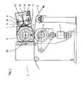
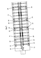
- Fig. 1 shows a heating device 1 for inductive heating of a circulating in a roller assembly 2 calender roll 3.
- the calender roll 3 has at least one electrically conductive peripheral surface, which preferably consists of ferro-magnetic material.
- Such a calender roll 3 interacts with another calender roll 4 and forms with it a nip 5, through which a material web 6 is guided.
- the material web 6 is subjected to elevated pressure, for which purpose a loading cylinder 7 may be provided, for example, which presses the other calender roll 4 against the heatable calender roll 3.
- the material web 6 is also subjected to an elevated temperature, for which purpose the calender roll 3 can be heated via the heating device 1.
- the roll assembly 2 may be a calender with hard and soft rolls to form soft nips.
- the number of rolls is selectable and is preferably 2 to 8 rolls in a roll stack.
- the heating device 1 By means of the heating device 1, the hard and / or soft rolls of a roll arrangement 2 can be heated.
- the inductive heating of roll surfaces requires so far only that at least the surface of the roll circumference of the calender roll 3 is electrically conductive.
- the calender roll 3 may form an end roll or a center roll in a roll stack. When used as a center roller such a calender roll 3 is rolled over twice, ie forms two nips, through which the material web 6 is guided.
- the nip 5 can be designed as a hard or soft nip with Nip lengths up to usually 10 mm or as a long nip with Niperyn of usually 40 to 300 mm. Nipronin of over 300 mm are also feasible depending on the use of shoe and belt techniques.
- the material web 6 is preferably a paper or board web, which is smoothed and compacted in the nip 5.
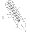
- the inductor assembly 8 comprises for this purpose a support beam 10, on which a along a roller length L (see. Fig. 6 ) of the calender roll 3 extending inductor 11 is arranged.
- the support beam 10 has a plurality of individual mutually spaced, the calender roll 3 zugestter ribs 12.
- the ribs 12 are fixed to the support beam 10 with a ribbed foot 13 or formed integrally therewith. At the free ends 14 of the ribs 12, the inductor 11 is supported transversely to the support beam 10 from.
- the support beam 10 is preferably made of non-ferromagnetic material, such as stainless steel V4A.
- the support beam 10 is also preferably designed as a hollow bar, which is preferably positioned as a spar axially parallel to the calender roll 3.
- the functional components and supply units for the inductor 11 may be housed. These are, in particular, a generator 15 for the inductor device 11 and cooling devices 16, 17, which can serve to cool the support beam 10 and / or the inductor device 11.
- cooling lines 18 may be performed on the ribbed feet 13 facing wall of the support beam 10.
- a cooling of the support beam 10 from the inside with, for example, water promotes that the support beam 10 remains as straight and stable as possible regardless of the respective temperature changes.
- For the cooling cooling water connections 26 may be provided, as in Fig. 1 shown.
- the ribs 12 are preferably made of a heat-resistant material and form support elements for the inductor 11, called inductor short.
- the ribs 12 form a comb-like (see. Fig. 2 and Fig. 6 ) or rake-type front of the support beam 10.
- the ribs 12 space the support beam 10 with respect to the calender roll 3.
- the ribs 12 are thus distance sensors.
- the ribs 12 are thus provided to keep the preferably cooled support beam 10 from the calender roll 3 at a distance and to reduce the heating of the support beam 10 by the calender roll 3.
- the ribs 12 are made of a material that can not be heated by induction.
- the inductor device 11 is arranged perpendicular to the ribs 12, in such a way that, for example, the inductor device 11 is mounted transversely displaceable on the ribs 12. For this purpose, a frictional connection between the inductor 11 and the ribs 12 is provided.
- Such attachment of the inductor device 11 to the ribs 12 may be formed using spring elements 19 as a preloaded attachment, which enables a non-positive, position-displaceable connection between ribs 12 and inductor device 11.
- the inductor device 11 can then expand freely.
- the ribs 12 are therefore preferably transverse to the roll axis of the calender roll 3 and the inductor 11 is preferably arranged axially parallel.
- the ribs 12 are formed so thin that they form bending discs that can perform an elastic tilting movement under load.
- the fin height is preferably a multiple of the thickness of an electrical conductor 20 of the inductor device 11.
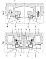
- the inductor 11 forms with the calender roll 3 at its peripheral portion 9 an air gap 21 in the range of 3 to 50 mm. Adjacent to this air gap 21, the inductor device 11 is positioned with at least one loop-shaped conductor.
- the loop-shaped conductor has two electrical conductors 20, which are traversed in the opposite direction by current.
- the two electrical conductors 20 extend parallel to the roll axis 22 of the calender roll 3.
- the current is an alternating current.
- the currents flowing through the two electrical conductors 20 generate a magnetic field which is closed by the peripheral portion 9 of the electrically conductive peripheral surface of the calender roll 3 and causes therein to be heated by induced currents.
- the number and arrangement of the conductors 20 depends on the needs.
- the penetration depth of the heating in the electrically conductive peripheral region of the calender roll 3 can be controlled.
- the electrically conductive peripheral surface of the calender roll 3 may be formed by an electrically conductive coating, which was applied in particular by build-up welding on a hollow roll body.
- the calender roll 3 can also be equipped as a bending compensating roll with inner support elements. Additionally or alternatively, the calender roll 3 may be formed with channels for the passage of a heat transfer medium in order to carry out a basic heating in a conventional manner.
- the electrical conductor 20 is an electrically conductive body in the form of a waveguide.
- the waveguide-shaped conductor 20 allows a passage of cooling water. This is the case in particular for high power outputs.
- the at least two waveguide-shaped conductors 20 are connected to cooling lines 23 for this purpose.
- a plurality of cooling-water connections 24 can be provided for segment-wise cooling of the conductor (s) 20.
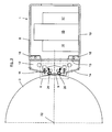
- Fig. 7 shows the inductor 11 may be formed to adjust a power line profile along the calender roll 3.
- the edge region of the calender roll 3 may be assigned a further inductor loop 25, which form the inductor device 11 with the conductors 20.
- a protective cover 28 is preferably provided to protect the inductor 8.
- the protective cover 28 forms a heat shield.
- the protective cover 28 preferably comprises individual segments which are fastened to the ribs 12 via bolts 29. Attachment of the protective cover 28 to ribs 12 preferably alternates with attachment of the inductor device 11 to ribs 12. Thus, either the inductor device 11 or the conductors 20 or the protective cover 28 is attached to a rib 12.
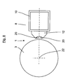
- Fig. 8 shows in a simplified schematic representation of another embodiment of the invention, in which the conductors 20 are formed as Vollmantelleiter. As indicated by a dot and by a cross, the two conductors 20 are traversed in different directions by current to form a conductor loop. In particular, when heating the peripheral surface of the calender roll 3 to lower temperatures, such conductors 20 are sufficient. Also, a protective cover can be omitted. For the rest, the above statements apply accordingly.
Landscapes
- Paper (AREA)
- Casting Or Compression Moulding Of Plastics Or The Like (AREA)
Applications Claiming Priority (1)
| Application Number | Priority Date | Filing Date | Title |
|---|---|---|---|
| DE200810029513 DE102008029513B3 (de) | 2008-06-21 | 2008-06-21 | Heizvorrichtung zum induktiven Erwärmen einer Kalanderwalze |
Publications (3)
| Publication Number | Publication Date |
|---|---|
| EP2135993A2 true EP2135993A2 (fr) | 2009-12-23 |
| EP2135993A3 EP2135993A3 (fr) | 2013-05-29 |
| EP2135993B1 EP2135993B1 (fr) | 2014-03-12 |
Family
ID=40561054
Family Applications (1)
| Application Number | Title | Priority Date | Filing Date |
|---|---|---|---|
| EP20090004425 Not-in-force EP2135993B1 (fr) | 2008-06-21 | 2009-03-27 | Dispositif de chauffage destiné au chauffage inductif d'un rouleau de calandre |
Country Status (2)
| Country | Link |
|---|---|
| EP (1) | EP2135993B1 (fr) |
| DE (1) | DE102008029513B3 (fr) |
Cited By (1)
| Publication number | Priority date | Publication date | Assignee | Title |
|---|---|---|---|---|
| CN116219791A (zh) * | 2023-04-23 | 2023-06-06 | 浙江新亚伦纸业有限公司 | 一种高致密度的纸张压光装置及工艺 |
Families Citing this family (1)
| Publication number | Priority date | Publication date | Assignee | Title |
|---|---|---|---|---|
| DE102019124244A1 (de) * | 2019-09-10 | 2021-03-11 | Andritz Küsters Gmbh | Kalander |
Citations (2)
| Publication number | Priority date | Publication date | Assignee | Title |
|---|---|---|---|---|
| DE3429695C2 (fr) | 1984-08-11 | 1988-09-22 | Kuesters, Eduard, 4150 Krefeld, De | |
| DE102005025997A1 (de) | 2005-06-07 | 2006-12-14 | Voith Patent Gmbh | Kalanderwalzenanordnung |
Family Cites Families (1)
| Publication number | Priority date | Publication date | Assignee | Title |
|---|---|---|---|---|
| KR100508815B1 (ko) * | 2003-01-08 | 2005-08-19 | 국립암센터 | β-카테닌 올리고뉴클레오티드 마이크로칩 및 이를이용하여 β-카테닌 유전자의 돌연변이를 검사하는 방법 |
-
2008
- 2008-06-21 DE DE200810029513 patent/DE102008029513B3/de not_active Expired - Fee Related
-
2009
- 2009-03-27 EP EP20090004425 patent/EP2135993B1/fr not_active Not-in-force
Patent Citations (2)
| Publication number | Priority date | Publication date | Assignee | Title |
|---|---|---|---|---|
| DE3429695C2 (fr) | 1984-08-11 | 1988-09-22 | Kuesters, Eduard, 4150 Krefeld, De | |
| DE102005025997A1 (de) | 2005-06-07 | 2006-12-14 | Voith Patent Gmbh | Kalanderwalzenanordnung |
Cited By (2)
| Publication number | Priority date | Publication date | Assignee | Title |
|---|---|---|---|---|
| CN116219791A (zh) * | 2023-04-23 | 2023-06-06 | 浙江新亚伦纸业有限公司 | 一种高致密度的纸张压光装置及工艺 |
| CN116219791B (zh) * | 2023-04-23 | 2025-03-28 | 上海万卷印刷股份有限公司 | 一种高致密度的纸张压光装置及工艺 |
Also Published As
| Publication number | Publication date |
|---|---|
| DE102008029513B3 (de) | 2009-05-20 |
| EP2135993A3 (fr) | 2013-05-29 |
| EP2135993B1 (fr) | 2014-03-12 |
Similar Documents
| Publication | Publication Date | Title |
|---|---|---|
| DE3920171C2 (fr) | ||
| EP4105006B1 (fr) | Dispositif pour le traitement par pression de matériaux plats | |
| DE3131799A1 (de) | "walzwerk, insbesondere kalander, fuer papier- und andere materialbahnen" | |
| EP0735185B1 (fr) | Calandre pour le traitement des deux surfaces d'une bande de papier | |
| EP2274475B1 (fr) | Cylindre gaufreur chauffé | |
| EP0732445B2 (fr) | Calandre pour le traitement d'une bande de papier | |
| EP2135993B1 (fr) | Dispositif de chauffage destiné au chauffage inductif d'un rouleau de calandre | |
| DE10209544B4 (de) | Verfahren und Vorrichtung zum Erwärmen einer Walze | |
| DE19824542B4 (de) | Walze, Kalander und Verfahren zum Betrieb einer Walze | |
| EP1162045B1 (fr) | Dispositif à rouleau | |
| AT399357B (de) | Kalander zum behandeln einer warenbahn, insbesondere einer papierbahn | |
| EP1314819B1 (fr) | Calandre et procédé pour le lissage de bandes de papier ou carton | |
| WO2004015199A2 (fr) | Dispositif et procede de traitement de surface de bandes de papier et de non-tisses continus similaires a l'aide d'un rouleau pouvant etre chauffe | |
| DE19757474A1 (de) | Papierkalander | |
| DE102007062755B4 (de) | Heizpresse | |
| DE10207371B4 (de) | Vorrichtung zum Bilden eines Langspalts | |
| DE19957795B4 (de) | Heizbare Walze | |
| DE9421548U1 (de) | Walzenmaschine zur Behandlung einer Papierbahn | |
| EP1285990B1 (fr) | Dispositif pour formation d'une presse à ligne de contact élargie | |
| DE202008016510U1 (de) | Bearbeitungsvorrichtung | |
| EP1845191A1 (fr) | Rouleau de calandre pouvant être chauffé | |
| DE202025101590U1 (de) | Vorrichtung für eine Induktionshärteanlage zur Härtung von einer Laufbahn eines Wälzlagers | |
| EP1645685B1 (fr) | Rouleau de calandre et procédé d'entraînement pour un rouleau de calendre | |
| DE102005044100A1 (de) | Beheizbare Kalanderwalze | |
| DE20101859U1 (de) | Beheizbare Walze |
Legal Events
| Date | Code | Title | Description |
|---|---|---|---|
| PUAI | Public reference made under article 153(3) epc to a published international application that has entered the european phase |
Free format text: ORIGINAL CODE: 0009012 |
|
| AK | Designated contracting states |
Kind code of ref document: A2 Designated state(s): AT BE BG CH CY CZ DE DK EE ES FI FR GB GR HR HU IE IS IT LI LT LU LV MC MK MT NL NO PL PT RO SE SI SK TR |
|
| AX | Request for extension of the european patent |
Extension state: AL BA RS |
|
| RIN1 | Information on inventor provided before grant (corrected) |
Inventor name: SVENKA, PETER, DR. Inventor name: JANSEN, BERND Inventor name: DAVYDENKO, EDUARD, DR. |
|
| PUAL | Search report despatched |
Free format text: ORIGINAL CODE: 0009013 |
|
| AK | Designated contracting states |
Kind code of ref document: A3 Designated state(s): AT BE BG CH CY CZ DE DK EE ES FI FR GB GR HR HU IE IS IT LI LT LU LV MC MK MT NL NO PL PT RO SE SI SK TR |
|
| AX | Request for extension of the european patent |
Extension state: AL BA RS |
|
| RIC1 | Information provided on ipc code assigned before grant |
Ipc: D21G 1/02 20060101AFI20130422BHEP |
|
| 17P | Request for examination filed |
Effective date: 20130809 |
|
| GRAP | Despatch of communication of intention to grant a patent |
Free format text: ORIGINAL CODE: EPIDOSNIGR1 |
|
| INTG | Intention to grant announced |
Effective date: 20131009 |
|
| RIN1 | Information on inventor provided before grant (corrected) |
Inventor name: SVENKA, PETER Inventor name: DAVYDENKO, EDUARD Inventor name: JANSEN, BERND |
|
| GRAS | Grant fee paid |
Free format text: ORIGINAL CODE: EPIDOSNIGR3 |
|
| AKX | Designation fees paid |
Designated state(s): DE FI FR IT |
|
| GRAA | (expected) grant |
Free format text: ORIGINAL CODE: 0009210 |
|
| AK | Designated contracting states |
Kind code of ref document: B1 Designated state(s): DE FI FR IT |
|
| REG | Reference to a national code |
Ref country code: DE Ref legal event code: R096 Ref document number: 502009008961 Country of ref document: DE Effective date: 20140424 |
|
| PG25 | Lapsed in a contracting state [announced via postgrant information from national office to epo] |
Ref country code: FI Free format text: LAPSE BECAUSE OF FAILURE TO SUBMIT A TRANSLATION OF THE DESCRIPTION OR TO PAY THE FEE WITHIN THE PRESCRIBED TIME-LIMIT Effective date: 20140312 |
|
| REG | Reference to a national code |
Ref country code: DE Ref legal event code: R097 Ref document number: 502009008961 Country of ref document: DE |
|
| PLBE | No opposition filed within time limit |
Free format text: ORIGINAL CODE: 0009261 |
|
| STAA | Information on the status of an ep patent application or granted ep patent |
Free format text: STATUS: NO OPPOSITION FILED WITHIN TIME LIMIT |
|
| 26N | No opposition filed |
Effective date: 20141215 |
|
| REG | Reference to a national code |
Ref country code: FR Ref legal event code: ST Effective date: 20150210 |
|
| REG | Reference to a national code |
Ref country code: DE Ref legal event code: R097 Ref document number: 502009008961 Country of ref document: DE Effective date: 20141215 |
|
| PG25 | Lapsed in a contracting state [announced via postgrant information from national office to epo] |
Ref country code: IT Free format text: LAPSE BECAUSE OF FAILURE TO SUBMIT A TRANSLATION OF THE DESCRIPTION OR TO PAY THE FEE WITHIN THE PRESCRIBED TIME-LIMIT Effective date: 20140312 |
|
| PG25 | Lapsed in a contracting state [announced via postgrant information from national office to epo] |
Ref country code: FR Free format text: LAPSE BECAUSE OF NON-PAYMENT OF DUE FEES Effective date: 20140512 |
|
| P01 | Opt-out of the competence of the unified patent court (upc) registered |
Effective date: 20230523 |
|
| PGFP | Annual fee paid to national office [announced via postgrant information from national office to epo] |
Ref country code: DE Payment date: 20230526 Year of fee payment: 15 |
|
| REG | Reference to a national code |
Ref country code: DE Ref legal event code: R119 Ref document number: 502009008961 Country of ref document: DE |
|
| PG25 | Lapsed in a contracting state [announced via postgrant information from national office to epo] |
Ref country code: DE Free format text: LAPSE BECAUSE OF NON-PAYMENT OF DUE FEES Effective date: 20241001 |
|
| PG25 | Lapsed in a contracting state [announced via postgrant information from national office to epo] |
Ref country code: DE Free format text: LAPSE BECAUSE OF NON-PAYMENT OF DUE FEES Effective date: 20241001 |