EP2135697A2 - Procédé de fabrication de scies d'entrée - Google Patents
Procédé de fabrication de scies d'entrée Download PDFInfo
- Publication number
- EP2135697A2 EP2135697A2 EP09007874A EP09007874A EP2135697A2 EP 2135697 A2 EP2135697 A2 EP 2135697A2 EP 09007874 A EP09007874 A EP 09007874A EP 09007874 A EP09007874 A EP 09007874A EP 2135697 A2 EP2135697 A2 EP 2135697A2
- Authority
- EP
- European Patent Office
- Prior art keywords
- bending device
- flat material
- round
- die
- circular cylindrical
- Prior art date
- Legal status (The legal status is an assumption and is not a legal conclusion. Google has not performed a legal analysis and makes no representation as to the accuracy of the status listed.)
- Withdrawn
Links
Images


Classifications
-
- B—PERFORMING OPERATIONS; TRANSPORTING
- B23—MACHINE TOOLS; METAL-WORKING NOT OTHERWISE PROVIDED FOR
- B23D—PLANING; SLOTTING; SHEARING; BROACHING; SAWING; FILING; SCRAPING; LIKE OPERATIONS FOR WORKING METAL BY REMOVING MATERIAL, NOT OTHERWISE PROVIDED FOR
- B23D65/00—Making tools for sawing machines or sawing devices for use in cutting any kind of material
-
- B—PERFORMING OPERATIONS; TRANSPORTING
- B21—MECHANICAL METAL-WORKING WITHOUT ESSENTIALLY REMOVING MATERIAL; PUNCHING METAL
- B21D—WORKING OR PROCESSING OF SHEET METAL OR METAL TUBES, RODS OR PROFILES WITHOUT ESSENTIALLY REMOVING MATERIAL; PUNCHING METAL
- B21D11/00—Bending not restricted to forms of material mentioned in only one of groups B21D5/00, B21D7/00, B21D9/00; Bending not provided for in groups B21D5/00 - B21D9/00; Twisting
- B21D11/10—Bending specially adapted to produce specific articles, e.g. leaf springs
-
- B—PERFORMING OPERATIONS; TRANSPORTING
- B21—MECHANICAL METAL-WORKING WITHOUT ESSENTIALLY REMOVING MATERIAL; PUNCHING METAL
- B21D—WORKING OR PROCESSING OF SHEET METAL OR METAL TUBES, RODS OR PROFILES WITHOUT ESSENTIALLY REMOVING MATERIAL; PUNCHING METAL
- B21D5/00—Bending sheet metal along straight lines, e.g. to form simple curves
- B21D5/06—Bending sheet metal along straight lines, e.g. to form simple curves by drawing procedure making use of dies or forming-rollers, e.g. making profiles
- B21D5/10—Bending sheet metal along straight lines, e.g. to form simple curves by drawing procedure making use of dies or forming-rollers, e.g. making profiles for making tubes
-
- B—PERFORMING OPERATIONS; TRANSPORTING
- B21—MECHANICAL METAL-WORKING WITHOUT ESSENTIALLY REMOVING MATERIAL; PUNCHING METAL
- B21D—WORKING OR PROCESSING OF SHEET METAL OR METAL TUBES, RODS OR PROFILES WITHOUT ESSENTIALLY REMOVING MATERIAL; PUNCHING METAL
- B21D5/00—Bending sheet metal along straight lines, e.g. to form simple curves
- B21D5/14—Bending sheet metal along straight lines, e.g. to form simple curves by passing between rollers
Definitions
- the present invention relates to a method according to the preamble of claim 1 and an apparatus for carrying out the method according to the preamble of claim 7 and claim 20, respectively.
- Hole saws with circular cylindrical body are known and are particularly suitable for accurately sawed round holes with large diameters. Such hole saws are usually driven by hand or pillar drilling machines.
- hole saws can be found for example in the construction industry, especially in plumbing or electrician work. Examples of this would be holes for pipe feedthroughs or for plug-in or switch boxes.
- the hole saws are usually subjected to a heat treatment after their production.
- the hole saws are fed in batches to a hardening device and hardened over the entire length including the saw teeth.
- the saw teeth are harder, while the rest of the main body of the respective hole saws remains relatively soft, in order to obtain a favorable for the cutting dynamics microstructure in the material of the hole saw.
- Such saws are referred to in the jargon as "bimetallic saws".
- the hardening device must be designed in such a way that on the one hand there is sufficient space to heat treat the largest possible number of hole saws simultaneously with the hardening device, and on the other hand that the material of each hole saw equally in the respective batch desired properties can be given.
- the ductile flat material with the saw teeth located thereon is hardened to length in a continuous process in the transverse region between the tooth tip line and a connecting line arranged below the tooth root depth before cutting.
- the connecting line may conveniently be the peripheral edge of the strip material facing the saw teeth.
- the essential advantage resulting therefrom is that the space requirement of the hardening device is essentially no longer determined by the layout of the finished hole saw, but rather by the flat material which is in the continuous process.
- the only space that needs to be taken into account for a smooth production implementation is the varying formation of the layer of rolled-up flat material, which is fed from a roll to the respective devices, such as milling, cabinet and now also hardening devices associated with the continuous process are. The space requirement of the hardening device is thus reduced.
- the hardening device is an integral part of a process line, which previously essentially only had a milling and Schränkvortechnisch by which the sheet was moved continuously, but now also includes the hardening device.
- the invention includes a round bending device by which the cut to length and hardened together with the saw teeth thereon hardened flat material, together with the milled thereon in the continuous process, restricted and inventively hardened saw teeth, is permanently formed into the circular cylindrical body.
- the flat material is given the necessary material properties even before the forming process, which are advantageous in view of the cutting dynamics of the hole saw formed therefrom.
- Another significant advantage is that diameter changes of the hole saw due to hardening distortion, the hardening of a fully formed hole saw in particular due to different cooling rates can occur, are avoidable because the flat material is formed accurately after the hardening of the tape with the saw teeth.
- hole saws can be produced with which far more accurate diameters can be cut than in conventional hole saws.
- the flat material is made of a metallic material.
- Metallic materials provide the necessary conditions to give the said tool advantageous cutting properties and are weldable. Therefore, it is proposed that the transverse edges of the flat material are welded together along their entire contact zone in order to be able to transfer the occurring cutting forces in the circular cylindrical base body of the hole saw safely.
- the circular cylindrical base body is connected at its upper side with a corresponding circular cover.
- the hole saw receives its typical stiffness.
- a center drill is mounted in the center of the lid or a bayonet lock device or the like.
- the lid consists of metallic flat material, which is welded to the circular cylindrical base body.
- the weld with which the cover and the flat material are connected a circumferential annular seam, so that the torque generated by the hand drill or drill press or similar drive means can be transmitted securely into the circular cylindrical body of the hole saw.
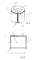
- FIGS. 2 and 3 show a hole saw 1 with a circular cylindrical body 2, which is formed from a ductile sheet 3.
- the flat material 3 is self-hardened and furthermore has saw teeth 4 hardened by heat treatment, so that the hole saw 1 can reliably cut.
- the flat material 3 is hardened with the saw teeth 4 located thereon before cutting to length in the continuous process in the transverse region between the tooth tip line 5 and below the Zahnfusstiefe connecting line 6 and was cut to length after curing for the forming process.
- FIGS. 1 and 4a show a round bending device 7 with the fabric produced and cut in the flow process according to the invention flat material 3 is permanently formed with the hardened saw teeth 4 thereon to the circular cylindrical base body 2.
- a bending part hardened in a continuous process namely the flat material 3
- a bending part hardened in a continuous process namely the flat material 3
- a bending part hardened in a continuous process namely the flat material 3
- a cutting tool 7 which has a very favorable microstructure course in terms of cutting dynamics in the circular saw blade.
- a round bending device 7 in which the cut to length flat material 3 in its longitudinal direction on a transverse jacket area 11 of the circular bending device 7 associated forming circular cylindrical die 12 can be applied.
- the flat material 3 thus applied can be clamped in this position with a counter-punch 13 which is associated with the die 12 and acts on the flat material 3 from the outside.
- a plurality of bending punches 14 are provided, which can be moved up from respectively different positions with a contour 15 corresponding to the die 12 and complementary to the circular cylindrical shape of the die 12, against the free ends 16 of the clamped flat material 3.
- the bending punches 14 can be moved from the outside to the flat material 3 in such a way that from the flat material 3 a round body 17 is formed stepwise around the die 12, the inside diameter of which corresponds to the outside diameter 18 of the die 12.
- FIG. 1 a preferably central contact position of the flat material 3 is shown on the cladding region 11, so that the bending punches 14 can each be brought to the free ends 16 of the flat material 3 in the same way.
- the bending punch 14 with the contour 15 in the maximum extension position can be moved up to a distance to the die 12, which corresponds to the thickness of the sheet 3.
- the outer diameter 18 of the female die 12 correspond to the inner diameter 19 of the circular-cylindrical main body 2.
- FIG. 1 shows a preferred embodiment of the round bending device 7, in which the counter-punch 13 and the punch 14 are die-bending punch.
- the respective die shapes of the punches 13, 14 are partial circle recesses 20, which correspond to the outer diameter 18 of the circular cylindrical die 12 complementary.
- the achievable advantage of this structural solution lies in the fact that the flat material 3 is clamped and pre-bent by the counter-holding punch 13 and, secondly, that the flat material 3 is first pre-bent by the pitch circle recesses 20 and then dimensioned according to the outside diameter 18 on the die wall.
- the pitch circle 20 of the counter-punch 13 is semicircular.
- the preferably centrally applied and cut flat material 3 is pre-bent by this design measure U-shaped.
- this creates a total of a die, which forms a circle concentric with the die 12 in the maximum bending position of the respective dies 13, 14, which corresponds in diameter to the outer diameter 18 of the circular-cylindrical basic body 2. This is especially true in the Fig. 1 shown top view.
- the bending punches 14 arranged in the transverse direction can be moved back again once their maximum bending position has been reached so that a bending punch 14 disposed opposite the counter-holding punch 13 in pairs will round the round 17, its pitch circle recess 20 being semicircular.
- the round 17 to be formed in the die is pressed in a comprehensive manner, so that the shape of the sheet 3 is largely adapted to the circular die shape. A springback of the transverse edges 8 of the round 17 is thereby reduced.
- a controllable heating device be associated with the round bending device 7, which brings the flat material 3 to a predetermined temperature and maintains this temperature.
- the advantage here is that the sheet material hardened in the continuous process and cut to length 3 is pliable moldable in the die.
- the flat material 3 during the forming process red-hot below the tempering temperature of the saw teeth 4 is tempered, so that the hardness of the saw teeth is not adversely affected.
- the tempering temperature of the saw teeth 4 650 ° C.
- the round body 17 can be shaped with a calibratable diameter which corresponds at most to the amount of a predetermined threshold value.
- circular bending device 7 would this purpose several matrices 12 with mutually different diameters 18 conceivable, to each of which complementary corresponding swaging forms are provided. For this purpose, it would further be conceivable that these matrices 12 with their associated die shapes can be reversibly exchangeably attached to the round bending device 7.
- the threshold here is 50 mm.
- Fig. 1 shown round bending device 7 from the sheet 3, a round 17 formed, in which the transverse edges 8 are resiliently open.
- the round 17 assumes the outer diameter of this body as an inner diameter 19 as soon as its transverse edges 8 are pressed towards each other.
- round bender 7 meets this requirement as a circular cylindrical body, it is preferably proposed that the round 17 is held by means of a round bending device 7 associated holding device to size.
- transverse edges 8 of the flat material 3 are held dull against each other after the forming process and joined together.
- the circular cylindrical body 2 is replaced by a permanent and dimensionally accurate shape.
- the material of the sheet 3 is preferably metallic.
- the lid 9 is made of metallic sheet 3 and is welded to the circular-cylindrical base body 2.
- FIG. 3 shows a fillet weld 10, which preferably connects in a circumferential manner the lid 9 with the circular cylindrical body 2.
- the cover which can serve for example for fastening the hole saw 1 to a hand or drill press, or the hole in the center of the lid for receiving a center drill.
- bayonet closure-typical grooves are arranged at the upper end of the hole saw 1 in order to secure the hole saw 1 in the cutting direction to a closure device suitable for this purpose.
- a preferred circular bending device 7 is shown.
- the round bending device 7 here is a roll bending machine 23 with a driven, mounted in stationary bearings main roll 24. To the main roll 24 is cut to length and according to the invention hardened sheet 3 is bent into a round 17 with kalibrierbarem diameter, which is particularly in 4b is pictured.
- the main roller 24 is associated with an adjustable counter-roller 25, which is also driven.
- two bending rolls 26, 27 are provided, one of which lie on the inlet side 28 and the other on the outlet side 29 of the roller pair formed by the two rollers 24, 25.
- the bending rollers 26, 27 are guided and mounted in plain bearing devices.
- the roll round bending machine 23 can be equipped with rollers of different dimensions, the calibrated diameter preferably being above a predetermined threshold value.
- the threshold here is preferably 40 mm
- Fig.2 shows a hole saw 1, the circular cylindrical body 2 is formed by a processed according to the invention in a continuous sheet 3.
- the transverse edges 8 of the sheet 3 are materially connected. It is essential here that the hole saw 1 produced according to the invention now readily withstands the occurring stresses during sawing, without the need for additional heat treatment. The entire cycle time of the tool produced by the method according to the invention is reduced and the productivity of the entire manufacturing process is thus increased, in particular parking space of external hardening devices is saved or otherwise made usable. The size of the hardening device is now limited to the formation of the flat material 3 in the continuous process, which layer is supplied to the position of the roll of the device.
- hole saws 1 according to the invention cut holes with higher accuracy than hole saws, which have been produced by known methods.
Landscapes
- Engineering & Computer Science (AREA)
- Mechanical Engineering (AREA)
- Bending Of Plates, Rods, And Pipes (AREA)
- Heat Treatment Of Articles (AREA)
Applications Claiming Priority (1)
| Application Number | Priority Date | Filing Date | Title |
|---|---|---|---|
| DE102008029249A DE102008029249A1 (de) | 2008-06-19 | 2008-06-19 | Verfahren zur Herstellung von Lochsägen |
Publications (2)
| Publication Number | Publication Date |
|---|---|
| EP2135697A2 true EP2135697A2 (fr) | 2009-12-23 |
| EP2135697A3 EP2135697A3 (fr) | 2014-12-03 |
Family
ID=41061245
Family Applications (1)
| Application Number | Title | Priority Date | Filing Date |
|---|---|---|---|
| EP09007874.2A Withdrawn EP2135697A3 (fr) | 2008-06-19 | 2009-06-16 | Procédé de fabrication de scies d'entrée |
Country Status (2)
| Country | Link |
|---|---|
| EP (1) | EP2135697A3 (fr) |
| DE (1) | DE102008029249A1 (fr) |
Cited By (1)
| Publication number | Priority date | Publication date | Assignee | Title |
|---|---|---|---|---|
| CN108672526A (zh) * | 2018-05-28 | 2018-10-19 | 北京清新环境技术股份有限公司天津分公司 | 一种卷板设备及自动化卷板工艺 |
Family Cites Families (4)
| Publication number | Priority date | Publication date | Assignee | Title |
|---|---|---|---|---|
| US2995171A (en) * | 1955-12-14 | 1961-08-08 | Hausler Christian | Machine for bending metal plates |
| JPS5031111B1 (fr) * | 1968-12-21 | 1975-10-07 | ||
| CH554716A (fr) * | 1972-04-24 | 1974-10-15 | Retmeca Sa | Procede de fabrication par formage de profiles tubulaires, machine pour la mise en oeuvre du procede et profile ainsi obtenu. |
| US6939092B2 (en) * | 2003-06-18 | 2005-09-06 | Irwin Industrial Tool Company | Sheet metal hole cutter |
-
2008
- 2008-06-19 DE DE102008029249A patent/DE102008029249A1/de not_active Withdrawn
-
2009
- 2009-06-16 EP EP09007874.2A patent/EP2135697A3/fr not_active Withdrawn
Cited By (1)
| Publication number | Priority date | Publication date | Assignee | Title |
|---|---|---|---|---|
| CN108672526A (zh) * | 2018-05-28 | 2018-10-19 | 北京清新环境技术股份有限公司天津分公司 | 一种卷板设备及自动化卷板工艺 |
Also Published As
| Publication number | Publication date |
|---|---|
| EP2135697A3 (fr) | 2014-12-03 |
| DE102008029249A1 (de) | 2009-12-31 |
Similar Documents
| Publication | Publication Date | Title |
|---|---|---|
| DE10041280C2 (de) | Verfahren und Vorrichtung zum flexiblen Walzen eines Metallbandes | |
| EP2802425B1 (fr) | Dispositif et procede d'emboutissage d'elements en forme de coque avec decoupe du fond et de la paroi integree | |
| EP2781280B1 (fr) | Procédé de fabrication d'une liaison rivetée refoulée avec un mouvement pendulaire rotatif | |
| EP2529849A2 (fr) | Dispositif et procédé de fabrication de tuyaux fendus à partir de plaques de tôle | |
| EP2484462B1 (fr) | Procédé de production d'une préforme forgée et dispositif de déformage ou dispositif de refoulment chaud | |
| DE1940341B2 (de) | Verfahren und Einrichtung zum Herstellen von Metalleisten, insbesondere von rohrförmigen Schweißelektroden, aus einem Stabmaterial | |
| EP3820631B1 (fr) | Presse à former à jco à réglage élargi | |
| DE10119839C2 (de) | Verfahren zur Herstellung eines Achselements für Kraftfahrzeuge | |
| DE1948805A1 (de) | Verfahren und Vorrichtung zum Herstellen ringfoermiger Rohteile fuer Zahnkraenze und andere ringfoermige Bauteile | |
| DE102011102288B4 (de) | Vorrichtung und Verfahren zur Herstellung eines Stirnrads mit einer Schrägverzahnung | |
| EP3221068B1 (fr) | Procédé de fabrication d'un élément moulé à symétrie de révolution | |
| DE102008002736A1 (de) | Vorrichtung zur Bearbeitung einer Platte zu einem nanostrukturierten Formteil und ein Verfahren zur Herstellung desselben | |
| EP2832868B1 (fr) | Outil de presse, ainsi que procédé de fabrication d'un outil de presse | |
| EP2839900B1 (fr) | Procédé et dispositif de fabrication d'une section de raccordement pourvue d'une face terminale comme élément d'un outil | |
| EP2135697A2 (fr) | Procédé de fabrication de scies d'entrée | |
| DE102007037784B4 (de) | Verzahnungsbauteil zur Übertragung von Antriebskräften | |
| DE1602446A1 (de) | Herstellungsverfahren fuer laufringe | |
| DE3101123A1 (de) | Verfahren und einrichtung zum verformen eines metallstabes in ein tulpenfoermiges teil durch fliesspressen in einer geschlossenen kammer | |
| DE10121546A1 (de) | Verfahren und Drückrolle zum Anformen einer Nabe | |
| EP0244648A1 (fr) | Procédé et appareil de fabrication de roues dentées | |
| DE1075082B (de) | Vorrichtung zur Verformung der inneren Oberfläche eines rohrförmigen Werkstückes | |
| DE2740981A1 (de) | Stanzmesser | |
| DE2735868A1 (de) | Verfahren und vorrichtung zur herstellung von starkwandigen hohlkoerpern aus aluminium oder aluminiumlegierungen durch warmfliesspressen | |
| EP2314397B1 (fr) | Procédé de fabrication d'un élément à partir d'une tôle | |
| EP3720627B1 (fr) | Procédé de fabrication d'un élément d'assemblage |
Legal Events
| Date | Code | Title | Description |
|---|---|---|---|
| PUAI | Public reference made under article 153(3) epc to a published international application that has entered the european phase |
Free format text: ORIGINAL CODE: 0009012 |
|
| AK | Designated contracting states |
Kind code of ref document: A2 Designated state(s): AT BE BG CH CY CZ DE DK EE ES FI FR GB GR HR HU IE IS IT LI LT LU LV MC MK MT NL NO PL PT RO SE SI SK TR |
|
| PUAL | Search report despatched |
Free format text: ORIGINAL CODE: 0009013 |
|
| AK | Designated contracting states |
Kind code of ref document: A3 Designated state(s): AT BE BG CH CY CZ DE DK EE ES FI FR GB GR HR HU IE IS IT LI LT LU LV MC MK MT NL NO PL PT RO SE SI SK TR |
|
| AX | Request for extension of the european patent |
Extension state: AL BA RS |
|
| RIC1 | Information provided on ipc code assigned before grant |
Ipc: B23D 65/00 20060101AFI20141028BHEP Ipc: B23B 51/04 20060101ALI20141028BHEP Ipc: B28D 1/04 20060101ALI20141028BHEP |
|
| 17P | Request for examination filed |
Effective date: 20141211 |
|
| RBV | Designated contracting states (corrected) |
Designated state(s): AT BE BG CH CY CZ DE DK EE ES FI FR GB GR HR HU IE IS IT LI LT LU LV MC MK MT NL NO PL PT RO SE SI SK TR |
|
| STAA | Information on the status of an ep patent application or granted ep patent |
Free format text: STATUS: THE APPLICATION HAS BEEN WITHDRAWN |
|
| 18W | Application withdrawn |
Effective date: 20160610 |