EP2135662B2 - Elément filtrant compressible avec des capuchons d'extrémité inclinés les uns vers les autres - Google Patents
Elément filtrant compressible avec des capuchons d'extrémité inclinés les uns vers les autres Download PDFInfo
- Publication number
- EP2135662B2 EP2135662B2 EP09006067A EP09006067A EP2135662B2 EP 2135662 B2 EP2135662 B2 EP 2135662B2 EP 09006067 A EP09006067 A EP 09006067A EP 09006067 A EP09006067 A EP 09006067A EP 2135662 B2 EP2135662 B2 EP 2135662B2
- Authority
- EP
- European Patent Office
- Prior art keywords
- filter element
- filter medium
- components
- element according
- filter
- Prior art date
- Legal status (The legal status is an assumption and is not a legal conclusion. Google has not performed a legal analysis and makes no representation as to the accuracy of the status listed.)
- Active
Links
Images

Classifications
-
- B—PERFORMING OPERATIONS; TRANSPORTING
- B01—PHYSICAL OR CHEMICAL PROCESSES OR APPARATUS IN GENERAL
- B01D—SEPARATION
- B01D46/00—Filters or filtering processes specially modified for separating dispersed particles from gases or vapours
- B01D46/52—Particle separators, e.g. dust precipitators, using filters embodying folded corrugated or wound sheet material
- B01D46/521—Particle separators, e.g. dust precipitators, using filters embodying folded corrugated or wound sheet material using folded, pleated material
-
- B—PERFORMING OPERATIONS; TRANSPORTING
- B01—PHYSICAL OR CHEMICAL PROCESSES OR APPARATUS IN GENERAL
- B01D—SEPARATION
- B01D39/00—Filtering material for liquid or gaseous fluids
-
- B—PERFORMING OPERATIONS; TRANSPORTING
- B01—PHYSICAL OR CHEMICAL PROCESSES OR APPARATUS IN GENERAL
- B01D—SEPARATION
- B01D53/00—Separation of gases or vapours; Recovering vapours of volatile solvents from gases; Chemical or biological purification of waste gases, e.g. engine exhaust gases, smoke, fumes, flue gases, aerosols
- B01D53/34—Chemical or biological purification of waste gases
- B01D53/92—Chemical or biological purification of waste gases of engine exhaust gases
-
- B—PERFORMING OPERATIONS; TRANSPORTING
- B60—VEHICLES IN GENERAL
- B60H—ARRANGEMENTS OF HEATING, COOLING, VENTILATING OR OTHER AIR-TREATING DEVICES SPECIALLY ADAPTED FOR PASSENGER OR GOODS SPACES OF VEHICLES
- B60H3/00—Other air-treating devices
- B60H3/06—Filtering
-
- B—PERFORMING OPERATIONS; TRANSPORTING
- B01—PHYSICAL OR CHEMICAL PROCESSES OR APPARATUS IN GENERAL
- B01D—SEPARATION
- B01D2275/00—Filter media structures for filters specially adapted for separating dispersed particles from gases or vapours
- B01D2275/20—Shape of filtering material
- B01D2275/203—Shapes flexible in their geometry, e.g. bendable, adjustable to a certain size
-
- B—PERFORMING OPERATIONS; TRANSPORTING
- B01—PHYSICAL OR CHEMICAL PROCESSES OR APPARATUS IN GENERAL
- B01D—SEPARATION
- B01D2275/00—Filter media structures for filters specially adapted for separating dispersed particles from gases or vapours
- B01D2275/20—Shape of filtering material
- B01D2275/206—Special forms, e.g. adapted to a certain housing
-
- Y—GENERAL TAGGING OF NEW TECHNOLOGICAL DEVELOPMENTS; GENERAL TAGGING OF CROSS-SECTIONAL TECHNOLOGIES SPANNING OVER SEVERAL SECTIONS OF THE IPC; TECHNICAL SUBJECTS COVERED BY FORMER USPC CROSS-REFERENCE ART COLLECTIONS [XRACs] AND DIGESTS
- Y10—TECHNICAL SUBJECTS COVERED BY FORMER USPC
- Y10S—TECHNICAL SUBJECTS COVERED BY FORMER USPC CROSS-REFERENCE ART COLLECTIONS [XRACs] AND DIGESTS
- Y10S55/00—Gas separation
- Y10S55/28—Carburetor attached
Definitions
- the invention relates to a filter element according to the preamble of patent claim 1.
- the EP 1 867 378 A1 shows such a filter element with mutually parallel end caps.
- the DE 10 2004 054 274 A1 discloses housings which are telescopically collapsible, and more particularly to a filter element housed in a two-part housing. From the FR 798 869 A For example, a chamber is known which receives an absorbent substance and has a conically shaped base.
- the WO 2005/115 581 A1 shows a cylindrical filter element with an elliptical flange inclined to a first end cap and projecting from the filter element, to which a seal is assigned. From the DE 20 2005 003 046 U1 a filter element is known in which the filter medium is interrupted by a gas-carrying nozzle.
- Filter elements of the type mentioned are already known from the prior art and find particular in the Motorzuluftfiltration in motor vehicles, namely in their intake systems, application.
- the known filter elements are equipped as filter cartridges, in particular as a round filter.
- a filter medium is sandwiched between two mutually parallel end caps.
- an axially arranged flow channel is formed, which can be connected to an intake system.
- the fluid flow which passes through the wall surface, namely, is sucked through to the motor, is guided through the end cap-side flow channel.
- the invention is therefore the object of a filter element of the type mentioned in such a way and further, that this can be used in tight spaces.
- the aforementioned filter element is characterized in that the components are inclined to each other or have mutually inclined surfaces, wherein the components define two mutually inclined planes of the filter medium and wherein the filter medium has different heights h at different locations.
- two components which are arranged inclined to each other or have surfaces that are inclined to each other, allow an arrangement of the filter element in tight Baurämen.
- the components are inventively formed as the filter medium on both sides covering and receiving end caps.
- the inclined arrangement of the components leads to a bevel of the filter element, so that it can be arranged in narrow inclined spaces.
- the components define two mutually inclined planes of the filter medium. It is advantageous that a beveled substantially cylindrical filter medium can be glued with inclined base surfaces in the components or molded around by these. In a folded filter medium, the wrinkle-stitched sides may lie in the inclined planes and the pleat-backs may extend substantially orthogonal to a component.
- the filter medium has different heights h at different locations. Due to this specific embodiment, it is possible to position a filter element between two components, wherein a flow channel is formed in a component.
- the flow channel can be arranged where the filter medium has a low height.
- the components are inclined or have inclined surfaces in such a way that the filter element shows a wedge shape. Due to this specific embodiment, the filter element can be inserted to save space in sloping spaces. Furthermore, the wedge shape allows the formation of a high wall surface and a low wall surface, wherein the high wall surface opposite to the flow channel and thereby can be effectively acted upon with fluid to be filtered.
- a wedge-shaped filter element with a laterally arranged flow channel can be installed particularly well in tight spaces, since the height of the filter element is reduced in the region of the formation of the flow channel. Furthermore, a wedge-shaped filter element has two mutually inclined planes and can thereby be compressed upon application of force to the planes
- the filter element could have at least one laterally arranged flow channel to the through-flow volume.
- a laterally arranged flow channel whose axis is oriented substantially orthogonal to the wall surface of the filter medium, allows use of the filter element in tight spaces.
- a laterally arranged flow channel allows a fluid sucked into the flow-through volume to flow out in the plane of the filter medium.
- the flow channel could face a region of the wall surface facing away from it.
- a fluid can be effectively sucked through the filter medium and filtered by this.
- the suction carried by the flow channel is directed directly onto the wall surface.
- the flow channel could be formed out of a component and formed integrally therewith.
- the filter element of three components namely first and second component and filter medium can be manufactured.
- recesses are formed in the filter medium itself, which can pass through a flow channel.
- the flow channel could be oriented parallel to the surface of a component. This concrete embodiment ensures a very favorable flow guidance of the incoming fluid, since the fluid can flow along the surface of the component in a laminar manner.
- the known filter cartridges are currently often arranged in crumple zones and thus crash-relevant areas of a motor vehicle. This is problematic that the known filter cartridges offer a very large resistance to deformation due to their compact design and rigid shape and limit the deformability of the entire intake system. This is particularly critical when a road user, e.g. a pedestrian, with a body part abuts against a region of the body, under which such a hard component is arranged.
- a filter element made of paper is arranged under the bodywork, for example the hood, in an intake system. Then the deformability of the intake system and thus the body through the filter element is so severely limited that a significant risk of injury to the road user is given.
- the known filter elements must be arranged so spaced from body components, that a trouble-free deformability of the body or the intake system is ensured. The consequence of this are unused space, especially under the hood.
- the filter medium is made of a nonwoven fabric and folded such that a distance between the components in their application of force is at least partially reversibly reduced.
- a reversibly deformable filter element is produced, which offers a sufficiently large filter surface.
- the filter performance of a paper can also be ensured by a nonwoven fabric which has a certain fold at a lower fold density.
- the fold backs of two adjacent folds can be spaced further apart than those of a filter medium made of paper. So it can be reduced the fold density.
- the further spacing of the folds allows buckling of the folds and thus a problem-free reduction of the distance between the components.
- a nonwoven fabric has a particular elasticity, which allows a reversible deformation of the filter element. This ensures a conditional serviceability of the filter element after deformation by an accident, namely a so-called emergency running property.
- the distance between the components could be reduced by at least 20%, preferably by at least 75%.
- This specific embodiment ensures that a pedestrian who comes with a body part against the body of a motor vehicle, is largely spared injury. The risk of contracting is thereby considerably reduced.
- the filter medium has heights h which can be reduced by at least 20%, preferably by at least 75%.
- the components can be made of a hard material and must contribute almost nothing to the compressibility of the entire filter element.
- a particularly cost-effective manufacturing process can be realized, since the components can be manufactured from conventional plastics.
- the components are made of a consolidated nonwoven fabric. As a result, a material-uniform structure of the filter element can be realized.
- the compressibility of the filter element could be adjusted by modifying the nonwoven fabric used. This modification could be realized by using fibers of different bending stiffness. In this case, synthetic fibers could be combined with natural fibers in a certain mixing ratio.
- the stiffness of the nonwoven fabric could also be adjusted by different manufacturing methods. For example, by suitable choice of the parameters of a water jet needling, the stiffness of the nonwoven fabric could be adjusted.
- the nonwoven fabric could comprise synthetic fibers or consist entirely of synthetic fibers. It is conceivable that the synthetic fibers are made of polypropylene, polyester or polybutadiene terephthalate. Some motor vehicle manufacturers require from a useable filter element in intake systems according to DIN ISO 5011 a very specific filter performance, namely a separation efficiency of more than 98%. According to this standard, a filter element only shows sufficient filter performance if 98% of the test dusts in the air to be filtered are separated in the filter medium. Surprisingly, it has been found that a nonwoven fabric comprising synthetic fibers meets these requirements with problem-free deformability. The easy deformability is essentially realized by a relatively wide pleat spacing.
- the filter medium could be made of a thermoplastic nonwoven fabric.
- a thermoplastic nonwoven surprisingly shows a high compressibility in the folded state. Tests have shown that a folded 48 mm high nonwoven fabric, which is urged in the direction of the pleats, is compressible by 28.32 mm at 100 N. At 0, 5 N, 10 N, 20 N and 50 N, the examined nonwoven fabric can be reduced in height by 0, 0.4 mm, 2.76 mm, 9.54 mm and 17.23 mm respectively. The force vector is oriented parallel to the fold backs in this measurement.
- the application of force takes place on a nonwoven fabric surface of 40 mm width and 100 mm length.
- the thermoplastic nonwoven fabric used is a nonwoven fabric which is made of polyester fibers.
- the nonwoven fabric has no binder, but the fibers are welded together by thermal consolidation processes.
- the nonwoven fabric has a basis weight of 230 g / m 2 .
- Nonwovens which have a basis weight of 100 to 500 g / m 2 .
- Nonwovens of this basis weights have a sufficiently high inherent rigidity in order to space two components apart and at the same time provide a sufficiently high filtration capacity.
- nonwoven fabric surprisingly allows the spacing of the components solely by the filter medium, since the nonwoven fabric exhibits a sufficiently high inherent stiffness due to its fiber structure.
- a nonwoven fabric has a very high tensile strength and thus high stability, even after soaking and subsequent drying in contrast to paper.
- a nonwoven fabric made of synthetic material shows a high temperature stability and is therefore suitable for use in engine compartments of motor vehicles.
- Other stabilizers, which supported the filter medium in the spacing of the components are not absolutely necessary. As a result, a cost-effective production of the filter element can be realized.
- further stabilizing agents can be provided in order to set the deformability of the filter element in a defined manner.
- the filter medium could have folds whose wrinkle faces face the components.
- This specific embodiment allows a problem-free connection of the filter medium with the components.
- an adhesive is assigned to the components, in which the Faltenstimfact immerse and thus enter into a composite with the components.
- the fold backs of two adjacent folds are 0.5 to 3 cm apart.
- the selection of the distance from this range has proved to be particularly advantageous in order to provide both a problem-free deformability of the filter medium and on the other hand still a sufficiently large effective filter area, which is necessary for the Motorzuluftfiltration.
- Paper filter media can not provide adequate filter performance at such a pleat back spacing. no deposition rate required by the automotive industry, and are therefore unsuitable for intake systems.
- the folds are provided with predetermined bending points, which cause a defined buckling of the filter medium when force is applied.
- the wrinkles are imprinted contours that specify or initiate a specific buckling behavior of the folds upon application of force to the components.
- the predetermined bending points could be impressed on the filter medium by ultrasonic welding processes. Ultrasonic welding processes can be carried out particularly quickly and cost-effectively, and allow a problem-free regional rejuvenation of a filter medium. It is also conceivable to realize an embossing of the filter medium solely by application of force.
- the pleat backs could include an angle different from 90 ° with the base surfaces of the components.
- the thus inclined pleat backs can then be easily and particularly easily deformed such that the components approach each other.
- At least one component could be made of a material that is harder or more rigid than the filter medium.
- This specific embodiment allows a production of a stable filter element, which protects the filter medium against impact and shock. Furthermore, the filter medium is protected against contamination. Against this background, it is conceivable that at least one component is made of a consolidated nonwoven fabric.
- At least one component could be produced by injection molding. It is conceivable that the components are made of polypropylene or polyamide.
- At least one component could be made foamed.
- a component is a very good composite with the filter medium, since the foamed material can flow around the folds of the filter medium.
- Polyurethane could be used as the foamed material. This material is easy to process.
- Metals give the filter element high stability and temperature resistance.
- At least one component could be assigned predetermined breaking means, which space apart the components in addition to the filter medium.
- the predetermined breaking means could be designed such that they break with a very specific application of force to the components and ensure a deformability of the filter element.
- the stabilizing elements are arranged between the components. As a result, a compression and rebound of the components is possible.
- the stabilizing elements could be designed as spiral springs or leaf springs, since these are mechanically very stable and easily adjustable with regard to their spring constants.
- the filter element could be designed as an air filter of a motor vehicle.
- the easy deformability of the filter element according to the invention makes it ideal for the arrangement in a motor vehicle directly under the hood, where usually air filters are positioned.
- a component acts as a cover of the volume in the air filter housing into which the filter element is inserted.
- the component could be assigned at the factory to seal the volume in the air filter housing seals. As a result, a faster assembly process can be realized.
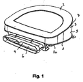
- Fig. 1 1 shows a filter element comprising a first component 1, a second component 2 and a filter medium 3 arranged between the components 1, 2, the components 1, 2 being spaced apart by the fluid medium 3.
- the components 1, 2 and the filter medium 3 define a volume 4 which can be flowed through, wherein the filter medium 3 forms a peripheral wall surface 5, through which a fluid can pass for filtering.
- the filter element has a laterally arranged flow channel 6 to the volume 4 through which it can flow.
- the flow channel 6 is laterally, namely laterally oriented and thereby substantially orthogonal to the wall surface 5 of the filter medium 3.
- the flow channel 6 is opposite to a region 7 facing away from the wall surface 5.
- the components 1, 2 receive the filter medium 3.
- the flow channel 1 is formed from a component 1 and integrally formed therewith.
- the flow channel 6 is oriented parallel to the surface 8 of a component.
- the components 1, 2 are oriented inclined to one another.
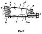
- Fig. 2 shows a sectional view of the filter element according to Fig. 1 ,
- the filter element comprises a first component 1, a second component 2 and a filter medium 3 arranged between the components 1, 2, the components 1, 2 being spaced apart by the filter medium 3.
- the components 1, 2 and the filter medium 3 define a flow-through volume 4, wherein the filter medium forms a wall surface 5, through which a fluid can pass for filtering.
- the filter element has a laterally arranged flow channel 6 to the volume 4 through which it can flow.
- the flow channel 6 is opposite to a region 7 facing away from the wall surface 5. In this case, the flow channel 6 is formed out of the component 1 and integrally formed therewith.
- the flow channel 6 is oriented parallel to the surface 8 of the component 1.
- the components 1, 2 are inclined to each other and give the filter element a wedge shape.
- the filter medium in the Fig. 1 to 4 described filter elements is made of a nonwoven fabric and folded such that a distance between the components 1, 2 in the application of force is at least partially reversibly reduced.
- the distance can be reduced by at least 20%, preferably by at least 75%.
- the filter medium 3 has heights h which are at least 20%, preferably at least 75% are reducible. Fig. 2 it can be seen that the filter medium 3 has different heights h at different locations. In the region of the flow channel 6, the filter medium 3 has a lower height than on the side facing away from the flow channel 6.
- the filter medium 3 is made of a nonwoven fabric comprising synthetic fibers or various fibers of different bending stiffness.
- the filter medium 3 is made of a thermoplastic nonwoven fabric.
- Fig. 3 shows in a schematic sectional view of the filter element according to Fig. 1 partly the folds 10 of the filter medium 3.
- the fold backs 9 of two adjacent folds 10 have a spacing of 0.5 to 3 cm.
- Fig. 3 schematically shows that at least one component 1, 2 elastic stabilizing elements 13 are assigned.
- the stabilizing element 13 in Fig. 3 is designed as a spring, which counteracts a compression of the components 1, 2.
- Fig. 4 shows in a schematic plan view of a rectangular shaped filter element, the Faltenstimcondition 11, facing a perforated component 2 facing and glued thereto or encapsulated by this.
- Two or more folds 10 are interconnected at defined intervals such that the fold walls or fold flanks 10a are at least partially adjacent to one another.
- At least one component 1, 2 could be assigned predetermined breaking means 12, the in Fig. 4 are shown by a dashed line.
- the predetermined breaking means 12 could be formed by a material weakening in the component 2.
- At least one component 1, 2 of the in the Fig. 1 to 4 described filter elements could be made of a material that is harder than the filter medium 3.
- at least one component 1, 2 could be produced by injection molding.
- the components 1, 2 in the Fig. 1 to 4 define two mutually inclined planes 14a and 14b of the filter medium 3.
- a beveled substantially cylindrical filter medium 3 with inclined base surfaces, namely the planes 14a and 14b is glued into the components 1, 2 or encapsulated by these.
- the pleat faces 11 lie in the inclined planes 14a and 14b, and the pleat backs 9 extend substantially orthogonally or nearly orthogonal to a face of the component 1.
- the pleat backs 9 subtend an acute angle with a face of the member 1.
- the component 2 in Fig. 2 is formed substantially flat, the component 1 in Fig. 2 has a flat surface 8 on which a ring 8a is formed inclined.
- the flat surface 8 extends substantially across the width of the flow channel 6.
- the collar 8a is arranged to receive the slanted filter medium 3. *** "
- the pleats 9 form in Fig. 2 with the rim 8a a right angle and close with the surface 8 an acute angle.
- the pleat backs 9 also close with the component 2 an acute angle.
Landscapes
- Chemical & Material Sciences (AREA)
- Chemical Kinetics & Catalysis (AREA)
- Engineering & Computer Science (AREA)
- Combustion & Propulsion (AREA)
- Health & Medical Sciences (AREA)
- Biomedical Technology (AREA)
- Environmental & Geological Engineering (AREA)
- Analytical Chemistry (AREA)
- General Chemical & Material Sciences (AREA)
- Oil, Petroleum & Natural Gas (AREA)
- Mechanical Engineering (AREA)
- Filtering Materials (AREA)
- Filtering Of Dispersed Particles In Gases (AREA)
- Lubrication Details And Ventilation Of Internal Combustion Engines (AREA)
Claims (16)
- Elément filtrant comprenant un premier composant (1), un deuxième composant (2) et un milieu filtrant (3) disposé entre les composants (1, 2), les composants (1, 2) étant espacés l'un de l'autre par le milieu filtrant (3), les composants (1, 2) et le milieu filtrant (3) limitant un volume (4) pouvant être parcouru par un écoulement, le milieu filtrant (3) constituant une surface de paroi (5), à travers laquelle un fluide peut passer en vue de sa filtration, les composants (1, 2) étant réalisés sous forme de capuchons d'extrémité recouvrant des deux côtés et recevant le milieu filtrant (3), le milieu filtrant (3) étant fabriqué en une étoffe non tissée et étant plié de telle sorte qu'une distance entre les composants (1, 2) puisse être réduite de manière réversible au moins en partie lors de leur sollicitation par une force et les dos des plis (9) de deux plis adjacents (10) présentant un espacement de 0,5 à 3 cm,
caractérisé en ce que les composants (1, 2) sont orientés de manière inclinée l'un vers l'autre ou présentent des surfaces inclinées l'une vers l'autre, les composants (1, 2) limitant deux plans inclinés l'un par rapport à l'autre (14a, 14b) du milieu filtrant (3) ; le milieu filtrant (3) présentant différentes hauteurs h à différents emplacements et les composants (1, 2) étant inclinés ou présentant des surfaces inclinées de telle sorte que l'élément filtrant présente une forme de clavette. - Elément filtrant selon la revendication 1, caractérisé par au moins un canal d'écoulement (6) disposé latéralement vers le volume (4) pouvant être parcouru par l'écoulement.
- Elément filtrant selon la revendication 2, caractérisé en ce qu'en regard du canal d'écoulement (6) est disposée une région (7) de la surface de paroi (5) qui lui est opposée.
- Elément filtrant selon la revendication 2 ou 3, caractérisé en ce que le canal d'écoulement (6) est formé à partir d'un composant (1) et est réalisé intégralement avec celui-ci.
- Elément filtrant selon l'une quelconque des revendications 2 à 4, caractérisé en ce que le canal d'écoulement (6) est orienté parallèlement à la surface (8) d'un composant (1).
- Elément filtrant selon l'une quelconque des revendications 1 à 5, caractérisé en ce que la distance peut être réduite d'au moins 20%, de préférence d'au moins 75%.
- Elément filtrant selon l'une quelconque des revendications 1 à 6, caractérisé en ce que le milieu filtrant (3) présente des hauteurs h qui peuvent être réduites d'au moins 20%, et de préférence d'au moins 75%.
- Elément filtrant selon l'une quelconque des revendications 1 à 7, caractérisé en ce que le milieu filtrant (3) est fabriqué en une étoffe non tissée qui comprend des fibres synthétiques ou différentes fibres de différente rigidité à la flexion.
- Elément filtrant selon l'une quelconque des revendications 1 à 8, caractérisé en ce que le milieu filtrant (3) est fabriqué en une étoffe non tissée thermoplastique.
- Elément filtrant selon l'une quelconque des revendications 1 à 9, caractérisé en ce que le milieu filtrant (3) présente des plis (10) dont les côtés frontaux des plis (11) sont tournés vers les composants (1, 2).
- Elément filtrant selon l'une quelconque des revendications 1 à 10, caractérisé en ce que les plis (10) sont pourvus de points destinés à la flexion.
- Elément filtrant selon l'une quelconque des revendications 1 à 11, caractérisé en ce que deux ou plusieurs plis (10) sont connectés les uns aux autres à des distances définies de telle sorte que les parois des plis ou les flancs des plis s'appliquent au moins en partie les uns contre les autres.
- Elément filtrant selon l'une quelconque des revendications 1 à 12, caractérisé en ce qu'au moins un composant (1, 2) est fabriqué en un matériau qui est plus dur que le milieu filtrant (3).
- Elément filtrant selon l'une quelconque des revendications 1 à 13, caractérisé en ce qu'au moins un composant (1, 2) est fabriqué par une technique de moulage par injection.
- Elément filtrant selon l'une quelconque des revendications 1 à 14, caractérisé en ce que des moyens destinés à la rupture (12) sont associés à au moins un composant (1, 2).
- Elément filtrant selon l'une quelconque des revendications 1 à 15, caractérisé en ce que des éléments de stabilisation élastiques (13) sont associés à au moins un composant (1, 2).
Applications Claiming Priority (1)
| Application Number | Priority Date | Filing Date | Title |
|---|---|---|---|
| DE102008028834A DE102008028834A1 (de) | 2008-06-19 | 2008-06-19 | Komprimierbares Filterelement mit zueinander geneigten Endkappen |
Publications (3)
| Publication Number | Publication Date |
|---|---|
| EP2135662A1 EP2135662A1 (fr) | 2009-12-23 |
| EP2135662B1 EP2135662B1 (fr) | 2010-06-30 |
| EP2135662B2 true EP2135662B2 (fr) | 2012-11-21 |
Family
ID=41060023
Family Applications (1)
| Application Number | Title | Priority Date | Filing Date |
|---|---|---|---|
| EP09006067A Active EP2135662B2 (fr) | 2008-06-19 | 2009-05-04 | Elément filtrant compressible avec des capuchons d'extrémité inclinés les uns vers les autres |
Country Status (7)
| Country | Link |
|---|---|
| US (1) | US8157883B2 (fr) |
| EP (1) | EP2135662B2 (fr) |
| KR (1) | KR101129789B1 (fr) |
| CN (1) | CN101623578B (fr) |
| AT (1) | ATE472360T1 (fr) |
| BR (1) | BRPI0901928B1 (fr) |
| DE (2) | DE102008028834A1 (fr) |
Families Citing this family (19)
| Publication number | Priority date | Publication date | Assignee | Title |
|---|---|---|---|---|
| IT1393983B1 (it) * | 2009-04-27 | 2012-05-17 | Ufi Filters Spa | Gruppo filtrante dell aria per veicoli a motore ed elemento filtrante |
| DE102010005364A1 (de) * | 2010-01-22 | 2011-07-28 | GM Global Technology Operations LLC, ( n. d. Ges. d. Staates Delaware ), Mich. | Einbaugehäuse für ein Kraftfahrzeug |
| DE102010023393A1 (de) † | 2010-06-10 | 2011-12-15 | Mahle International Gmbh | Filterelement, insbesondere Luftfilterelement |
| DE102010023973A1 (de) | 2010-06-16 | 2011-12-15 | Mahle International Gmbh | Filtereinsatz |
| DE102010064030A1 (de) | 2010-12-23 | 2012-06-28 | Mahle International Gmbh | Luftfilterelement |
| DE102011008325B4 (de) | 2011-01-11 | 2016-12-15 | Carl Freudenberg Kg | Keilförmiges Filterelement mit zwei Plattenfiltern und dessen Verwendung |
| DE102012009045A1 (de) | 2012-05-04 | 2013-11-07 | Carl Freudenberg Kg | Anordnung eines Filterelements zur Sicherstellung eines Fußgängerschutzes |
| DE102012012347A1 (de) * | 2012-06-22 | 2013-12-24 | Mann + Hummel Gmbh | Gasfiltereinsatz |
| DE102013017034A1 (de) | 2013-10-15 | 2015-04-16 | Mann + Hummel Gmbh | Filtereinrichtung, insbesondere Gasfilter |
| CN105764592B (zh) | 2013-11-19 | 2018-04-27 | 曼·胡默尔有限公司 | 用于过滤装置的滤芯 |
| DE102014017027A1 (de) | 2013-11-19 | 2015-05-21 | Mann + Hummel Gmbh | Filtereinsatz für eine Filtereinrichtung |
| WO2015074806A1 (fr) * | 2013-11-20 | 2015-05-28 | Mann+Hummel Gmbh | Élément de filtration équipé d'un soufflet de filtration |
| DE102014006117B4 (de) * | 2014-04-29 | 2017-12-21 | Mann + Hummel Gmbh | Filterelement, insbesondere zur Gasfiltration |
| WO2015171744A1 (fr) * | 2014-05-07 | 2015-11-12 | Cummins Filtration Ip, Inc. | Élément de filtre avec partie latérale évidée |
| DE102014224766A1 (de) * | 2014-12-03 | 2016-06-09 | Mahle International Gmbh | Filterelement |
| DE102015004641A1 (de) | 2015-04-15 | 2016-10-20 | Mann + Hummel Gmbh | Filterelement, insbesondere zur Gasfiltration |
| DE102015014113A1 (de) | 2015-11-04 | 2017-05-04 | Mann+Hummel Gmbh | Filterelement und Filteranordnung |
| DE102020216484A1 (de) * | 2020-01-09 | 2021-07-15 | Mahle International Gmbh | Filterelement für eine Filtereinrichtung |
| CN113386553B (zh) * | 2021-07-02 | 2023-02-03 | 陕西科隆新材料科技股份有限公司 | 特种车辆进气口密封架 |
Citations (2)
| Publication number | Priority date | Publication date | Assignee | Title |
|---|---|---|---|---|
| DE1636124A1 (de) † | 1962-04-06 | 1972-08-31 | Walker Mfg Co | Filterelement |
| WO2009019244A1 (fr) † | 2007-08-08 | 2009-02-12 | Mann+Hummel Gmbh | Elément filtrant, boîtier de filtre et système filtrant |
Family Cites Families (19)
| Publication number | Priority date | Publication date | Assignee | Title |
|---|---|---|---|---|
| FR798869A (fr) * | 1935-08-30 | 1936-05-28 | Procédé de séparation des éléments condensables d'un mélange gazeux et application du procédé à la séparation des hydrocarbures et comme dispositif anti-gel pour la régularisation de la pression dans les réservoirs | |
| US3399516A (en) * | 1965-06-02 | 1968-09-03 | Wix Corp | Impregnated fiber air filter and method of making same |
| IL34316A0 (en) * | 1969-04-16 | 1970-06-17 | Purolator Inc | Dry type air filter |
| JPS513289Y2 (fr) * | 1971-10-14 | 1976-01-30 | ||
| JPS5121212Y2 (fr) * | 1971-10-14 | 1976-06-02 | ||
| US4071004A (en) * | 1976-01-08 | 1978-01-31 | Ostergaard Neil A | Electro-static fuel mixture system |
| US4162660A (en) * | 1978-06-29 | 1979-07-31 | Albertson Robert V | Dirty air filter indicator |
| JPS5919811Y2 (ja) * | 1979-05-18 | 1984-06-08 | 株式会社デンソー | エアクリ−ナの支持装置 |
| US5447546A (en) * | 1994-04-14 | 1995-09-05 | Build-A-Mold Limited | Carburetor air filter and method of operation of same |
| US5549724A (en) * | 1994-10-24 | 1996-08-27 | Going Tokyo Co., Ltd. | Filter element of air cleaner unit |
| DE10063778B4 (de) * | 2000-12-21 | 2016-04-28 | GM Global Technology Operations LLC (n. d. Ges. d. Staates Delaware) | Sicherheitseinrichtung als Fussgängeraufprallschutz an Kraftfahrzeugen |
| US6599343B2 (en) | 2001-10-09 | 2003-07-29 | Carrier Corporation | Method and apparatus for assembling an expandable and disposable media filter |
| US7494017B2 (en) * | 2004-05-17 | 2009-02-24 | Parker-Hannifin Corporation | Filter element with off-axis end cap |
| DE102004031816A1 (de) * | 2004-07-01 | 2006-01-19 | Carl Freudenberg Kg | Filteranordnung |
| FR2874649B1 (fr) * | 2004-08-31 | 2008-02-22 | Faurecia Sys Echappement | Organe de purification catalytique |
| DE102004054274A1 (de) * | 2004-11-09 | 2006-05-11 | Mann + Hummel Gmbh | Ansaugsystem für die Brennkraftmaschine eines Fahrzeuges |
| DE202005003046U1 (de) * | 2005-02-24 | 2006-07-06 | Hengst Gmbh & Co.Kg | Filtereinsatz für einen ring- oder bogenförmigen Gasfilter |
| DE102005051676A1 (de) * | 2005-10-28 | 2007-05-03 | Bayerische Motoren Werke Ag | Ansauggeräuschdämpfer einer Brennkraftmaschine eines Kraftfahrzeugs |
| EP1867378B1 (fr) * | 2006-06-14 | 2008-07-09 | Carl Freudenberg KG | Elément de filtre comprimable |
-
2008
- 2008-06-19 DE DE102008028834A patent/DE102008028834A1/de not_active Ceased
-
2009
- 2009-05-04 EP EP09006067A patent/EP2135662B2/fr active Active
- 2009-05-04 AT AT09006067T patent/ATE472360T1/de active
- 2009-05-04 DE DE502009000039T patent/DE502009000039D1/de active Active
- 2009-06-09 US US12/480,872 patent/US8157883B2/en not_active Expired - Fee Related
- 2009-06-17 BR BRPI0901928A patent/BRPI0901928B1/pt not_active IP Right Cessation
- 2009-06-18 CN CN2009101493611A patent/CN101623578B/zh not_active Expired - Fee Related
- 2009-06-19 KR KR1020090054860A patent/KR101129789B1/ko active IP Right Grant
Patent Citations (2)
| Publication number | Priority date | Publication date | Assignee | Title |
|---|---|---|---|---|
| DE1636124A1 (de) † | 1962-04-06 | 1972-08-31 | Walker Mfg Co | Filterelement |
| WO2009019244A1 (fr) † | 2007-08-08 | 2009-02-12 | Mann+Hummel Gmbh | Elément filtrant, boîtier de filtre et système filtrant |
Also Published As
| Publication number | Publication date |
|---|---|
| US8157883B2 (en) | 2012-04-17 |
| ATE472360T1 (de) | 2010-07-15 |
| CN101623578B (zh) | 2012-04-04 |
| CN101623578A (zh) | 2010-01-13 |
| US20090313960A1 (en) | 2009-12-24 |
| EP2135662A1 (fr) | 2009-12-23 |
| KR20090132545A (ko) | 2009-12-30 |
| BRPI0901928A2 (pt) | 2010-04-27 |
| DE102008028834A1 (de) | 2009-12-31 |
| DE502009000039D1 (de) | 2010-08-12 |
| EP2135662B1 (fr) | 2010-06-30 |
| KR101129789B1 (ko) | 2012-03-23 |
| BRPI0901928B1 (pt) | 2019-01-22 |
Similar Documents
| Publication | Publication Date | Title |
|---|---|---|
| EP2135662B2 (fr) | Elément filtrant compressible avec des capuchons d'extrémité inclinés les uns vers les autres | |
| DE102009040202B4 (de) | Filter | |
| EP1736227B1 (fr) | Système d'étanchéité d'un filtre | |
| DE102009033587B4 (de) | Verstärktes Filterelement und Verfahren zum Verstärken eines Axialfilterkörpers | |
| EP3017854B1 (fr) | Filtre destiné à filtrer un fluide | |
| DE102012019320B4 (de) | Stützeinrichtung eines Filters, Flachfilterelement eines Filters und Filter | |
| WO2017186820A1 (fr) | Élément filtre à air plat et filtre à air | |
| EP2176097B1 (fr) | Elément filtrant et système filtrant | |
| WO2014154484A2 (fr) | Elément de filtre comportant des éléments d'appui, filtre comportant un élément de filtre, et boîtier de filtre faisant partie d'un filtre | |
| DE102014016300B4 (de) | Filter sowie Verwendung eines Hohlfilterelements in diesem Filter | |
| DE10111318B4 (de) | Filtervorrichtung zur Ausrüstung einer Belüftungs- und/oder Heizungs- und/oder Klimanlage, insbesondere für Kraftfahrzeuge | |
| DE19534254A1 (de) | Filterelement | |
| EP3226999B1 (fr) | Élément filtrant en forme de plaque et dispositif filtrant | |
| DE202004003326U1 (de) | Filterelement zur Reinigung eines Fluides | |
| EP1867378B1 (fr) | Elément de filtre comprimable | |
| DE102008033044B3 (de) | Komprimierbares Filterelement mit einsatzbarem Strömungskanal | |
| EP3536391B1 (fr) | Filtre | |
| DE102017000111A1 (de) | Filterelement mit Zusatzbauteil und Filtersystem | |
| DE60132530T2 (de) | Filtervorrichtung für ein Gerät zur Belüftung und/oder zur Beheizung und/oder zur Klimatisierung, insbesondere für ein Kraftfahrzeug und Verwendung solch einer Filtervorrichtung | |
| WO2007014602A2 (fr) | Element filtre et dispositif associe | |
| DE102006030410A1 (de) | Komprimierbares Filterelement | |
| EP2070577A1 (fr) | Elément de filtre pouvant être comprimé doté d'une lèvre d'étanchéité repliable | |
| DE102016011451A1 (de) | Innenraumluftfilter, eine Filteranordnung und ein Verfahren zum Einbauen eines Innenraumluftfilters | |
| DE102011101799A1 (de) | Filteraufnahme für ein Filterelement und Filtereinrichtung | |
| DE102014019869B3 (de) | Filter |
Legal Events
| Date | Code | Title | Description |
|---|---|---|---|
| PUAI | Public reference made under article 153(3) epc to a published international application that has entered the european phase |
Free format text: ORIGINAL CODE: 0009012 |
|
| GRAP | Despatch of communication of intention to grant a patent |
Free format text: ORIGINAL CODE: EPIDOSNIGR1 |
|
| 17P | Request for examination filed |
Effective date: 20091015 |
|
| AK | Designated contracting states |
Kind code of ref document: A1 Designated state(s): AT BE BG CH CY CZ DE DK EE ES FI FR GB GR HR HU IE IS IT LI LT LU LV MC MK MT NL NO PL PT RO SE SI SK TR |
|
| GRAS | Grant fee paid |
Free format text: ORIGINAL CODE: EPIDOSNIGR3 |
|
| GRAA | (expected) grant |
Free format text: ORIGINAL CODE: 0009210 |
|
| AK | Designated contracting states |
Kind code of ref document: B1 Designated state(s): AT BE BG CH CY CZ DE DK EE ES FI FR GB GR HR HU IE IS IT LI LT LU LV MC MK MT NL NO PL PT RO SE SI SK TR |
|
| REG | Reference to a national code |
Ref country code: GB Ref legal event code: FG4D Free format text: NOT ENGLISH Ref country code: CH Ref legal event code: EP |
|
| REG | Reference to a national code |
Ref country code: IE Ref legal event code: FG4D Free format text: LANGUAGE OF EP DOCUMENT: GERMAN |
|
| REF | Corresponds to: |
Ref document number: 502009000039 Country of ref document: DE Date of ref document: 20100812 Kind code of ref document: P |
|
| REG | Reference to a national code |
Ref country code: NL Ref legal event code: VDEP Effective date: 20100630 |
|
| PG25 | Lapsed in a contracting state [announced via postgrant information from national office to epo] |
Ref country code: NO Free format text: LAPSE BECAUSE OF FAILURE TO SUBMIT A TRANSLATION OF THE DESCRIPTION OR TO PAY THE FEE WITHIN THE PRESCRIBED TIME-LIMIT Effective date: 20100930 Ref country code: LT Free format text: LAPSE BECAUSE OF FAILURE TO SUBMIT A TRANSLATION OF THE DESCRIPTION OR TO PAY THE FEE WITHIN THE PRESCRIBED TIME-LIMIT Effective date: 20100630 Ref country code: SE Free format text: LAPSE BECAUSE OF FAILURE TO SUBMIT A TRANSLATION OF THE DESCRIPTION OR TO PAY THE FEE WITHIN THE PRESCRIBED TIME-LIMIT Effective date: 20100630 |
|
| LTIE | Lt: invalidation of european patent or patent extension |
Effective date: 20100630 |
|
| PG25 | Lapsed in a contracting state [announced via postgrant information from national office to epo] |
Ref country code: LV Free format text: LAPSE BECAUSE OF FAILURE TO SUBMIT A TRANSLATION OF THE DESCRIPTION OR TO PAY THE FEE WITHIN THE PRESCRIBED TIME-LIMIT Effective date: 20100630 Ref country code: HR Free format text: LAPSE BECAUSE OF FAILURE TO SUBMIT A TRANSLATION OF THE DESCRIPTION OR TO PAY THE FEE WITHIN THE PRESCRIBED TIME-LIMIT Effective date: 20100630 Ref country code: SI Free format text: LAPSE BECAUSE OF FAILURE TO SUBMIT A TRANSLATION OF THE DESCRIPTION OR TO PAY THE FEE WITHIN THE PRESCRIBED TIME-LIMIT Effective date: 20100630 Ref country code: FI Free format text: LAPSE BECAUSE OF FAILURE TO SUBMIT A TRANSLATION OF THE DESCRIPTION OR TO PAY THE FEE WITHIN THE PRESCRIBED TIME-LIMIT Effective date: 20100630 |
|
| PG25 | Lapsed in a contracting state [announced via postgrant information from national office to epo] |
Ref country code: PL Free format text: LAPSE BECAUSE OF FAILURE TO SUBMIT A TRANSLATION OF THE DESCRIPTION OR TO PAY THE FEE WITHIN THE PRESCRIBED TIME-LIMIT Effective date: 20100630 |
|
| PG25 | Lapsed in a contracting state [announced via postgrant information from national office to epo] |
Ref country code: EE Free format text: LAPSE BECAUSE OF FAILURE TO SUBMIT A TRANSLATION OF THE DESCRIPTION OR TO PAY THE FEE WITHIN THE PRESCRIBED TIME-LIMIT Effective date: 20100630 Ref country code: NL Free format text: LAPSE BECAUSE OF FAILURE TO SUBMIT A TRANSLATION OF THE DESCRIPTION OR TO PAY THE FEE WITHIN THE PRESCRIBED TIME-LIMIT Effective date: 20100630 |
|
| REG | Reference to a national code |
Ref country code: IE Ref legal event code: FD4D |
|
| PG25 | Lapsed in a contracting state [announced via postgrant information from national office to epo] |
Ref country code: RO Free format text: LAPSE BECAUSE OF FAILURE TO SUBMIT A TRANSLATION OF THE DESCRIPTION OR TO PAY THE FEE WITHIN THE PRESCRIBED TIME-LIMIT Effective date: 20100630 Ref country code: IS Free format text: LAPSE BECAUSE OF FAILURE TO SUBMIT A TRANSLATION OF THE DESCRIPTION OR TO PAY THE FEE WITHIN THE PRESCRIBED TIME-LIMIT Effective date: 20101030 Ref country code: CZ Free format text: LAPSE BECAUSE OF FAILURE TO SUBMIT A TRANSLATION OF THE DESCRIPTION OR TO PAY THE FEE WITHIN THE PRESCRIBED TIME-LIMIT Effective date: 20100630 Ref country code: CY Free format text: LAPSE BECAUSE OF FAILURE TO SUBMIT A TRANSLATION OF THE DESCRIPTION OR TO PAY THE FEE WITHIN THE PRESCRIBED TIME-LIMIT Effective date: 20100630 Ref country code: SK Free format text: LAPSE BECAUSE OF FAILURE TO SUBMIT A TRANSLATION OF THE DESCRIPTION OR TO PAY THE FEE WITHIN THE PRESCRIBED TIME-LIMIT Effective date: 20100630 |
|
| PG25 | Lapsed in a contracting state [announced via postgrant information from national office to epo] |
Ref country code: IT Free format text: LAPSE BECAUSE OF FAILURE TO SUBMIT A TRANSLATION OF THE DESCRIPTION OR TO PAY THE FEE WITHIN THE PRESCRIBED TIME-LIMIT Effective date: 20100630 |
|
| PLBI | Opposition filed |
Free format text: ORIGINAL CODE: 0009260 |
|
| PG25 | Lapsed in a contracting state [announced via postgrant information from national office to epo] |
Ref country code: DK Free format text: LAPSE BECAUSE OF FAILURE TO SUBMIT A TRANSLATION OF THE DESCRIPTION OR TO PAY THE FEE WITHIN THE PRESCRIBED TIME-LIMIT Effective date: 20100630 Ref country code: IE Free format text: LAPSE BECAUSE OF FAILURE TO SUBMIT A TRANSLATION OF THE DESCRIPTION OR TO PAY THE FEE WITHIN THE PRESCRIBED TIME-LIMIT Effective date: 20100630 |
|
| PLAX | Notice of opposition and request to file observation + time limit sent |
Free format text: ORIGINAL CODE: EPIDOSNOBS2 |
|
| 26 | Opposition filed |
Opponent name: MAHLE INTERNATIONAL GMBH Effective date: 20110328 |
|
| PG25 | Lapsed in a contracting state [announced via postgrant information from national office to epo] |
Ref country code: GR Free format text: LAPSE BECAUSE OF FAILURE TO SUBMIT A TRANSLATION OF THE DESCRIPTION OR TO PAY THE FEE WITHIN THE PRESCRIBED TIME-LIMIT Effective date: 20101001 |
|
| REG | Reference to a national code |
Ref country code: DE Ref legal event code: R026 Ref document number: 502009000039 Country of ref document: DE Effective date: 20110328 |
|
| PG25 | Lapsed in a contracting state [announced via postgrant information from national office to epo] |
Ref country code: ES Free format text: LAPSE BECAUSE OF FAILURE TO SUBMIT A TRANSLATION OF THE DESCRIPTION OR TO PAY THE FEE WITHIN THE PRESCRIBED TIME-LIMIT Effective date: 20101011 |
|
| PLBB | Reply of patent proprietor to notice(s) of opposition received |
Free format text: ORIGINAL CODE: EPIDOSNOBS3 |
|
| BERE | Be: lapsed |
Owner name: MONTAPLAST G.M.B.H. Effective date: 20110531 Owner name: CARL FREUDENBERG K.G. Effective date: 20110531 |
|
| PG25 | Lapsed in a contracting state [announced via postgrant information from national office to epo] |
Ref country code: MT Free format text: LAPSE BECAUSE OF FAILURE TO SUBMIT A TRANSLATION OF THE DESCRIPTION OR TO PAY THE FEE WITHIN THE PRESCRIBED TIME-LIMIT Effective date: 20100630 Ref country code: MC Free format text: LAPSE BECAUSE OF NON-PAYMENT OF DUE FEES Effective date: 20110531 |
|
| REG | Reference to a national code |
Ref country code: FR Ref legal event code: ST Effective date: 20120131 |
|
| PG25 | Lapsed in a contracting state [announced via postgrant information from national office to epo] |
Ref country code: BE Free format text: LAPSE BECAUSE OF NON-PAYMENT OF DUE FEES Effective date: 20110531 |
|
| RIN2 | Information on inventor provided after grant (corrected) |
Inventor name: ARNS, CHRISTIAN Inventor name: FELBER, UWE Inventor name: STAHL, ULRICH Inventor name: MARIN, CLAUDIO |
|
| PG25 | Lapsed in a contracting state [announced via postgrant information from national office to epo] |
Ref country code: FR Free format text: LAPSE BECAUSE OF NON-PAYMENT OF DUE FEES Effective date: 20110531 |
|
| PUAH | Patent maintained in amended form |
Free format text: ORIGINAL CODE: 0009272 |
|
| STAA | Information on the status of an ep patent application or granted ep patent |
Free format text: STATUS: PATENT MAINTAINED AS AMENDED |
|
| 27A | Patent maintained in amended form |
Effective date: 20121121 |
|
| AK | Designated contracting states |
Kind code of ref document: B2 Designated state(s): AT BE BG CH CY CZ DE DK EE ES FI FR GB GR HR HU IE IS IT LI LT LU LV MC MK MT NL NO PL PT RO SE SI SK TR |
|
| REG | Reference to a national code |
Ref country code: CH Ref legal event code: AELC |
|
| REG | Reference to a national code |
Ref country code: DE Ref legal event code: R102 Ref document number: 502009000039 Country of ref document: DE Effective date: 20121121 |
|
| PG25 | Lapsed in a contracting state [announced via postgrant information from national office to epo] |
Ref country code: LU Free format text: LAPSE BECAUSE OF NON-PAYMENT OF DUE FEES Effective date: 20110504 Ref country code: LV Free format text: LAPSE BECAUSE OF FAILURE TO SUBMIT A TRANSLATION OF THE DESCRIPTION OR TO PAY THE FEE WITHIN THE PRESCRIBED TIME-LIMIT Effective date: 20121121 |
|
| PG25 | Lapsed in a contracting state [announced via postgrant information from national office to epo] |
Ref country code: PT Free format text: LAPSE BECAUSE OF NON-PAYMENT OF DUE FEES Effective date: 20100630 |
|
| PG25 | Lapsed in a contracting state [announced via postgrant information from national office to epo] |
Ref country code: BG Free format text: LAPSE BECAUSE OF FAILURE TO SUBMIT A TRANSLATION OF THE DESCRIPTION OR TO PAY THE FEE WITHIN THE PRESCRIBED TIME-LIMIT Effective date: 20100930 Ref country code: TR Free format text: LAPSE BECAUSE OF FAILURE TO SUBMIT A TRANSLATION OF THE DESCRIPTION OR TO PAY THE FEE WITHIN THE PRESCRIBED TIME-LIMIT Effective date: 20100630 |
|
| PG25 | Lapsed in a contracting state [announced via postgrant information from national office to epo] |
Ref country code: HU Free format text: LAPSE BECAUSE OF FAILURE TO SUBMIT A TRANSLATION OF THE DESCRIPTION OR TO PAY THE FEE WITHIN THE PRESCRIBED TIME-LIMIT Effective date: 20100630 |
|
| REG | Reference to a national code |
Ref country code: CH Ref legal event code: PL |
|
| GBPC | Gb: european patent ceased through non-payment of renewal fee |
Effective date: 20130504 |
|
| PG25 | Lapsed in a contracting state [announced via postgrant information from national office to epo] |
Ref country code: CH Free format text: LAPSE BECAUSE OF NON-PAYMENT OF DUE FEES Effective date: 20130531 Ref country code: LI Free format text: LAPSE BECAUSE OF NON-PAYMENT OF DUE FEES Effective date: 20130531 |
|
| PG25 | Lapsed in a contracting state [announced via postgrant information from national office to epo] |
Ref country code: GB Free format text: LAPSE BECAUSE OF NON-PAYMENT OF DUE FEES Effective date: 20130504 |
|
| REG | Reference to a national code |
Ref country code: AT Ref legal event code: MM01 Ref document number: 472360 Country of ref document: AT Kind code of ref document: T Effective date: 20140504 |
|
| PG25 | Lapsed in a contracting state [announced via postgrant information from national office to epo] |
Ref country code: AT Free format text: LAPSE BECAUSE OF NON-PAYMENT OF DUE FEES Effective date: 20140504 |
|
| PGFP | Annual fee paid to national office [announced via postgrant information from national office to epo] |
Ref country code: DE Payment date: 20230525 Year of fee payment: 15 |
|
| P01 | Opt-out of the competence of the unified patent court (upc) registered |
Effective date: 20230904 |