EP2135659A1 - Filtre et dispositif de séparation de l'eau - Google Patents
Filtre et dispositif de séparation de l'eau Download PDFInfo
- Publication number
- EP2135659A1 EP2135659A1 EP09162694A EP09162694A EP2135659A1 EP 2135659 A1 EP2135659 A1 EP 2135659A1 EP 09162694 A EP09162694 A EP 09162694A EP 09162694 A EP09162694 A EP 09162694A EP 2135659 A1 EP2135659 A1 EP 2135659A1
- Authority
- EP
- European Patent Office
- Prior art keywords
- filter
- end cap
- water
- filter media
- coalescing
- Prior art date
- Legal status (The legal status is an assumption and is not a legal conclusion. Google has not performed a legal analysis and makes no representation as to the accuracy of the status listed.)
- Ceased
Links
- XLYOFNOQVPJJNP-UHFFFAOYSA-N water Substances O XLYOFNOQVPJJNP-UHFFFAOYSA-N 0.000 title claims abstract description 76
- 238000000926 separation method Methods 0.000 title description 2
- 239000012530 fluid Substances 0.000 claims abstract description 101
- 238000004891 communication Methods 0.000 claims description 2
- 238000003780 insertion Methods 0.000 claims 1
- 230000037431 insertion Effects 0.000 claims 1
- 238000001914 filtration Methods 0.000 description 6
- 239000000446 fuel Substances 0.000 description 5
- 239000012535 impurity Substances 0.000 description 5
- 238000007789 sealing Methods 0.000 description 5
- 230000000712 assembly Effects 0.000 description 2
- 238000000429 assembly Methods 0.000 description 2
- 238000000034 method Methods 0.000 description 2
- 238000012986 modification Methods 0.000 description 2
- 230000004048 modification Effects 0.000 description 2
- 239000004593 Epoxy Substances 0.000 description 1
- 229920001944 Plastisol Polymers 0.000 description 1
- 239000000853 adhesive Substances 0.000 description 1
- 238000004026 adhesive bonding Methods 0.000 description 1
- 230000001070 adhesive effect Effects 0.000 description 1
- 230000005540 biological transmission Effects 0.000 description 1
- -1 for example Substances 0.000 description 1
- 239000002828 fuel tank Substances 0.000 description 1
- 239000000314 lubricant Substances 0.000 description 1
- 239000004999 plastisol Substances 0.000 description 1
- 238000003466 welding Methods 0.000 description 1
Images


Classifications
-
- B—PERFORMING OPERATIONS; TRANSPORTING
- B01—PHYSICAL OR CHEMICAL PROCESSES OR APPARATUS IN GENERAL
- B01D—SEPARATION
- B01D36/00—Filter circuits or combinations of filters with other separating devices
- B01D36/003—Filters in combination with devices for the removal of liquids
- B01D36/006—Purge means
-
- B—PERFORMING OPERATIONS; TRANSPORTING
- B01—PHYSICAL OR CHEMICAL PROCESSES OR APPARATUS IN GENERAL
- B01D—SEPARATION
- B01D29/00—Filters with filtering elements stationary during filtration, e.g. pressure or suction filters, not covered by groups B01D24/00 - B01D27/00; Filtering elements therefor
- B01D29/11—Filters with filtering elements stationary during filtration, e.g. pressure or suction filters, not covered by groups B01D24/00 - B01D27/00; Filtering elements therefor with bag, cage, hose, tube, sleeve or like filtering elements
- B01D29/13—Supported filter elements
- B01D29/15—Supported filter elements arranged for inward flow filtration
- B01D29/21—Supported filter elements arranged for inward flow filtration with corrugated, folded or wound sheets
-
- B—PERFORMING OPERATIONS; TRANSPORTING
- B01—PHYSICAL OR CHEMICAL PROCESSES OR APPARATUS IN GENERAL
- B01D—SEPARATION
- B01D29/00—Filters with filtering elements stationary during filtration, e.g. pressure or suction filters, not covered by groups B01D24/00 - B01D27/00; Filtering elements therefor
- B01D29/50—Filters with filtering elements stationary during filtration, e.g. pressure or suction filters, not covered by groups B01D24/00 - B01D27/00; Filtering elements therefor with multiple filtering elements, characterised by their mutual disposition
- B01D29/56—Filters with filtering elements stationary during filtration, e.g. pressure or suction filters, not covered by groups B01D24/00 - B01D27/00; Filtering elements therefor with multiple filtering elements, characterised by their mutual disposition in series connection
- B01D29/58—Filters with filtering elements stationary during filtration, e.g. pressure or suction filters, not covered by groups B01D24/00 - B01D27/00; Filtering elements therefor with multiple filtering elements, characterised by their mutual disposition in series connection arranged concentrically or coaxially
-
- B—PERFORMING OPERATIONS; TRANSPORTING
- B01—PHYSICAL OR CHEMICAL PROCESSES OR APPARATUS IN GENERAL
- B01D—SEPARATION
- B01D29/00—Filters with filtering elements stationary during filtration, e.g. pressure or suction filters, not covered by groups B01D24/00 - B01D27/00; Filtering elements therefor
- B01D29/88—Filters with filtering elements stationary during filtration, e.g. pressure or suction filters, not covered by groups B01D24/00 - B01D27/00; Filtering elements therefor having feed or discharge devices
- B01D29/90—Filters with filtering elements stationary during filtration, e.g. pressure or suction filters, not covered by groups B01D24/00 - B01D27/00; Filtering elements therefor having feed or discharge devices for feeding
- B01D29/906—Special treatment of the feed stream before contacting the filtering element, e.g. cutting
-
- B—PERFORMING OPERATIONS; TRANSPORTING
- B01—PHYSICAL OR CHEMICAL PROCESSES OR APPARATUS IN GENERAL
- B01D—SEPARATION
- B01D2201/00—Details relating to filtering apparatus
- B01D2201/04—Supports for the filtering elements
- B01D2201/0415—Details of supporting structures
-
- B—PERFORMING OPERATIONS; TRANSPORTING
- B01—PHYSICAL OR CHEMICAL PROCESSES OR APPARATUS IN GENERAL
- B01D—SEPARATION
- B01D2201/00—Details relating to filtering apparatus
- B01D2201/29—Filter cartridge constructions
- B01D2201/291—End caps
- B01D2201/295—End caps with projections extending in a radial outward direction, e.g. for use as a guide, spacing means
-
- B—PERFORMING OPERATIONS; TRANSPORTING
- B01—PHYSICAL OR CHEMICAL PROCESSES OR APPARATUS IN GENERAL
- B01D—SEPARATION
- B01D2201/00—Details relating to filtering apparatus
- B01D2201/29—Filter cartridge constructions
- B01D2201/291—End caps
- B01D2201/298—End caps common to at least two filtering elements
-
- B—PERFORMING OPERATIONS; TRANSPORTING
- B01—PHYSICAL OR CHEMICAL PROCESSES OR APPARATUS IN GENERAL
- B01D—SEPARATION
- B01D2201/00—Details relating to filtering apparatus
- B01D2201/30—Filter housing constructions
- B01D2201/301—Details of removable closures, lids, caps, filter heads
- B01D2201/304—Seals or gaskets
Definitions
- This invention generally relates to fluid filtration and more particularly to filter assemblies for separating water from another fluid and filters or filter elements for use therein.
- Filters are used in filtration systems to filter impurities from fluid such as fuels or lubricants, prior to the fluid being used in a downstream system such as an engine or a transmission.
- the use of replaceable filters allows the user to replace a relatively inexpensive or easily removable wear part when the filter media, which collects and removes the impurities from the fluid, becomes spent, rather than requiring replacement of the entire filtration system.
- water is one of the impurities that is removed from the filtered fluid.
- Water may be removed from flowing fuel by causing the water to coalesce such that it will be stripped or fall out of the flowing fuel.
- the coalescing and stripping of the water may be effectuated by a filter media, an arrangement of the fluid flow path or by other devices.
- the present invention relates to improvements in filters and filter assemblies that include devices for coalescing and/or removing water from a fluid stream.
- an embodiment of the present invention provides a filter element that includes a portion of a water separator that is combinable with another portion of a water separator to provide a water separator for separating water from a dirty fluid flow.
- the filter element is insertable into a housing and includes a tubular ring of filter media, first and second end caps and at least a portion of a water separator.
- the tubular ring of filter media defines an internal cavity.
- the first and second end caps are sealingly secured to first and second ends of the filter media.
- the portion of the water separator is secured to the filter media.
- the portion forms an axially exposed coalescing surface facing axially away from the filter media.
- a filter including a housing, a tubular ring of filter media, a first end cap and a water coalescing cone.
- the housing has a sidewall defining a central cavity.
- the tubular ring of filter media defines an internal cavity removably positioned within the central cavity.
- the first end cap sealingly secures to an end of the tubular ring of filter media and defines a dirty fluid flow port.
- the water coalescing cone has a top portion mounted to the tubular ring of filter media and a bottom portion mounted to the housing. The top and bottom portions combine to form a generally conical coalescing flow path therebetween in fluid communication with the dirty fluid flow port.
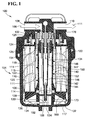
- FIG. 1 is a cross-sectional illustration of an exemplary embodiment of a filter assembly in accordance with the teachings of the present invention
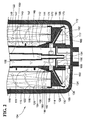
- FIG. 2 is an enlarged illustration of a portion of the filter of the filter assembly of FIG. 1 ;
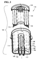
- FIG. 3 is a partially exploded illustration of the filter of FIG. 1 , illustrated in cross-section and perspective;
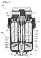
- FIG. 4 is a cross-sectional illustration of a further exemplary embodiment of a filter assembly in accordance with the teachings of the present invention.
- FIG. 5 is an enlarged illustration of a portion of the filter of the filter assembly of FIG. 4 ;
- FIG. 6 is a partially exploded illustration of the filter of FIG. 4 , illustrated in cross-section and perspective;
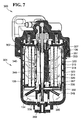
- FIG. 7 is a cross-sectional illustration of a further exemplary embodiment of a filter assembly in accordance with the teachings of the present invention.
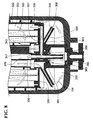
- FIG. 8 is an enlarged illustration of a portion of the filter of the filter assembly of FIG. 7 ;
- FIG. 9 is a partially exploded illustration of the filter of FIG. 7 , illustrated in cross-section and perspective;
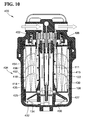
- FIG. 10 is a cross-sectional illustration of a further exemplary embodiment of a filter assembly in accordance with the teachings of the present invention.
- FIG. 11 is an enlarged illustration of a portion of the filter of the filter assembly of FIG. 1 ;
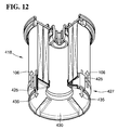
- FIG. 12 is a perspective partial cross-section of the filter element of FIG. 10 .
- FIG. 1 illustrates a first embodiment of a filter assembly 100 according to the teachings of the present invention.
- the filter assembly 100 generally includes a filter base 102 and a filter 104.
- the filter 104 connects to the filter base 104 and acts to filter impurities from fluid passing through the filter assembly 100.
- Dirty fluid enters the filter assembly 100 through a dirty fluid inlet port 108 of the filter base 102.
- Dirty fluid 106 is supplied from a system such as an engine or from a fluid storage tank such as fuel tank (neither shown). After entering and passing through the filter base 102, the dirty fluid 106 passes through the filter 104 and is cleaned. The clean fluid (illustrated as arrows 111) then exits the filter assembly 100 through clean fluid port 110 of the filter base 102 and travels to the system that utilizes the clean fluid.
- the filter 104 of FIG. 1 includes an outer housing 114 having an annular side wall 115 that defines an internal cavity 116 that houses a replaceable filter element 118.
- the filter element 118 includes a tubular ring of filter media 120 which separates impurities from the dirty fluid as it passes therethrough, as illustrated by arrows 122.
- a cover in the form of a top end cap 124 is sealingly connected to a top end 126 of the tubular ring of filter media 120.
- the cover closes an open end of housing 114 opposite a generally closed bottom end wall 117.
- the end cap and cover could be formed as separate components.
- the illustrated filter media 120 is a combination of a pair of concentric rings of filter media.
- alternative filer media could be used.
- a single tubular ring of filter media could be used.
- the sealing connection is generally formed between an inner face 125 of the top end cap 124 and the top end 126 of the ring of filter media 120 to prevent fluid bypass therebetween. By preventing fluid bypass, the dirty fluid 106 is forced to pass through the filter media 120.
- the sealing connection between the top end cap 124 and ring of filter media 120 may be provided by any connection.
- the top end cap 124 may be potted to the ring of filter media 120 using an adhesive such as, for example, Plastisol or epoxy, the ring of filter media 120 may be ultrasonically bonded to the top end cap 124, the ring of filter media 120 may be embedded into the top end cap 124, the end cap 124 may be molded or over molded onto the end of the filter media 120 or any other means of providing a sealing connection may be implemented.
- the bottom end 128 of the ring of filter media 120 is sealingly connected to a bottom end cap 130.
- the bottom end 128 and bottom end cap 130 may be sealingly connected in a similar or different manner as the connection between the top end cap 124 and top end 126.
- top and bottom end caps 124, 130 bound the filter media 120 to prevent bypass or short circuiting of the filter media 120 by dirty fluid 106.
- the bottom end cap 130 forms a portion of a water separating device, illustrated in the form of a cone separator 132 to assist in separating water from the dirty fluid 106 prior to the dirty fluid 106 passing through the filter media 120.
- the separated water illustrated as arrows 134, can then be held in a reservoir 136 between the bottom end cap 130 and the bottom end wall 117 of housing 114 from which the water 134 may ultimately be evacuated from the filter assembly 100 altogether.
- the filter assembly 100 further includes a center tube 140 that is positioned within a internal cavity 142 of the tubular ring of filter media 120.
- the center tube 140 defines outer and inner fluid flow passages 144, 146 that direct separated and oppositely flowing fluid flows of the dirty fluid 106 and separated water 134 between the top and bottom ends 126, 128 of the filter media 120.
- the outer fluid flow passage 144 provides a flow path for dirty fluid 106 through the internal cavity 142 of the filter media 120 to the cone separator 132, while the inner fluid flow passage 146 provides a flow path for the separated water 134 to be evacuated from the filter 104, and ultimately out of the filter base 102.
- the outer and inner flow passages 144, 146 are separated by an annular wall 147 of the center tube 140.
- the annular wall 147 extends into reservoir 136 and acts as a drain pipe to evacuate the separated water 134 from the reservoir 136 and filter 104 more generally.
- a clean fluid cavity 148 is formed between an outer wall 150 of the center tube 140 and an inner side 152 (or clean fluid side) of the ring of filter media 120.
- the outer wall 150 of the center tube 140 separates the outer fluid flow passage 144, through which dirty fluid 106 flows, from the clean fluid cavity 148, to prevent mixing of the dirty and clean fluids 106, 111.
- the top end cap 124 further defines a clean fluid outlet 154, which fluidly communicates the clean fluid cavity 148 with the exterior of the filter 104, and ultimately with the clean fluid port 110 of the filter base 102.
- the clean fluid outlet 154 is in the form of a plurality of apertures that pass axially through the top end cap 124.
- the top end cap 124 forms a cover of the filter 104 which requires clean and dirty fluid 111, 106 to flow therethrough to exit and enter the filter 104.
- the cover may be separate and independent from the end cap 124.
- the center tube 140 includes a cone portion 160 that forms a second portion of the cone separator 132.
- a generally frustoconical bottom surface 162 of the bottom end cap 130 cooperates with a frustoconical top surface 164 of the cone portion 160 of the center tube 140.
- Bottom surface 162 is a generally concave surface, while top surface 164 is a cooperating convex surface.
- the bottom and top surfaces 162, 164 are coalescing surfaces that cooperate to form a generally frustoconical fluid flow passage 168 therebetween.
- the flow passage 168 extends between inlet 170 to outlet 172.
- the flow passage 168 increases in flow path area as the fluid flows radially outward and axially downward from inlet 170 toward outlet 172.
- the increase in area can facilitate a reduction in fluid pressure which promotes slowing of the fluid flow and thus coalescing of water entrained within the dirty fluid 106 such that water will separate from the dirty fluid 106 passing through the fluid flow passage 168.
- the separation of water 134 from the dirty fluid 106 is promoted by the change in fluid flow after the dirty fluid 106 exits outlet 172 due to the differences in densities of the dirty fluid (typically fuel) and water 134.
- Bottom end cap 130 includes a downward extending annular flange 173 that includes an inner surface that forms part of bottom surface 162. This annular flange 173 directs fluid flow toward bottom end wall 117 further increasing the amount of change in fluid flow.
- the annular flange 173, as illustrated, extends axially closer to the bottom end all 117 than a distal end of cone portion 160. Further, the inner surface of annular flange 173, which forms part of surface 164, faces radially inward.
- the top surface or bottom surface 162, 164 may include ribs or other structure to locate bottom end cap 130 relative to cone portion 160 and, more particularly, top surface 164 relative to the bottom surface 162 to maintain the flow passage 168 therebetween. Such ribs may be particularly useful during assembly of filter 104. However, these ribs are not illustrated, nor are they required as the filter element 118 may be located within the housing 114 so as to maintain the flow passage 168 in other ways.
- dirty fluid 106 flows axially through an outer flow path 144 of the center tube 140.
- the dirty fluid 106 exits the outer flow path 144 through ports 174, and enters the frustoconical fluid flow path 168 through inlet portion 170.
- the pressure of the dirty fluid drops 106 due to the change in cross-sectional area of the flow path 178 in the direction of travel toward exit 172.
- the separated water 134 remains in the reservoir 136 while the dirty fluid 106 flows axially back toward the filter base 102 and ultimately through the filter media 120, as illustrated by arrows 122, into clean fluid cavity 148 formed between an inner surface 152 of the filter media and outer wall 150 of the center tube 140.
- the filter element 118 is formed by the filter media 120, top end cap 124 and the bottom end cap 130.
- a top grommet 178 that interacts and interfaces with the filter base 102 is an optional component of the filter element 118.
- the filter element 118 is removable from housing 116, which is reusable, such that it is replaceable when spent.
- the filter element 118 is independent of center tube 140 such that the center tube can be reused. As such, the center tube 140 can be removed from filter element 118.
- the center tube 140 extends through an aperture 180 formed in the bottom end cap 130.
- the aperture 180 is bounded by a lip seal formed by deformable flange 182.
- Flange 182 seals against the outer surface 184 of a radially stepped out portion 186 of the center tube 140.
- the center tube 140 mounts to an axially extending boss 188 of housing 114.
- Center tube 140 includes cavity 190 which receives the distal free end of boss 188.
- Boss 188 includes a flow port 192 that permits the separated water 134 to enter into a cavity of boss 188. Once in the cavity, the separated water 134 may be drawn through the inner flow path 146 of the center tube 140 and evacuated from the filter 104.
- the center tube 140 may be permanently affixed to the boss 188, such that the center tube 140 remains with the housing 114 when the filter element 118 is removed from the housing 114.
- the center tube 140 can be releasably mounted to boss 188 such that the center tube 140 can be easily removed from the housing 114.
- the center tube 140 may be removed as the filter element 118 is removed from the housing 114 or it could be sufficiently secured to boss 188 that it remains with the filter housing 114 as the filter element 118 is removed (see e.g. FIG. 3 ), but it can be removed from the housing by easily pulling on the center tube 140 after the filter element 118 has been removed from housing 114.
- the filter element 118 includes only a portion of the cone separator 132 such that when the filter element 118 is removed from the housing 114, the cone separator 132 is inoperable (such as in the configuration as illustrated in FIG. 3 ). As such, for the cone separator 132 to operate, the filter element 118 must be added to a housing 114 that includes the other portion of the cone separator, namely the bottom cone portion 160.
- boss 188 is formed by a plurality of wall portions and is not a continuous annular wall. However, boss 188 could be formed as continuous ring having water flow ports formed therethrough.
- FIGS. 4-6 A second alternative embodiment of a filter assembly 200 including a filter head 202 and filter 204 according to the teachings of the present invention is illustrated in FIGS. 4-6 .
- the center tube 240 does not directly mount to the filter housing 214. Instead, the center tube 240 forms a part of the filter element 218. As such, when the filter element 218 is replaced, the center tube 240 is similarly replaced.
- the center tube 240 is permanently secured to the filter element 218 as it includes a primary body portion that is axially interposed between the top and bottom end caps 224, 230. However, a portion of the center tube 240, and particularly inner wall 247, extends axially beyond the bottom end cap 230 through an aperture in the bottom end cap 230. This portion extends into reservoir 236 to eventually communicate with any water 134 that is stripped from the dirty fluid 106.
- the cone separator 232 includes a top cone portion 249 and bottom cone portion 260.
- the top and bottom cone portions 249 are independent structures.
- the top cone portion 249 is formed as a separate component independent of bottom end cap 230.
- the bottom cone portion 260 is formed as a separate component independent of center tube 240.
- top and bottom cone portions 249, 260 include frustoconical surfaces 262, 264 and define flow path 268 therebetween (see FIG. 5 ).
- the bottom end cap 230 and top cone portion 249 may be connected to one another by seal member 261.
- the seal member 261 engages a radially inner surface 263 of a central aperture of the bottom end cap 230.
- the seal member 261 also radially engages a radially outer surface 266 of top cone portion 249.
- the bottom end cap 230 includes an axially extending flange 270, which happens to extend axially into the cavity 248 formed by the filter media 220.
- the top cone portion 249 includes a corresponding axially extending flange 272 that is sized smaller than and is received within the axially extending flange 270 of the bottom end cap 230.
- Flange 274 prevents dirty fluid 106 from passing between bottom end cap 230 and the top cone portion 249 and thereby bypass the filter media 220.
- An axially extending flange portion 274 of seal member 261 is radially interposed between the two axially extending flange portions 270, 272 of the bottom end cap 230 and top cone portion 249, respectively.
- the axially extending flange portion 274 may include a resilient protrusion portion that facilitates engagement between seal member 261 the bottom end cap 230 and the top cone portion 249.
- the seal member 261 further includes an inner axially extending flange portion 276 that is radially interposed between inner wall 247 of the center tube 240 and an axially extending flange portion 278 of the bottom cone portion 260 of the cone separator 232.
- the inner flange portion 276 prevents fluid from passing between wall 247 of the center tube 240 and the bottom cone portion 260 which would permit dirty fluid 106 to bypass the flow path 268.
- the bottom cone portion 260 of this embodiment is connected to a bottom end wall 217 of the housing 214.
- the bottom cone portion 260 includes an annular boss or base portion 279 that is received in an annular groove 280 formed in the bottom end wall 217.
- the bottom cone portion 260 may be mechanically secured in the groove 280, such as by snapping, ultrasonic welding, threading, gluing, etc.
- the bottom cone portion 260 may be removable from the housing 214.
- the bottom cone portion 260 could be integrally formed as unitary piece with the housing 214, and particularly end wall 217.
- the top cone portion 249 sealingly engages the inner surface 284 of the sidewall 215 of housing 214.
- the top cone portion 249 includes a radially sealing gasket 286 that seals with the inner surface 284.
- a mounting flange 288 of the top cone portion 249 carries sealing gasket 286.
- the mounting flange 288 includes a plurality of flow ports 289 that permit the dirty fluid 106 that has passed through the fluid flow path 268 to flow axially towards filter media 220 from the reservoir 236.
- the engagement between the top cone portion 249 and sidewall 215 is greater than the engagement between the bottom end cap 230 and the top cone portion 249 such that the top cone portion 249 remains with the housing 214 when the filter element 218 is removed from housing 214.
- the engagement between the top cone portion 249 and the sidewall 215 is less than the engagement between the bottom end cap 230 and the top cone portion 249 such that the top cone portion 249 remains with the filter element 218 when the filter element 218 is removed from housing 214.
- the top cone portion 249 may be removable from the filter element 218 by slightly greater force such that the top cone portion 249 can be reused.
- Filter elements 218 of this embodiment may or may not include the bottom cone portion 249.
- FIGS. 7-9 A further alternative embodiment of a filter assembly 300 including a filter base 302 and filter 304 according to the teachings of the present invention is illustrated in FIGS. 7-9 .
- the filter element 318 further includes an outer water stripping wrapper 322 that that surrounds the filter media 320.
- the water stripping wrapper 322 includes a helical thread 323 that causes the dirty fluid 106 to flow axially a substantial length of the filter media 320 after it exits the cone separator 332.
- the helical thread 323 also causes the dirty fluid 106 to flow angularly as it flows axially toward the filter base 302 from reservoir 336.
- the inclusion of the water stripping wrapper 322 causes additional water 335 that has coalesced to be removed from the dirty fluid flow 106.
- the water stripping wrapper 323 includes flow ports 327 that cause the dirty fluid 106 to undergo a large change in flow direction as it flows from a cavity 351 formed between the sidewall 315 of the housing 314 and the outer surface of the water stripping wrapper 323 to a cavity 353 formed between an inner surface of the water stripping wrapper 323 and an outer surface of the filter media 320.
- the bottom end cap 330 includes a radial flow path 357 formed therein.
- the radial flow path 357 communicates the inner fluid flow path 346 of center tube 340 with cavity 353.
- the inner wall 347 that forms the inner fluid flow path 347 of the center tube 340 includes at least one fluid flow port 363 that permits stripped water 335 to be drawn through radial flow path 357 and into inner flow path 346 to be ultimately removed from the filter 304. Stripped water 335 will join other stripped water 134 that was previously stripped using cone separator 332.
- the top cone portion 349 is integrally formed with bottom end cap 330.
- the top cone portion 349 mates with the bottom cone portion 360 to form flow path 368 (see FIG. 8 ).
- the bottom cone portion 360 includes a central aperture 380 that receives an axially extending annular flange 382 of the bottom end cap 330.
- An o-ring seal 384 forms a radial seal between an inner surface of aperture 380 and the annular flange 382.
- Annular flange 382 forms a central aperture 386 which receives inner wall 347 of center tube 340 therethrough. When assembled, the inner wall 347 extends through annular flange 382 of the bottom end cap 330 and into reservoir 336 of the filter 304.
- FIGS. 10 and 11 A further embodiment of a filter assembly 400 having a filter base 402 and filter 404 is illustrated in FIGS. 10 and 11 .
- This embodiment is similar to the embodiment of FIGS. 4-6 .
- the filter element 418 of this embodiment includes a plurality of water flow ports 425 that are angularly spaced around the filter element 418. Adjacent ones of the water flow ports 425 are separated by and define therebetween dirty fluid flow paths 427.
- the dirty fluid flow paths 427 extend angularly between adjacent ones of the stripped water flow ports 425 and radially between the sidewall 415 of housing 414 and bottom end cap 430.
- Both the stripped water flow ports 425 and the dirty fluid flow paths 427 communicate the reservoir 436 with the cavity 452 formed between the inner surface 454 of sidewall 415 and the outer surface 456 of the filter media.
- the dirty fluid flow paths 427 are focused on permitting the dirty fluid 106 to flow from the reservoir 436 to cavity 452.
- the water flow ports 425 are focused on permitting water 435 that was not previously stripped by cone separator 432 that is subsequently stripped from the dirty fluid 106 as it passes through the filter media to settle into reservoir 436.
- the dirty fluid flow paths 427 experience a larger fluid flow and are provided with large flow areas.
- water flow ports 425 can provide radial support for the filter element 418 at the bottom end cap 430 end of the filter element 418 when mounted within housing 414.
- filters and filter elements incorporate water separators configured to have fluid flow paths in the shape of a cone or similarly shaped, it is contemplated that the water separators could have the fluid flow paths be generally planar such that the paths are generally planar in the form of an annular disc.
Landscapes
- Chemical & Material Sciences (AREA)
- Chemical Kinetics & Catalysis (AREA)
- Lubrication Details And Ventilation Of Internal Combustion Engines (AREA)
- Filtration Of Liquid (AREA)
- Separation Using Semi-Permeable Membranes (AREA)
Applications Claiming Priority (1)
| Application Number | Priority Date | Filing Date | Title |
|---|---|---|---|
| US12/139,606 US8815090B2 (en) | 2008-06-16 | 2008-06-16 | Filter with water separation device |
Publications (1)
| Publication Number | Publication Date |
|---|---|
| EP2135659A1 true EP2135659A1 (fr) | 2009-12-23 |
Family
ID=40967152
Family Applications (1)
| Application Number | Title | Priority Date | Filing Date |
|---|---|---|---|
| EP09162694A Ceased EP2135659A1 (fr) | 2008-06-16 | 2009-06-15 | Filtre et dispositif de séparation de l'eau |
Country Status (7)
| Country | Link |
|---|---|
| US (1) | US8815090B2 (fr) |
| EP (1) | EP2135659A1 (fr) |
| JP (1) | JP2009297713A (fr) |
| AU (1) | AU2009202393A1 (fr) |
| BR (1) | BRPI0901774A2 (fr) |
| CA (1) | CA2669020A1 (fr) |
| MX (1) | MX2009006382A (fr) |
Cited By (6)
| Publication number | Priority date | Publication date | Assignee | Title |
|---|---|---|---|---|
| WO2015102822A1 (fr) * | 2014-01-02 | 2015-07-09 | Caterpillar Inc. | Élément filtrant ayant une double capacité de filtration et ensemble filtre |
| WO2015112370A1 (fr) * | 2014-01-24 | 2015-07-30 | Caterpillar Inc. | Élément de filtre doté d'une partie couvercle et ensemble filtre |
| WO2015112520A1 (fr) * | 2014-01-24 | 2015-07-30 | Caterpillar Inc. | Élément de filtre possédant un tube de mise à l'air et ensemble de filtre |
| EP3067102A1 (fr) | 2015-03-11 | 2016-09-14 | Mann + Hummel Gmbh | Separateur d'eau et systeme de separation d'eau comprenant un dispositif d'evacuation d'eau integre |
| EP3528920A4 (fr) * | 2016-10-21 | 2020-04-22 | Cummins Filtration IP, Inc. | Système d'étanchéité faciale pour un filtre |
| CN115559798A (zh) * | 2022-12-06 | 2023-01-03 | 河南平和滤清器有限公司 | 一种内置离心分离结构的机油滤清器 |
Families Citing this family (16)
| Publication number | Priority date | Publication date | Assignee | Title |
|---|---|---|---|---|
| DE102011088742A1 (de) | 2011-12-15 | 2013-06-20 | Mahle International Gmbh | Filtereinrichtung |
| US8991619B2 (en) | 2012-03-26 | 2015-03-31 | Baldwin Filters, Inc. | Filter assembly with water evacuation and methods |
| US9427685B2 (en) | 2012-09-20 | 2016-08-30 | Ford Global Technologies, Llc | Suction filter media overmolded integrally with tray |
| ITRE20120066A1 (it) * | 2012-10-11 | 2014-04-12 | Ufi Filters Spa | Cartuccia filtrante dotata di mezzi per lo spurgo dell'acqua e relativo gruppo filtrante |
| EP2925997A4 (fr) * | 2012-11-30 | 2016-08-24 | Thermo King Corp | Systèmes et procédés de régulation d'une pression dans un système de distribution de carburant |
| DE102013202718B4 (de) * | 2013-02-20 | 2021-08-26 | Robert Bosch Gmbh | Filtervorrichtung mit einem Partikelfilter und einem Wasserabscheider und Verwendung einer derartigen Filtervorrichtunq |
| US9546626B2 (en) | 2013-03-06 | 2017-01-17 | Parker-Hannifin Corporation | Depth coalescing filter with barrier media patch |
| BR102013011662A2 (pt) * | 2013-05-10 | 2015-06-30 | Mahle Metal Leve Sa | Filtro |
| US10184415B2 (en) * | 2013-10-16 | 2019-01-22 | Cummins Filtration Ip, Inc. | Electronic filter detection feature for liquid filtration systems |
| US9527018B2 (en) * | 2014-04-01 | 2016-12-27 | Caterpillar Inc. | Debris drain filter system and cartridge |
| DE102014212923A1 (de) * | 2014-07-03 | 2016-01-07 | Mahle International Gmbh | Filtereinrichtung |
| US11035330B2 (en) * | 2015-10-16 | 2021-06-15 | MANN+HUMMEL Filtration Technology Group Inc. | Filter element with air-bleed conduit |
| CN106669263A (zh) * | 2016-11-23 | 2017-05-17 | 盐城市星火阀业制造有限公司 | 一种增压式过滤阀 |
| WO2019084440A1 (fr) * | 2017-10-27 | 2019-05-02 | Cummins Filtration Ip, Inc. | Module intégré avec filtres d'étage un et d'étage deux combinés dans un seul boîtier |
| EP4034283B1 (fr) * | 2019-09-27 | 2024-04-03 | Parker-Hannifin Corporation | Plissage en étoile avec écoulement à l'intérieur vers l'extérieur ayant un drainage d'eau à travers le centre |
| CN216604353U (zh) * | 2021-10-25 | 2022-05-27 | 上海聚蓝水处理科技有限公司 | 插接式房车水箱过滤器 |
Citations (5)
| Publication number | Priority date | Publication date | Assignee | Title |
|---|---|---|---|---|
| US3931011A (en) * | 1973-11-19 | 1976-01-06 | Racor Industries, Inc. | Fluid separation apparatus |
| US4017397A (en) | 1974-12-02 | 1977-04-12 | Copeland Shannon B | Filter device for diesel engines |
| GB2114237A (en) * | 1982-01-23 | 1983-08-17 | Lucas Ind Plc | Fuel treatment device |
| US5938921A (en) * | 1997-07-30 | 1999-08-17 | Stanadyne Automotive Corp. | Water baffle for filter cartridge |
| EP1124056A2 (fr) * | 2000-02-12 | 2001-08-16 | Robert Bosch Gmbh | Filtre à carburant |
Family Cites Families (120)
| Publication number | Priority date | Publication date | Assignee | Title |
|---|---|---|---|---|
| US1761924A (en) | 1927-11-02 | 1930-06-03 | Ac Spark Plug Co | Oil filter |
| GB1036350A (en) | 1964-07-17 | 1966-07-20 | Gen Motors Ltd | Filter units for liquid filters |
| US3384241A (en) | 1966-01-12 | 1968-05-21 | Nefco Filter Corp | Graduated dual density liquid filter element |
| US3370708A (en) | 1966-03-16 | 1968-02-27 | Champion Lab Inc | Dual element, dual valve, twist-on type filter assembly |
| US3333624A (en) | 1966-06-20 | 1967-08-01 | Southwire Co | Casting wheel cooling method |
| US3988244A (en) | 1975-06-30 | 1976-10-26 | Sta-Rite Industries, Inc. | Cartridge filter |
| JPS5541284Y2 (fr) * | 1978-05-25 | 1980-09-27 | ||
| JPS5727550Y2 (fr) * | 1979-01-10 | 1982-06-16 | ||
| US4372847A (en) | 1980-06-23 | 1983-02-08 | Chicago Rawhide Manufacturing Company | Fuel filter assembly and cartridge |
| US4812235A (en) | 1982-03-29 | 1989-03-14 | Hr Textron, Inc. | Filter element assembly replaceable mesh pack |
| US4719012A (en) | 1986-05-30 | 1988-01-12 | Caterpillar Inc. | Twist on disposable filter |
| GB2222534B (en) | 1988-09-09 | 1992-11-25 | Process Scient Innovations | Filter assembly and cartridge therefor |
| US4915831A (en) | 1989-01-23 | 1990-04-10 | Cuno, Incorporated | Filter assembly featuring displaceable filter head plunger for locking into filter cartridge detent |
| FR2648730B1 (fr) * | 1989-06-21 | 1992-06-12 | Alsthom Gec | Separateur centrifuge pour liquide figeable, notamment pour gazole |
| US5078877A (en) | 1989-09-25 | 1992-01-07 | Baldwin Filters, Inc. | Dual flow and dual stage lubricant filter assembly |
| IT1240537B (it) | 1990-08-08 | 1993-12-17 | Gilardini Spa | Filtro per combustibile di motore a combustione interna, con coperchioa fissaggio rapido |
| DE4026934A1 (de) | 1990-08-25 | 1992-03-05 | Seitz Filter Werke | Traegerrohr als bauteil fuer filtermodule |
| US5203994A (en) | 1991-08-16 | 1993-04-20 | Stanadyne Automotive Corp. | Fuel filter retention system |
| US5350506A (en) | 1992-01-30 | 1994-09-27 | Navistar International Transporation Corporation | Anti-drain fluid filter |
| DE4204354A1 (de) | 1992-02-14 | 1993-08-19 | Basf Magnetics Gmbh | Filtervorrichtung |
| US5215658A (en) | 1992-03-02 | 1993-06-01 | Ingersoll-Rand Company | Cartridge ejector device for fluid compression system |
| US5302284A (en) | 1992-12-23 | 1994-04-12 | Stanadyne Automotive Corp. | Fuel filter with spring-loaded retention system |
| US5336406A (en) | 1993-01-26 | 1994-08-09 | Elkay Manufacturing Company | Replaceable filter cartridge and head assembly with safety shut-off valve |
| US5339787A (en) | 1993-02-26 | 1994-08-23 | Westinghouse Electric Corporation | Method and apparatus for distributing fuel in a diesel engine |
| DE4310492A1 (de) | 1993-03-31 | 1994-10-06 | Hydac Filtertechnik Gmbh | Filtervorrichtung mit Keyportanschluß |
| US5783067A (en) | 1993-04-13 | 1998-07-21 | Facet International, Inc. | Elongated filter system, filter element therefor and methods of making same |
| US5362390A (en) | 1993-06-28 | 1994-11-08 | Fleetguard, Inc. | Shut-off valve for spin-on filters |
| US5342511A (en) | 1993-07-06 | 1994-08-30 | Baldwin Filters, Inc. | Oil filter with inner and outer coaxial filter elements |
| US6113781A (en) | 1993-09-15 | 2000-09-05 | Parker-Hannifin Corporation | Fuel filter with dual flow |
| US5462658A (en) | 1994-01-14 | 1995-10-31 | Thermo King Corporation | Fuel filter system |
| US5390701A (en) | 1994-04-06 | 1995-02-21 | Lessley; Michael R. | Filter valve assembly |
| US5817234A (en) | 1995-04-13 | 1998-10-06 | Advanced Performance Technology, Inc. | Fluid filter and method for assembling same |
| US5591332A (en) | 1995-05-25 | 1997-01-07 | Omnipure Filter Co. | Filter assembly with automatic shut-off and quick-connect filter cartridge |
| US5637215A (en) * | 1995-10-18 | 1997-06-10 | Purolator Products Company | Fuel filter having improved communication with a contaminant container |
| US5788859A (en) * | 1996-05-10 | 1998-08-04 | Baldwin Filters, Inc. | Self-evacuating water-separating fuel filter |
| US5698093A (en) | 1996-05-31 | 1997-12-16 | Eagle Filter Corporation | Gasoline filter with automatic shut off |
| US5868932A (en) | 1996-07-20 | 1999-02-09 | Fleetguard, Inc. | Fiber with reusable shell and center tube |
| US6207052B1 (en) | 1996-07-26 | 2001-03-27 | Garth T. Webb | Method and apparatus for removing air locks within manually operated micro-filtration devices |
| US5753107A (en) | 1996-08-08 | 1998-05-19 | Wtc Ecomaster Corporation | Dripless purification manifold and cartridge |
| US5674393A (en) | 1996-08-13 | 1997-10-07 | Ralph Terhune | Oil filter |
| US5837137A (en) | 1996-08-21 | 1998-11-17 | Stanadyne Automotive Corp. | Base/cartridge location and key system for fuel filter assembly |
| JPH10110657A (ja) | 1996-08-22 | 1998-04-28 | Stanadyne Automot Corp | 整合カートリッジ支持構造を備えたフィルター・ アセンブリイ |
| JP3692655B2 (ja) | 1996-10-07 | 2005-09-07 | 株式会社デンソー | エレメント交換型フィルタ |
| US5766468A (en) | 1997-01-06 | 1998-06-16 | Baldwin Filters, Inc. | Dual media primary/secondary fuel filter |
| DE19700564A1 (de) | 1997-01-10 | 1998-07-16 | Mann & Hummel Filter | Filter, insbesondere für das Schmieröl einer Brennkraftmaschine |
| US5906737A (en) | 1997-05-01 | 1999-05-25 | Hoeppner; Michael A. | Filter core system |
| US6006924A (en) | 1997-05-14 | 1999-12-28 | Pti Technologies, Inc. | Multi-media filtration system with reusable and demountable filter cartridge |
| US6068763A (en) | 1997-09-12 | 2000-05-30 | Purolator Products Company | Spin-on oil filter with replaceable element |
| US5988399A (en) | 1997-12-23 | 1999-11-23 | Baldwin Filters, Inc. | Spin-on filter |
| SE513489C2 (sv) | 1998-10-23 | 2000-09-18 | Volvo Lastvagnar Ab | Vätskefilter |
| NL1012004C2 (nl) | 1999-05-07 | 2000-11-13 | Asm Int | Werkwijze voor het verplaatsen van wafers alsmede ring. |
| US6189513B1 (en) | 1999-06-03 | 2001-02-20 | Ford Global Technologies, Inc. | Fuel transfer and conditioning unit for automotive vehicle |
| US6673250B2 (en) | 1999-06-21 | 2004-01-06 | Access Business Group International Llc | Radio frequency identification system for a fluid treatment system |
| US6187188B1 (en) | 1999-07-19 | 2001-02-13 | Stanadyne Automotive Corp. | Filter cartridge retention system |
| EP1210164B2 (fr) | 1999-08-12 | 2011-09-07 | Purolator Products NA, Inc. | Filtre a huile avec tube central a fixation par pression integree |
| DE29918105U1 (de) | 1999-10-14 | 1999-12-23 | Mann & Hummel Filter | Filterpatrone mit Mittelrohr |
| IT248285Y1 (it) * | 1999-11-08 | 2002-12-16 | Ufi Universal Filter Int Spa | Filtro per carburante. |
| BR0015564B1 (pt) * | 1999-12-03 | 2010-02-23 | elemento de filtro e montagem de filtro. | |
| US20050000876A1 (en) | 1999-12-03 | 2005-01-06 | Knight Steven R. | Keyed latch valve for fuel filter |
| US6495042B1 (en) | 1999-12-03 | 2002-12-17 | Parker-Hannifin Corporation | Filter cartridge for a fuel filter having a keyed latch shut-off valve |
| DE19960600A1 (de) | 1999-12-16 | 2001-06-21 | Bosch Gmbh Robert | Flüssigkeitsfilter |
| DE19961580A1 (de) | 1999-12-21 | 2001-06-28 | Mann & Hummel Filter | Flüssigkeitsfilter mit Ablaß für Flüssigkeitsrückstände |
| EP1125621B1 (fr) | 2000-02-16 | 2006-10-04 | Stanadyne Corporation | Filtre écologique à cartouche pour carburant et l'ensemble filtre |
| US6506302B2 (en) | 2000-02-16 | 2003-01-14 | Stanadyne Corporation | Key system for ecological filter cartridge and element |
| US6500335B2 (en) | 2000-02-16 | 2002-12-31 | Stanadyne Corporation | Filter system base module with self-locking cartridge retainer |
| US6458269B1 (en) | 2000-04-20 | 2002-10-01 | Cuno Incorporated | Keyed filter assembly |
| DE10030037A1 (de) | 2000-06-17 | 2001-12-20 | Mann & Hummel Filter | Zylindrische Filterpatrone mit Stützrohr |
| NZ524594A (en) | 2000-08-11 | 2004-07-30 | Roger P Reid | Keyed system for connection of filter cartridge to filter holder |
| US6428700B1 (en) * | 2000-09-06 | 2002-08-06 | Baldwin Filters, Inc. | Disposable centrifuge cartridge backed up by reusable cartridge casing in a centrifugal filter for removing soot from engine oil |
| US6387259B1 (en) | 2000-11-27 | 2002-05-14 | Dana Corporation | Spin-on filter assemblies |
| WO2002076575A2 (fr) | 2001-03-21 | 2002-10-03 | Cuno Incorporated | Ensemble de filtre et procede de fabrication |
| US6544412B2 (en) | 2001-03-28 | 2003-04-08 | Champion Laboratories, Inc. | Filter including temperature and pressure responsive bypass |
| WO2002078816A1 (fr) | 2001-04-02 | 2002-10-10 | Donaldson Company, Inc. | Filtre a cartouche a cloche a mecanisme de verrouillage et procedes associes |
| MXPA03009907A (es) * | 2001-05-02 | 2004-01-29 | Parker Hannifin Corp | Elemento de filtro giratorio y cabeza de filtro. |
| US20020185454A1 (en) | 2001-05-17 | 2002-12-12 | Beard John H. | Full flow particulate and acid-neutralizing filter |
| US20030019819A1 (en) | 2001-07-30 | 2003-01-30 | Karl Fritze | Hot disconnect replaceable water filter assembly |
| US6652740B2 (en) | 2001-09-10 | 2003-11-25 | Honeywell International Inc. | Pressure sensing fluid filter system |
| US7638042B2 (en) | 2002-02-15 | 2009-12-29 | 3M Innovative Properties Company | System for monitoring the performance of fluid treatment cartridges |
| US6740234B1 (en) | 2002-03-05 | 2004-05-25 | Stanadyne Corporation | Key track system |
| US6770196B2 (en) | 2002-03-20 | 2004-08-03 | Arvin Technologies, Inc. | Filter cap with releasable filter element |
| US7081201B2 (en) | 2002-04-19 | 2006-07-25 | 3M Innovative Properties Company | Encapsulated filter cartridge |
| US6565746B1 (en) | 2002-04-30 | 2003-05-20 | Dana Corporation | One-piece self-venting drain valve |
| US7168573B2 (en) | 2002-06-07 | 2007-01-30 | Baldwin Filters, Inc. | Environmentally friendly filter cartridge |
| GB2389322B (en) | 2002-06-07 | 2005-08-17 | Baldwin Filters Inc | Environmentally friendly dual lube venturi filter cartridge |
| USD472604S1 (en) | 2002-08-22 | 2003-04-01 | Pentapure Incorporated | Filter manifold connector |
| USD472299S1 (en) | 2002-08-22 | 2003-03-25 | Pentapure Incorporated | Filter cartridge connector |
| US6881334B2 (en) | 2002-10-31 | 2005-04-19 | Stanadyne Corporation | Eccentric interference retention system for a filter cartridge |
| US6863811B2 (en) | 2002-10-31 | 2005-03-08 | Stanadyne Corporation | Filter cartridge incorporating a peripheral compatibility matrix |
| WO2004069376A2 (fr) | 2003-01-28 | 2004-08-19 | Donaldson Company, Inc. | Ensemble de filtre et procédés |
| US6896803B2 (en) | 2003-03-28 | 2005-05-24 | Arvin Technologies, Inc. | Filter apparatus and associated method |
| ITRE20030033A1 (it) | 2003-03-31 | 2004-10-01 | Ufi Filters Spa | "basamento per cartuccia filtrante per motori a combustione interna" |
| US6926827B2 (en) | 2003-05-02 | 2005-08-09 | Champion Laboratories, Inc. | Fuel dispenser filter with removable filter media |
| US6962256B2 (en) | 2003-05-27 | 2005-11-08 | Arvin Technologies, Inc. | Plastic molded center tube assembly |
| US7042346B2 (en) | 2003-08-12 | 2006-05-09 | Gaige Bradley Paulsen | Radio frequency identification parts verification system and method for using same |
| JP2005061383A (ja) * | 2003-08-20 | 2005-03-10 | Tokyo Roki Co Ltd | フィルタ装置 |
| JP2007504948A (ja) | 2003-09-12 | 2007-03-08 | スリーエム イノベーティブ プロパティーズ カンパニー | 非崩壊性デュアルフィルタエレメント |
| US7175761B2 (en) | 2003-11-18 | 2007-02-13 | Champion Laboratories, Inc. | Fluid filter assembly |
| JP4129980B2 (ja) * | 2003-11-19 | 2008-08-06 | 株式会社デンソー | 燃料フィルタ |
| US20050161378A1 (en) | 2004-01-23 | 2005-07-28 | Cline L. S. | Two piece elastomer relief and anti-drain back valves for filter |
| WO2005079947A2 (fr) | 2004-02-19 | 2005-09-01 | Stryker Instruments | Ensemble de collecteur et de filtre a panier-filtre |
| US7481917B2 (en) | 2004-03-05 | 2009-01-27 | Hydranautics | Filtration devices with embedded radio frequency identification (RFID) tags |
| US20060006124A1 (en) | 2004-07-12 | 2006-01-12 | Yates Brian G | Filter cartridge and method and apparatus for replacing same |
| US7326342B2 (en) | 2004-09-13 | 2008-02-05 | Baldwin Filters, Inc. | Fuel filter cartridge and keyed end cap |
| US20060096934A1 (en) | 2004-11-05 | 2006-05-11 | Weinberger Keith R | Oil filter assembly |
| DE102004058885B4 (de) | 2004-12-06 | 2016-12-22 | Mann + Hummel Gmbh | Füssigkeitsfilter |
| US20060151371A1 (en) | 2005-01-11 | 2006-07-13 | Weinberger Keith R | Oli filter assembly |
| DE102005005848A1 (de) | 2005-02-08 | 2006-08-10 | Mann + Hummel Gmbh | Filtersystem für Kraftstoff |
| US20060219626A1 (en) | 2005-02-15 | 2006-10-05 | Mann & Hummel Gmbh | Filter system with canister filter element |
| US7744758B2 (en) | 2005-02-15 | 2010-06-29 | Mann + Hummel Gmbh | Liquid filter |
| US7481926B2 (en) | 2005-02-15 | 2009-01-27 | Mann & Hummel Gmbh | Filter device |
| US7387726B2 (en) | 2005-02-15 | 2008-06-17 | Mann & Hummel Gmbh | Liquid filter system |
| ATE505246T1 (de) | 2005-02-22 | 2011-04-15 | Baldwin Filters Inc | Filtervorrichtung |
| US8057669B2 (en) | 2005-02-22 | 2011-11-15 | Baldwin Filters, Inc. | Filter element and filter assembly including locking mechanism |
| DE202005007871U1 (de) | 2005-05-13 | 2006-09-21 | Mann + Hummel Gmbh | Filtereinrichtung, insbesondere zur Flüssigkeitsfilterung in Brennkraftmaschinen |
| DE202005007872U1 (de) | 2005-05-13 | 2006-09-21 | Mann + Hummel Gmbh | Filtereinrichtung, insbesondere zur Flüssigkeitsfilterung in Brennkraftmaschinen |
| US20070095744A1 (en) | 2005-11-01 | 2007-05-03 | Bagci Ismail C | Fluid filter with open-end flow, replaceable cartridge |
| DE102007009352B4 (de) | 2007-02-23 | 2018-03-08 | Mahle International Gmbh | Flüssigkeitsfilter |
| US9211488B2 (en) | 2007-07-13 | 2015-12-15 | Cummins Filtration Ip, Inc. | Fluid filter with localized flow attachment |
| US8241493B2 (en) | 2008-06-16 | 2012-08-14 | Baldwin Filters, Inc. | Filter with ejection mechanism |
| US8128819B2 (en) | 2008-06-16 | 2012-03-06 | Baldwin Filters Inc. | Fluid filter, fluid filter assembly, and mounting method |
-
2008
- 2008-06-16 US US12/139,606 patent/US8815090B2/en active Active
-
2009
- 2009-06-15 MX MX2009006382A patent/MX2009006382A/es not_active Application Discontinuation
- 2009-06-15 CA CA002669020A patent/CA2669020A1/fr not_active Abandoned
- 2009-06-15 EP EP09162694A patent/EP2135659A1/fr not_active Ceased
- 2009-06-16 BR BRPI0901774-7A patent/BRPI0901774A2/pt not_active Application Discontinuation
- 2009-06-16 AU AU2009202393A patent/AU2009202393A1/en not_active Abandoned
- 2009-06-16 JP JP2009143043A patent/JP2009297713A/ja active Pending
Patent Citations (6)
| Publication number | Priority date | Publication date | Assignee | Title |
|---|---|---|---|---|
| US3931011A (en) * | 1973-11-19 | 1976-01-06 | Racor Industries, Inc. | Fluid separation apparatus |
| US3931011B1 (fr) * | 1973-11-19 | 1990-01-09 | Parker Hannifin Corp | |
| US4017397A (en) | 1974-12-02 | 1977-04-12 | Copeland Shannon B | Filter device for diesel engines |
| GB2114237A (en) * | 1982-01-23 | 1983-08-17 | Lucas Ind Plc | Fuel treatment device |
| US5938921A (en) * | 1997-07-30 | 1999-08-17 | Stanadyne Automotive Corp. | Water baffle for filter cartridge |
| EP1124056A2 (fr) * | 2000-02-12 | 2001-08-16 | Robert Bosch Gmbh | Filtre à carburant |
Cited By (11)
| Publication number | Priority date | Publication date | Assignee | Title |
|---|---|---|---|---|
| WO2015102822A1 (fr) * | 2014-01-02 | 2015-07-09 | Caterpillar Inc. | Élément filtrant ayant une double capacité de filtration et ensemble filtre |
| WO2015112370A1 (fr) * | 2014-01-24 | 2015-07-30 | Caterpillar Inc. | Élément de filtre doté d'une partie couvercle et ensemble filtre |
| WO2015112520A1 (fr) * | 2014-01-24 | 2015-07-30 | Caterpillar Inc. | Élément de filtre possédant un tube de mise à l'air et ensemble de filtre |
| US9527016B2 (en) | 2014-01-24 | 2016-12-27 | Caterpillar Inc. | Filter element having vent tube and filter assembly |
| US9527017B2 (en) | 2014-01-24 | 2016-12-27 | Caterpillar Inc. | Filter element having cover portion and filter assembly |
| EP3067102A1 (fr) | 2015-03-11 | 2016-09-14 | Mann + Hummel Gmbh | Separateur d'eau et systeme de separation d'eau comprenant un dispositif d'evacuation d'eau integre |
| DE102015003097A1 (de) | 2015-03-11 | 2016-09-15 | Mann + Hummel Gmbh | Wasserabscheider und Wasserabscheidesystem mit integrierter Wasseraustragseinrichtung |
| CN105964011A (zh) * | 2015-03-11 | 2016-09-28 | 曼·胡默尔有限公司 | 具有整体式排水机构的水分离器和水分离系统 |
| EP3528920A4 (fr) * | 2016-10-21 | 2020-04-22 | Cummins Filtration IP, Inc. | Système d'étanchéité faciale pour un filtre |
| US11446595B2 (en) | 2016-10-21 | 2022-09-20 | Cummins Filtration Ip, Inc. | Facial sealing system for a filter |
| CN115559798A (zh) * | 2022-12-06 | 2023-01-03 | 河南平和滤清器有限公司 | 一种内置离心分离结构的机油滤清器 |
Also Published As
| Publication number | Publication date |
|---|---|
| US20090308803A1 (en) | 2009-12-17 |
| AU2009202393A1 (en) | 2010-01-07 |
| CA2669020A1 (fr) | 2009-12-16 |
| MX2009006382A (es) | 2010-01-15 |
| BRPI0901774A2 (pt) | 2010-04-13 |
| US8815090B2 (en) | 2014-08-26 |
| JP2009297713A (ja) | 2009-12-24 |
Similar Documents
| Publication | Publication Date | Title |
|---|---|---|
| US8815090B2 (en) | Filter with water separation device | |
| CA2700363C (fr) | Systemes de fixation de boitier de cartouche filtrante | |
| EP2830734B1 (fr) | Ensemble filtre à évacuation d'eau | |
| CA2669005C (fr) | Filtre a fluideo ensemble a filtre a fluide et methode d'assemblage | |
| CN106948983B (zh) | 合并式过滤元件 | |
| US7731845B2 (en) | Fuel filter | |
| EP2678092B1 (fr) | Élément filtrant à étages multiples | |
| US8034240B2 (en) | Coalescing element | |
| US20140251889A1 (en) | Depth coalescing filter with barrier media patch | |
| US20180290086A1 (en) | Fuel Filter | |
| CN111148560B (zh) | 用于悬挂在过滤器头上的具有排放功能的过滤器元件和过滤器系统 | |
| WO2018186848A1 (fr) | Filtre à carburant | |
| US20240173653A1 (en) | Bowl filter cartridge arrangement having trap and methods |
Legal Events
| Date | Code | Title | Description |
|---|---|---|---|
| PUAI | Public reference made under article 153(3) epc to a published international application that has entered the european phase |
Free format text: ORIGINAL CODE: 0009012 |
|
| AK | Designated contracting states |
Kind code of ref document: A1 Designated state(s): AT BE BG CH CY CZ DE DK EE ES FI FR GB GR HR HU IE IS IT LI LT LU LV MC MK MT NL NO PL PT RO SE SI SK TR |
|
| 17P | Request for examination filed |
Effective date: 20100611 |
|
| 17Q | First examination report despatched |
Effective date: 20101223 |
|
| STAA | Information on the status of an ep patent application or granted ep patent |
Free format text: STATUS: THE APPLICATION HAS BEEN REFUSED |
|
| 18R | Application refused |
Effective date: 20130316 |