EP2135227B1 - System und verfahren zum detektieren von fluid in einem anschlussblockbereich einer einsatzorteinrichtung - Google Patents
System und verfahren zum detektieren von fluid in einem anschlussblockbereich einer einsatzorteinrichtung Download PDFInfo
- Publication number
- EP2135227B1 EP2135227B1 EP07862346.9A EP07862346A EP2135227B1 EP 2135227 B1 EP2135227 B1 EP 2135227B1 EP 07862346 A EP07862346 A EP 07862346A EP 2135227 B1 EP2135227 B1 EP 2135227B1
- Authority
- EP
- European Patent Office
- Prior art keywords
- voltage magnitude
- field device
- test signal
- terminal block
- fluid
- Prior art date
- Legal status (The legal status is an assumption and is not a legal conclusion. Google has not performed a legal analysis and makes no representation as to the accuracy of the status listed.)
- Not-in-force
Links
Images


Classifications
-
- G—PHYSICS
- G01—MEASURING; TESTING
- G01M—TESTING STATIC OR DYNAMIC BALANCE OF MACHINES OR STRUCTURES; TESTING OF STRUCTURES OR APPARATUS, NOT OTHERWISE PROVIDED FOR
- G01M3/00—Investigating fluid-tightness of structures
- G01M3/02—Investigating fluid-tightness of structures by using fluid or vacuum
- G01M3/04—Investigating fluid-tightness of structures by using fluid or vacuum by detecting the presence of fluid at the leakage point
- G01M3/16—Investigating fluid-tightness of structures by using fluid or vacuum by detecting the presence of fluid at the leakage point using electric detection means
-
- G—PHYSICS
- G01—MEASURING; TESTING
- G01M—TESTING STATIC OR DYNAMIC BALANCE OF MACHINES OR STRUCTURES; TESTING OF STRUCTURES OR APPARATUS, NOT OTHERWISE PROVIDED FOR
- G01M3/00—Investigating fluid-tightness of structures
- G01M3/40—Investigating fluid-tightness of structures by using electric means, e.g. by observing electric discharges
-
- H—ELECTRICITY
- H05—ELECTRIC TECHNIQUES NOT OTHERWISE PROVIDED FOR
- H05K—PRINTED CIRCUITS; CASINGS OR CONSTRUCTIONAL DETAILS OF ELECTRIC APPARATUS; MANUFACTURE OF ASSEMBLAGES OF ELECTRICAL COMPONENTS
- H05K7/00—Constructional details common to different types of electric apparatus
- H05K7/14—Mounting supporting structure in casing or on frame or rack
- H05K7/1462—Mounting supporting structure in casing or on frame or rack for programmable logic controllers [PLC] for automation or industrial process control
Definitions
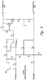
- FIG. 3 is a circuit diagram illustrating an embodiment of current regulator circuit 30, located within communication chipset 28 (shown in FIG. 2 ), that converts input provided by microprocessor 26 (also shown in FIG. 2 ) to either an analog signal that is provided to the control room using the 4-20mA loop current or a digital signal.
- Current regulator circuit 30 includes input terminal VTXA and input terminals VMSB, capacitors C1, C2, C3, C4 and C5, resistors R0 (also referred to as current regulator resistor R0), R1, R2, R3, R4, R5, R6, R7, R8, and R9, operational amplifier OpAmpl, transistors Q1 and Q2, and output terminals +PWR and -PWR that connect to terminals 18a and 18b.
- Input is provided by microprocessor 26 at input terminals VTXA and VMSB, and output is provided to the control room via output terminals +PWR and -PWR.
- Current regulator circuit 30 regulates the current generated through resistor R0 based on the inputs received at input terminals VTXA and VMSB.
- the signal provided by microprocessor 26 to input terminal VMSB represents the sensed process variable, and the magnitude of the signal provided to input terminal VMSB dictates the magnitude of the 4-20mA current provided through resistor R0. That is, current regulation circuit 30 varies the current provided through resistor R0 between 4mA and 20mA based on the signal provided at input terminal VMSB.
- leakage resistor R L The presence of fluid between terminals 18a and 18b can be modeled by a leakage resistor R L , leakage capacitor C L , and fluid resistor R F .
- Leakage resistor R L and leakage capacitor C L model the interface between a fluid and a terminal, and are typically large.
- leakage resistor R L may have a value of approximately one megohm (M ⁇ )
- leakage capacitor may have a value of approximately one microfarad ( ⁇ F).
- Fluid resistance varies depending on the fluid, but is typically lower than the leakage resistance (for example, one kilohm (k ⁇ )).
- the large leakage resistance and leakage capacitance result in DC signals being relatively unaffected by the presence of fluid in terminal block area 17.
- the overall impedance i.e., the combination of resistance and capacitance
- the overall impedance i.e., the combination of resistance and capacitance
- current regulation circuit 30 For example, if field device 10 communicates using the HART standard, then current regulation circuit 30 generates a ⁇ 0.5 mA AC test current at either 1200 Hz or 2400 Hz. For the situation in which no fluid is present within terminal block area 12 (i.e., no terminal leakage), the leakage resistor R L , leakage capacitor C L and fluid resistor R f are removed from the circuit. If cable capacitance C C is not taken into account, then a ⁇ 0.5 mA AC test current generated at 2400 Hz by current regulation circuit 30 results in ⁇ 125 mV signal being generated across measurement resistor R M1 (assuming resistor R M1 has a value of approximately 250 ohms).
- leakage resistor RL leakage capacitance CL, and fluid resistance Rf are connected between terminals 18a and 18b as shown in FIG. 4 .
- a ⁇ 0.5mA AC test current generated by current regulation circuit 30 at 2400 Hz results in the magnitude of the AC voltage signal generated across the measurement resistor R M1 being reduced to approximately ⁇ 90mV.
- the added impedance caused by the presence of fluid in terminal block area 17 results in a detectable decrease in the AC voltage magnitude measured across measurement resistor R M1 . This detectable decrease in the magnitude of the AC voltage signal allows the present invention to determine whether there is fluid present in terminal block area 17 of field device 10.
- FIG. 5 illustrates a functional block diagram of an embodiment in which the components necessary to detect fluid in terminal block area 17 are located locally within field device 10 (in contrast with the embodiment discussed with respect to FIG. 4 , in which the resulting AC voltage magnitude was measured within control room 32).
- the components include terminal block 17, terminals 18a and 18b, current regulation circuit 30, AC coupled measurement device 42, and power supply 44.
- AC measurement device 42 is connected to monitor the AC voltage magnitude generated in response to an AC test signal generated by current regulator circuit 30.
- AC coupled measuring device is incorporated onto the same application specific integrated circuit (ASIC) as current regulation circuit 30.
- AC measurement device 42 is electrically connected between current regulator circuit 30 and one of the terminals (in this case, terminal 18b).
- AC measurement device 42 may include a measurement resistor (not shown) and an AC coupled measuring device (not shown). The resulting AC voltage magnitude generated across the measurement resistor in response to the AC test signal is measured by the AC coupled measuring device.
- FIG. 6 is a flowchart of one method used to detect fluid in terminal block area 17 of field device 10.
- an initial AC test signal is initiated at a selected frequency.
- the initial test signal may be initiated at the request of control room 32, or may be done automatically upon installation of field device 10 (i.e., when no fluid is present in terminal block 17).
- the initial AC voltage magnitude is stored to memory.
- the initial AC voltage magnitude measured locally within field device 10 is communicated to microprocessor 26, which stores the measured initial AC voltage magnitude locally.
- microprocessor 26 instructs communication chipset 28 to communicate the measured AC voltage magnitude to control room 32, which proceeds to store the measured value to memory located within control room 32. If the AC voltage magnitude measurement is made by control room 32, then control room 32 stores the measured value to memory located within control room 32.
- a notification or alarm regarding the presence of fluid in the terminal block area of field device 10 is generated. If the determination was made within field device 10, then the notification is communicated to control room 32 using the digital communication capabilities of field device 10.
- the method described with respect to FIG. 6 is one method of detecting the presence of fluid in the terminal block 17 of field device 10.
- a customer characterizes the impedance of the current loop upon initialization of the system, and defines a threshold AC voltage value that is used to detect the presence of fluid in terminal block area 12.
- a command from control room 24 causes field device 10 to generate an AC test signal at a particular frequency and to measure the resulting AC voltage amplitude (either within control room 24 or locally within field device 10). If the measured AC voltage amplitude drops below the selected threshold value, then a determination is made that fluid is present within terminal block 17 of field device 10. Based on the determination, a notification is communicated to control room 32.
Landscapes
- Physics & Mathematics (AREA)
- General Physics & Mathematics (AREA)
- Engineering & Computer Science (AREA)
- Automation & Control Theory (AREA)
- Microelectronics & Electronic Packaging (AREA)
- Arrangements For Transmission Of Measured Signals (AREA)
- Investigating Or Analyzing Materials By The Use Of Electric Means (AREA)
Claims (13)
- Verfahren zum Detektieren von Fluid in einem Anschlussblock (17) einer Einsatzorteinrichtung (10), wobei die Einsatzorteinrichtung (10) Energie aus einem Steuerraum (32) mittels eines Zweidrahtpaars (40) erhält und mit dem Steuerraum (32) kommuniziert, das an einen ersten bzw. zweiten Anschluss (18a, 18b) angeschlossen ist, die eine Stromschleife bilden, wobei das Verfahren umfasst:Anlegen eines anfänglichen Wechselstromtestsignals mit einer ausgewählten Frequenz an den ersten und zweiten Anschluss (18a, 18b), die sich im Anschlussblock (17) der Einsatzorteinrichtung (10) befinden, wobei das anfängliche Wechselstromtestsignal bereitgestellt wird, wenn kein Fluid im Anschlussblock (17) vorhanden ist;Messen einer anfänglichen Wechselspannungsgröße im Ansprechen auf das anfängliche Wechselstromtestsignal;Anlegen eines anschließenden Wechselstromtestsignals mit der ausgewählten Frequenz an den ersten und zweiten Anschluss (18a, 18b);Messen einer anschließenden Wechselspannungsgröße, die im Ansprechen auf das anschließende Wechselstromtestsignal generiert wurde; undDetektieren einer Impedanzänderung, die das Vorhandensein von Fluid im Anschlussblock (17) anzeigt, zwischen dem ersten und zweiten Anschluss (18a, 18b), indem die anfängliche Wechselspannungsgröße mit der anschließenden Wechselspannungsgröße verglichen wird.
- Verfahren nach Anspruch 1, wobei das Anlegen des anfänglichen Wechselstromtestsignals mit der ausgewählten Frequenz an den ersten und zweiten Anschluss (18a, 18b) beinhaltet:
Modulieren von Strom, der durch den ersten und zweiten Anschluss (18a, 18b) bereitgestellt wird, unter Verwendung von digitalen Kommunikationsfähigkeiten der Einsatzorteinrichtung (10). - Verfahren nach Anspruch 1, darüber hinaus beinhaltend:Speichern der im Ansprechen auf das anfängliche Wechselstromtestsignal gemessenen anfänglichen Wechselspannungsgröße in einem Speicher, der sich in der Einsatzorteinrichtung (10) befindet;Speichern der im Ansprechen auf das anschließende Wechselstromtestsignal gemessenen anschließenden Wechselspannungsgröße in dem Speicher, der sich in der Einsatzorteinrichtung (10) befindet, wobei die anfängliche Wechselspannungsgröße und die anschließende Wechselspannungsgröße, die im Ansprechen auf das anschließende Wechselstromtestsignal gemessen wurde, einem Mikroprozessor (26) zur Verfügung gestellt werden, um zu bestimmen, ob Fluid im Anschlussblock (17) vorhanden ist.
- Verfahren nach Anspruch 1, darüber hinaus beinhaltend:Mitteilen der im Ansprechen auf das anfängliche Wechselstromtestsignal gemessenen anfänglichen Wechselspannungsgröße an den Steuerraum (32),Mitteilen der im Ansprechen auf das anschließende Wechselstromtestsignal gemessenen anschließenden Wechselspannungsgröße an den Steuerraum (32),wobei der Steuerraum (32) auf Grundlage der anfänglichen Wechselspannungsgröße und der anschließenden Wechselspannungsgröße bestimmt, ob Fluid im Anschlussblock (17) vorhanden ist.
- Verfahren nach Anspruch 1, darüber hinaus beinhaltend:
Benachrichtigen eines an die Einsatzorteinrichtung (10) angeschlossenen Steuerraums (32) über das Vorhandensein von Fluid im Bereich des Anschlussblocks (17) der Einsatzorteinrichtung (10). - Verfahren nach Anspruch 1, wobei ein Messen der sich ergebenden Wechselspannungsamplitude beinhaltet:
Verwenden eines Handgeräts, das an den ersten und zweiten Anschluss (18a, 18b) der Einsatzorteinrichtung (10) angeschlossen ist. - System zum Detektieren des Vorhandenseins von Fluid in einem Bereich eines Anschlussblocks (17) einer Einsatzorteinrichtung (10), wobei das System umfasst:einen Bereich eines Anschlussblocks (17);einen ersten Anschluss (18a) und einen zweiten Anschluss (18b), die in dem Bereich des Anschlussblocks (17) der Einsatzorteinrichtung (10) eingeschlossen sind, wobei die Einsatzorteinrichtung (10) Energie aus einem Steuerraum (32) mittels eines Zweidrahtpaars (40) erhält und mit dem Steuerraum (32) kommuniziert, das an den ersten Anschluss (18a) bzw. den zweiten Anschluss (18b) angeschlossen ist, die eine Stromschleife bilden, wobei die Ansammlung von Fluid im Anschlussblock (17) bewirkt, dass Fluid mit dem ersten Anschluss (18a) und dem zweiten Anschluss (18b) in Kontakt kommt und die Impedanz zwischen dem ersten und zweiten Anschluss (18a, 18b) verändert;darüber hinaus umfassendein Mittel (30), um ein Wechselstromtestsignal (AC-Testsignal) mit einer ausgewählten Frequenz an den ersten Anschluss (18a) und den zweiten Anschluss (18b) anzulegen;Mittel (36, 42), um eine sich ergebende Wechselspannungsgröße im Ansprechen auf das Wechselstromtestsignal zu messen; undMittel (38, 26), um das Vorhandensein von Fluid im Anschlussblock (17) auf Grundlage einer Änderung der gemessenen Wechselspannungsgröße als Ergebnis einer Impedanzänderung zwischen dem ersten und zweiten Anschluss (18a, 18b) zu detektieren, die durch Fluid bewirkt wird, das mit dem ersten und zweiten Anschluss (18a, 18b) in Kontakt ist.
- System nach Anspruch 7, wobei das Mittel (30), um das Wechselstromtestsignal zwischen dem ersten und zweiten Anschluss (18a, 18b) anzulegen, beinhaltet:
eine sich in der Einsatzorteinrichtung befindende Stromregelschaltung, die den Strom, der durch den ersten und zweiten Anschluss (18a, 18b) mit der ausgewählten Frequenz bereitgestellt wird, unter Verwendung von digitalen Kommunikationsfähigkeiten der Einsatzorteinrichtung (10) moduliert. - System nach Anspruch 7, wobei das Mittel (30), um ein Wechselstromtestsignal anzulegen und das Mittel (42), um eine sich ergebende Wechselspannungsgröße zu messen, sich auf einem Kommunikations-Chipsatz in der Einsatzorteinrichtung (10) befinden.
- System nach Anspruch 7, wobei das Mittel (36), um eine sich ergebende Wechselspannungsgröße zu messen, beinhaltet:einen Messwiderstand (RMI), der angeschlossen ist, um das Wechselstromtestsignal zu empfangen, das durch das Mittel (30), um ein Wechselstromtestsignal anzulegen, generiert ist; undein wechselstromgekoppeltes Messgerät (38), um die Wechselspannungsgröße zu messen, die am Messwiderstand (RMI) entsteht.
- System nach Anspruch 7, wobei das Mittel (38, 26), um das Vorhandensein von Fluid im Anschlussblock (17) zu detektieren, die im Ansprechen auf das Wechselstromtestsignal gemessene Wechselspannungsgröße mit einer Schwellenwechselspannungsgröße vergleicht.
- System nach Anspruch 7, wobei das Mittel (38, 26), um das Vorhandensein von Fluid im Anschlussblock (17) zu detektieren, die im Ansprechen auf das Wechselstromtestsignal gemessene Wechselspannungsgröße mit einer anfänglichen Wechselspannungsgröße vergleicht, die im Ansprechen auf ein anfängliches Wechselstromtestsignal gemessen wurde.
- System nach Anspruch 12, darüber hinaus beinhaltend:ein Mittel (26), um die im Ansprechen auf das anfängliche Wechselstromtestsignal gemessene anfängliche Wechselspannungsgröße in einem Speicher zu speichern, der sich in der Einsatzorteinrichtung (10) befindet; undein Mittel (26), um die im Ansprechen auf das Wechselstromtestsignal gemessene Wechselspannungsgröße in dem Speicher zu speichern, der sich in der Einsatzorteinrichtung (10) befindet.
Applications Claiming Priority (2)
| Application Number | Priority Date | Filing Date | Title |
|---|---|---|---|
| US11/648,198 US7521944B2 (en) | 2006-12-28 | 2006-12-28 | System and method for detecting fluid in terminal block area of field device |
| PCT/US2007/024595 WO2008088467A1 (en) | 2006-12-28 | 2007-11-29 | System and method for detecting fluid in terminal block area of field device |
Publications (3)
| Publication Number | Publication Date |
|---|---|
| EP2135227A1 EP2135227A1 (de) | 2009-12-23 |
| EP2135227A4 EP2135227A4 (de) | 2013-11-20 |
| EP2135227B1 true EP2135227B1 (de) | 2019-09-18 |
Family
ID=39582073
Family Applications (1)
| Application Number | Title | Priority Date | Filing Date |
|---|---|---|---|
| EP07862346.9A Not-in-force EP2135227B1 (de) | 2006-12-28 | 2007-11-29 | System und verfahren zum detektieren von fluid in einem anschlussblockbereich einer einsatzorteinrichtung |
Country Status (5)
| Country | Link |
|---|---|
| US (1) | US7521944B2 (de) |
| EP (1) | EP2135227B1 (de) |
| JP (1) | JP5455644B2 (de) |
| CN (1) | CN101611433B (de) |
| WO (1) | WO2008088467A1 (de) |
Families Citing this family (19)
| Publication number | Priority date | Publication date | Assignee | Title |
|---|---|---|---|---|
| DE102007038060A1 (de) * | 2007-08-10 | 2009-02-12 | Endress + Hauser Wetzer Gmbh + Co. Kg | Vorrichtung zur Bestimmung und/oder Überwachung einer Prozessgröße |
| EP2342604B1 (de) * | 2008-10-01 | 2019-11-13 | Rosemount Inc. | Prozesssteuersystem mit online- und offline-testberechnung für industrieprozesssender |
| GB0912444D0 (en) * | 2009-07-17 | 2009-08-26 | Kitchener Renato | Differential, low conductivity to iec61158-2 physical layer converter |
| DE102012106375A1 (de) * | 2012-07-16 | 2014-01-16 | Endress + Hauser Wetzer Gmbh + Co Kg | Verfahren und Vorrichtung zur Diagnose eines Kommunikationskanals |
| DE102012016406B4 (de) * | 2012-08-21 | 2014-12-24 | Krohne Messtechnik Gmbh | Verfahren zur Parametrierung eines Feldgerätes und entsprechendes System zur Parametrierung |
| US9222844B2 (en) * | 2013-02-25 | 2015-12-29 | Rosemount Inc. | Process temperature transmitter with improved sensor diagnostics |
| US8967085B2 (en) * | 2013-03-15 | 2015-03-03 | Radio Systems Corporation | Electronic pet gate |
| US11605037B2 (en) | 2016-07-20 | 2023-03-14 | Fisher-Rosemount Systems, Inc. | Fleet management system for portable maintenance tools |
| US10599134B2 (en) * | 2016-07-22 | 2020-03-24 | Fisher-Rosemount Systems, Inc. | Portable field maintenance tool configured for multiple process control communication protocols |
| US10764083B2 (en) | 2016-07-25 | 2020-09-01 | Fisher-Rosemount Systems, Inc. | Portable field maintenance tool with resistor network for intrinsically safe operation |
| DE102016119548A1 (de) * | 2016-10-13 | 2018-04-19 | Endress+Hauser SE+Co. KG | Verfahren zur Datenübertragung zwischen einem Feldgerät der Automatisierungstechnik und einer Kommunikationsbox |
| CN107091666A (zh) * | 2017-06-15 | 2017-08-25 | 上海诺仪表有限公司 | 一种质量流量计的数字通信装置及方法、质量流量计 |
| US10261114B1 (en) * | 2017-12-05 | 2019-04-16 | General Electric Company | Device and method for device detection using electrical non-linear characteristics |
| DE102018114302B3 (de) * | 2018-06-14 | 2019-11-21 | Endress+Hauser SE+Co. KG | Diagnose eines Zwei-Leiter Feldgeräts |
| DE102018118706A1 (de) * | 2018-08-01 | 2020-02-06 | Endress+Hauser SE+Co. KG | Zweileiterfeldgerät der Automatisierungstechnik |
| WO2020073253A1 (zh) * | 2018-10-10 | 2020-04-16 | 华为技术有限公司 | 一种检测浸水的方法、电路及电子设备 |
| US10892925B2 (en) * | 2018-11-16 | 2021-01-12 | Analog Devices International Unlimited Company | Communication receiver interface for current loop circuit |
| US11159203B2 (en) * | 2019-09-13 | 2021-10-26 | Micro Motion, Inc. | Process control loop bridge |
| CN114356004B (zh) * | 2022-01-18 | 2022-09-30 | 广东凌霄泵业股份有限公司 | 一种多功能接线盒控制系统 |
Family Cites Families (15)
| Publication number | Priority date | Publication date | Assignee | Title |
|---|---|---|---|---|
| US4382382A (en) | 1979-11-01 | 1983-05-10 | General Electric Company | Multilevel liquid sensing system |
| CA1168707A (en) * | 1980-04-22 | 1984-06-05 | Norscan Instruments Ltd. | Apparatus to monitor electrical cables, including splice joints and the like for the ingress of moisture |
| US7663502B2 (en) | 1992-05-05 | 2010-02-16 | Intelligent Technologies International, Inc. | Asset system control arrangement and method |
| US4692752A (en) * | 1984-08-27 | 1987-09-08 | Sentrol, Inc. | Moisture detector |
| JPS61107128A (ja) | 1984-10-31 | 1986-05-26 | Kawasaki Steel Corp | 流体の洩れ検出方法 |
| US5083091A (en) | 1986-04-23 | 1992-01-21 | Rosemount, Inc. | Charged balanced feedback measurement circuit |
| US4947104A (en) * | 1989-01-19 | 1990-08-07 | Stephen C. Pyke | Device and method for detection of fluid concentration utilizing charge storage in a MIS diode |
| US5481200A (en) | 1993-09-15 | 1996-01-02 | Rosemont Inc. | Field transmitter built-in test equipment |
| US5546009A (en) * | 1994-10-12 | 1996-08-13 | Raphael; Ian P. | Detector system using extremely low power to sense the presence or absence of an inert or hazardous fuild |
| EP1509779A2 (de) * | 2002-05-17 | 2005-03-02 | Greenlight Power Technologies, Inc. | Verfahren und vorrichtung zur anzeige von fehlerzuständen in brennstoffzellen und brennstoffzellenbauteilen |
| US6963205B2 (en) * | 2002-08-21 | 2005-11-08 | Lundstrom John W | Electrically measuring soil dry density |
| US7063270B2 (en) * | 2003-10-27 | 2006-06-20 | Bowers John R | Moisture sensor sprinkler control systems |
| US20050247330A1 (en) * | 2004-04-30 | 2005-11-10 | Hp Intellectual Corp. | Liquid presence sensor |
| US7262693B2 (en) | 2004-06-28 | 2007-08-28 | Rosemount Inc. | Process field device with radio frequency communication |
| CA2577348A1 (en) * | 2004-08-17 | 2006-02-23 | Delta Egcs Co., Ltd. | Power control apparatus for preventing electric shock cause |
-
2006
- 2006-12-28 US US11/648,198 patent/US7521944B2/en active Active
-
2007
- 2007-11-29 CN CN2007800505589A patent/CN101611433B/zh not_active Expired - Fee Related
- 2007-11-29 JP JP2009544004A patent/JP5455644B2/ja active Active
- 2007-11-29 EP EP07862346.9A patent/EP2135227B1/de not_active Not-in-force
- 2007-11-29 WO PCT/US2007/024595 patent/WO2008088467A1/en not_active Ceased
Non-Patent Citations (1)
| Title |
|---|
| None * |
Also Published As
| Publication number | Publication date |
|---|---|
| EP2135227A1 (de) | 2009-12-23 |
| US7521944B2 (en) | 2009-04-21 |
| JP5455644B2 (ja) | 2014-03-26 |
| CN101611433B (zh) | 2013-05-15 |
| WO2008088467A1 (en) | 2008-07-24 |
| JP2010515148A (ja) | 2010-05-06 |
| US20080156090A1 (en) | 2008-07-03 |
| EP2135227A4 (de) | 2013-11-20 |
| CN101611433A (zh) | 2009-12-23 |
Similar Documents
| Publication | Publication Date | Title |
|---|---|---|
| EP2135227B1 (de) | System und verfahren zum detektieren von fluid in einem anschlussblockbereich einer einsatzorteinrichtung | |
| EP2130001B1 (de) | Endgeräte-lecküberwachung für einsatzorteinrichtungen | |
| US7018800B2 (en) | Process device with quiescent current diagnostics | |
| EP2067088B1 (de) | Diagnose für zwei-draht prozess-regelschleife | |
| JP5480625B2 (ja) | フィールド装置とコンピュータとの間にデジタル通信を与えるためのアダプタ | |
| US6006338A (en) | Process transmitter communication circuit | |
| US5754596A (en) | Field transmitter for storing information | |
| CN102959363B (zh) | 具有双线过程控制回路诊断的过程变量变送器 | |
| EP1966566B1 (de) | Leistungsverwaltung in einem prozesssender | |
| EP1979720B1 (de) | Sender mit wechselbarer lokaler bedienerschnittstelle | |
| JPH09232999A (ja) | フィールドバスによる信号伝送装置 | |
| EP1652160B1 (de) | Prozesseinrichtung mit schleifenübersteuerung | |
| US20210311097A1 (en) | Automation engineering two-wire field device | |
| WO1998014854A1 (en) | Process transmitter communications circuit |
Legal Events
| Date | Code | Title | Description |
|---|---|---|---|
| PUAI | Public reference made under article 153(3) epc to a published international application that has entered the european phase |
Free format text: ORIGINAL CODE: 0009012 |
|
| AK | Designated contracting states |
Kind code of ref document: A1 Designated state(s): AT BE BG CH CY CZ DE DK EE ES FI FR GB GR HU IE IS IT LI LT LU LV MC MT NL PL PT RO SE SI SK TR |
|
| 17P | Request for examination filed |
Effective date: 20091006 |
|
| DAX | Request for extension of the european patent (deleted) | ||
| A4 | Supplementary search report drawn up and despatched |
Effective date: 20131017 |
|
| RIC1 | Information provided on ipc code assigned before grant |
Ipc: G08B 21/00 20060101AFI20131011BHEP |
|
| STAA | Information on the status of an ep patent application or granted ep patent |
Free format text: STATUS: EXAMINATION IS IN PROGRESS |
|
| 17Q | First examination report despatched |
Effective date: 20171108 |
|
| GRAP | Despatch of communication of intention to grant a patent |
Free format text: ORIGINAL CODE: EPIDOSNIGR1 |
|
| STAA | Information on the status of an ep patent application or granted ep patent |
Free format text: STATUS: GRANT OF PATENT IS INTENDED |
|
| INTG | Intention to grant announced |
Effective date: 20190402 |
|
| GRAS | Grant fee paid |
Free format text: ORIGINAL CODE: EPIDOSNIGR3 |
|
| GRAA | (expected) grant |
Free format text: ORIGINAL CODE: 0009210 |
|
| STAA | Information on the status of an ep patent application or granted ep patent |
Free format text: STATUS: THE PATENT HAS BEEN GRANTED |
|
| AK | Designated contracting states |
Kind code of ref document: B1 Designated state(s): AT BE BG CH CY CZ DE DK EE ES FI FR GB GR HU IE IS IT LI LT LU LV MC MT NL PL PT RO SE SI SK TR |
|
| REG | Reference to a national code |
Ref country code: GB Ref legal event code: FG4D |
|
| REG | Reference to a national code |
Ref country code: CH Ref legal event code: EP Ref country code: CH Ref legal event code: NV Representative=s name: FELBER UND PARTNER AG, CH |
|
| REG | Reference to a national code |
Ref country code: AT Ref legal event code: REF Ref document number: 1182225 Country of ref document: AT Kind code of ref document: T Effective date: 20191015 |
|
| REG | Reference to a national code |
Ref country code: IE Ref legal event code: FG4D |
|
| REG | Reference to a national code |
Ref country code: DE Ref legal event code: R096 Ref document number: 602007059239 Country of ref document: DE |
|
| REG | Reference to a national code |
Ref country code: NL Ref legal event code: MP Effective date: 20190918 |
|
| PG25 | Lapsed in a contracting state [announced via postgrant information from national office to epo] |
Ref country code: SE Free format text: LAPSE BECAUSE OF FAILURE TO SUBMIT A TRANSLATION OF THE DESCRIPTION OR TO PAY THE FEE WITHIN THE PRESCRIBED TIME-LIMIT Effective date: 20190918 Ref country code: BG Free format text: LAPSE BECAUSE OF FAILURE TO SUBMIT A TRANSLATION OF THE DESCRIPTION OR TO PAY THE FEE WITHIN THE PRESCRIBED TIME-LIMIT Effective date: 20191218 Ref country code: FI Free format text: LAPSE BECAUSE OF FAILURE TO SUBMIT A TRANSLATION OF THE DESCRIPTION OR TO PAY THE FEE WITHIN THE PRESCRIBED TIME-LIMIT Effective date: 20190918 Ref country code: LT Free format text: LAPSE BECAUSE OF FAILURE TO SUBMIT A TRANSLATION OF THE DESCRIPTION OR TO PAY THE FEE WITHIN THE PRESCRIBED TIME-LIMIT Effective date: 20190918 |
|
| REG | Reference to a national code |
Ref country code: LT Ref legal event code: MG4D |
|
| PG25 | Lapsed in a contracting state [announced via postgrant information from national office to epo] |
Ref country code: LV Free format text: LAPSE BECAUSE OF FAILURE TO SUBMIT A TRANSLATION OF THE DESCRIPTION OR TO PAY THE FEE WITHIN THE PRESCRIBED TIME-LIMIT Effective date: 20190918 Ref country code: GR Free format text: LAPSE BECAUSE OF FAILURE TO SUBMIT A TRANSLATION OF THE DESCRIPTION OR TO PAY THE FEE WITHIN THE PRESCRIBED TIME-LIMIT Effective date: 20191219 |
|
| PGFP | Annual fee paid to national office [announced via postgrant information from national office to epo] |
Ref country code: CH Payment date: 20191203 Year of fee payment: 13 |
|
| REG | Reference to a national code |
Ref country code: AT Ref legal event code: MK05 Ref document number: 1182225 Country of ref document: AT Kind code of ref document: T Effective date: 20190918 |
|
| PG25 | Lapsed in a contracting state [announced via postgrant information from national office to epo] |
Ref country code: ES Free format text: LAPSE BECAUSE OF FAILURE TO SUBMIT A TRANSLATION OF THE DESCRIPTION OR TO PAY THE FEE WITHIN THE PRESCRIBED TIME-LIMIT Effective date: 20190918 Ref country code: PL Free format text: LAPSE BECAUSE OF FAILURE TO SUBMIT A TRANSLATION OF THE DESCRIPTION OR TO PAY THE FEE WITHIN THE PRESCRIBED TIME-LIMIT Effective date: 20190918 Ref country code: EE Free format text: LAPSE BECAUSE OF FAILURE TO SUBMIT A TRANSLATION OF THE DESCRIPTION OR TO PAY THE FEE WITHIN THE PRESCRIBED TIME-LIMIT Effective date: 20190918 Ref country code: PT Free format text: LAPSE BECAUSE OF FAILURE TO SUBMIT A TRANSLATION OF THE DESCRIPTION OR TO PAY THE FEE WITHIN THE PRESCRIBED TIME-LIMIT Effective date: 20200120 Ref country code: IT Free format text: LAPSE BECAUSE OF FAILURE TO SUBMIT A TRANSLATION OF THE DESCRIPTION OR TO PAY THE FEE WITHIN THE PRESCRIBED TIME-LIMIT Effective date: 20190918 Ref country code: RO Free format text: LAPSE BECAUSE OF FAILURE TO SUBMIT A TRANSLATION OF THE DESCRIPTION OR TO PAY THE FEE WITHIN THE PRESCRIBED TIME-LIMIT Effective date: 20190918 Ref country code: AT Free format text: LAPSE BECAUSE OF FAILURE TO SUBMIT A TRANSLATION OF THE DESCRIPTION OR TO PAY THE FEE WITHIN THE PRESCRIBED TIME-LIMIT Effective date: 20190918 Ref country code: NL Free format text: LAPSE BECAUSE OF FAILURE TO SUBMIT A TRANSLATION OF THE DESCRIPTION OR TO PAY THE FEE WITHIN THE PRESCRIBED TIME-LIMIT Effective date: 20190918 |
|
| PG25 | Lapsed in a contracting state [announced via postgrant information from national office to epo] |
Ref country code: IS Free format text: LAPSE BECAUSE OF FAILURE TO SUBMIT A TRANSLATION OF THE DESCRIPTION OR TO PAY THE FEE WITHIN THE PRESCRIBED TIME-LIMIT Effective date: 20200224 Ref country code: CZ Free format text: LAPSE BECAUSE OF FAILURE TO SUBMIT A TRANSLATION OF THE DESCRIPTION OR TO PAY THE FEE WITHIN THE PRESCRIBED TIME-LIMIT Effective date: 20190918 Ref country code: SK Free format text: LAPSE BECAUSE OF FAILURE TO SUBMIT A TRANSLATION OF THE DESCRIPTION OR TO PAY THE FEE WITHIN THE PRESCRIBED TIME-LIMIT Effective date: 20190918 |
|
| REG | Reference to a national code |
Ref country code: DE Ref legal event code: R097 Ref document number: 602007059239 Country of ref document: DE |
|
| PLBE | No opposition filed within time limit |
Free format text: ORIGINAL CODE: 0009261 |
|
| STAA | Information on the status of an ep patent application or granted ep patent |
Free format text: STATUS: NO OPPOSITION FILED WITHIN TIME LIMIT |
|
| PG2D | Information on lapse in contracting state deleted |
Ref country code: IS |
|
| PG25 | Lapsed in a contracting state [announced via postgrant information from national office to epo] |
Ref country code: LU Free format text: LAPSE BECAUSE OF NON-PAYMENT OF DUE FEES Effective date: 20191129 Ref country code: DK Free format text: LAPSE BECAUSE OF FAILURE TO SUBMIT A TRANSLATION OF THE DESCRIPTION OR TO PAY THE FEE WITHIN THE PRESCRIBED TIME-LIMIT Effective date: 20190918 Ref country code: MC Free format text: LAPSE BECAUSE OF FAILURE TO SUBMIT A TRANSLATION OF THE DESCRIPTION OR TO PAY THE FEE WITHIN THE PRESCRIBED TIME-LIMIT Effective date: 20190918 Ref country code: IS Free format text: LAPSE BECAUSE OF FAILURE TO SUBMIT A TRANSLATION OF THE DESCRIPTION OR TO PAY THE FEE WITHIN THE PRESCRIBED TIME-LIMIT Effective date: 20200119 |
|
| REG | Reference to a national code |
Ref country code: BE Ref legal event code: MM Effective date: 20191130 |
|
| 26N | No opposition filed |
Effective date: 20200619 |
|
| PG25 | Lapsed in a contracting state [announced via postgrant information from national office to epo] |
Ref country code: SI Free format text: LAPSE BECAUSE OF FAILURE TO SUBMIT A TRANSLATION OF THE DESCRIPTION OR TO PAY THE FEE WITHIN THE PRESCRIBED TIME-LIMIT Effective date: 20190918 |
|
| GBPC | Gb: european patent ceased through non-payment of renewal fee |
Effective date: 20191218 |
|
| PG25 | Lapsed in a contracting state [announced via postgrant information from national office to epo] |
Ref country code: GB Free format text: LAPSE BECAUSE OF NON-PAYMENT OF DUE FEES Effective date: 20191218 Ref country code: IE Free format text: LAPSE BECAUSE OF NON-PAYMENT OF DUE FEES Effective date: 20191129 Ref country code: FR Free format text: LAPSE BECAUSE OF NON-PAYMENT OF DUE FEES Effective date: 20191130 |
|
| PG25 | Lapsed in a contracting state [announced via postgrant information from national office to epo] |
Ref country code: BE Free format text: LAPSE BECAUSE OF NON-PAYMENT OF DUE FEES Effective date: 20191130 |
|
| PG25 | Lapsed in a contracting state [announced via postgrant information from national office to epo] |
Ref country code: CY Free format text: LAPSE BECAUSE OF FAILURE TO SUBMIT A TRANSLATION OF THE DESCRIPTION OR TO PAY THE FEE WITHIN THE PRESCRIBED TIME-LIMIT Effective date: 20190918 |
|
| REG | Reference to a national code |
Ref country code: CH Ref legal event code: PL |
|
| PG25 | Lapsed in a contracting state [announced via postgrant information from national office to epo] |
Ref country code: HU Free format text: LAPSE BECAUSE OF FAILURE TO SUBMIT A TRANSLATION OF THE DESCRIPTION OR TO PAY THE FEE WITHIN THE PRESCRIBED TIME-LIMIT; INVALID AB INITIO Effective date: 20071129 Ref country code: MT Free format text: LAPSE BECAUSE OF FAILURE TO SUBMIT A TRANSLATION OF THE DESCRIPTION OR TO PAY THE FEE WITHIN THE PRESCRIBED TIME-LIMIT Effective date: 20190918 |
|
| PG25 | Lapsed in a contracting state [announced via postgrant information from national office to epo] |
Ref country code: LI Free format text: LAPSE BECAUSE OF NON-PAYMENT OF DUE FEES Effective date: 20201130 Ref country code: CH Free format text: LAPSE BECAUSE OF NON-PAYMENT OF DUE FEES Effective date: 20201130 |
|
| PG25 | Lapsed in a contracting state [announced via postgrant information from national office to epo] |
Ref country code: TR Free format text: LAPSE BECAUSE OF FAILURE TO SUBMIT A TRANSLATION OF THE DESCRIPTION OR TO PAY THE FEE WITHIN THE PRESCRIBED TIME-LIMIT Effective date: 20190918 |
|
| P01 | Opt-out of the competence of the unified patent court (upc) registered |
Effective date: 20231215 |
|
| PGFP | Annual fee paid to national office [announced via postgrant information from national office to epo] |
Ref country code: DE Payment date: 20231019 Year of fee payment: 17 |
|
| REG | Reference to a national code |
Ref country code: DE Ref legal event code: R119 Ref document number: 602007059239 Country of ref document: DE |
|
| PG25 | Lapsed in a contracting state [announced via postgrant information from national office to epo] |
Ref country code: DE Free format text: LAPSE BECAUSE OF NON-PAYMENT OF DUE FEES Effective date: 20250603 |