EP2134404B1 - Balloon fold design for deployment of bifurcated stent petal architecture - Google Patents
Balloon fold design for deployment of bifurcated stent petal architecture Download PDFInfo
- Publication number
- EP2134404B1 EP2134404B1 EP08744445A EP08744445A EP2134404B1 EP 2134404 B1 EP2134404 B1 EP 2134404B1 EP 08744445 A EP08744445 A EP 08744445A EP 08744445 A EP08744445 A EP 08744445A EP 2134404 B1 EP2134404 B1 EP 2134404B1
- Authority
- EP
- European Patent Office
- Prior art keywords
- balloon
- side branch
- balloon structure
- folded
- catheter
- Prior art date
- Legal status (The legal status is an assumption and is not a legal conclusion. Google has not performed a legal analysis and makes no representation as to the accuracy of the status listed.)
- Not-in-force
Links
Images


Classifications
-
- A—HUMAN NECESSITIES
- A61—MEDICAL OR VETERINARY SCIENCE; HYGIENE
- A61F—FILTERS IMPLANTABLE INTO BLOOD VESSELS; PROSTHESES; DEVICES PROVIDING PATENCY TO, OR PREVENTING COLLAPSING OF, TUBULAR STRUCTURES OF THE BODY, e.g. STENTS; ORTHOPAEDIC, NURSING OR CONTRACEPTIVE DEVICES; FOMENTATION; TREATMENT OR PROTECTION OF EYES OR EARS; BANDAGES, DRESSINGS OR ABSORBENT PADS; FIRST-AID KITS
- A61F2/00—Filters implantable into blood vessels; Prostheses, i.e. artificial substitutes or replacements for parts of the body; Appliances for connecting them with the body; Devices providing patency to, or preventing collapsing of, tubular structures of the body, e.g. stents
- A61F2/95—Instruments specially adapted for placement or removal of stents or stent-grafts
- A61F2/958—Inflatable balloons for placing stents or stent-grafts
-
- A—HUMAN NECESSITIES
- A61—MEDICAL OR VETERINARY SCIENCE; HYGIENE
- A61M—DEVICES FOR INTRODUCING MEDIA INTO, OR ONTO, THE BODY; DEVICES FOR TRANSDUCING BODY MEDIA OR FOR TAKING MEDIA FROM THE BODY; DEVICES FOR PRODUCING OR ENDING SLEEP OR STUPOR
- A61M25/00—Catheters; Hollow probes
- A61M25/10—Balloon catheters
- A61M25/1002—Balloon catheters characterised by balloon shape
-
- A—HUMAN NECESSITIES
- A61—MEDICAL OR VETERINARY SCIENCE; HYGIENE
- A61M—DEVICES FOR INTRODUCING MEDIA INTO, OR ONTO, THE BODY; DEVICES FOR TRANSDUCING BODY MEDIA OR FOR TAKING MEDIA FROM THE BODY; DEVICES FOR PRODUCING OR ENDING SLEEP OR STUPOR
- A61M25/00—Catheters; Hollow probes
- A61M25/10—Balloon catheters
- A61M25/1011—Multiple balloon catheters
-
- A—HUMAN NECESSITIES
- A61—MEDICAL OR VETERINARY SCIENCE; HYGIENE
- A61M—DEVICES FOR INTRODUCING MEDIA INTO, OR ONTO, THE BODY; DEVICES FOR TRANSDUCING BODY MEDIA OR FOR TAKING MEDIA FROM THE BODY; DEVICES FOR PRODUCING OR ENDING SLEEP OR STUPOR
- A61M25/00—Catheters; Hollow probes
- A61M25/10—Balloon catheters
- A61M25/1027—Making of balloon catheters
-
- A—HUMAN NECESSITIES
- A61—MEDICAL OR VETERINARY SCIENCE; HYGIENE
- A61M—DEVICES FOR INTRODUCING MEDIA INTO, OR ONTO, THE BODY; DEVICES FOR TRANSDUCING BODY MEDIA OR FOR TAKING MEDIA FROM THE BODY; DEVICES FOR PRODUCING OR ENDING SLEEP OR STUPOR
- A61M25/00—Catheters; Hollow probes
- A61M25/10—Balloon catheters
- A61M25/1002—Balloon catheters characterised by balloon shape
- A61M2025/1004—Balloons with folds, e.g. folded or multifolded
-
- A—HUMAN NECESSITIES
- A61—MEDICAL OR VETERINARY SCIENCE; HYGIENE
- A61M—DEVICES FOR INTRODUCING MEDIA INTO, OR ONTO, THE BODY; DEVICES FOR TRANSDUCING BODY MEDIA OR FOR TAKING MEDIA FROM THE BODY; DEVICES FOR PRODUCING OR ENDING SLEEP OR STUPOR
- A61M25/00—Catheters; Hollow probes
- A61M25/10—Balloon catheters
- A61M2025/1043—Balloon catheters with special features or adapted for special applications
- A61M2025/1045—Balloon catheters with special features or adapted for special applications for treating bifurcations, e.g. balloons in y-configuration, separate balloons or special features of the catheter for treating bifurcations
Definitions
- this invention relates to implantable medical devices, their manufacture, and methods of use. Some embodiments are directed to delivery systems, such as catheter systems of all types, which are utilized in the delivery of such devices.
- Balloon catheters are employed in a variety of medical procedures.
- One such procedure is angioplasty which is a well known medical practice used in the treatment of diseased arteries hi the vasculature of a patient.
- angioplasty procedures alone, however, involves a risk of restenosis of the artery, which may necessitate another angioplasty procedure, a surgical bypass procedure, or some method of repairing or strengthening the area. Therefore, it has become more common practice to use a catheter-delivered stent to prevent restenosis and to reinforce and strengthen weakened vessel walls.
- a stent is a medical device introduced to a body lumen and is well known in the art.
- Stents, grafts, stent-grafts, vena cava filters, expandable frameworks, and similar implantable medical devices, collectively referred to hereinafter as stents are radially expandable endoprostheses which are typically intravascular implants capable of being implanted transluminally and enlarged radially after being introduced percutaneously.
- a stent is implanted in a blood vessel at the site of a stenosis or aneurysm endoluminally, i.e.
- minimal ly invasive techniques in which the stent in a radially reduced configuration, optionally restrained in a radially compressed configuration by a sheath and/or catheter, is delivered by a stent delivery system or "introducer" to the site where it is required.
- the introducer may enter the body from an access location outside the body, such as through the patient's skin, or by a "cut down” technique in which the entry blood vessel is exposed by minor surgical means.
- stents After being introduced percutaneously, stents can be expanded by an internal radial force, such as when mounted on an inflatable balloon. Stents can also be self-expanding or a combination of self-expanding and balloon expandable (hybrid expandable). Stents may be implanted to prevent restenosis following angioplasty in the vascular system. Stents may be expanded and implanted in a variety of body lumens or vessels such as within the vascular system, urinary tracts, bile ducts, fallopian tubes, coronary vessels, secondary vessels, etc.
- a bifurcation site is an area of the vasculature or other portion of the body where a first (or parent) vessel is bifurcated into two or more branch vessels.
- the lesion(s) can affect only one of the vessels (i.e., either of the branch vessels or the parent vessel) two of the vessels, or all three vessels.
- One complication involves irregular folding of the balloon or balloon portion which pushes against and moves that portion of the stent which expands into the vessel bifurcation. While auxiliary portions of a delivery system have been successful in expanding portions of stents into a side branch vessel, there remains a need for devices that are particularly suitable for expanding stents at a bifurcation to achieve an ideal expanded configuration.
- US 2005/0102019 A1 discloses a catheter balloon system provided for treatment of a bifurcation of body lumen.
- a branch vessel balloon includes an accordion configuration capable of being expanded from an unexpanded collapsed accordion configuration to an expanded accordion configuration extending into a side branch vessel.
- the problem of the invention is to provide a balloon catheter comprising side branch balloon assembly which aids for deployment of the side branch assembly of the stent.
- This invention as claimed in claim 1 contemplates a number of embodiments where any one, any combination of some, or all of the embodiments can be incorporated into a stent and/or a stent delivery system and/or a method of use.
- the present invention relates to novel folding arrangement for inflation balloons.
- the inflation balloons are folded in a systematic pattern which aids in the proper deployment of the side branch assembly of the stent.
- the improved folding arrangement aids in the deployment of the extending members relative to the bifurcated vessel wall.
- At least one example of the invention is directed to a balloon catheter comprising a balloon inflation system.
- the balloon inflation system has a side branch balloon structure capable of at least partially expanding a side branch structure of a bifurcated stent.
- the side branch balloon structure When in an un-inflated configuration, the side branch balloon structure is folded in a pattern which permits orderly unfolding when the side branch is inflated.
- Contemplated example include a main branch balloon structure capable of inflating a main tubular body of a bifurcated stent which is either in or not in fluid communication with the side branch balloon structure.
- At least one embodiment of the invention is directed to a side branch balloon structure comprising a radial end, a luminal end, and a side wall extending between the radial and luminal ends.
- a side branch balloon structure comprising a radial end, a luminal end, and a side wall extending between the radial and luminal ends.
- the radial end When in the inflated configuration the radial end is further away from the main branch central axis than the luminal end and the luminal end is abutting a main catheter balloon.
- the side branch balloon structure When in the un-inflated configuration, the side branch balloon structure is folded into a discus from a cup fold, where an inner surface of the radial end is flush with an inner surface of the luminal end, in a pleated or overlapping fold pattern.
- the side portion can also be folded such that: it is folded into three or more segments with overlapping regions between the folded segments, at least one segment lies above one overlapping region and beneath one overlapping region, every folded segment lies above one overlapping region and beneath one overlapping region, at least some of the overlapping folds are of different sizes, at least some of the pleats are of different sizes, and/or the pattern is generally uniform about a side branch axis.
- At least one embodiment of the invention is directed to a balloon catheter as claimed in claim 1 further comprising a catheter shaft disposed about which is a bifurcated stent.
- the bifurcated stent has a main tubular body and a side branch structure having an iris and a crown configuration.
- When in the crown configuration at least a portion of the side branch assembly defines a fluid lumen in fluid communication with main tubular body and extends away from the main tubular body at an oblique angle.
- When in the iris configuration at least a portion of the side branch assembly is positioned adjacent to the orderly folded side branch balloon structure.
- the side branch assembly can also comprise one or more petals which when crowned define at least a portion of the second fluid lumen.
- the folded pattern results in the positioning of smooth portions of the side branch balloon structure against the petals. These smooth portions can be without folds and can cause a portion of the side branch balloon structure to inflate in a sweeping rotational motion.
- the pattern can allow for at least a portion of the side branch balloon structure to inflate by first primarily expanding in a circumferential direction away from a center of the side branch balloon structure and later primarily expanding in a radial direction.
- At least one embodiment of the invention is directed to a method of folding a side branch balloon structure comprising the steps of: forming a cup by folding a radial end of the a side branch balloon structure into a luminal end of the side branch balloon structure and forming a discus by smoothly folding down the most radial portion of the cup against the radial end of the side branch balloon structure.
- the method can further including the steps of: inflating the side branch balloon, deflating the side branch balloon, and crimping an unexpanded side branch assembly of an unexpanded bifurcated stent over the folded side branch balloon structure.
- Embodiments of the invention are directed to folding arrangements of both multiple lumen type and single lumen type balloon catheters.
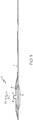
- FIG. 1 there is shown a multiple balloon type catheter (2) along whose main catheter shaft (7) is an expanded side balloon structure (5).
- FIG. 2 shows disposed about the inflated side balloon structure (5) and the inflated main catheter balloon (3) a bifurcated stent (1) in an expanded state.
- Some examples of multiple lumen catheters are discussed in published US Patent Publication Nos. US 2003/0163082 , US 2005/0015108A1 , and US 2005/0102019A1 .
- the multiple lumen type balloon catheter (2) comprises at least two balloons. One is the main catheter balloon (3) and the other is the side branch balloon (6).
- the side branch balloon (6) comprises a side balloon structure (5) in fluid communication with a side inflation lumen (8).
- single balloon type balloon catheters are discussed in published US Patent Publication No. US 2004/0138737 A1 .
- integrated into the material of the main catheter balloon is a blister or bulge which defines the side balloon structure (5).
- the stent (1) comprises two portions, a generally tubular main stent body (10) which defines a primary fluid lumen (14) and a side branch assembly (30).
- the stent (1) has an expanded and an unexpanded state. When in the expanded state, the stent (1) assumes a greater volume than when in the unexpanded state.
- the main stent body or main branch (10) of the bifurcated stent (1) extends about a main branch central axis (16).
- the main stent body (10) can be expanded by pressure applied to the inner surface of the main stent body (10) by the inflation of the main catheter balloon (3), it can be inflated by a self-expansion mechanism, or it can be expanded by some combination of the two.
- the side branch assembly or side branch (30) forms a bifurcating side branch which defines a secondary fluid lumen (34) in fluid communication with the primary fluid lumen (14).
- the side branch assembly extends about a side branch axis (46).
- This side branch is capable of extending in a radial direction (31) out of the parent vessel and into the branch vessel.
- the side branch assembly (30) comprises one or more petals (32).
- the definition of the term "petal” is one or more side branch members capable of twisting, bending, pivoting or otherwise opening to define the second fluid lumen (34) by opening away from the tubular shape defined by the generally tubular structure of the outer surface of the first stent body (10).
- side branch assemblies can also comprises non-petal structures. As a result, all embodiments in this application which describe petals will be understood to contemplate non-petal type side branch assemblies as well.
- the petals (32) can be arranged in an iris configuration when the stent (1) is unexpanded and in a crown configuration when the stent (1) is expanded.
- iris is when one or more petals (32) are generally lying along the tubular shape defined by the generally tubular structure of the outer surface of the first stent body (10) and are covering at least a portion of a side branch opening (18) in the main stent body (10).
- the definition of the term “crown” is when as at least one petal (32) are positioned at an oblique angle radially displaced from the tubular shape defined by the generally tubular structure of the outer surface of the first stent body (10).
- oblique is an angle of greater than zero degrees, such as an angle of between about 1 and about 180 degrees.
- An oblique angle explicitly includes angles of both exactly and about 90 degrees.
- the side balloon structure (5) Before expansion, when in the unexpanded state, the side balloon structure (5) is in an un-inflated configuration.
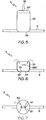
- this un-inflated configuration is the result of deflation and/or the application of a generally untargeted force in the luminal (towards the stent lumen) direction (35) or one or more generally untargeted forces along at least a portion of the radial end (60), the luminal end (59), and/or the side length (58) of the side balloon structure (5) (as shown in FIG. 3 ), the un-inflated balloon assumes an irregular shape.
- FIG. 4 illustrates, simple compressive force causes the balloon folds (57) and the overall assumed shape to be randomly formed due to the inconsistent and random buckling and pleating that takes place within the balloon material.
- the side balloon structure (5) when in the unexpanded state is configured according to an organized arrangement.
- FIG. 6 there is shown one such organized arrangement, the "cup" arrangement.
- the cup arrangement is characterized by a folded interface (56) being formed between the upper and lower ends of the side balloon structure.
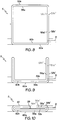
- FIG. 9 illustrates the cup arrangement in a dual lumen type balloon catheter and
- FIG. 12 illustrates the cup arrangement in a single lumen type balloon catheter not being part of the invention.
- the cup arrangement is formed by the application of a compressive force in the luminal direction (35) evenly distributed along the entirety of the radial end (60) and vectored towards the luminal end (59).
- This force can be applied in combination with a mandrel which keeps the side lengths (58) straight and rigid.
- This applied force will cause a folded interface to form between that portion of the side length (58) that is pushed internal to the inner side of the lower ends of the side lengths (58a') and that portion which remains external to the inner side of the lower ends of the side lengths (58a').
- a lip (29) forms.
- the cup arrangement is formed by the application of a luminally directed (35) force focused towards the center of the radial end (60) of the side balloon structure (5).
- This focused force cooperates with a side directed force that pushes that portion of the upper end of the balloon material internal to the inner side of the lower ends of the side lengths (58a') to be flush with the inner side of the lower ends of the side lengths (58a').
- the side balloon structure (5) can folded while, before, or after the main stent body inflating balloon or balloon portion is inflated or collapsed.
- FIG. 7 there is shown at least one embodiment of the invention where at least some of the upper ends of the side lengths (58a" and 58b") and lower ends of the side lengths (58a' and 58b') are folded according to a "discus" arrangement.
- the discus arrangement iscooperative with a cup arrangement.
- at least a portion of the outer surface of the upper end of the side length (58a") is folded in such a manner that it lies flush against the outer surface of the radial end (60b).
- the discus arrangement in the side balloon structure (5) has generally organized arrangement of pleats (40) in the folded balloon material. These pleats (40) can be evenly spaced about the compressed side balloon structure (5). Because those portions of the balloon material closer to the center of the side balloon structure (5) have less area for their material to be spread about, the pleats (40) are present in portions of the balloon material closer to the center of the side balloon structure (5). Referring now to FIGs 10 and 11 , it can be understood because the pleats allow for overlap of balloon material in the smaller central region of the side balloon structure (5) in the discus arrangement, they can be located at or near the lip (29) between the upper and lower ends of the side length of the side balloon structure (5).
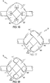
- FIGs. 14 and 15 at least a portion of the side balloon structure (5) is in a discus arrangement where the overlapping folds of material (27) are in an inter-layered arrangement.
- FIG. 14 illustrates a top down view of this structure and FIG. 15 delineates with phantom lines the covered folded segments of balloon material (20).
- inter-layered is defined as an arrangement in which one side of an object is positioned above the adjacent side of a first adjacent object and the other opposite side of the object is positioned below the adjacent side of a second adjacent object.
- each inter-layered segment radially pushes the adjacent segment reducing the overall energy needed to radially push all of the segments.
- the arrangements cause the segments to move in a rotational direction (43).
- This rotational direction (43) provides a precisely directed pushing force against the crowning side branch assembly, and by sweeping each of the petals in a different tangential direction, reduces the likelihood of petals colliding with each other when crowning.
- the phantom lines in FIG. 15 shown at least one embodiment where the overlapping regions (41) become progressively smaller the further they are from the center of the side balloon structure (5).
- FIG. 16 there are shown an embodiment in which the discus arrangement features a plurality of evenly spaced pleats (40).
- the evenly spaced pleats (40) when inflated at least partially push the petals in different direction reducing the likelihood of petal collisions.
- FIGs. 17 and 18 illustrate embodiments having combinations of the features of FIGs. 14 and 16.
- FIGs. 17 and 18 show both one or more pleats (40) and one or more folded overlapping regions (41).
- FIGs. 17 and 18 show that if one segment (20) of balloon material has a highly overlapping region at one end (45") it can also have a less overlapping region (45') at the other end of that segment. Modifying the degree of overlap at different segment ends allows for modulation in the rotational sweep and speed with which different portions of the side balloon structure (5) will attain during inflation. Such modulation facilitates expansion of irregularly shaped side branch structures.
- the various flush and even folding arrangements impart a number of advantages to the inflation process of the side balloon structure (5).
- One advantage is that the folding arrangement allows for control over the sequence of the inflation of particular portions of the side balloon structure allowing forces to be applied in a desired sequence.
- Another advantage is that they allow for the smooth and even expansion of the outer surface of the radial end (60b) as it moves radially (31) away from the luminal end (59).
- the organized unfolding that the side balloon undergoes has a predictable sweeping motion which is cooperative with the crowning motion of the petals.
- This predictable sweeping motion reduces or prevents shear forces which can be caused by erratic motion that accompanies the inflation induced smoothing out of erratically shaped fold lines and erratically positioned portions of the side balloon structure (5).
- the sweeping motion with which the organized folds and pleats unfold when expanded also reduces wasted inflation energy that would otherwise accompany untangling and untwisting erratically positioned portions of the side balloon structure (5).
- the organized folding designs are also repeatable and can be easily integrated into industrial production lines.
- the organized structures reduce the likelihood of unwanted volume producing voids occupying the side branch structure (5) reducing its overall profile.
- the flush and even folding arrangements when inflated allow for an increase in side balloon structure (5) volume at a uniform or predictable rate volume which reduces rapid fluctuations in the velocity of the balloon inflation which would otherwise accompany the inflation of dissimilarly folded portions.
- FIGs 19-23 illustrate one embodiment in which the precise pushing force is applied efficiently to petals (32), other portions of the side branch assembly (30), other portions of the balloon, or any other object positioned over the side balloon structure (5)
- FIGs. 19-23 there is shown at least one embodiment of a side balloon structure (5) having a cup and discus arrangement where the blunt unfocused radial force that the inflation of the side balloon structure (5) of FIG 4 would produce is replaced by an orderly, sequential, and precisely directed series of forces.
- the side balloon structure (5) inflates, first the discus arrangement at least partially unfolds, after which the cup arrangement is rearranged as the balloons volume is increased.
- the folded side balloon structure (5) prior to inflation, has a low cross sectional profile.
- FIG. 19 illustrates a volume void between the folded side lengths equal to the volume of the lengths it will be understood that significantly greater or lesser void volumes are contemplated by this invention.
- the radial bulge (36) is more luminal at its center than an its edges, the radial bulge (36) applies more pushing force against the petal summit (38) and less against the petal base (42) providing torque which is highly cooperative to the bending and twisting motion needed for successful crowning.
- the folding arrangement limits the allowed initial motions to the side lengths (58) in an outwardly directed arced path there is a greatly reduced the amount of friction, rubbing or chaffing between the petal and the unfolding side balloon structure (5).
- the petals (32) begin to bend outward (and away from majority of the mass of the side branch structure(5)) at the very beginning of the inflation process, the likelihood of an erratic motion by a portion of the balloon deforming, distorting, or otherwise improperly extending the side branch assembly becomes reduced.
- the petals develop outwardly directed momentum which reduces the overall energy needed to extend the petals (32).
- FIG. 22 there is shown that after the discus arrangement becomes somewhat unfolded the cup arrangement then becomes unfolded as well.
- the radially directed (31) force described in FIGs. 19, 20, and 21 declines and is replaced by outward a force directed in outward directions (37) parallel to axes extending from the center of the side opening (18) to the main stent body (10).
- This gradual replacement of the radially directed force with the outwardly directed force is complimentary to the direction vector of the petals as they gradually transition from a substantially iris configuration to a substantially crowned configuration.
- the petal tips (38) arc from a primarily radial trajectory (31 of FIG. 20 ) to a primarily outward trajectory (37) the sequence of inflation matches the motion of the petals resulting in highly efficient inflation system.
- the radial side (60) is thinner than (60) the side length (58).
- the thicker of the materials abuts the side branch assembly (30) reducing the likelihood that a portion of balloon will be ruptured or otherwise damaged by impacting against the side branch assembly (30).
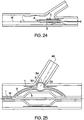
- FIGs. 24 and 25 there is shown the main catheter balloon (3) and the side balloon structure (5).
- the main catheter balloon (3) and the side balloon structure (5) are in fluid communication which allows the main catheter balloon (3) and the side balloon structure (5) to undergo common inflation and deflation.
- FIG. 24 illustrates a balloon catheter (2) in the unexpanded state and FIG. 25 in the expanded state. These figures also show inflation lumens at the distal and proximal sides of the side balloon structure (5) which can apply inflating fluid to different portions of the folded side balloon structure (5).
- Embodiments contemplated by this invention include catheters in which the main catheter balloon (3) and the side balloon structure (5) are linked to different fluid sources which allows them to undergo independent inflation and deflation.
- two or more inflation lumens can be positioned at locations about the side balloon structure (5). These inflation lumens need not only be distal to or proximal to the side balloon structure and can be positioned above, below, or at any position around the side balloon structure (5).
- the catheter may be configured so that each inflation lumen can be independently filled.
- the inflation lumens may be configured to be in common fluidic communication with one or more of the other inflation lumens.
- one or more inflation lumens may be independent to provide for the withdrawal of fluid from the side balloon structure (5) or may utilize valves to only allow fluid to pass once a desired pressure level is present within the side balloon structure (5) and/or within the inflation lumen.
- At least one of one or more fluid lumens are positioned directly against or immediately adjacent to one or more balloon portions including but not limited to: a lip, a folded segment, a pleat, a radial end, a luminal end, a side length, a inner side of a side length, an outer side of a side length, an upper end of a side of a side length, a lower end of a side length, or any combination thereof to facilitate its displacement prior to the displacement by inflation fluid of another second portion of the side balloon structure (5).
- Sequential displacement can be accomplished by the sequential flow of fluid through a number of specifically positioned lumens against specific side balloon structure portions.
- Such coordinated inflation can cause or cooperatively facilitate rotationally directed movement and momentum within the inflating side balloon structure (5).
- the stent, its delivery system, or other portion of an assembly may include one or more areas, bands, coatings, members, etc. that are detectable by imaging modalities such as X-Ray, MRI, ultrasound, etc.
- imaging modalities such as X-Ray, MRI, ultrasound, etc.
- at least a portion of the stent and/or adjacent assembly is at least partially radiopaque.
- At least a portion of the stent is configured to include one or more mechanisms for the delivery of a therapeutic agent.
- the agent will be in the form of a coating or other layer (or layers) of material placed on a surface region of the stent, which is adapted to be released at the site of the stent's implantation or areas adjacent thereto.
- the therapeutic agent can be at least one or various types of therapeutic agents including but not limited to: at least one restenosis inhibiting agent that comprises drug, polymer and bio-engineered materials or any combination thereof.
- the coating can be a therapeutic agent such as at least one drug, or at least one other pharmaceutical product such as non-genetic agents, genetic agents, cellular material, etc.
- suitable non-genetic therapeutic agents include but are not limited to: at least one anti-thrombogenic agents such as heparin, heparin derivatives, vascular cell growth promoters, growth factor inhibitors, Paclitaxel, etc.
- an agent includes a genetic therapeutic agent, such a genetic agent may include but is not limited to: DNA, RNA and their respective derivatives and/or components; hedgehog proteins, etc.
- the cellular material may include but is not limited to: cells of human origin and/or non-human origin as well as their respective components and/or derivatives thereof.
- the therapeutic agent includes a polymer agent
- the polymer agent may be a polystyrene-polyisobutylene- polystyrene triblock copolymer (SIBS), polyethylene oxide, silicone rubber and/or any other suitable substrate.
- SIBS polystyrene-polyisobutylene- polystyrene triblock copolymer
- silicone rubber any other suitable substrate.
Landscapes
- Health & Medical Sciences (AREA)
- Heart & Thoracic Surgery (AREA)
- Life Sciences & Earth Sciences (AREA)
- Engineering & Computer Science (AREA)
- Biomedical Technology (AREA)
- Animal Behavior & Ethology (AREA)
- Veterinary Medicine (AREA)
- Public Health (AREA)
- General Health & Medical Sciences (AREA)
- Pulmonology (AREA)
- Child & Adolescent Psychology (AREA)
- Biophysics (AREA)
- Anesthesiology (AREA)
- Hematology (AREA)
- Vascular Medicine (AREA)
- Transplantation (AREA)
- Oral & Maxillofacial Surgery (AREA)
- Cardiology (AREA)
- Prostheses (AREA)
- Media Introduction/Drainage Providing Device (AREA)
Abstract
Description
- In some embodiments this invention relates to implantable medical devices, their manufacture, and methods of use. Some embodiments are directed to delivery systems, such as catheter systems of all types, which are utilized in the delivery of such devices.
- Balloon catheters are employed in a variety of medical procedures. One such procedure is angioplasty which is a well known medical practice used in the treatment of diseased arteries hi the vasculature of a patient. Using angioplasty procedures, alone, however, involves a risk of restenosis of the artery, which may necessitate another angioplasty procedure, a surgical bypass procedure, or some method of repairing or strengthening the area. Therefore, it has become more common practice to use a catheter-delivered stent to prevent restenosis and to reinforce and strengthen weakened vessel walls.
- Catheter balloon systems and methods configured to deploy stents at a bifurcation in a body lumen are described in
US 2005/0102019 A1 . - A stent is a medical device introduced to a body lumen and is well known in the art. Stents, grafts, stent-grafts, vena cava filters, expandable frameworks, and similar implantable medical devices, collectively referred to hereinafter as stents, are radially expandable endoprostheses which are typically intravascular implants capable of being implanted transluminally and enlarged radially after being introduced percutaneously. Typically, a stent is implanted in a blood vessel at the site of a stenosis or aneurysm endoluminally, i.e. by so-called "minimal ly invasive techniques" in which the stent in a radially reduced configuration, optionally restrained in a radially compressed configuration by a sheath and/or catheter, is delivered by a stent delivery system or "introducer" to the site where it is required. The introducer may enter the body from an access location outside the body, such as through the patient's skin, or by a "cut down" technique in which the entry blood vessel is exposed by minor surgical means.
- After being introduced percutaneously, stents can be expanded by an internal radial force, such as when mounted on an inflatable balloon. Stents can also be self-expanding or a combination of self-expanding and balloon expandable (hybrid expandable). Stents may be implanted to prevent restenosis following angioplasty in the vascular system. Stents may be expanded and implanted in a variety of body lumens or vessels such as within the vascular system, urinary tracts, bile ducts, fallopian tubes, coronary vessels, secondary vessels, etc.
- A number of complications arise when stenoses form at vessel bifurcation sites. A bifurcation site is an area of the vasculature or other portion of the body where a first (or parent) vessel is bifurcated into two or more branch vessels. Where a stenotic lesion or lesions form at such a bifurcation, the lesion(s) can affect only one of the vessels (i.e., either of the branch vessels or the parent vessel) two of the vessels, or all three vessels. One complication involves irregular folding of the balloon or balloon portion which pushes against and moves that portion of the stent which expands into the vessel bifurcation. While auxiliary portions of a delivery system have been successful in expanding portions of stents into a side branch vessel, there remains a need for devices that are particularly suitable for expanding stents at a bifurcation to achieve an ideal expanded configuration.
- The art referred to and/or described above is not intended to constitute an admission that any patent, publication or other information referred to herein is "prior art" with respect to this invention.
US 2005/0102019 A1 discloses a catheter balloon system provided for treatment of a bifurcation of body lumen. A branch vessel balloon includes an accordion configuration capable of being expanded from an unexpanded collapsed accordion configuration to an expanded accordion configuration extending into a side branch vessel. - The problem of the invention is to provide a balloon catheter comprising side branch balloon assembly which aids for deployment of the side branch assembly of the stent.
- The problem is solved by a balloon catheter according to
claim 1. - Without limiting the scope of the invention a brief summary of some of the claimed embodiments of the invention is set forth below. Additional details of the summarized embodiments of the invention and/or additional embodiments of the invention may be found in the Detailed Description of the Invention below.
- This invention as claimed in
claim 1 contemplates a number of embodiments where any one, any combination of some, or all of the embodiments can be incorporated into a stent and/or a stent delivery system and/or a method of use. The present invention relates to novel folding arrangement for inflation balloons. The inflation balloons are folded in a systematic pattern which aids in the proper deployment of the side branch assembly of the stent. In particular, the improved folding arrangement aids in the deployment of the extending members relative to the bifurcated vessel wall. These and other aspects of the invention are set forth below. - At least one example of the invention is directed to a balloon catheter comprising a balloon inflation system. The balloon inflation system has a side branch balloon structure capable of at least partially expanding a side branch structure of a bifurcated stent. When in an un-inflated configuration, the side branch balloon structure is folded in a pattern which permits orderly unfolding when the side branch is inflated. Contemplated example include a main branch balloon structure capable of inflating a main tubular body of a bifurcated stent which is either in or not in fluid communication with the side branch balloon structure.
- At least one embodiment of the invention is directed to a side branch balloon structure comprising a radial end, a luminal end, and a side wall extending between the radial and luminal ends. When in the inflated configuration the radial end is further away from the main branch central axis than the luminal end and the luminal end is abutting a main catheter balloon. When in the un-inflated configuration, the side branch balloon structure is folded into a discus from a cup fold, where an inner surface of the radial end is flush with an inner surface of the luminal end, in a pleated or overlapping fold pattern. The side portion can also be folded such that: it is folded into three or more segments with overlapping regions between the folded segments, at least one segment lies above one overlapping region and beneath one overlapping region, every folded segment lies above one overlapping region and beneath one overlapping region, at least some of the overlapping folds are of different sizes, at least some of the pleats are of different sizes, and/or the pattern is generally uniform about a side branch axis.
- At least one embodiment of the invention is directed to a balloon catheter as claimed in
claim 1 further comprising a catheter shaft disposed about which is a bifurcated stent. The bifurcated stent has a main tubular body and a side branch structure having an iris and a crown configuration. When in the crown configuration at least a portion of the side branch assembly defines a fluid lumen in fluid communication with main tubular body and extends away from the main tubular body at an oblique angle. When in the iris configuration at least a portion of the side branch assembly is positioned adjacent to the orderly folded side branch balloon structure. The side branch assembly can also comprise one or more petals which when crowned define at least a portion of the second fluid lumen. The folded pattern results in the positioning of smooth portions of the side branch balloon structure against the petals. These smooth portions can be without folds and can cause a portion of the side branch balloon structure to inflate in a sweeping rotational motion. In addition, the pattern can allow for at least a portion of the side branch balloon structure to inflate by first primarily expanding in a circumferential direction away from a center of the side branch balloon structure and later primarily expanding in a radial direction. - At least one embodiment of the invention is directed to a method of folding a side branch balloon structure comprising the steps of: forming a cup by folding a radial end of the a side branch balloon structure into a luminal end of the side branch balloon structure and forming a discus by smoothly folding down the most radial portion of the cup against the radial end of the side branch balloon structure. The method can further including the steps of: inflating the side branch balloon, deflating the side branch balloon, and crimping an unexpanded side branch assembly of an unexpanded bifurcated stent over the folded side branch balloon structure.
- The invention is best understood from the following detailed description when read in connection with accompanying drawings, in which:
-
Figure 1 is a cross sectional perspective view of an inflated bifurcating balloon on a balloon catheter. -
Figure 2 is a schematic perspective view of an expanded bifurcated stent on a balloon catheter. -
Figure 3 is a cross sectional schematic view of a bifurcating balloon. -
Figure 4 is a cross sectional schematic view of a bifurcating balloon which is irregularly compressed. -
Figure 5 is a cross sectional schematic view of a bifurcating balloon being systematically folded. -
Figure 6 is a cross sectional schematic view of a bifurcating balloon systematically folded into a cup configuration. -
Figure 7 is an overhead view cross sectional schematic view of a systematically folded bifurcating balloon. -
Figure 8 is a cross sectional schematic view of an inflated bifurcating balloon in a dual lumen type inflation assembly. -
Figure 9 is a cross sectional schematic view of a bifurcating balloon in a dual lumen type inflation assembly systematically folded into a cup configuration. -
Figure 10 is a cross sectional schematic view of a bifurcating balloon in a dual lumen type inflation assembly systematically folded into a discus configuration. -
Figure 11 is a cross sectional schematic view of an inflated bifurcating balloon in a single lumen type inflation assembly. -
Figure 12 is a cross sectional schematic view of a bifurcating balloon in a single lumen type inflation assembly systematically folded into a cup configuration. -
Figure 13 is a cross sectional schematic view of a bifurcating balloon in a single lumen type inflation assembly systematically folded into a discus configuration. -
Figure 14 is a detailed overhead schematic view of a systematically folded bifurcating balloon. -
Figure 15 a detailed cross sectional overhead schematic view of a systematically folded bifurcating balloon. -
Figure 16 is a detailed overhead schematic view of a systematically pleated bifurcating balloon. -
Figure 17 is a detailed overhead schematic view of a systematically folded and pleated bifurcating balloon. -
Figure 18 is a detailed overhead cross sectional schematic view of a systematically folded and pleated bifurcating balloon. -
Figure 19 is a cross sectional schematic view of a systematically folded bifurcating balloon beneath a stent side branch assembly. -
Figure 20 is a cross sectional schematic view of a systematically folded bifurcating balloon beneath a stent side branch assembly with a bulging radial end. -
Figure 21 is a cross sectional schematic view of a systematically folded bifurcating balloon beneath a stent side branch assembly with a bulging radial end that is crowning the side branch assembly. -
Figure 22 is a cross sectional schematic view of a systematically folded bifurcating balloon which has reversed its cup configuration. -
Figure 23 is a cross sectional schematic view of an inflated systematically folded bifurcating balloon about which is disposed a crowned sent side branch assembly. -
Figure 24 is a cross sectional schematic view of an unexpanded bifurcating balloon catheter system positioned within a bifurcation site. -
Figure 25 is a cross sectional schematic view of an expanded bifurcating balloon catheter system which has deployed a stent within a bifurcation site. - The invention will next be illustrated with reference to the figures wherein the same numbers indicate similar elements in all figures. Such figures are intended to be illustrative rather than limiting and are included herewith to facilitate the explanation of the apparatus of the present invention.
- For the purposes of this disclosure, like reference numerals in the figures shall refer to like features unless otherwise indicated.
- Depicted in the figures are various aspects of the invention. Elements depicted in one figure may be combined with, or substituted for, elements depicted in another figure as desired.
- Embodiments of the invention are directed to folding arrangements of both multiple lumen type and single lumen type balloon catheters. Referring now to
FIG. 1 , there is shown a multiple balloon type catheter (2) along whose main catheter shaft (7) is an expanded side balloon structure (5).FIG. 2 shows disposed about the inflated side balloon structure (5) and the inflated main catheter balloon (3) a bifurcated stent (1) in an expanded state. Some examples of multiple lumen catheters are discussed in published US Patent Publication Nos.US 2003/0163082 ,US 2005/0015108A1 , andUS 2005/0102019A1 . The multiple lumen type balloon catheter (2) comprises at least two balloons. One is the main catheter balloon (3) and the other is the side branch balloon (6). The side branch balloon (6) comprises a side balloon structure (5) in fluid communication with a side inflation lumen (8). - Some examples of single balloon type balloon catheters are discussed in published US Patent Publication No.
US 2004/0138737 A1 . In a single balloon type balloon catheter, integrated into the material of the main catheter balloon is a blister or bulge which defines the side balloon structure (5). As the main catheter balloon is inflated, its side balloon structure (5) inflates as well. - Referring again to
FIG. 2 it is shown that the stent (1) comprises two portions, a generally tubular main stent body (10) which defines a primary fluid lumen (14) and a side branch assembly (30). The stent (1) has an expanded and an unexpanded state. When in the expanded state, the stent (1) assumes a greater volume than when in the unexpanded state. The main stent body or main branch (10) of the bifurcated stent (1) extends about a main branch central axis (16). The main stent body (10) can be expanded by pressure applied to the inner surface of the main stent body (10) by the inflation of the main catheter balloon (3), it can be inflated by a self-expansion mechanism, or it can be expanded by some combination of the two. - When the stent (1) is in the expanded state, the side branch assembly or side branch (30) forms a bifurcating side branch which defines a secondary fluid lumen (34) in fluid communication with the primary fluid lumen (14). The side branch assembly extends about a side branch axis (46). This side branch is capable of extending in a radial direction (31) out of the parent vessel and into the branch vessel. In at least one embodiment, the side branch assembly (30) comprises one or more petals (32). For purposes of this application the definition of the term "petal" is one or more side branch members capable of twisting, bending, pivoting or otherwise opening to define the second fluid lumen (34) by opening away from the tubular shape defined by the generally tubular structure of the outer surface of the first stent body (10). It will be appreciated by persons of ordinary skill in the art that side branch assemblies can also comprises non-petal structures. As a result, all embodiments in this application which describe petals will be understood to contemplate non-petal type side branch assemblies as well.
- The petals (32) can be arranged in an iris configuration when the stent (1) is unexpanded and in a crown configuration when the stent (1) is expanded. For purposes of this application the definition of the term "iris" is when one or more petals (32) are generally lying along the tubular shape defined by the generally tubular structure of the outer surface of the first stent body (10) and are covering at least a portion of a side branch opening (18) in the main stent body (10). For purposes of this application the definition of the term "crown" is when as at least one petal (32) are positioned at an oblique angle radially displaced from the tubular shape defined by the generally tubular structure of the outer surface of the first stent body (10). For the purposes of this application, the definition of the term "oblique" is an angle of greater than zero degrees, such as an angle of between about 1 and about 180 degrees. An oblique angle explicitly includes angles of both exactly and about 90 degrees. The petals (32) are pushed from the iris configuration into the crown configuration at least in part by pressure applied to the inner surface of the petals (32) by the inflation of the a side balloon structure (5).
- Before expansion, when in the unexpanded state, the side balloon structure (5) is in an un-inflated configuration. When this un-inflated configuration is the result of deflation and/or the application of a generally untargeted force in the luminal (towards the stent lumen) direction (35) or one or more generally untargeted forces along at least a portion of the radial end (60), the luminal end (59), and/or the side length (58) of the side balloon structure (5) (as shown in
FIG. 3 ), the un-inflated balloon assumes an irregular shape. AsFIG. 4 illustrates, simple compressive force causes the balloon folds (57) and the overall assumed shape to be randomly formed due to the inconsistent and random buckling and pleating that takes place within the balloon material. Only a small portion if any of the inner surface of the radial end (60a) and the inner surface of the luminal end (59a) of the side balloon structure (58) come into direct contact with each other and are separated by material from other portions of the side balloon structure. - In at least one embodiment of the invention, the side balloon structure (5) when in the unexpanded state is configured according to an organized arrangement. Referring now to
FIG. 6 there is shown one such organized arrangement, the "cup" arrangement. When the side balloon structure (5) is in the cup arrangement, at least a portion of the inner surface of the radial end (60a) and the inner surface of the luminal end (59) are substantially flush with one another. Similarly at least a portion of the inner side of the upper ends of the side lengths (58a") and the inner side of the lower ends of the side lengths (58a') are also substantially flush with one another. The cup arrangement is characterized by a folded interface (56) being formed between the upper and lower ends of the side balloon structure.FIG. 9 illustrates the cup arrangement in a dual lumen type balloon catheter andFIG. 12 illustrates the cup arrangement in a single lumen type balloon catheter not being part of the invention. - As illustrated in
FIG. 5 , in at least one embodiment, the cup arrangement is formed by the application of a compressive force in the luminal direction (35) evenly distributed along the entirety of the radial end (60) and vectored towards the luminal end (59). This force can be applied in combination with a mandrel which keeps the side lengths (58) straight and rigid. This applied force will cause a folded interface to form between that portion of the side length (58) that is pushed internal to the inner side of the lower ends of the side lengths (58a') and that portion which remains external to the inner side of the lower ends of the side lengths (58a'). As portions of the side length (58) are pushed internal to the inner side of the lower ends of the side lengths (58a'), a lip (29) forms. - In at least one embodiment the cup arrangement is formed by the application of a luminally directed (35) force focused towards the center of the radial end (60) of the side balloon structure (5). This focused force cooperates with a side directed force that pushes that portion of the upper end of the balloon material internal to the inner side of the lower ends of the side lengths (58a') to be flush with the inner side of the lower ends of the side lengths (58a'). The side balloon structure (5) can folded while, before, or after the main stent body inflating balloon or balloon portion is inflated or collapsed.
- Referring now to
FIG. 7 there is shown at least one embodiment of the invention where at least some of the upper ends of the side lengths (58a" and 58b") and lower ends of the side lengths (58a' and 58b') are folded according to a "discus" arrangement. The discus arrangement iscooperative with a cup arrangement. In a discus arrangement, at least a portion of the outer surface of the upper end of the side length (58a") is folded in such a manner that it lies flush against the outer surface of the radial end (60b). - In at least one embodiment illustrated in
FIG. 7 , the discus arrangement in the side balloon structure (5) has generally organized arrangement of pleats (40) in the folded balloon material. These pleats (40) can be evenly spaced about the compressed side balloon structure (5). Because those portions of the balloon material closer to the center of the side balloon structure (5) have less area for their material to be spread about, the pleats (40) are present in portions of the balloon material closer to the center of the side balloon structure (5). Referring now toFIGs 10 and11 , it can be understood because the pleats allow for overlap of balloon material in the smaller central region of the side balloon structure (5) in the discus arrangement, they can be located at or near the lip (29) between the upper and lower ends of the side length of the side balloon structure (5). - In at least one embodiment illustrated in
FIGs. 14 and 15 , at least a portion of the side balloon structure (5) is in a discus arrangement where the overlapping folds of material (27) are in an inter-layered arrangement.FIG. 14 illustrates a top down view of this structure andFIG. 15 delineates with phantom lines the covered folded segments of balloon material (20). For purposes of this application, the term inter-layered is defined as an arrangement in which one side of an object is positioned above the adjacent side of a first adjacent object and the other opposite side of the object is positioned below the adjacent side of a second adjacent object.FIGs. 14 and 15 illustrate a segment (20) of the compressed side balloon structure (5) where the portion of a first end (20a) in a first overlapping region (41') is positioned above the material of at least one adjacent folded segment (20') and a second end (20b) overlapping region (41') is positioned below the material of at least one adjacent folded segment (20"). The inter-layered arrangement provides at least two advantages. First during inflation as each segment is pushed in a radial direction, each inter-layered segment radially pushes the adjacent segment reducing the overall energy needed to radially push all of the segments. Secondly while inflating, the arrangements cause the segments to move in a rotational direction (43). This rotational direction (43) provides a precisely directed pushing force against the crowning side branch assembly, and by sweeping each of the petals in a different tangential direction, reduces the likelihood of petals colliding with each other when crowning. The phantom lines inFIG. 15 shown at least one embodiment where the overlapping regions (41) become progressively smaller the further they are from the center of the side balloon structure (5). - Referring now to
FIG. 16 there are shown an embodiment in which the discus arrangement features a plurality of evenly spaced pleats (40). The evenly spaced pleats (40) when inflated at least partially push the petals in different direction reducing the likelihood of petal collisions.FIGs. 17 and 18 illustrate embodiments having combinations of the features ofFIGs. 14 and16. FIGs. 17 and 18 show both one or more pleats (40) and one or more folded overlapping regions (41). In addition they show that if one segment (20) of balloon material has a highly overlapping region at one end (45") it can also have a less overlapping region (45') at the other end of that segment. Modifying the degree of overlap at different segment ends allows for modulation in the rotational sweep and speed with which different portions of the side balloon structure (5) will attain during inflation. Such modulation facilitates expansion of irregularly shaped side branch structures. - The various flush and even folding arrangements impart a number of advantages to the inflation process of the side balloon structure (5). One advantage is that the folding arrangement allows for control over the sequence of the inflation of particular portions of the side balloon structure allowing forces to be applied in a desired sequence. Another advantage is that they allow for the smooth and even expansion of the outer surface of the radial end (60b) as it moves radially (31) away from the luminal end (59). Also, the organized unfolding that the side balloon undergoes has a predictable sweeping motion which is cooperative with the crowning motion of the petals. This predictable sweeping motion reduces or prevents shear forces which can be caused by erratic motion that accompanies the inflation induced smoothing out of erratically shaped fold lines and erratically positioned portions of the side balloon structure (5). The sweeping motion with which the organized folds and pleats unfold when expanded also reduces wasted inflation energy that would otherwise accompany untangling and untwisting erratically positioned portions of the side balloon structure (5). The organized folding designs are also repeatable and can be easily integrated into industrial production lines. In addition, the organized structures reduce the likelihood of unwanted volume producing voids occupying the side branch structure (5) reducing its overall profile. Similarly, the flush and even folding arrangements when inflated allow for an increase in side balloon structure (5) volume at a uniform or predictable rate volume which reduces rapid fluctuations in the velocity of the balloon inflation which would otherwise accompany the inflation of dissimilarly folded portions.
- The organized arrangement also allows for application of precise pushing force to be applied by the outer surface of the radial end (60b) against the petals. This precise pushing force increases inflation efficiency by assuring that majority of the volumetric expansion can be harnessed to crown the side branch assembly.
FIGs 19-23 illustrate one embodiment in which the precise pushing force is applied efficiently to petals (32), other portions of the side branch assembly (30), other portions of the balloon, or any other object positioned over the side balloon structure (5) - In
FIGs. 19-23 there is shown at least one embodiment of a side balloon structure (5) having a cup and discus arrangement where the blunt unfocused radial force that the inflation of the side balloon structure (5) ofFIG 4 would produce is replaced by an orderly, sequential, and precisely directed series of forces. When the side balloon structure (5) inflates, first the discus arrangement at least partially unfolds, after which the cup arrangement is rearranged as the balloons volume is increased. As shown inFIG. 19 , prior to inflation, the folded side balloon structure (5) has a low cross sectional profile. AlthoughFIG. 19 illustrates a volume void between the folded side lengths equal to the volume of the lengths it will be understood that significantly greater or lesser void volumes are contemplated by this invention. - As illustrated in
FIGs. 20 and temporally subsequentFIG. 21 , when the side balloon structure (5) begins its inflation, the outer surface of the radial end (60b) bulges radially before other portions of the side balloon structure (5). As shown inFIGs. 21 and 22 , this initial bulging applies a controlled radially directed pressing force against the folded side lengths (58). The radially directed pressure pushes the side lengths in a sweeping path complimentary to the bending or twisting motions that the petals (32) will undergo as they transition from an iris to a crown configuration. In particular, because the radial bulge (36) is more luminal at its center than an its edges, the radial bulge (36) applies more pushing force against the petal summit (38) and less against the petal base (42) providing torque which is highly cooperative to the bending and twisting motion needed for successful crowning. - Because the folding arrangement, limits the allowed initial motions to the side lengths (58) in an outwardly directed arced path there is a greatly reduced the amount of friction, rubbing or chaffing between the petal and the unfolding side balloon structure (5). In addition, because the petals (32) begin to bend outward (and away from majority of the mass of the side branch structure(5)) at the very beginning of the inflation process, the likelihood of an erratic motion by a portion of the balloon deforming, distorting, or otherwise improperly extending the side branch assembly becomes reduced. Lastly because the initial inflation process moves the petals, the petals develop outwardly directed momentum which reduces the overall energy needed to extend the petals (32).
- Referring now to
FIG. 22 there is shown that after the discus arrangement becomes somewhat unfolded the cup arrangement then becomes unfolded as well. The radially directed (31) force described inFIGs. 19, 20, and 21 declines and is replaced by outward a force directed in outward directions (37) parallel to axes extending from the center of the side opening (18) to the main stent body (10). This gradual replacement of the radially directed force with the outwardly directed force is complimentary to the direction vector of the petals as they gradually transition from a substantially iris configuration to a substantially crowned configuration. Because as the petals become more crowned the petal tips (38) arc from a primarily radial trajectory (31 ofFIG. 20 ) to a primarily outward trajectory (37) the sequence of inflation matches the motion of the petals resulting in highly efficient inflation system. - Referring now to
FIG. 19 , in at least one embodiment, to facilitate the inflation properties of the side balloon structure (5), the radial side (60) is thinner than (60) the side length (58). By folding the side balloon structure (60) into discus arrangements, the thicker of the materials abuts the side branch assembly (30) reducing the likelihood that a portion of balloon will be ruptured or otherwise damaged by impacting against the side branch assembly (30). - Referring now to
FIGs. 24 and 25 there is shown the main catheter balloon (3) and the side balloon structure (5). The main catheter balloon (3) and the side balloon structure (5) are in fluid communication which allows the main catheter balloon (3) and the side balloon structure (5) to undergo common inflation and deflation.FIG. 24 illustrates a balloon catheter (2) in the unexpanded state andFIG. 25 in the expanded state. These figures also show inflation lumens at the distal and proximal sides of the side balloon structure (5) which can apply inflating fluid to different portions of the folded side balloon structure (5). - Embodiments contemplated by this invention include catheters in which the main catheter balloon (3) and the side balloon structure (5) are linked to different fluid sources which allows them to undergo independent inflation and deflation. Similarly two or more inflation lumens can be positioned at locations about the side balloon structure (5). These inflation lumens need not only be distal to or proximal to the side balloon structure and can be positioned above, below, or at any position around the side balloon structure (5). Depending on the desired sequences of inflation, the catheter may be configured so that each inflation lumen can be independently filled. Alternatively the inflation lumens may be configured to be in common fluidic communication with one or more of the other inflation lumens. In addition one or more inflation lumens may be independent to provide for the withdrawal of fluid from the side balloon structure (5) or may utilize valves to only allow fluid to pass once a desired pressure level is present within the side balloon structure (5) and/or within the inflation lumen.
- Coordination of the order of inflation, inflation pressure, fluid flux, and fluid flow directions can be combined with the other inflation embodiments disclosed in this application to facilitate the efficient and successful inflation of the side balloon structure (5). In at least one embodiment, at least one of one or more fluid lumens are positioned directly against or immediately adjacent to one or more balloon portions including but not limited to: a lip, a folded segment, a pleat, a radial end, a luminal end, a side length, a inner side of a side length, an outer side of a side length, an upper end of a side of a side length, a lower end of a side length, or any combination thereof to facilitate its displacement prior to the displacement by inflation fluid of another second portion of the side balloon structure (5). Sequential displacement can be accomplished by the sequential flow of fluid through a number of specifically positioned lumens against specific side balloon structure portions. Such coordinated inflation can cause or cooperatively facilitate rotationally directed movement and momentum within the inflating side balloon structure (5).
- In some embodiments the stent, its delivery system, or other portion of an assembly may include one or more areas, bands, coatings, members, etc. that are detectable by imaging modalities such as X-Ray, MRI, ultrasound, etc. In some embodiments at least a portion of the stent and/or adjacent assembly is at least partially radiopaque.
- In some embodiments at least a portion of the stent is configured to include one or more mechanisms for the delivery of a therapeutic agent. Often the agent will be in the form of a coating or other layer (or layers) of material placed on a surface region of the stent, which is adapted to be released at the site of the stent's implantation or areas adjacent thereto.
- The therapeutic agent can be at least one or various types of therapeutic agents including but not limited to: at least one restenosis inhibiting agent that comprises drug, polymer and bio-engineered materials or any combination thereof. In addition, the coating can be a therapeutic agent such as at least one drug, or at least one other pharmaceutical product such as non-genetic agents, genetic agents, cellular material, etc. Some examples of suitable non-genetic therapeutic agents include but are not limited to: at least one anti-thrombogenic agents such as heparin, heparin derivatives, vascular cell growth promoters, growth factor inhibitors, Paclitaxel, etc. Where an agent includes a genetic therapeutic agent, such a genetic agent may include but is not limited to: DNA, RNA and their respective derivatives and/or components; hedgehog proteins, etc. Where a therapeutic agent includes cellular material, the cellular material may include but is not limited to: cells of human origin and/or non-human origin as well as their respective components and/or derivatives thereof. Where the therapeutic agent includes a polymer agent, the polymer agent may be a polystyrene-polyisobutylene- polystyrene triblock copolymer (SIBS), polyethylene oxide, silicone rubber and/or any other suitable substrate. It will be appreciated that other types of coating substances, well known to those skilled in the art, can be applied to the stent (1) as well.
- This completes the description of the preferred and alternate embodiments of the invention. The above disclosure is intended to be illustrative and not exhaustive. This description will suggest many variations and alternatives to one of ordinary skill in this art. The various elements shown in the individual figures and described above may be combined, substituted, or modified for combination as desired.
Claims (14)
- A balloon catheter comprising a balloon inflation system, the balloon inflation system comprising a side branch balloon structure, capable of at least partially expanding a side branch structure of a bifurcated stent, wherein:• the side branch balloon structure (5) has an inflated configuration having a radial end (60), a luminal end (59) and a side wall (39) there between, where the radial end (60) is further away from a main branch central axis than the luminal end (59) and the luminal end (59) is abutting a main catheter balloon (3) and• an un-inflated configuration,• characterised in that in the un-inflated configuration the side branch balloon structure is folded into a discus from a cup fold, where an inner surface of the radial end (60) is flush with an inner surface (59a) of the luminal end (59), in a pleated or overlapping fold pattern which permits orderly unfolding when the side branch is inflated.
- The balloon catheter of claim 1 further comprising a main branch balloon structure capable of inflating a main tubular body of said bifurcated stent wherein:the side branch balloon structure and the main branch balloon structure are in fluid communication with each other.
- The balloon catheter of claim 1 further comprising a main branch balloon structure capable of inflating a main tubular body of said bifurcated stent wherein:the side branch balloon structure and the main branch balloon structure are not in fluid communication with each other.
- The balloon catheter of claim 1 wherein in the un-inflated configuration, the side branch balloon structure is folded such that at least some of the side portion lies flush against and over the radial end.
- The balloon catheter of claim 4 wherein at least some of the side portion is folded in into pleats.
- The balloon catheter of claim 4 wherein at least some of the side portion is folded in into overlapping folds.
- The balloon catheter of claim 4 wherein the side portion is folded into three or more segments with overlapping regions between the folded segments, at least one segment lies above one overlapping region and beneath one overlapping region.
- The balloon catheter of claim 7 wherein every folded segment lies above one overlapping region and beneath one overlapping region.
- The balloon catheter of claim 1 further comprising a stent and a catheter shaft, the stent comprises a main tubular body and a side branch structure having an iris and a crown configuration,• the stent is disposed about the catheter shaft,• when in the crown configuration at least a portion of the side branch assembly defines a fluid lumen in fluid communication with main tubular body and extends away from the main tubular body at an oblique angle,• when in the iris configuration at least a portion of the side branch assembly is positioned adjacent to the orderly folded side branch balloon structure.
- The balloon catheter of claim 9 in which the side branch assembly comprises one or more petals which when crowned define at least a portion of the second fluid lumen, the orderly folded pattern having smooth portions of the side branch balloon structure lying against the petals.
- The balloon catheter of claim 10 in which the smooth portions of the side branch balloon structure lie flush against the petals.
- The balloon catheter of claim 1 in which the folded pattern allows for at least a portion of the side branch balloon structure to inflate in a sweeping rotational motion.
- The balloon catheter system of claim 1 in which the folded pattern allows for at least a portion of the side branch balloon structure to inflate by first primarily expanding in a circumferential direction away from a center of the side branch balloon structure and later primarily expanding in a radial direction.
- A method of folding a side branch balloon structure comprising the steps of:• forming a cup by folding a radial end of the a side branch balloon structure into a luminal end of the side branch balloon structure;• forming a discus by smoothly folding down the most radial portion of the cup against the radial end of the side branch balloon structure.
Applications Claiming Priority (2)
| Application Number | Priority Date | Filing Date | Title |
|---|---|---|---|
| US11/693,957 US8647376B2 (en) | 2007-03-30 | 2007-03-30 | Balloon fold design for deployment of bifurcated stent petal architecture |
| PCT/US2008/058401 WO2008121698A2 (en) | 2007-03-30 | 2008-03-27 | Balloon fold design for deployment of bifurcated stent petal architecture |
Publications (2)
| Publication Number | Publication Date |
|---|---|
| EP2134404A2 EP2134404A2 (en) | 2009-12-23 |
| EP2134404B1 true EP2134404B1 (en) | 2012-04-18 |
Family
ID=39795700
Family Applications (1)
| Application Number | Title | Priority Date | Filing Date |
|---|---|---|---|
| EP08744445A Not-in-force EP2134404B1 (en) | 2007-03-30 | 2008-03-27 | Balloon fold design for deployment of bifurcated stent petal architecture |
Country Status (6)
| Country | Link |
|---|---|
| US (1) | US8647376B2 (en) |
| EP (1) | EP2134404B1 (en) |
| JP (1) | JP5113240B2 (en) |
| AT (1) | ATE553808T1 (en) |
| CA (1) | CA2682463A1 (en) |
| WO (1) | WO2008121698A2 (en) |
Families Citing this family (16)
| Publication number | Priority date | Publication date | Assignee | Title |
|---|---|---|---|---|
| US8936567B2 (en) * | 2007-11-14 | 2015-01-20 | Boston Scientific Scimed, Inc. | Balloon bifurcated lumen treatment |
| EP2300093B1 (en) * | 2008-06-05 | 2016-04-20 | Boston Scientific Scimed, Inc. | Deflatable bifurcated device |
| US20090326643A1 (en) * | 2008-06-27 | 2009-12-31 | Boston Scientific Scimed, Inc. | Balloon folding apparatus and method |
| WO2010096570A2 (en) * | 2009-02-23 | 2010-08-26 | John To | Stent strut appositioner |
| EP2629715B1 (en) * | 2010-10-18 | 2016-01-06 | Apollo Endosurgery, Inc. | Reactive intragastric implant devices |
| US8870966B2 (en) | 2010-10-18 | 2014-10-28 | Apollo Endosurgery, Inc. | Intragastric balloon for treating obesity |
| EP4049625A1 (en) | 2011-12-09 | 2022-08-31 | Edwards Lifesciences Corporation | Prosthetic heart valve having improved commissure supports |
| EP3270997B1 (en) | 2015-03-19 | 2019-07-03 | Prytime Medical Devices, Inc. | System for low-profile occlusion balloon catheter |
| JP6408176B2 (en) | 2016-06-02 | 2018-10-17 | プリタイム・メディカル・デバイシーズ・インコーポレイテッドPrytime Medical Devices,Inc. | System and method for low profile occlusion balloon catheter |
| JP2018038682A (en) * | 2016-09-08 | 2018-03-15 | テルモ株式会社 | Stent delivery system |
| CA3049539C (en) | 2017-01-12 | 2022-09-20 | The Regents Of The University Of California | Endovascular perfusion augmentation for critical care |
| CN110769749B (en) | 2017-04-21 | 2023-05-09 | 加利福尼亚大学董事会 | Aortic flowmeter and pump for partial aortic occlusion |
| EP3473214A1 (en) * | 2017-10-18 | 2019-04-24 | Biotronik AG | Balloon catheter-stent device |
| ES2956788T3 (en) * | 2018-05-02 | 2023-12-28 | Meril Life Sciences Pvt Ltd | Pleating and folding process for a drug-coated balloon |
| EP3833273A4 (en) | 2018-08-06 | 2022-06-29 | Prytime Medical Devices, Inc. | System and method for low profile occlusion balloon catheter |
| AU2021239935A1 (en) | 2020-03-16 | 2022-10-06 | Certus Critical Care, Inc. | Blood flow control devices, systems, and methods and error detection thereof |
Family Cites Families (209)
| Publication number | Priority date | Publication date | Assignee | Title |
|---|---|---|---|---|
| US3643268A (en) * | 1970-09-30 | 1972-02-22 | Paul Stamberger | Self-inflatable hollow bodies for use as cushions and for like purposes |
| US4309994A (en) | 1980-02-25 | 1982-01-12 | Grunwald Ronald P | Cardiovascular cannula |
| US4774949A (en) | 1983-06-14 | 1988-10-04 | Fogarty Thomas J | Deflector guiding catheter |
| DE8717643U1 (en) | 1987-05-12 | 1989-09-21 | Domschke, Wolfram, Prof. Dr.med., 8520 Erlangen | Device for endoscopic-transpapillary probing of a bile duct system |
| US4935190A (en) | 1987-07-10 | 1990-06-19 | William G. Whitney | Method of making balloon retention catheter |
| US4769005A (en) | 1987-08-06 | 1988-09-06 | Robert Ginsburg | Selective catheter guide |
| US4896670A (en) | 1988-04-19 | 1990-01-30 | C. R. Bard, Inc. | Kissing balloon catheter |
| US4906244A (en) | 1988-10-04 | 1990-03-06 | Cordis Corporation | Balloons for medical devices and fabrication thereof |
| US5087246A (en) | 1988-12-29 | 1992-02-11 | C. R. Bard, Inc. | Dilation catheter with fluted balloon |
| US5147302A (en) | 1989-04-21 | 1992-09-15 | Scimed Life Systems, Inc. | Method of shaping a balloon of a balloon catheter |
| US4994071A (en) | 1989-05-22 | 1991-02-19 | Cordis Corporation | Bifurcating stent apparatus and method |
| US5037392A (en) | 1989-06-06 | 1991-08-06 | Cordis Corporation | Stent-implanting balloon assembly |
| US5318587A (en) | 1989-08-25 | 1994-06-07 | C. R. Bard, Inc. | Pleated balloon dilatation catheter and method of use |
| US5147385A (en) | 1989-11-01 | 1992-09-15 | Schneider (Europe) A.G. | Stent and catheter for the introduction of the stent |
| US5053007A (en) | 1989-12-14 | 1991-10-01 | Scimed Life Systems, Inc. | Compression balloon protector for a balloon dilatation catheter and method of use thereof |
| US5163989A (en) | 1990-08-27 | 1992-11-17 | Advanced Cardiovascular Systems, Inc. | Method for forming a balloon mold and the use of such mold |
| AR246020A1 (en) | 1990-10-03 | 1994-03-30 | Hector Daniel Barone Juan Carl | A ball device for implanting an intraluminous aortic prosthesis, for repairing aneurysms. |
| DE59105247D1 (en) | 1990-10-04 | 1995-05-24 | Schneider Europ Ag | Balloon dilatation catheter. |
| EP0556309B1 (en) | 1990-11-09 | 1999-04-07 | Boston Scientific Corporation | Balloon for medical catheter |
| US5628783A (en) | 1991-04-11 | 1997-05-13 | Endovascular Technologies, Inc. | Bifurcated multicapsule intraluminal grafting system and method |
| US5304220A (en) | 1991-07-03 | 1994-04-19 | Maginot Thomas J | Method and apparatus for implanting a graft prosthesis in the body of a patient |
| FR2678508B1 (en) | 1991-07-04 | 1998-01-30 | Celsa Lg | DEVICE FOR REINFORCING VESSELS OF THE HUMAN BODY. |
| US5234727A (en) * | 1991-07-19 | 1993-08-10 | Charles Hoberman | Curved pleated sheet structures |
| US5693084A (en) | 1991-10-25 | 1997-12-02 | Cook Incorporated | Expandable transluminal graft prosthesis for repair of aneurysm |
| US5387235A (en) | 1991-10-25 | 1995-02-07 | Cook Incorporated | Expandable transluminal graft prosthesis for repair of aneurysm |
| US5226887A (en) | 1992-02-07 | 1993-07-13 | Interventional Technologies, Inc. | Collapsible folding angioplasty balloon |
| US5209799A (en) | 1992-04-17 | 1993-05-11 | Inverventional Technologies, Inc. | Method for manufacturing a folding balloon catheter |
| US5342387A (en) | 1992-06-18 | 1994-08-30 | American Biomed, Inc. | Artificial support for a blood vessel |
| US5487730A (en) | 1992-12-30 | 1996-01-30 | Medtronic, Inc. | Balloon catheter with balloon surface retention means |
| IL106738A (en) | 1993-08-19 | 1998-02-08 | Mind E M S G Ltd | Device for external correction of deficient valves in venous junctions |
| US5746745A (en) * | 1993-08-23 | 1998-05-05 | Boston Scientific Corporation | Balloon catheter |
| US5639278A (en) | 1993-10-21 | 1997-06-17 | Corvita Corporation | Expandable supportive bifurcated endoluminal grafts |
| US5632772A (en) | 1993-10-21 | 1997-05-27 | Corvita Corporation | Expandable supportive branched endoluminal grafts |
| US5350361A (en) | 1993-11-10 | 1994-09-27 | Medtronic, Inc. | Tri-fold balloon for dilatation catheter and related method |
| US5607444A (en) | 1993-12-02 | 1997-03-04 | Advanced Cardiovascular Systems, Inc. | Ostial stent for bifurcations |
| US5609627A (en) | 1994-02-09 | 1997-03-11 | Boston Scientific Technology, Inc. | Method for delivering a bifurcated endoluminal prosthesis |
| US5456666A (en) | 1994-04-26 | 1995-10-10 | Boston Scientific Corp | Medical balloon folding into predetermined shapes and method |
| US5683451A (en) | 1994-06-08 | 1997-11-04 | Cardiovascular Concepts, Inc. | Apparatus and methods for deployment release of intraluminal prostheses |
| US5458572A (en) | 1994-07-01 | 1995-10-17 | Boston Scientific Corp. | Catheter with balloon folding into predetermined configurations and method of manufacture |
| US5636641A (en) | 1994-07-25 | 1997-06-10 | Advanced Cardiovascular Systems, Inc. | High strength member for intracorporeal use |
| US5609605A (en) | 1994-08-25 | 1997-03-11 | Ethicon, Inc. | Combination arterial stent |
| CA2134997C (en) | 1994-11-03 | 2009-06-02 | Ian M. Penn | Stent |
| CA2175720C (en) | 1996-05-03 | 2011-11-29 | Ian M. Penn | Bifurcated stent and method for the manufacture and delivery of same |
| US5613980A (en) | 1994-12-22 | 1997-03-25 | Chauhan; Tusharsindhu C. | Bifurcated catheter system and method |
| NL9500094A (en) | 1995-01-19 | 1996-09-02 | Industrial Res Bv | Y-shaped stent and method of deployment. |
| US7204848B1 (en) | 1995-03-01 | 2007-04-17 | Boston Scientific Scimed, Inc. | Longitudinally flexible expandable stent |
| US5709713A (en) | 1995-03-31 | 1998-01-20 | Cardiovascular Concepts, Inc. | Radially expansible vascular prosthesis having reversible and other locking structures |
| FR2733682B1 (en) * | 1995-05-04 | 1997-10-31 | Dibie Alain | ENDOPROSTHESIS FOR THE TREATMENT OF STENOSIS ON BIFURCATIONS OF BLOOD VESSELS AND LAYING EQUIPMENT THEREFOR |
| US5591228A (en) | 1995-05-09 | 1997-01-07 | Edoga; John K. | Methods for treating abdominal aortic aneurysms |
| US5833657A (en) | 1995-05-30 | 1998-11-10 | Ethicon, Inc. | Single-walled balloon catheter with non-linear compliance characteristic |
| US5707348A (en) | 1995-06-06 | 1998-01-13 | Krogh; Steve S. | Intravenous bandage |
| IL122202A0 (en) | 1995-06-08 | 1998-04-05 | Bard Galway Ltd | Bifurcated endovascular stent |
| EP0753399A1 (en) * | 1995-07-10 | 1997-01-15 | ANCAN S.r.l. | Method for folding plane surfaces |
| FR2737969B1 (en) | 1995-08-24 | 1998-01-30 | Rieu Regis | INTRALUMINAL ENDOPROSTHESIS IN PARTICULAR FOR ANGIOPLASTY |
| US5824036A (en) | 1995-09-29 | 1998-10-20 | Datascope Corp | Stent for intraluminal grafts and device and methods for delivering and assembling same |
| US5669924A (en) | 1995-10-26 | 1997-09-23 | Shaknovich; Alexander | Y-shuttle stent assembly for bifurcating vessels and method of using the same |
| FR2740346A1 (en) | 1995-10-30 | 1997-04-30 | Debiotech Sa | ANGIOPLASTY DEVICE FOR ARTERIAL BIFURCATION |
| US5632762A (en) | 1995-11-09 | 1997-05-27 | Hemodynamics, Inc. | Ostial stent balloon |
| US5824040A (en) | 1995-12-01 | 1998-10-20 | Medtronic, Inc. | Endoluminal prostheses and therapies for highly variable body lumens |
| US5882334A (en) | 1995-12-04 | 1999-03-16 | Target Therapeutics, Inc. | Balloon/delivery catheter assembly with adjustable balloon positioning |
| US6017363A (en) | 1997-09-22 | 2000-01-25 | Cordis Corporation | Bifurcated axially flexible stent |
| US6436104B2 (en) | 1996-01-26 | 2002-08-20 | Cordis Corporation | Bifurcated axially flexible stent |
| US6258116B1 (en) | 1996-01-26 | 2001-07-10 | Cordis Corporation | Bifurcated axially flexible stent |
| US6071285A (en) | 1996-03-25 | 2000-06-06 | Lashinski; Robert D. | Rapid exchange folded balloon catheter and stent delivery system |
| US5824042A (en) | 1996-04-05 | 1998-10-20 | Medtronic, Inc. | Endoluminal prostheses having position indicating markers |
| BE1010183A3 (en) | 1996-04-25 | 1998-02-03 | Dereume Jean Pierre Georges Em | Luminal endoprosthesis FOR BRANCHING CHANNELS OF A HUMAN OR ANIMAL BODY AND MANUFACTURING METHOD THEREOF. |
| UA58485C2 (en) | 1996-05-03 | 2003-08-15 | Медінол Лтд. | Method for manufacture of bifurcated stent (variants) and bifurcated stent (variants) |
| US6440165B1 (en) | 1996-05-03 | 2002-08-27 | Medinol, Ltd. | Bifurcated stent with improved side branch aperture and method of making same |
| US6251133B1 (en) | 1996-05-03 | 2001-06-26 | Medinol Ltd. | Bifurcated stent with improved side branch aperture and method of making same |
| US6770092B2 (en) | 1996-05-03 | 2004-08-03 | Medinol Ltd. | Method of delivering a bifurcated stent |
| US5851464A (en) | 1996-05-13 | 1998-12-22 | Cordis Corporation | Method of making a fuseless soft tip catheter |
| US5718684A (en) | 1996-05-24 | 1998-02-17 | Gupta; Mukesh | Multi-lobed balloon catheter |
| US5669932A (en) | 1996-05-29 | 1997-09-23 | Isostent, Inc. | Means for accurately positioning an expandable stent |
| US5617878A (en) | 1996-05-31 | 1997-04-08 | Taheri; Syde A. | Stent and method for treatment of aortic occlusive disease |
| BR9702255A (en) | 1996-05-31 | 1999-02-17 | Bard Galway Ltd | Bifurcated endovascular extenders and methods and apparatus for placing them |
| US5755773A (en) | 1996-06-04 | 1998-05-26 | Medtronic, Inc. | Endoluminal prosthetic bifurcation shunt |
| US8728143B2 (en) | 1996-06-06 | 2014-05-20 | Biosensors International Group, Ltd. | Endoprosthesis deployment system for treating vascular bifurcations |
| US7238197B2 (en) | 2000-05-30 | 2007-07-03 | Devax, Inc. | Endoprosthesis deployment system for treating vascular bifurcations |
| FR2749500B1 (en) | 1996-06-06 | 1998-11-20 | Jacques Seguin | DEVICE ALLOWING THE TREATMENT OF BODY DUCTS AT THE LEVEL OF A BIFURCATION |
| US5697971A (en) | 1996-06-11 | 1997-12-16 | Fischell; Robert E. | Multi-cell stent with cells having differing characteristics |
| US5676697A (en) | 1996-07-29 | 1997-10-14 | Cardiovascular Dynamics, Inc. | Two-piece, bifurcated intraluminal graft for repair of aneurysm |
| US5749825A (en) | 1996-09-18 | 1998-05-12 | Isostent, Inc. | Means method for treatment of stenosed arterial bifurcations |
| US5755778A (en) | 1996-10-16 | 1998-05-26 | Nitinol Medical Technologies, Inc. | Anastomosis device |
| US6599316B2 (en) | 1996-11-04 | 2003-07-29 | Advanced Stent Technologies, Inc. | Extendible stent apparatus |
| US6692483B2 (en) | 1996-11-04 | 2004-02-17 | Advanced Stent Technologies, Inc. | Catheter with attached flexible side sheath |
| US7591846B2 (en) | 1996-11-04 | 2009-09-22 | Boston Scientific Scimed, Inc. | Methods for deploying stents in bifurcations |
| US6835203B1 (en) | 1996-11-04 | 2004-12-28 | Advanced Stent Technologies, Inc. | Extendible stent apparatus |
| US6325826B1 (en) | 1998-01-14 | 2001-12-04 | Advanced Stent Technologies, Inc. | Extendible stent apparatus |
| US7220275B2 (en) | 1996-11-04 | 2007-05-22 | Advanced Stent Technologies, Inc. | Stent with protruding branch portion for bifurcated vessels |
| US7341598B2 (en) | 1999-01-13 | 2008-03-11 | Boston Scientific Scimed, Inc. | Stent with protruding branch portion for bifurcated vessels |
| US6596020B2 (en) | 1996-11-04 | 2003-07-22 | Advanced Stent Technologies, Inc. | Method of delivering a stent with a side opening |
| EP0944366B1 (en) | 1996-11-04 | 2006-09-13 | Advanced Stent Technologies, Inc. | Extendible double stent |
| US5972017A (en) | 1997-04-23 | 1999-10-26 | Vascular Science Inc. | Method of installing tubular medical graft connectors |
| FR2756173B1 (en) | 1996-11-22 | 1999-02-12 | Marcade Jean Paul | MODULAR AND EXPANDABLE ENDOPROSTHESIS FOR THE ARTERIAL NETWORK |
| US5749890A (en) | 1996-12-03 | 1998-05-12 | Shaknovich; Alexander | Method and system for stent placement in ostial lesions |
| DE29701758U1 (en) | 1997-02-01 | 1997-03-27 | Jomed Implantate GmbH, 72414 Rangendingen | Radially expandable stent for implantation in a body vessel, particularly in the area of a vascular branch |
| DE29701883U1 (en) | 1997-02-04 | 1997-03-27 | Beck, Harry, 71732 Tamm | Central lubrication |
| US5720735A (en) | 1997-02-12 | 1998-02-24 | Dorros; Gerald | Bifurcated endovascular catheter |
| GB2322337B (en) * | 1997-02-20 | 2001-03-14 | Autoliv Dev | Improvements in or relating to a method of folding an air-bag |
| US6096073A (en) | 1997-02-25 | 2000-08-01 | Scimed Life Systems, Inc. | Method of deploying a stent at a lesion site located at a bifurcation in a parent vessel |
| US20020133222A1 (en) | 1997-03-05 | 2002-09-19 | Das Gladwin S. | Expandable stent having a plurality of interconnected expansion modules |
| JP4083241B2 (en) | 1997-04-23 | 2008-04-30 | アーテミス・メディカル・インコーポレイテッド | Bifurcated stent and distal protection system |
| US6013054A (en) | 1997-04-28 | 2000-01-11 | Advanced Cardiovascular Systems, Inc. | Multifurcated balloon catheter |
| DE69835634T3 (en) | 1997-05-07 | 2010-09-23 | Cordis Corp. | Intravascular stent and insertion system (obstruction of the ostium of a vessel) |
| DE29708803U1 (en) | 1997-05-17 | 1997-07-31 | Jomed Implantate GmbH, 72414 Rangendingen | Radially expandable stent for implantation in a body vessel in the area of a vascular branch |
| US5906641A (en) | 1997-05-27 | 1999-05-25 | Schneider (Usa) Inc | Bifurcated stent graft |
| CA2424551A1 (en) | 1997-05-27 | 1998-11-27 | Schneider (Usa) Inc. | Stent and stent-graft for treating branched vessels |
| EP0891751A1 (en) | 1997-07-18 | 1999-01-20 | Thomas Prof. Dr. Ischinger | Vascular stent for bifurcations, sidebranches and ostial lesions and an application catheter and method for implantation |
| IT1293690B1 (en) | 1997-08-08 | 1999-03-08 | Sorin Biomedica Cardio Spa | ANGIOPLASTIC STENT, PARTICULARLY FOR THE TREATMENT OF AORTO-HOSPITAL AND HOSPITAL INJURIES. |
| US6165195A (en) | 1997-08-13 | 2000-12-26 | Advanced Cardiovascylar Systems, Inc. | Stent and catheter assembly and method for treating bifurcations |
| US6361544B1 (en) | 1997-08-13 | 2002-03-26 | Advanced Cardiovascular Systems, Inc. | Stent and catheter assembly and method for treating bifurcations |
| US6520988B1 (en) | 1997-09-24 | 2003-02-18 | Medtronic Ave, Inc. | Endolumenal prosthesis and method of use in bifurcation regions of body lumens |
| US6086611A (en) | 1997-09-25 | 2000-07-11 | Ave Connaught | Bifurcated stent |
| US5928193A (en) | 1997-10-03 | 1999-07-27 | Boston Scientific Corporation | Balloon catheterization |
| US5893887A (en) | 1997-10-14 | 1999-04-13 | Iowa-India Investments Company Limited | Stent for positioning at junction of bifurcated blood vessel and method of making |
| US6033435A (en) | 1997-11-03 | 2000-03-07 | Divysio Solutions Ulc | Bifurcated stent and method for the manufacture and delivery of same |
| US6142973A (en) | 1997-11-07 | 2000-11-07 | Ave Connaught | Balloon catheter for repairing bifurcated vessels |
| US6030414A (en) | 1997-11-13 | 2000-02-29 | Taheri; Syde A. | Variable stent and method for treatment of arterial disease |
| US6013055A (en) | 1997-11-13 | 2000-01-11 | Boston Scientific Corporation | Catheter balloon having selected folding characteristics |
| US5961548A (en) | 1997-11-18 | 1999-10-05 | Shmulewitz; Ascher | Bifurcated two-part graft and methods of implantation |
| CA2220864A1 (en) | 1998-01-20 | 1999-07-20 | Nisar Huq | A bifurcation stent |
| US6395018B1 (en) | 1998-02-09 | 2002-05-28 | Wilfrido R. Castaneda | Endovascular graft and process for bridging a defect in a main vessel near one of more branch vessels |
| AU754966B2 (en) | 1998-02-12 | 2002-11-28 | Thomas R. Marotta | Endovascular prosthesis |
| US6033380A (en) | 1998-02-13 | 2000-03-07 | Cordis Corporation | Six-pleated catheter balloon and device for forming same |
| US6113579A (en) | 1998-03-04 | 2000-09-05 | Scimed Life Systems, Inc. | Catheter tip designs and methods for improved stent crossing |
| US5938697A (en) | 1998-03-04 | 1999-08-17 | Scimed Life Systems, Inc. | Stent having variable properties |
| US6099497A (en) | 1998-03-05 | 2000-08-08 | Scimed Life Systems, Inc. | Dilatation and stent delivery system for bifurcation lesions |
| US6093203A (en) | 1998-05-13 | 2000-07-25 | Uflacker; Renan | Stent or graft support structure for treating bifurcated vessels having different diameter portions and methods of use and implantation |
| US6168621B1 (en) | 1998-05-29 | 2001-01-02 | Scimed Life Systems, Inc. | Balloon expandable stent with a self-expanding portion |
| US6129738A (en) | 1998-06-20 | 2000-10-10 | Medtronic Ave, Inc. | Method and apparatus for treating stenoses at bifurcated regions |
| US6264662B1 (en) | 1998-07-21 | 2001-07-24 | Sulzer Vascutek Ltd. | Insertion aid for a bifurcated prosthesis |
| US6143002A (en) | 1998-08-04 | 2000-11-07 | Scimed Life Systems, Inc. | System for delivering stents to bifurcation lesions |
| US6117117A (en) | 1998-08-24 | 2000-09-12 | Advanced Cardiovascular Systems, Inc. | Bifurcated catheter assembly |
| US6126652A (en) | 1998-09-08 | 2000-10-03 | Medtronic Inc. | Catheter balloon refolding tool and method of use |
| US6017324A (en) | 1998-10-20 | 2000-01-25 | Tu; Lily Chen | Dilatation catheter having a bifurcated balloon |
| US6293967B1 (en) | 1998-10-29 | 2001-09-25 | Conor Medsystems, Inc. | Expandable medical device with ductile hinges |
| CA2350499C (en) | 1998-12-11 | 2008-01-29 | Endologix, Inc. | Endoluminal vascular prosthesis |
| US6059824A (en) | 1998-12-23 | 2000-05-09 | Taheri; Syde A. | Mated main and collateral stent and method for treatment of arterial disease |
| US20050060027A1 (en) * | 1999-01-13 | 2005-03-17 | Advanced Stent Technologies, Inc. | Catheter balloon systems and methods |
| US7655030B2 (en) | 2003-07-18 | 2010-02-02 | Boston Scientific Scimed, Inc. | Catheter balloon systems and methods |
| WO2000041633A1 (en) | 1999-01-15 | 2000-07-20 | Ventrica, Inc. | Methods and devices for forming vascular anastomoses |
| IT1309583B1 (en) | 1999-02-26 | 2002-01-24 | Ams Italia S R L | PERFECTED CATHETER FOR VASCULAR INTERVENTIONS. |
| US6261316B1 (en) | 1999-03-11 | 2001-07-17 | Endologix, Inc. | Single puncture bifurcation graft deployment system |
| US6258099B1 (en) | 1999-03-31 | 2001-07-10 | Scimed Life Systems, Inc. | Stent security balloon/balloon catheter |
| US6290673B1 (en) | 1999-05-20 | 2001-09-18 | Conor Medsystems, Inc. | Expandable medical device delivery system and method |
| US6884258B2 (en) | 1999-06-04 | 2005-04-26 | Advanced Stent Technologies, Inc. | Bifurcation lesion stent delivery using multiple guidewires |
| US7387639B2 (en) | 1999-06-04 | 2008-06-17 | Advanced Stent Technologies, Inc. | Short sleeve stent delivery catheter and methods |
| DE19934923A1 (en) | 1999-07-20 | 2001-01-25 | Biotronik Mess & Therapieg | Balloon catheter |
| DE19938377A1 (en) | 1999-08-06 | 2001-03-01 | Biotronik Mess & Therapieg | Stent for vascular branching |
| US6293968B1 (en) | 1999-09-02 | 2001-09-25 | Syde A. Taheri | Inflatable intraluminal vascular stent |
| US6689156B1 (en) | 1999-09-23 | 2004-02-10 | Advanced Stent Technologies, Inc. | Stent range transducers and methods of use |
| CA2383297C (en) | 1999-09-23 | 2010-04-13 | Advanced Stent Technologies, Inc. | Bifurcation stent system and method |
| US6383213B2 (en) | 1999-10-05 | 2002-05-07 | Advanced Cardiovascular Systems, Inc. | Stent and catheter assembly and method for treating bifurcations |
| US6387120B2 (en) | 1999-12-09 | 2002-05-14 | Advanced Cardiovascular Systems, Inc. | Stent and catheter assembly and method for treating bifurcations |
| US6254593B1 (en) | 1999-12-10 | 2001-07-03 | Advanced Cardiovascular Systems, Inc. | Bifurcated stent delivery system having retractable sheath |
| US6361555B1 (en) | 1999-12-15 | 2002-03-26 | Advanced Cardiovascular Systems, Inc. | Stent and stent delivery assembly and method of use |
| DE60101455T2 (en) | 2000-03-03 | 2004-09-23 | Cook Inc., Bloomington | ENDOVASCULAR DEVICE WITH STENT |
| US6210433B1 (en) | 2000-03-17 | 2001-04-03 | LARRé JORGE CASADO | Stent for treatment of lesions of bifurcated vessels |
| US6468301B1 (en) | 2000-03-27 | 2002-10-22 | Aga Medical Corporation | Repositionable and recapturable vascular stent/graft |
| US6334864B1 (en) | 2000-05-17 | 2002-01-01 | Aga Medical Corp. | Alignment member for delivering a non-symmetric device with a predefined orientation |
| US6547709B1 (en) * | 2000-08-23 | 2003-04-15 | Breed Automotive Technology, Inc. | Method of folding an air bag |
| US7101391B2 (en) | 2000-09-18 | 2006-09-05 | Inflow Dynamics Inc. | Primarily niobium stent |
| US6699278B2 (en) | 2000-09-22 | 2004-03-02 | Cordis Corporation | Stent with optimal strength and radiopacity characteristics |
| AU2001296716A1 (en) | 2000-10-13 | 2002-04-22 | Rex Medical, Lp | Covered stents with side branch |
| US6582394B1 (en) | 2000-11-14 | 2003-06-24 | Advanced Cardiovascular Systems, Inc. | Stent and catheter assembly and method for treating bifurcated vessels |
| US6645242B1 (en) | 2000-12-11 | 2003-11-11 | Stephen F. Quinn | Bifurcated side-access intravascular stent graft |
| AU2003279704A1 (en) | 2000-12-27 | 2004-04-08 | Advanced Stent Technologies, Inc. | Stent with protruding branch portion for bifurcated vessels |
| US20030097169A1 (en) | 2001-02-26 | 2003-05-22 | Brucker Gregory G. | Bifurcated stent and delivery system |
| WO2002067815A1 (en) | 2001-02-26 | 2002-09-06 | Scimed Life Systems, Inc. | Bifurcated stent |
| US7799064B2 (en) | 2001-02-26 | 2010-09-21 | Boston Scientific Scimed, Inc. | Bifurcated stent and delivery system |
| FR2822370B1 (en) | 2001-03-23 | 2004-03-05 | Perouse Lab | TUBULAR ENDOPROSTHESIS COMPRISING A DEFORMABLE RING AND REQUIRED OF INTERVENTION FOR ITS IMPLANTATION |
| US8337540B2 (en) | 2001-05-17 | 2012-12-25 | Advanced Cardiovascular Systems, Inc. | Stent for treating bifurcations and method of use |
| US6749628B1 (en) | 2001-05-17 | 2004-06-15 | Advanced Cardiovascular Systems, Inc. | Stent and catheter assembly and method for treating bifurcations |
| AU2002316254A1 (en) | 2001-06-18 | 2003-01-02 | Eva Corporation | Prosthetic graft assembly and method of use |
| US6743259B2 (en) | 2001-08-03 | 2004-06-01 | Core Medical, Inc. | Lung assist apparatus and methods for use |
| CA2457860C (en) | 2001-08-23 | 2010-03-16 | Darrel C. Gumm | Rotating stent delivery system for side branch access and protection and method of using same |
| US6946092B1 (en) | 2001-09-10 | 2005-09-20 | Scimed Life Systems, Inc. | Medical balloon |
| US7252679B2 (en) | 2001-09-13 | 2007-08-07 | Cordis Corporation | Stent with angulated struts |
| US7004963B2 (en) | 2001-09-14 | 2006-02-28 | Scimed Life Systems, Inc. | Conformable balloons |
| US7578841B2 (en) | 2001-09-24 | 2009-08-25 | Boston Scientific Scimed, Inc. | Stent with protruding branch portion for bifurcated vessels |
| US6939368B2 (en) | 2002-01-17 | 2005-09-06 | Scimed Life Systems, Inc. | Delivery system for self expanding stents for use in bifurcated vessels |
| US20030163082A1 (en) | 2002-02-26 | 2003-08-28 | Mertens Steven P. | Lumen weld |
| CA2486363A1 (en) | 2002-05-28 | 2003-12-04 | The Cleveland Clinic Foundation | Minimally invasive treatment system for aortic aneurysms |
| US6858038B2 (en) | 2002-06-21 | 2005-02-22 | Richard R. Heuser | Stent system |
| US6761734B2 (en) | 2002-07-22 | 2004-07-13 | William S. Suhr | Segmented balloon catheter for stenting bifurcation lesions |
| US20040059406A1 (en) | 2002-09-20 | 2004-03-25 | Cully Edward H. | Medical device amenable to fenestration |
| JP2006500121A (en) | 2002-09-20 | 2006-01-05 | コナー メドシステムズ, インコーポレイテッド | Expandable medical device having openings for delivery of a plurality of beneficial agents |
| US7326242B2 (en) | 2002-11-05 | 2008-02-05 | Boston Scientific Scimed, Inc. | Asymmetric bifurcated crown |
| US7314480B2 (en) | 2003-02-27 | 2008-01-01 | Boston Scientific Scimed, Inc. | Rotating balloon expandable sheath bifurcation delivery |
| US7731747B2 (en) | 2003-04-14 | 2010-06-08 | Tryton Medical, Inc. | Vascular bifurcation prosthesis with multiple thin fronds |
| US20040225345A1 (en) | 2003-05-05 | 2004-11-11 | Fischell Robert E. | Means and method for stenting bifurcated vessels |
| US8298280B2 (en) | 2003-08-21 | 2012-10-30 | Boston Scientific Scimed, Inc. | Stent with protruding branch portion for bifurcated vessels |
| DE602004015486D1 (en) | 2003-10-10 | 2008-09-11 | Cook Inc | DEHNIBLE PROSTHESIS WINDOW |
| RU2318474C1 (en) | 2003-10-10 | 2008-03-10 | Аршад КВАДРИ | System and method for endoluminal prosthetics of branched vessels and those with bifurcations |
| US20080208307A1 (en) * | 2003-11-03 | 2008-08-28 | B-Balloon Ltd. | Treatment of Vascular Bifurcations |
| US7344557B2 (en) | 2003-11-12 | 2008-03-18 | Advanced Stent Technologies, Inc. | Catheter balloon systems and methods |
| US20050131526A1 (en) | 2003-12-10 | 2005-06-16 | Shing-Chiu Wong | Stent and balloon system for bifurcated vessels and lesions |
| US7686841B2 (en) | 2003-12-29 | 2010-03-30 | Boston Scientific Scimed, Inc. | Rotating balloon expandable sheath bifurcation delivery system |
| US7922753B2 (en) | 2004-01-13 | 2011-04-12 | Boston Scientific Scimed, Inc. | Bifurcated stent delivery system |
| US7225518B2 (en) | 2004-02-23 | 2007-06-05 | Boston Scientific Scimed, Inc. | Apparatus for crimping a stent assembly |
| US20050209673A1 (en) | 2004-03-04 | 2005-09-22 | Y Med Inc. | Bifurcation stent delivery devices |
| ES2310357T3 (en) * | 2004-05-21 | 2009-01-01 | Medtronic Vascular, Inc. | BALLED BALLOONS FOR CATETER. |
| CA2573534A1 (en) * | 2004-07-19 | 2006-02-09 | Advanced Stent Technologies, Inc. | Catheter balloon systems and methods |
| US20060041303A1 (en) | 2004-08-18 | 2006-02-23 | Israel Henry M | Guidewire with stopper |
| CA2578287C (en) | 2004-09-02 | 2013-06-25 | Med Institute, Inc. | Modular prosthesis and method for branch vessels |
| US20060079956A1 (en) | 2004-09-15 | 2006-04-13 | Conor Medsystems, Inc. | Bifurcation stent with crushable end and method for delivery of a stent to a bifurcation |
| WO2006074476A2 (en) | 2005-01-10 | 2006-07-13 | Trireme Medical, Inc. | Stent with self-deployable portion |
| US8480728B2 (en) * | 2005-05-26 | 2013-07-09 | Boston Scientific Scimed, Inc. | Stent side branch deployment initiation geometry |
| EP1933777B1 (en) | 2005-08-22 | 2017-06-14 | Incept, LLC | Flared stents and apparatus for using them |
-
2007
- 2007-03-30 US US11/693,957 patent/US8647376B2/en not_active Expired - Fee Related
-
2008
- 2008-03-27 AT AT08744445T patent/ATE553808T1/en active
- 2008-03-27 CA CA002682463A patent/CA2682463A1/en not_active Abandoned
- 2008-03-27 EP EP08744445A patent/EP2134404B1/en not_active Not-in-force
- 2008-03-27 WO PCT/US2008/058401 patent/WO2008121698A2/en active Application Filing
- 2008-03-27 JP JP2010502205A patent/JP5113240B2/en not_active Expired - Fee Related
Also Published As
| Publication number | Publication date |
|---|---|
| WO2008121698A9 (en) | 2009-09-17 |
| WO2008121698A2 (en) | 2008-10-09 |
| WO2008121698A3 (en) | 2009-01-15 |
| CA2682463A1 (en) | 2008-10-09 |
| JP5113240B2 (en) | 2013-01-09 |
| EP2134404A2 (en) | 2009-12-23 |
| JP2010523211A (en) | 2010-07-15 |
| US8647376B2 (en) | 2014-02-11 |
| US20080243221A1 (en) | 2008-10-02 |
| ATE553808T1 (en) | 2012-05-15 |
Similar Documents
| Publication | Publication Date | Title |
|---|---|---|
| EP2134404B1 (en) | Balloon fold design for deployment of bifurcated stent petal architecture | |
| JP4976301B2 (en) | Stepped balloon catheter for vascular branch treatment | |
| EP1933761B1 (en) | Inflatable bifurcation stent | |
| US8657865B2 (en) | Conical balloon for deployment into side branch | |
| EP2448530B1 (en) | Ostium support for treating vascular bifurcations | |
| EP1890643B1 (en) | Bifurcation stent assembly | |
| EP2841024B1 (en) | Support for treating vascular bifurcations | |
| JP2004532680A (en) | Stents, catheter assemblies, and methods for treating bifurcations | |
| WO2008064335A2 (en) | Helical ostium support for treating vascular bifurcations | |
| EP2642946B1 (en) | Support for treating vascular bifurcations | |
| EP2081521B1 (en) | Self-expanding side branch bifurcated stent | |
| US8932340B2 (en) | Bifurcated stent and delivery system |
Legal Events
| Date | Code | Title | Description |
|---|---|---|---|
| PUAI | Public reference made under article 153(3) epc to a published international application that has entered the european phase |
Free format text: ORIGINAL CODE: 0009012 |
|
| 17P | Request for examination filed |
Effective date: 20091024 |
|
| AK | Designated contracting states |
Kind code of ref document: A2 Designated state(s): AT BE BG CH CY CZ DE DK EE ES FI FR GB GR HR HU IE IS IT LI LT LU LV MC MT NL NO PL PT RO SE SI SK TR |
|
| 17Q | First examination report despatched |
Effective date: 20100202 |
|
| GRAP | Despatch of communication of intention to grant a patent |
Free format text: ORIGINAL CODE: EPIDOSNIGR1 |
|
| DAX | Request for extension of the european patent (deleted) | ||
| GRAS | Grant fee paid |
Free format text: ORIGINAL CODE: EPIDOSNIGR3 |
|
| GRAA | (expected) grant |
Free format text: ORIGINAL CODE: 0009210 |
|
| AK | Designated contracting states |
Kind code of ref document: B1 Designated state(s): AT BE BG CH CY CZ DE DK EE ES FI FR GB GR HR HU IE IS IT LI LT LU LV MC MT NL NO PL PT RO SE SI SK TR |
|
| REG | Reference to a national code |
Ref country code: GB Ref legal event code: FG4D |
|
| REG | Reference to a national code |
Ref country code: CH Ref legal event code: EP |
|
| REG | Reference to a national code |
Ref country code: IE Ref legal event code: FG4D |
|
| REG | Reference to a national code |
Ref country code: AT Ref legal event code: REF Ref document number: 553808 Country of ref document: AT Kind code of ref document: T Effective date: 20120515 |
|
| REG | Reference to a national code |
Ref country code: DE Ref legal event code: R096 Ref document number: 602008014922 Country of ref document: DE Effective date: 20120621 |
|
| REG | Reference to a national code |
Ref country code: NL Ref legal event code: T3 |
|
| REG | Reference to a national code |
Ref country code: AT Ref legal event code: MK05 Ref document number: 553808 Country of ref document: AT Kind code of ref document: T Effective date: 20120418 |
|
| LTIE | Lt: invalidation of european patent or patent extension |
Effective date: 20120418 |
|
| PG25 | Lapsed in a contracting state [announced via postgrant information from national office to epo] |
Ref country code: CY Free format text: LAPSE BECAUSE OF FAILURE TO SUBMIT A TRANSLATION OF THE DESCRIPTION OR TO PAY THE FEE WITHIN THE PRESCRIBED TIME-LIMIT Effective date: 20120418 Ref country code: LT Free format text: LAPSE BECAUSE OF FAILURE TO SUBMIT A TRANSLATION OF THE DESCRIPTION OR TO PAY THE FEE WITHIN THE PRESCRIBED TIME-LIMIT Effective date: 20120418 Ref country code: IS Free format text: LAPSE BECAUSE OF FAILURE TO SUBMIT A TRANSLATION OF THE DESCRIPTION OR TO PAY THE FEE WITHIN THE PRESCRIBED TIME-LIMIT Effective date: 20120818 Ref country code: SE Free format text: LAPSE BECAUSE OF FAILURE TO SUBMIT A TRANSLATION OF THE DESCRIPTION OR TO PAY THE FEE WITHIN THE PRESCRIBED TIME-LIMIT Effective date: 20120418 Ref country code: NO Free format text: LAPSE BECAUSE OF FAILURE TO SUBMIT A TRANSLATION OF THE DESCRIPTION OR TO PAY THE FEE WITHIN THE PRESCRIBED TIME-LIMIT Effective date: 20120718 Ref country code: FI Free format text: LAPSE BECAUSE OF FAILURE TO SUBMIT A TRANSLATION OF THE DESCRIPTION OR TO PAY THE FEE WITHIN THE PRESCRIBED TIME-LIMIT Effective date: 20120418 Ref country code: PL Free format text: LAPSE BECAUSE OF FAILURE TO SUBMIT A TRANSLATION OF THE DESCRIPTION OR TO PAY THE FEE WITHIN THE PRESCRIBED TIME-LIMIT Effective date: 20120418 |
|
| PG25 | Lapsed in a contracting state [announced via postgrant information from national office to epo] |
Ref country code: PT Free format text: LAPSE BECAUSE OF FAILURE TO SUBMIT A TRANSLATION OF THE DESCRIPTION OR TO PAY THE FEE WITHIN THE PRESCRIBED TIME-LIMIT Effective date: 20120820 Ref country code: LV Free format text: LAPSE BECAUSE OF FAILURE TO SUBMIT A TRANSLATION OF THE DESCRIPTION OR TO PAY THE FEE WITHIN THE PRESCRIBED TIME-LIMIT Effective date: 20120418 Ref country code: HR Free format text: LAPSE BECAUSE OF FAILURE TO SUBMIT A TRANSLATION OF THE DESCRIPTION OR TO PAY THE FEE WITHIN THE PRESCRIBED TIME-LIMIT Effective date: 20120418 Ref country code: SI Free format text: LAPSE BECAUSE OF FAILURE TO SUBMIT A TRANSLATION OF THE DESCRIPTION OR TO PAY THE FEE WITHIN THE PRESCRIBED TIME-LIMIT Effective date: 20120418 Ref country code: GR Free format text: LAPSE BECAUSE OF FAILURE TO SUBMIT A TRANSLATION OF THE DESCRIPTION OR TO PAY THE FEE WITHIN THE PRESCRIBED TIME-LIMIT Effective date: 20120719 |
|
| PG25 | Lapsed in a contracting state [announced via postgrant information from national office to epo] |
Ref country code: BE Free format text: LAPSE BECAUSE OF FAILURE TO SUBMIT A TRANSLATION OF THE DESCRIPTION OR TO PAY THE FEE WITHIN THE PRESCRIBED TIME-LIMIT Effective date: 20120418 |
|
| PG25 | Lapsed in a contracting state [announced via postgrant information from national office to epo] |
Ref country code: EE Free format text: LAPSE BECAUSE OF FAILURE TO SUBMIT A TRANSLATION OF THE DESCRIPTION OR TO PAY THE FEE WITHIN THE PRESCRIBED TIME-LIMIT Effective date: 20120418 Ref country code: RO Free format text: LAPSE BECAUSE OF FAILURE TO SUBMIT A TRANSLATION OF THE DESCRIPTION OR TO PAY THE FEE WITHIN THE PRESCRIBED TIME-LIMIT Effective date: 20120418 Ref country code: DK Free format text: LAPSE BECAUSE OF FAILURE TO SUBMIT A TRANSLATION OF THE DESCRIPTION OR TO PAY THE FEE WITHIN THE PRESCRIBED TIME-LIMIT Effective date: 20120418 Ref country code: SK Free format text: LAPSE BECAUSE OF FAILURE TO SUBMIT A TRANSLATION OF THE DESCRIPTION OR TO PAY THE FEE WITHIN THE PRESCRIBED TIME-LIMIT Effective date: 20120418 Ref country code: AT Free format text: LAPSE BECAUSE OF FAILURE TO SUBMIT A TRANSLATION OF THE DESCRIPTION OR TO PAY THE FEE WITHIN THE PRESCRIBED TIME-LIMIT Effective date: 20120418 Ref country code: CZ Free format text: LAPSE BECAUSE OF FAILURE TO SUBMIT A TRANSLATION OF THE DESCRIPTION OR TO PAY THE FEE WITHIN THE PRESCRIBED TIME-LIMIT Effective date: 20120418 |
|
| PLBE | No opposition filed within time limit |
Free format text: ORIGINAL CODE: 0009261 |
|
| STAA | Information on the status of an ep patent application or granted ep patent |
Free format text: STATUS: NO OPPOSITION FILED WITHIN TIME LIMIT |
|
| PG25 | Lapsed in a contracting state [announced via postgrant information from national office to epo] |
Ref country code: IT Free format text: LAPSE BECAUSE OF FAILURE TO SUBMIT A TRANSLATION OF THE DESCRIPTION OR TO PAY THE FEE WITHIN THE PRESCRIBED TIME-LIMIT Effective date: 20120418 |
|
| 26N | No opposition filed |
Effective date: 20130121 |
|
| PG25 | Lapsed in a contracting state [announced via postgrant information from national office to epo] |
Ref country code: ES Free format text: LAPSE BECAUSE OF FAILURE TO SUBMIT A TRANSLATION OF THE DESCRIPTION OR TO PAY THE FEE WITHIN THE PRESCRIBED TIME-LIMIT Effective date: 20120729 |
|
| REG | Reference to a national code |
Ref country code: DE Ref legal event code: R097 Ref document number: 602008014922 Country of ref document: DE Effective date: 20130121 |
|
| PG25 | Lapsed in a contracting state [announced via postgrant information from national office to epo] |
Ref country code: BG Free format text: LAPSE BECAUSE OF FAILURE TO SUBMIT A TRANSLATION OF THE DESCRIPTION OR TO PAY THE FEE WITHIN THE PRESCRIBED TIME-LIMIT Effective date: 20120718 |
|
| PG25 | Lapsed in a contracting state [announced via postgrant information from national office to epo] |
Ref country code: MC Free format text: LAPSE BECAUSE OF NON-PAYMENT OF DUE FEES Effective date: 20130331 |
|
| REG | Reference to a national code |
Ref country code: CH Ref legal event code: PL |
|
| PG25 | Lapsed in a contracting state [announced via postgrant information from national office to epo] |
Ref country code: CH Free format text: LAPSE BECAUSE OF NON-PAYMENT OF DUE FEES Effective date: 20130331 Ref country code: LI Free format text: LAPSE BECAUSE OF NON-PAYMENT OF DUE FEES Effective date: 20130331 |
|
| REG | Reference to a national code |
Ref country code: FR Ref legal event code: CA Effective date: 20140513 |
|
| PG25 | Lapsed in a contracting state [announced via postgrant information from national office to epo] |
Ref country code: MT Free format text: LAPSE BECAUSE OF FAILURE TO SUBMIT A TRANSLATION OF THE DESCRIPTION OR TO PAY THE FEE WITHIN THE PRESCRIBED TIME-LIMIT Effective date: 20120418 |
|
| REG | Reference to a national code |
Ref country code: DE Ref legal event code: R082 Ref document number: 602008014922 Country of ref document: DE Representative=s name: VOSSIUS & PARTNER PATENTANWAELTE RECHTSANWAELT, DE |
|
| REG | Reference to a national code |
Ref country code: DE Ref legal event code: R082 Ref document number: 602008014922 Country of ref document: DE Representative=s name: VOSSIUS & PARTNER PATENTANWAELTE RECHTSANWAELT, DE |
|
| REG | Reference to a national code |
Ref country code: DE Ref legal event code: R082 Ref document number: 602008014922 Country of ref document: DE Representative=s name: VOSSIUS & PARTNER PATENTANWAELTE RECHTSANWAELT, DE Effective date: 20150202 Ref country code: DE Ref legal event code: R082 Ref document number: 602008014922 Country of ref document: DE Representative=s name: VOSSIUS & PARTNER PATENTANWAELTE RECHTSANWAELT, DE Effective date: 20141026 Ref country code: DE Ref legal event code: R081 Ref document number: 602008014922 Country of ref document: DE Owner name: BOSTON SCIENTIFIC LIMITED, BM Free format text: FORMER OWNER: BOSTON SCIENTIFIC LIMITED, CHRIST CHURCH, BB Effective date: 20150202 |
|
| PGFP | Annual fee paid to national office [announced via postgrant information from national office to epo] |
Ref country code: GB Payment date: 20150325 Year of fee payment: 8 |
|
| PG25 | Lapsed in a contracting state [announced via postgrant information from national office to epo] |
Ref country code: TR Free format text: LAPSE BECAUSE OF FAILURE TO SUBMIT A TRANSLATION OF THE DESCRIPTION OR TO PAY THE FEE WITHIN THE PRESCRIBED TIME-LIMIT Effective date: 20120418 |
|
| PG25 | Lapsed in a contracting state [announced via postgrant information from national office to epo] |
Ref country code: LU Free format text: LAPSE BECAUSE OF NON-PAYMENT OF DUE FEES Effective date: 20130327 Ref country code: HU Free format text: LAPSE BECAUSE OF FAILURE TO SUBMIT A TRANSLATION OF THE DESCRIPTION OR TO PAY THE FEE WITHIN THE PRESCRIBED TIME-LIMIT; INVALID AB INITIO Effective date: 20080327 |
|
| REG | Reference to a national code |
Ref country code: FR Ref legal event code: PLFP Year of fee payment: 9 |
|
| GBPC | Gb: european patent ceased through non-payment of renewal fee |
Effective date: 20160327 |
|
| PG25 | Lapsed in a contracting state [announced via postgrant information from national office to epo] |
Ref country code: GB Free format text: LAPSE BECAUSE OF NON-PAYMENT OF DUE FEES Effective date: 20160327 |
|
| REG | Reference to a national code |
Ref country code: FR Ref legal event code: PLFP Year of fee payment: 10 |
|
| PGFP | Annual fee paid to national office [announced via postgrant information from national office to epo] |
Ref country code: FR Payment date: 20170213 Year of fee payment: 10 Ref country code: DE Payment date: 20170321 Year of fee payment: 10 Ref country code: NL Payment date: 20170320 Year of fee payment: 10 |
|
| PGFP | Annual fee paid to national office [announced via postgrant information from national office to epo] |
Ref country code: IE Payment date: 20170309 Year of fee payment: 10 |
|
| REG | Reference to a national code |
Ref country code: DE Ref legal event code: R119 Ref document number: 602008014922 Country of ref document: DE |
|
| REG | Reference to a national code |
Ref country code: NL Ref legal event code: MM Effective date: 20180401 |
|
| REG | Reference to a national code |
Ref country code: IE Ref legal event code: MM4A |
|
| PG25 | Lapsed in a contracting state [announced via postgrant information from national office to epo] |
Ref country code: NL Free format text: LAPSE BECAUSE OF NON-PAYMENT OF DUE FEES Effective date: 20180401 |
|
| PG25 | Lapsed in a contracting state [announced via postgrant information from national office to epo] |
Ref country code: IE Free format text: LAPSE BECAUSE OF NON-PAYMENT OF DUE FEES Effective date: 20180327 Ref country code: DE Free format text: LAPSE BECAUSE OF NON-PAYMENT OF DUE FEES Effective date: 20181002 |
|
| PG25 | Lapsed in a contracting state [announced via postgrant information from national office to epo] |
Ref country code: FR Free format text: LAPSE BECAUSE OF NON-PAYMENT OF DUE FEES Effective date: 20180331 |